Seat Alhambra. Instruction - part 11


  Index      Seat     Seat Alhambra. Instruction


Search            copyright infringement  


Content      ..     9      10      11      12     ..


Seat Alhambra. Instruction - part 11


-------------------------------------------------------------------------------------------------------------------------------------------------------------

Transport and practical equipment

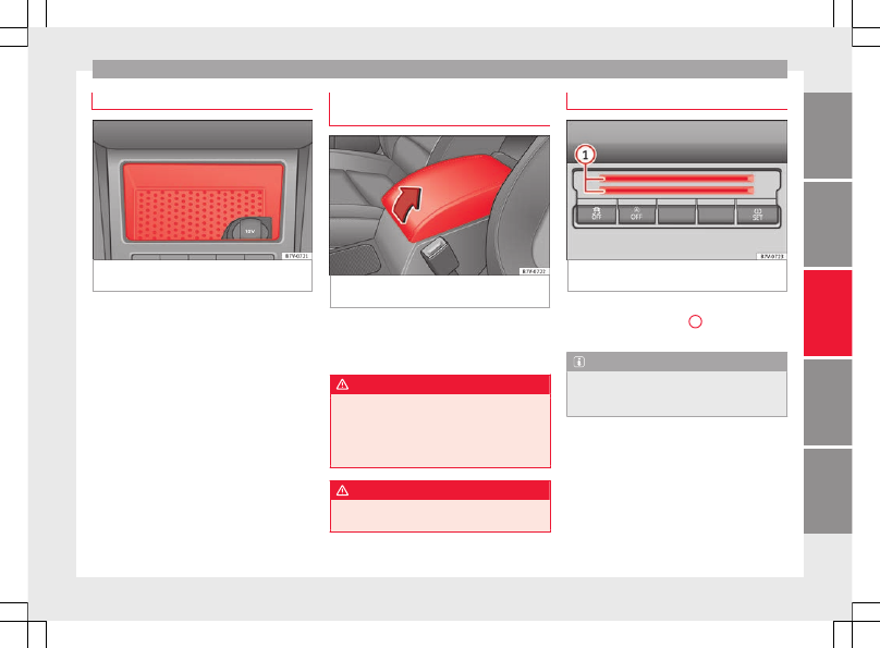
Compartment on the centre console

Fig. 178 

Compartment in the front centre con-

sole.

There is an open compartment on the centre
console 

››› 

Fig. 178

 in which there may be a

12 volt power socket 

››› 

page 170

.

Compartment in the front central arm-
rest

Fig. 179 

Storage compartment in the front

central armrest.

To open, fully lift the central armrest in the di-
rection of the arrow 

››› 

Fig. 179

.

To close, lower the central armrest.

WARNING

The centre armrest may limit the freedom of
movement of the driver's arm and cause a se-
rious accident.

Keep the centre armrest compartments

closed while the vehicle is in motion.

WARNING

The centre armrest is not designed for chil-
dren to sit on!

Card compartment*

Fig. 180 

Centre console, lower section: card

compartment

To the bottom of the centre console there is a
compartment 

››› 

Fig. 180


1

 for coins, cards,

car park tickets and similar items.

Note

To avoid theft or use by others, do not use the
compartment to store credit or ATM cards or
similar.

165

Tec

hnic

al

 d

at

a

Adv

ic

e

Oper

ation

Emer

genc

ie

s

Saf

ety

-------------------------------------------------------------------------------------------------------------------------------------------------------------

-------------------------------------------------------------------------------------------------------------------------------------------------------------

Operation

Glove compartment

Fig. 181 

Glove compartment

Fig. 182 

Glove compartment open

Opening and closing the glove compartment
Unlock the glove compartment where neces-
sary. The glove compartment is locked when
the key slot is vertical.

Pull the lever to open 

››› 

Fig. 181

.

Press the cover upwards to close.

Vehicle wallet compartment
The glove compartment is designed to store
the vehicle documentation.

The vehicle on-board documentation wallet
should always be kept in the glove compart-
ment. Insert it crosswise in the glove com-
partment.

Glove compartment cooling
There is an air vent 

››› 

Fig. 182


A

 on the rear

panel so that cooled air from the air condi-
tioner (this must be connected) is fed into
the glove compartment. Turn the air vent to
open and close it.

WARNING

The risk of serious injuries in the event of an
accident during a sudden braking manoeuvre
or turn is increased if the glove compartment
is left open.

Keep the glove compartment closed while

the vehicle is in motion.

CAUTION

For structural reasons, some model versions
will have gaps behind the glove compartment
into which small objects may fall. This could
lead to strange noises and damage to the ve-
hicle. You should therefore not keep very
small objects in the glove compartment.

Storage compartments in the rear
footwell*

Fig. 183 

Storage compartments in the foot-

well of the second row of seats.

Move the mat to one side (where applicable).

To open, pull on the rear centre part of the
cover 

››› 

Fig. 183

 (arrow).

To close, press the cover down.

WARNING

Make sure children are properly belted in and
correctly secured to avoid severe or fatal inju-
ries while the vehicle is in motion.

If you are using a child seat with a base or

foot, always install this base or foot correctly
and safely.

If the vehicle has a storage compartment in

the footwell in front of the last row of seats,

166

-------------------------------------------------------------------------------------------------------------------------------------------------------------

-------------------------------------------------------------------------------------------------------------------------------------------------------------

Transport and practical equipment

this compartment cannot be used as de-
signed; on the contrary, it must be filled us-
ing the specially designed accessory so that
the base or foot is correctly supported by the
closed compartment and the child seat is se-
cured properly. If this compartment is not
suitably secured when using a child seat with
a base or foot then the compartment cover
could rupture in an accident and the child will
be ejected and suffer serious injury.

Please read and observe the child seat

manufacturer's handling instructions.

Drawers*

Fig. 184 

Drawer under the front seat

There may be a drawer below the front seats.

Opening and closing the drawer
To open, press the button on the drawer han-
dle and pull the drawer out.

To close, push the drawer under the seat until
it clicks into place.

WARNING

If the drawer is open it could obstruct use of
the pedals. This could result in serious acci-
dent.

The drawers must remain closed while the

vehicle is in motion. Otherwise, the drawer
and any objects in it could fall into the driv-
er's footwell and obstruct the pedals.

Folding table*

Fig. 185 

Folding table on the front seat

Fold out the table by pulling on it 

››› 

Fig. 185

(arrow).

A drink holder is built into the folding table

››› 

page 168

.

To fold it back, push the folding table down
as far as possible 

››› 

Fig. 185

.

WARNING

The folding table must not be folded down
while the vehicle is in motion to avoid the
risk of injuries.

Portable waste bin*

Fig. 186 

Left sliding door trim: portable waste

bin.

The portable waste bin fits onto the bottle
holder on the trim of the left-hand sliding
door.

WARNING

Do not use the portable waste bin as an ash-
tray to avoid the risk of fire.

167

Tec

hnic

al

 d

at

a

Adv

ic

e

Oper

ation

Emer

genc

ie

s

Saf

ety

-------------------------------------------------------------------------------------------------------------------------------------------------------------

-------------------------------------------------------------------------------------------------------------------------------------------------------------

Operation

Other storage compartments

Fig. 187 

In the luggage compartment: Side

storage compartment

Fig. 188 

Other compartments in the boot

floor.

Side compartments in the luggage compart-
ment
There are other compartments 

››› 

Fig. 187


1

and 

2

 in the side of the boot. To open the

compartment 

1

, turn the catch clockwise. To

open the compartment 

2

, lift the cover.

Compartment 

1

 houses the factory fitted 

CD

changer. The compartment lid 

1

 can safely

store the tray support covers.

Compartments in the boot floor
More storage compartments can be found in
the boot floor.

Function

Necessary operations

Open the rear com-
partment 

››› 

Fig. 188

4

:

 Lift the rear of the boot floor

using the handle.

Keeping the rear com-
partment open:

 Move the hook at the rear

right of the boot and hook the
boot floor onto it 

››› 

page 152

.

Closing the compart-
ment:

 Push back the hook and

push the rear of the boot floor

4

 down.

Other storage compartments:

in the centre console, front and rear.

in the door trims, front and rear.

Coat hooks on the central door pillars and

on the rear roof handles.

Bag hook in the luggage compartment

››› 

page 152

.

WARNING

Clothing hung on the coat hooks could re-
strict the driver's view and lead to serious ac-
cidents.

Hang the clothes from the hooks so that

driver's view is not restricted.

The coat hook is suitable for light items of

clothing. Never place heavy, hard or sharp
objects in the bags.

CAUTION

Keep the CD changer compartment closed
while the vehicle is in motion to reduce vibra-
tions that could damage the changer.

Note

The first aid kit is located in the rear left com-
partment of the luggage compartment.

Drink holders

Introduction

Bottle holders
There is a bottle holder in the open compart-
ments in the driver and front passenger
doors and in that of the sliding door.

168

-------------------------------------------------------------------------------------------------------------------------------------------------------------

-------------------------------------------------------------------------------------------------------------------------------------------------------------

Transport and practical equipment

WARNING

Improper use of the drink holders can cause
injury.

Never place hot drinks in the drink holders.

During sudden braking or driving manoeu-
vres, the hot drink could be spilled and lead
to scalding.

Ensure that no bottles or other object are

dropped in the driver footwell, as they could
get under the pedals and obstruct their work-
ing.

Never place heavy containers, food or other

heavy objects in the drink holder. In the
event of an accident, these heavy objects
could be “thrown around” the vehicle interior
and cause serious injuries.

WARNING

Closed bottles inside the vehicle could ex-
plode or crack due to the heat or the cold.

Never leave a closed bottle in the vehicle if

the inside temperature is too high or too low.

CAUTION

Do not leave open cans in the drink holders
when the vehicle is in motion. They could
spill during braking, for example, and cause
damage to the vehicle and the electrical sys-
tem.

Note

The drink holders can be removed for clean-
ing.

Drink holders in front centre console

Fig. 189 

Front centre console: drink holder

To open, move the cover backwards

››› 

Fig. 189

.

To close, move the cover forwards.

Drink holders, rear*

Fig. 190 

Centre console, rear section: folding

out the drink holder

Opening and closing the drink holder in the
rear centre console

To open, move the drink holder downwards

in the direction of the arrow 

››› 

Fig. 190

.

To close, lift the drink holder.

The third row of seats has a drink holder in
the side trim compartment on the rear left.

169

Tec

hnic

al

 d

at

a

Adv

ic

e

Oper

ation

Emer

genc

ie

s

Saf

ety

-------------------------------------------------------------------------------------------------------------------------------------------------------------

-------------------------------------------------------------------------------------------------------------------------------------------------------------

Operation

Ashtray and cigarette lighter*

Ashtray

Fig. 191 

Front centre console: ashtray closed

There are ashtrays located on the front of the
centre console 

››› 

Fig. 191

 and on the rear lin-

ing of the rear door.

Opening and closing the ashtray

To open, lift the ashtray cover.

To close, push the ashtray cover down.

Emptying the ashtray

Remove the ashtray from the drink holder

or lining of the door by pulling it upwards.

After emptying the ashtray, insert it from

above into the drink holder or door lining.

WARNING

Incorrect use of the ashtray may cause a fire
or burns and other serious injuries.

Never put paper or other flammable objects

in the ashtray.

Cigarette lighter

Fig. 192 

Front centre console: lighter

Depending on the vehicle equipment, there
may be a lighter to the front of the centre
console 

››› 

Fig. 192

 or in the compartment to

the front of the centre console.

Push the button on the cigarette lighter in-

wards with the ignition on 

››› 

Fig. 192

.

Wait for the lighter to pop out slightly.

Pull out the cigarette lighter and light the

cigarette on the glowing coil 

››› 

.

Replace the cigarette lighter in its insert.

WARNING

Undue use of the cigarette lighter may cause
a fire or burns and other serious injuries.

The cigarette lighter must only be used to

light cigarettes or similar.

Never leave children unsupervised in the

vehicle. The cigarette lighter can be used
when the ignition is switched on.

Note

The cigarette lighter can also be used with
the 12 volt power socket 

››› 

page 170

.

Power sockets

Introduction

Electrical equipment can be connected to the
power sockets in the vehicle.

All connected appliances should be in per-
fect working order without any faults.

WARNING

Improper use of the power sockets or electri-
cal devices could lead to a fire and cause seri-
ous injuries.

Never leave children unsupervised in the

vehicle. The power sockets and equipment
connected to them can be used when the ig-
nition is switched on.

170

-------------------------------------------------------------------------------------------------------------------------------------------------------------

-------------------------------------------------------------------------------------------------------------------------------------------------------------

Transport and practical equipment

Should a connected electrical device over-

heat, switch it off and unplug it immediately.

CAUTION

To avoid damage to the vehicle's electrical

system, never connect equipment that gener-
ates electrical current, such as solar panels
or battery chargers, to the 12 volt power
sockets in order to charge the vehicle's bat-
tery.

Only use accessories with approved elec-

tromagnetic compatibility according to cur-
rent regulations.

To avoid damage due to voltage variations,

switch off all devices connected to the 12 V
power sockets before switching the ignition
on or off and before starting the engine.

Never connect an appliance to the 12 volt

power socket that consumes more than the
power indicated in watts. Exceeding the max-
imum power absorption could damage the ve-
hicle's electrical system.

For the sake of the environment

Do not leave the engine running when the ve-
hicle is at a standstill.

Note

Using devices with the engine stopped and

the ignition switched on will drain the bat-
tery.

Unshielded equipment can cause interfer-

ence on the radio equipment and the vehi-
cle's electrical system.

Interference can occur on the radio's AM

waveband if electrical appliances are used
near the rear window aerial.

Vehicle power sockets

Fig. 193 

Centre console, rear section: 12 volt

socket

Fig. 194 

Rear centre console: 230 Volt Euro

power socket

Depending on your vehicle version, you may
have a 12-volt power socket and/or a 230
volt power socket.

Maximum power consumption

Power sock-
et

Maximum power consumption

12 Volts

120 Watts

230 Volts

150 Watts (300 Watt peak)

The maximum capacity of each power socket
must not be exceeded. The power consump-
tion is indicated on the rating plate of each
appliance.

Where two or more appliances are connected
at the same time, the total rating of all the
connected devices must never exceed 190
Watts 

››› 

.

»

171

Tec

hnic

al

 d

at

a

Adv

ic

e

Oper

ation

Emer

genc

ie

s

Saf

ety

-------------------------------------------------------------------------------------------------------------------------------------------------------------

-------------------------------------------------------------------------------------------------------------------------------------------------------------

Operation

12 volt power socket
The 12 volt power socket will only work with
the ignition on.

Using electrical appliances with the engine
stopped and the ignition switched on will
drain the battery. Therefore, electrical devi-
ces connected to the power socket can only
be used when the engine is running.

To prevent voltage variations from causing
damage, switch off the electrical consumer
connected to the 12 volt power socket before
switching the ignition on or off and before
starting the engine.

12 volt power sockets can be found in the fol-
lowing locations in the vehicle:

Compartment in the centre of the centre

console.

Compartment in the front centre console.

Storage compartment in the front central

armrest.

Rear centre console 

››› 

Fig. 193

.

At the rear right of the luggage compart-

ment.

230 Volt Euro power socket*
The power socket only works when the en-
gine is running 

››› 

.

Connecting an electrical appliance: plug the
device into the power socket as far as possi-
ble to unlock the built-in childproof lock. The

current only flows when the childproof lock is
unlocked.

LED on the power socket 

››› 

Fig. 194

Steady green light:

The childproof lock is un-
locked. The power socket can
now be used.

Flashing red light:

There is some kind of fault
(e.g. disconnection due to ex-
cess current or temperature).

Heat protection
The 230 Volt Euro power connector converter
switches off automatically when a certain
temperature is exceeded. This disconnect
prevents overheating in the event of an in-
crease in power consumption of the connec-
ted appliance and where the atmospheric
temperature is too high. The inverter will
switch on again automatically after it has
cooled down. Appliances that are switched
on and connected to the power socket will
start up again. Therefore, switch off all elec-
trical appliances connected to the power
socket when the current converter switches
off due to overheating.

WARNING

High voltage in the electrical installation!

Liquids must not be spilt over the power

socket.

Do not plug adapters or extension cords in-

to the 230 Volt Euro power connector. Other-
wise, the built-in child safety device will
switch off and the connector will become live.

Do not plug current conductors such as a

knitting needle into the 230 Volt Euro power
connector.

CAUTION

Always follow the operating instructions for

the appliances to be connected!

Never exceed the maximum power rating as

this could damage the vehicle's general elec-
trical system.

12 volt power socket:

Only use accessories with approved elec-
tromagnetic compatibility according to
current regulations.

Never power the socket.

230 Volt Euro power socket:

Do not plug in devices or connectors that
are too heavy (e.g. a transformer) into the
power socket.

Do not connect lamps which contain a ne-
on tube.

Only plug appliances with a voltage that
matches the power socket voltage into
the power socket.

Where devices have with a high start-up
current, surge protection prevents them
from switching on. In this case, unplug

172

-------------------------------------------------------------------------------------------------------------------------------------------------------------

-------------------------------------------------------------------------------------------------------------------------------------------------------------

Air conditioning

the device and try plugging it back in af-
ter around 10 seconds.

Note

Some appliances may not work properly in

the 230 Volt Euro power connector due to a
lack of power (Watts).

The 230 Watt Euro power connector can be

modified for 115 Watt appliances and vice
versa. Consult a specialist shop for advice on
accessories to adapt the connector. SEAT rec-
ommends taking your car in for technical
service.

Air conditioning

Air conditioning

Introduction

Viewing Climatronic information
The factory-fitted radio or navigation system
screen briefly displays information relating to
Climatronic.

The units of temperature measurement is dis-
played on the factory-installed radio or navi-
gation system and, depending on the vehicle
equipment, can be set using the 

Configu-

ration

 menu on the instrument panel.

WARNING

Reduced visibility through the windows in-
creases the risk of serious accidents.

Ensure that all windows are free of ice and

snow and that they are not fogged up pre-
venting a clear view of everything outside.

The maximum heat output required to de-

frost windows quickly is only available when
the engine has reached its normal running
temperature. Only drive when you have good
visibility.

Always ensure that you use the air condi-

tioner and heated rear window to maintain
good visibility.

Never leave the air recirculation on for a

long period of time. If the cooling system is

switched off and air recirculation mode
switched on, the windows can mist over very
quickly, considerably limiting visibility.

Switch air recirculation mode off when it is

not required.

WARNING

Stuffy or used air will increase fatigue and re-
duce driver concentration possibly resulting
in a serious accident.

Never leave the fresh air fan turned off or

use the air recirculation for long periods of
time; the air in the vehicle interior will not be
refreshed.

CAUTION

Switch the air conditioner off if you think it

may be broken. This will avoid additional
damage. Have the air conditioner checked by
a specialised workshop.

Repairs to the air conditioner require spe-

cialist knowledge and special tools. SEAT rec-
ommends taking your car in for technical
service.

Do not smoke when air recirculation is

switched on in vehicles with an air condition-
er. The smoke taken in could lie on the cool-
ing system vaporiser and on the activated
charcoal cartridge of the dust and pollen fil-
ter, leading to a permanently unpleasant
smell.

»

173

Tec

hnic

al

 d

at

a

Adv

ic

e

Oper

ation

Emer

genc

ie

s

Saf

ety

-------------------------------------------------------------------------------------------------------------------------------------------------------------

-------------------------------------------------------------------------------------------------------------------------------------------------------------

Operation

Note

When the cooling system is turned off, air

coming from the outside will not be dried. To
avoid fogging up the windows, SEAT recom-
mends leaving the cooler (compressor) on. To
do this, press the 

A/C

 button. The button

lamp should light up.

If the humidity and temperature outside the

vehicle are high, condensation can drip off
the evaporator in the cooling system and
form a pool underneath the vehicle, this is
completely normal and there is no need to
suspect a leak.

Keep the air intake slots in front of the

windscreen free of snow, ice and leaves to en-
sure heating and cooling are not impaired,
and to prevent the windows from misting
over.

Controls

Read the additional information carefully

››› 

page 36

To switch a function on or off, press the ap-
propriate button. Press the button again to
switch off the function.

The LED on each control lights up to indicate
that the respective function of a control has
been switched on.

Some Climatronic controls may also be on
the air conditioner control panel located in
the rear centre console. These controls are

used to make the appropriate settings for the
rear seats.

Note

Not all Climatronic buttons are operational

in REAR mode.

The 

REAR

 button is locked in defrost mode.

Controls in the rear seats

Fig. 195 

Centre console: details of the con-

trols in the rear seats

Rotary con-

trol

››› 

Fig. 195

Description

A

Temperature selector

B

Air flow regulator

Air conditioning user instructions

The interior cooling system only works when
the engine is running and fan is switched on.

The air conditioner operates most effectively
with the windows and the electric sliding
panoramic roof closed. However, if the vehi-
cle has heated up after standing in the sun
for some time, the air inside can be cooled
more quickly by opening the windows and
the sliding electric panoramic sunroof briefly.

Setting for conditions of optimal visibility
When the air conditioning is switched on, the
temperature and the air humidity in the vehi-
cle interior drop. In this way, when the out-
side air humidity is high, the windows do not
mist over and comfort for the vehicle occu-
pants is improved.

Electronic manual air conditioning

Switch off the air recirculation 

››› 

page 176

.

Set the fan to the required setting.

Turn the temperature control to the centre

position.

Open and direct all the air outlets in the

dash panel 

››› 

page 176

.

Turn the air distribution control to the re-

quired position.

174

-------------------------------------------------------------------------------------------------------------------------------------------------------------

-------------------------------------------------------------------------------------------------------------------------------------------------------------

Air conditioning

With Climatronic

Press the 

AUTO

 button.

Set the temperature to +22°C (+72°F).

Open and direct all the air outlets in the

dash panel 

››› 

page 176

.

Climatronic: Switching the measuring units
for temperature on the radio display or the
navigation system installed with the default
settings
Switching the temperature indication from
Celsius to Fahrenheit on the radio display or
the navigation system is carried out in the
menu on the instrument panel

››› 

page 30

.

The cooling system does not switch on
If the air conditioning system cannot be
switched on, this may be caused by the fol-
lowing:

The engine is not running.

The fan is switched off.

The air conditioning fuse is blown.

The outside temperature is lower than ap-

proximately +3°C (+38°F).

The air conditioner compressor has been

temporarily switched off because the engine
coolant temperature is too high.

Another fault in the vehicle. Have the air

conditioner checked by a specialised work-
shop.

Special features
If the humidity and temperature outside the
vehicle are high, 

condensation can drip off

the vaporiser in the cooling system and form
a pool underneath the vehicle. This is normal
and does not indicate a leak!

Note

After starting the engine, any residual humid-
ity in the air conditioner could mist over the
windscreen. Switch on the defrost function as
soon as possible to clear the windscreen of
condensation.

175

Tec

hnic

al

 d

at

a

Adv

ic

e

Oper

ation

Emer

genc

ie

s

Saf

ety

-------------------------------------------------------------------------------------------------------------------------------------------------------------

-------------------------------------------------------------------------------------------------------------------------------------------------------------

Operation

Air vents

Fig. 196 

Air vents in the dash panel

Air vents
Never close the air vents 

››› 

Fig. 196


A

 com-

pletely to ensure heating, cooling and venti-
lation inside the vehicle.

Turn the thumbwheel in the required direc-

tion to open and close the air vents. When
the thumbwheel is in the  position, the cor-
responding air vent is closed.

Change the air direction using the ventila-

tion grille lever.

There are other air vents that cannot be ad-
justed on the dash panel 

B

, in the footwell

and in the rear area of the interior.

CAUTION

Never place food, medicines or other heat-
sensitive objects close to the air vents. Being
heat-sensitive, they may be damaged or
made unsuitable for use by the air coming
from the air vents.

Note

The air from the vents flows through the vehi-
cle interior and out through the outlets below
the rear window. The slots must not be cov-
ered with items of clothing or other objects.

Air recirculation

Air recirculation mode prevents the ambient
air from entering the interior.

When the outside temperature is very high,
selecting manual air recirculation mode for a
short period refreshes the vehicle interior
more quickly.

For safety reasons, air recirculation mode is
switched off when the  button is press-
ed or the air distributor turned to  

››› 

.

Switching the recirculation mode on and off
manually on the air conditioning (Electronic
manual air conditioning) 

Switching on: press the button  until the
lamp on the button lights up.

176

-------------------------------------------------------------------------------------------------------------------------------------------------------------

-------------------------------------------------------------------------------------------------------------------------------------------------------------

Air conditioning

Switching off: press the button  until the
lamp on the button switches off.

Switching the recirculation mode on and off
manually on the Climatronic 

Switching on: press the button  until the
lamp on the button lights up.

Switching off: press the button  until the
lamp on the button switches off.

Automatic air recirculation mode 
Fresh air enters the vehicle interior in posi-
tion . If the system detects a high con-
centration of hazardous substances in the
ambient air, air recirculation mode is switch-
ed on automatically. When the level of impur-
ities drops to within a normal range, recircu-
lation mode is switched off.

The system is unable to detect unpleasant
smells.

With the following outside temperatures and
conditions the air recirculation 

does not

switch on automatically:

The cooling system is switched on (the 

AC

button is lit up) and the outside temperature
is below +3°C (+38°F).

The cooling system and the windscreen

wipers are switched off and the outside tem-
perature is below +10°C (+50°F).

The cooling system is switched off and the

outside temperature is below +15°C (+59°F).
The windscreen wiper is switched on.

Switching the automatic air recirculation
mode on and off
Switching on: press the button  until the
right lamp on the button lights up.

Switching off: press the button  until all
the lamps on the button are switched off.

Switching the automatic air recirculation
mode off temporarily

Press the  button once to temporarily

switch to manual air recirculation mode in
the event of unpleasant smells from outside.
The left indicator lamp turns on.

After more than two seconds, press the 

button again to restart automatic air recircu-
lation. The right indicator lamp turns on.

WARNING

Observe the safety warnings 

››› 

 in Intro-

duction on page 173

.

If the cooling system is switched off and air

recirculation mode switched on, the windows
can mist over very quickly, considerably limit-
ing visibility.

Switch air recirculation mode off when it is

not required.

CAUTION

Do not smoke when air recirculation is
switched on in vehicles with an air condition-
er. The smoke taken in could lie on the cool-
ing system vaporiser and on the activated
charcoal cartridge of the dust and pollen fil-
ter, leading to a permanently unpleasant
smell.

Note

Climatronic: air recirculation mode switches
on to prevent exhaust gas from entering the
vehicle interior when it is in reverse and
while the automatic windscreen wipers are
working.

Auxiliary heater* (additional
heater)

Introduction

The auxiliary heater is powered by fuel from
the vehicle's fuel tank and can be used while
the vehicle is in motion and at a standstill.
Select the mode required (

heat

 or 

fan

)

››› 

page 179

 on the dash panel.

In winter, the auxiliary heater can be used in

heat

 mode before switching on the ignition

to remove any ice, mist or snow from the
windscreen (thin layers only).

»

177

Tec

hnic

al

 d

at

a

Adv

ic

e

Oper

ation

Emer

genc

ie

s

Saf

ety

-------------------------------------------------------------------------------------------------------------------------------------------------------------

-------------------------------------------------------------------------------------------------------------------------------------------------------------

Operation

WARNING

The auxiliary heater fumes contain carbon di-
oxide, an odourless and colourless toxic gas.
Carbon monoxide can cause people to lose
consciousness. It can also cause death.

Never switch on the auxiliary heater or

leave it running in places that are enclosed or
unventilated.

Never program the independent heating

system to be activated and operated in
closed, unventilated areas.

WARNING

The components of the auxiliary heater ex-
haust system heat up a great deal. This could
cause a fire.

Always park your vehicle so that no part of

the exhaust system can come in contact with
flammable materials (such as dried grass).

CAUTION

Never place food, medicines or other heat-
sensitive objects close to the air vents. Food,
medicines and other heat-sensitive objects
may be damaged or made unsuitable for use
by the air coming from the air vents.

Switching the auxiliary heater on and
off

Switching the auxiliary heater on:

Manually using the instant on/off
button.

››› 

page 

174

ON

Manually using the remote control.

››› 

page 

178


Automatically at the programmed
and enabled on time.

››› 

page 

179

Switching the auxiliary heater off:

Manually using the instant on/off
button for the air conditioner.

››› 

page 

174

OFF

Manually using the remote control.

››› 

page 

178


Automatically after the programmed
time.

››› 

page 

179


Automatically when the light comes
on  (fuel reserve).

››› 

page 

261


Automatically when the battery pow-
er drops to a very low level.

››› 

page 

280

Special feature
After switching the auxiliary heater off, it con-
tinues to run for a short period to completely
burn any fuel remaining in the auxiliary heat-

er. The exhaust gases are also extracted from
the system.

Remote control

Fig. 197 

Auxiliary heater: remote control

Fig. 197

Meaning

ON

Switch the auxiliary heater on.

OFF

Switch the auxiliary heater off:

A

Aerial.

B

Light.

The auxiliary heater may accidentally switch
on if a button is pressed on the remote con-
trol by mistake. This may also occur outside
the range of the remote control or if the light
flashes.

178

-------------------------------------------------------------------------------------------------------------------------------------------------------------

-------------------------------------------------------------------------------------------------------------------------------------------------------------

Air conditioning

Remote control light
The remote control light provides users with
different information at the push of a button:

Battery light

Fig. 197


B

Meaning

Lights up green for
around two seconds.

The auxiliary heater has been
switched on using the 

ON

 but-

ton.

Lights up red for
around two seconds.

The auxiliary heater has been
switched off using the 

OFF

 but-

ton.

Slowly flashes green
for around two sec-
onds.

No on

a)

 signal has been re-

ceived.

Quickly flashes green
for around two sec-
onds.

The auxiliary heater is locked.
Possible causes: the fuel tank
is almost empty, the battery
charge is very low or there is a
fault.

Flashes red for
around two seconds.

No off

a)

 signal has been re-

ceived.

Lights up orange for
around two seconds,
then green or red.

The remote control battery is
almost flat. However, the on or
off signal has been received,
respectively.

Lights up orange for
around two seconds,
then flashes green or
red.

The remote control battery is
almost flat. The on or off signal
has not been received, respec-
tively.

Battery light

Fig. 197


B

Meaning

Flashes orange for
around five seconds.

The remote control battery is
flat. The on or off signal has
not been received, respective-
ly.

a)

Within its range, the remote control might not receive the sig-

nal sent by the vehicle receiver. In this case, the remote control
will send an error message whether the auxiliary heater is on or
off. Come closer to the vehicle and press the corresponding but-
ton on the remote control once again.

Replacing the remote control battery
If the light 

››› 

Fig. 197


B

 on the remote con-

trol does not come on when the button is
pressed, the remote control battery should
soon be replaced.

The battery is located beneath a cover on the
back of the remote control. Turn the slot to
the left using a flat, blunt object (e.g. a coin).
When changing the battery, use another bat-
tery of the same model and observe the po-
larity when fitting it 

››› 

.

Range
The receiver is in the interior of the vehicle.
The remote control, when fitted with new bat-
teries, has a range of several hundred me-
tres. Obstacles between the remote control
and the vehicle, bad weather conditions and
discharged batteries can considerably reduce
the range of the remote control.

An optimum range is obtained by keeping
the remote control vertical, with the aerial

››› 

Fig. 197


A

 pointing upwards. When doing

so, do not cover the aerial with your fingers
or with the palm of your hand.

There must be a minimum distance of 2 me-
tres between the remote control and the vehi-
cle.

CAUTION

The radio frequency remote control con-

tains electronic components. Therefore, avoid
getting it wet and being knocked and protect
it from direct sunlight.

Use of inappropriate batteries may damage

the remote control. For this reason, always re-
place the used battery with another of the
same voltage, size and specifications.

For the sake of the environment

Please dispose of old batteries so that they

do not harm the environment.

The remote control battery may contain

perchlorate. Observe the legal requirements
for their disposal.

Programming the auxiliary heater

The heater or ventilation inside the vehicle
can be programmed for a certain period.

»

179

Tec

hnic

al

 d

at

a

Adv

ic

e

Oper

ation

Emer

genc

ie

s

Saf

ety

-------------------------------------------------------------------------------------------------------------------------------------------------------------

-------------------------------------------------------------------------------------------------------------------------------------------------------------

Operation

Before programming, check that the day is
correctly set in the 

Auxiliary heater -

day of the week

 menu 

››› 

.

Enabling the 

Auxiliary heater

 menu on

the instrument panel

From the main menu, select the 

Auxili-

ary heater

 submenu and press the 

OK

button on the windscreen wiper lever.

OR: press the 

 or 

 arrow buttons on the

multifunction steering wheel until the 

Aux-

iliary heater

 menu is displayed.

Menu op-
tions

Description

Switching
on
Switching
off

The auxiliary heater can be set to come
on automatically if required. To do so,
select a timer:
– The timer is displayed marked with a

.

– 

Only one timer can be selected. If a

timer has been selected, 

Prog. ON

will be displayed on the screen. If no
timer has been selected, the dash
panel display will show 

Prog. OFF

.

– To modify the programmed timer, se-
lect another timer or select the 

Off

option.

Timer 1
Timer 2
Timer 3

Three different timers (hh.mm) can lat-
er be selected using the 

On

 option. If

the auxiliary heater is to be switched
on for just a certain day of the week,
select the day of the week and the
time for the auxiliary heater to come
on.

Menu op-
tions

Description

Duration

The operating time may vary between
10 and 60 minutes and can be set to
5-minute intervals.

Operating
mode

Set to heat or ventilate the vehicle in-
terior when the auxiliary heater is
switched on.

Day

Set the current day of the week.

Factory
settings

The predefined factory values for the
functions of this menu are restored.

Back

This returns to the main menu.

Checking programming
If the 

timer

 has been switched on after

switching the ignition off, the light on button

 will remain lit for around 10 seconds.

WARNING

Never program the independent heating sys-
tem to be activated and operated in closed,
unventilated areas. The auxiliary heater
fumes contain carbon dioxide, an odourless
and colourless toxic gas. Carbon monoxide
can cause people to lose consciousness. It
can also cause death.

Operating instructions

The auxiliary heater exhaust system located
below the vehicle must be kept clear of snow,
mud and other objects. The exhaust gases
must not be obstructed in any way. The ex-
haust gases generated by the auxiliary heater
are removed via an exhaust pipe fitted under-
neath the vehicle.

On heating the vehicle interior, depending on
the outside temperature the warm air is first
directed at the windscreen and then to the
rest of the vehicle interior through the air
vents. If the air vents are turned towards the
windows, for example, the form of air distri-
bution may be affected.

Depending on the outside temperature, the
temperature at which the auxiliary heater
warms the vehicle interior may be somewhat
higher if the heating or air conditioner tem-
perature control is set to maximum before
switching the heating on.

Depending on the engine, vehicles with aux-
iliary heater may be fitted with a second bat-
tery in the luggage compartment that is re-
sponsible for powering the auxiliary heater.

When will the auxiliary heater will not switch
on?

The auxiliary heater requires about as

much power as the dipped beam headlights.

180

-------------------------------------------------------------------------------------------------------------------------------------------------------------


Content      ..     9      10      11      12     ..