Haima S5. Instruction - part 3
Engine block 1A-29
1.10.2 Valve Mechanism Dismantling/
Mounting
1. Dismantle cylinder head(see the cylinder head
dismantling).
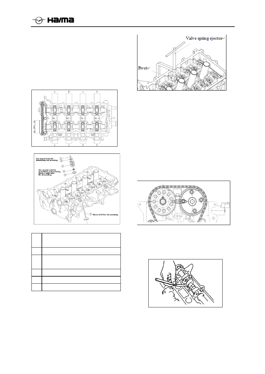
2. Dismantle parts according to sequence
illustrated in the figure. .
3. Mount the parts according to the sequence
reverse to the dismantling process.
1
Valve Half (see dismantling/mounting
explanations)
2
Valve spring upper seat
3
Valve spring (see the mounting
explanations)
4
Valve spring lower seat
5
Valve (see the mounting explanations)
6 Valve
oil
seal
Explanations on dismantling of valve
keeper
Use special tool valve spring pressure, remove the
valve keeper.
Explanations on inspection of valve
clearance
1. Dismantle the cylinder head hood (see
cylinder head hood dismantling part).
2. Confirm if the engine has been cooled.
3. Measure valve clearance.
(1) Rotate the crankshaft along the clockwise
direction, making the piston located at the
stopping place on No.1 Cylinder, namely, gas
distribution mark shall be adjusted to the
position indicated in the right figure.
(2) Use plug gauge to measure valve clearances
of all cylinders at Mark A indicated in the
figure.
★
Note:If the valve clearance exceeds the
standard value, replace the tappet(see the
valve clearance’s adjustment)valve
clearance’s standard value (when engine is in
cooling state):