Haima 7. Electrical System of Body. Instruction - part 3
Wiper and washer
T-23
Diagnostic program
Steps
Check
Display
Measures
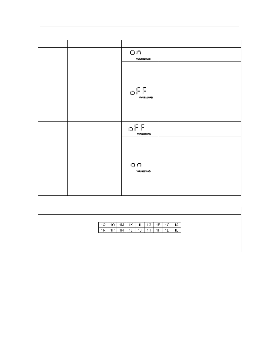
1
Current climate control
unit display OFF. Open
rear windshield switch.
Go to the next step..
Measure the voltage of combination
instrument terminal 3R
Is the voltage equal to 5V?
l If this value is satisfied, replace the
combination instrument;
l If this value is unsatisfied, check the
following parts.
— Climate control unit
— Harness
(combination
instrument- climate control unit)
2
Current climate control
unit display ON. Open rear
windshield switch.
The
signal
input
of
combination
instrument is normal.
Measure the voltage of combination
instrument terminal 3R.
Is the voltage equal to 3V?
l If this value is satisfied, replace the
combination instrument;
l If this value is unsatisfied, Check the
following parts.
— Climate control unit
— Harness(combination instrument-
climate control unit)
DTC 08
TNS replay signal On/Off
Combination instrument connectors
Harness side connector
(Viewed from the harness side)
XMET18W016