Lancia DELTA. Instruction - part 13


  Index      Instructions     Lancia DELTA. Instruction


Search            copyright infringement  


Content      ..     11      12      13      14     ..


Lancia DELTA. Instruction - part 13


200

IN AN EMERGENCY

INFLATION PROCEDURE

Put on the protective gloves provided 
with the quick tyre repair kit.

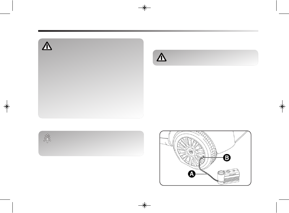
❍ Engage the handbrake. Unscrew the tyre valve cap,

take out the filler hose A - fig. 4 and tighten the ring
nut B on the tyre valve;

fig. 4

L0E0077m

The bottle contains ethylene glycol. It con-
tains latex that might cause allergic reac-
tions. It is harmful if swallowed. It is irri-

tant for the eyes. It may cause sensitisation if in-
haled or on contact. Avoid contact with eyes, skin
and clothes. In the event of contact, wash immedi-
ately with plenty of water. Do not induce vomiting
if swallowed. Rinse your mouth and drink plenty of
water. Call a doctor immediately. Keep out of the
reach of children. The product must not be used by
asthmatics. Do not breathe in the vapours during
insertion and suction. Call a doctor immediately if
allergic reactions are noted. Store the bottle in the
specific compartment, away from sources of heat.
The sealant has an expiry date.

Replace the bottle containing out-of-date
sealant. Dispose of the bottle and the sealant
properly. Dispose of the components in com-

pliance with national and local regulations.

195-232 Delta GB 1ed  03/03/14  09.14  Pagina 200

-------------------------------------------------------------------------------------------------------------------------------------------------------------

IN AN EMERGENCY

201

4

❍ make sure that switch C - fig. 5 for the compressor is

in position 0 (off), start the engine, insert pin E - fig.
5a into the power socket and switch on the compres-
sor by placing switch C - fig. 5 in position I (on); 

❍ inflate the tyre to the pressure specified in the “Infla-

tion pressure” paragraph, in chapter “6”. For a more
accurate reading, check pressure value on pressure
gauge D - fig. 5 with the compressor off; 

❍ if after 5 minutes you cannot reach at least 1.5 bar, un-

plug the compressor from the valve and the power
socket, then move the car forward about 10 metres in
order to distribute the sealant inside the tyre evenly,
then repeat the inflation operation;

fig. 5

L0E0078m

fig. 5a

L0E0288m

❍ if after this operation it is still not possible to reach at

least 1.8 bar after 5 minutes, do not start driving since
the tyre is excessively damaged and the quick tyre re-
pair kit cannot guarantee suitable sealing. Contact a
Lancia Dealership;

❍ if the tyre reaches the pressure specified in the “Infla-

tion pressure” paragraph in chapter “6”, start driving
immediately;

Apply the adhesive label in a position clear-
ly visible by the driver as a reminder that the
tyre has been treated with the quick repair

kit. Drive carefully, particularly on bends. Do not
exceed 80 km/h. Do not accelerate or brake sud-
denly.

195-232 Delta GB 1ed  03/03/14  09.14  Pagina 201

-------------------------------------------------------------------------------------------------------------------------------------------------------------

202

IN AN EMERGENCY

❍ after driving for about 10 minutes stop and check the

tyre pressure again; pull up the handbrake

If the pressure falls below 1.8 bar, do not dri-
ve any further: the Fix & Go automatic quick
tyre repair kit cannot guarantee suitable

sealing because the tyre is too damaged. Contact a
Lancia Dealership.

❍ if you get a pressure reading of at least 1.8 bar, re-

store the correct pressure (with engine running and
handbrake on) and resume driving;

❍ drive with the utmost care to the nearest Lancia Deal-

ership.

Inform the Dealership that the tyre has been
repaired using the quick tyre repair kit. Give
the booklet to the personnel charged with

handling the treated tyre.

CHECKING AND RESTORING TYRE PRESSURE

The compressor can also be used solely for restoring pres-
sure. Release the quick coupling and connect directly to
the tyre valve fig. 6; in this way, the bottle will not be con-
nected to the compressor and no sealant will be injected. 

fig. 6

L0E0287m

195-232 Delta GB 1ed  03/03/14  09.14  Pagina 202

-------------------------------------------------------------------------------------------------------------------------------------------------------------

IN AN EMERGENCY

203

4

BOTTLE REPLACEMENT PROCEDURE

To replace the bottle, proceed as follows:
❍ disconnect connection A - fig. 7;
❍ turn the bottle to be replaced anticlockwise and raise

it;

❍ fit the new bottle and turn it clockwise;
❍ connect connection A to the bottle and fit the trans-

parent tube B in the dedicated space.

fig. 7

L0E0289m

REPLACING A WHEEL

GENERAL INSTRUCTIONS

The car may be originally fitted with a space-saver wheel
(for versions/markets, where provided).
Wheel replacement and correct use of the jack and space-
saver wheel call for some precautions as listed below.

The space-saver wheel provided (for ver-
sions/markets, where provided) is specific for
the car; do not use it on other models, or use

the space-saver wheel of other models on your car.
The space-saver wheel must only be used in the
event of emergency. Never use it for more than strict-
ly necessary and never exceed 80 km/h. On the
space-saver wheel there is an orange label, sum-
marising the main warnings regarding space-saver
wheel usage restrictions.

195-232 Delta GB 1ed  03/03/14  09.14  Pagina 203

-------------------------------------------------------------------------------------------------------------------------------------------------------------

Never remove or cover the label. Never apply
a hub cap on a space-saver wheel. The la-
bel bears the following instructions in four

languages: WARNING! FOR TEMPORARY USE
ONLY! 80 KM/H MAX.! REPLACE WITH STAN-
DARD WHEEL AS SOON AS POSSIBLE. DO NOT
COVER THIS LABEL. 
If you change the type of wheel (alloy rims instead
of steel rims) you will have to change the entire set
of fastening bolts with another set of suitably sized
bolts.

Alert other drivers that the car is stationary
in compliance with local regulations: hazard
warning lights, warning triangle, etc. Any

passengers on board should leave the car, especial-
ly if it is heavily laden. Passengers should stay
away from on-coming traffic while the wheel is be-
ing changed. If parked on a slope or rough surface,
chock the wheels with wedges or other suitable de-
vices.

204

IN AN EMERGENCY

The jack can only be used for changing
wheels on the car with which it is provided
or on cars of the same model. Never use the

jack for other purposes, such as lifting other car
models. Never use it for repair operations under the
car. Incorrect positioning of the jack may cause the
car to fall. Do not use the jack for loads higher than
those shown on the label. Snow chains cannot be fit-
ted to the space-saver wheel. Therefore, if a front
(drive) wheel is punctured and chains are required,
a rear wheel should be fitted at the front of the car
and the space-saver wheel should be fitted to the
rear. This way, with two normal front driving
wheels, you can install the snow chains on them,
thus resolving the emergency.

If the hub cap is not installed properly, it may
detach when the vehicle is running. Never
tamper with the inflation valve. Never intro-

duce tools of any kind between rim and tyre. Reg-
ularly check tyre and space-saver wheel pressure,
complying with the data in the chapter “6”.

195-232 Delta GB 1ed  03/03/14  09.14  Pagina 204

-------------------------------------------------------------------------------------------------------------------------------------------------------------

IN AN EMERGENCY

205

4

The driving characteristics of the car may
change when a space-saver wheel is fitted.
Avoid violent acceleration and braking,

abrupt steering and fast cornering. The total life
of a space-saver wheel is approximately 3,000 km,
after which it must be replaced by another wheel
of the same type. Never install a standard tyre on
a rim designed for use as a space-saver wheel. Have
the wheel repaired and refitted as soon as possi-
ble. Using two or more space-saver wheels at the
same time is forbidden. Do not apply grease to the
bolt threads before assembly: they might sponta-
neously unscrew.

Tool box (versions with HI-FI Bose)

There is a tool box located in the luggage compartment
for versions with HI-FI Bose.
This box contains: 
❍ screwdriver;
❍ tow hook;
❍ wheel bolt spanner;
❍ wheel bolt access spanner;
❍ alloy rims centring device;
❍ jack. 

REMOVING THE SUBWOOFER 
(versions with HI-FI Bose)
(for versions/markets, where provided)

IMPORTANT The following procedure only applies to cars
equipped with HI-FI Bose systems with subwoofer (for
versions/markets, where provided).

SUBWOOFER AND SPACE-SAVER WHEEL

Proceed as follows to remove the subwoofer:
❍ open the luggage compartment, pull tab A - fig. 10 and

lift up the mat;

❍ undo locking device A - fig. 8 and lift up the subwoofer.

Then remove connection cable B from velcro attach-
ment C;

fig. 8

L0E0176m

195-232 Delta GB 1ed  03/03/14  09.14  Pagina 205

-------------------------------------------------------------------------------------------------------------------------------------------------------------

206

IN AN EMERGENCY

❍ rest the subwoofer to one side in the luggage com-

partment, remove the container and take out the space-
saver wheel;

❍ change the wheel as described in this chapter.
At the end of the operation:
❍ reposition the container and place the subwoofer on

top of it, taking care to position it according to the in-
structions on the container (fig. 9) so that the arrow
on the spacer is pointing in the direction of travel.

❍ rest cable B - fig. 8 on velcro attachment C to avoid

pinching it. Then tighten locking device A - fig. 8. Low-
er the luggage compartment mat.

fig. 9

L0E0177m

TAKING OUT THE SPACE-SAVER WHEEL

Please note that:
❍ the jack weight is 1.76 kg;
❍ the jack requires no adjustment;
❍ the jack cannot be repaired; if it breaks, it must be

replaced with a new one of the same type;

❍ no tool other than its cranking device may be fitted on

the jack.

To change a wheel, proceed as follows:
❍ stop the car where it is not a danger to other road users

and you can replace the wheel safely. The ground
should be flat if possible, and sufficiently firm;

❍ turn the engine off and engage the handbrake;
❍ engage first gear or reverse;
❍ lift up the luggage compartment mat using handle 

A - fig. 10 (in the presence of a double load compart-
ment, first lift the upper cover and then the luggage
compartment mat).

❍ unscrew the locking device B - fig. 10;
❍ take out the tool box C and place it next to the wheel

to be changed;

❍ take out the space-saver wheel D - fig. 10;
❍ use the provided screwdriver to remove the hub cap,

levering the dedicated opening on the outer edge;

195-232 Delta GB 1ed  03/03/14  09.14  Pagina 206

-------------------------------------------------------------------------------------------------------------------------------------------------------------

IN AN EMERGENCY

207

4

fig. 10

L0E0081m

❍ in the presence of a double load compartment, lift the

double compartment mat and attach it to the luggage
compartment mat as shown in fig. 10.

❍ for cars fitted with alloy rims, remove the press-fitted

hub cap using the screwdriver provided;

❍ loosen the fixing bolts for the wheel to be changed by

about one turn using the spanner provided E - fig. 11;

❍ turn the cranking device to partially open it;
❍ position the jack near the wheel to be replaced at the

reference point O on the side member;

❍ make sure that the splines F - fig. 12 on the jack are

firmly fitted to tab G on the side member;

fig. 11

L0E0082m

195-232 Delta GB 1ed  03/03/14  09.14  Pagina 207

-------------------------------------------------------------------------------------------------------------------------------------------------------------

fig. 12

L0E0083m

208

IN AN EMERGENCY

❍ warn anybody nearby that the car is about to be lift-

ed. They must stay clear and not touch the car until
it is back on the ground;

❍ fit the handle H - fig. 12 into device I of the jack and

lift the car until the wheel is several centimetres off the
ground. When turning the jack handle make sure that
it can turn freely without scraping your hand against
the ground. The moving components of the jack
(screws and joints) can also cause injuries: avoid touch-
ing them. If you become soiled with the lubricating
grease, clean it off thoroughly;

❍ make sure the contact surfaces on the space-saver

wheel are clean so that the retaining bolts will not come
loose;

❍ fit the space-saver wheel, aligning pins T - fig. 13 with

one of the holes A on the wheel;

❍ tighten the 4 fixing bolts;
❍ turn the jack handle to lower the car and remove the

jack;

❍ fully tighten the bolts, passing alternately from one bolt

to the opposite one, following the order illustrated in
fig. 13.

195-232 Delta GB 1ed  03/03/14  09.14  Pagina 208

-------------------------------------------------------------------------------------------------------------------------------------------------------------

IN AN EMERGENCY

209

4

fig. 13

L0E0113m

REFITTING THE STANDARD WHEEL

Following the procedure described previously, raise the
car and remove the space-saver wheel.

Versions with steel rims

Proceed as follows:
❍ make sure the contact surfaces between standard wheel

and hub are clean so that the fastening bolts will not
come loose;

❍ fit the standard wheel inserting the 4 bolts into the

holes;

❍ using the spanner provided, tighten the fixing bolts;
❍ press-fit the hub cap, aligning the special splining (on

the cap) with the inflation valve;

❍ lower the car and remove the jack;
❍ using the spanner provided, fully tighten the bolts in

the sequence shown previously.

195-232 Delta GB 1ed  03/03/14  09.15  Pagina 209

-------------------------------------------------------------------------------------------------------------------------------------------------------------

210

IN AN EMERGENCY

Versions with alloy rims 
❍ Place the wheel onto the hub and tighten the bolts us-

ing the spanner provided;

❍ lower the car and remove the jack;
❍ using the spanner provided, fully tighten the bolts in

the sequence shown in fig. 8;

❍ refit the press-fitted hub cap, making sure that the ref-

erence hole on the wheel is aligned with the reference
pin on the cap.

IMPORTANT If it is not fitted properly, the hub cap may
detach when the vehicle is running.

At the end of the operation
❍ Stow the space-saver wheel D - fig. 10 in the space pro-

vided in the luggage compartment;

❍ fit the partially open jack in its box forcing it lightly to

prevent it from vibrating when travelling;

❍ put the tools back into place in the box;

❍ stow the container, complete with tools, in the space-

saver wheel and tighten the locking device B - fig. 10;

❍ reposition the luggage compartment mat correctly.

IMPORTANT Do not use air chambers tubes with tube-
less tyres. Check the inflation pressure of the tyres and the
space-saver wheel periodically.

Various fixing bolts and space-saver wheels,
specific and differing in structural charac-
teristics, are used depending on the wheel rim

type (alloy or steel). Fixing bolts for alloy rims can
be identified by the presence of a permanent wash-
er and a hollow side on the bolt head.
Therefore, you will need to contact a Lancia Deal-
ership to get the correct type of fixing bolts and
space-saver wheel if you change the type of wheels
fitted (alloy rims instead of steel rims, or vice ver-
sa). Keep the bolts fitted as standard in case of re-
use of the wheels originally mounted on the car.

195-232 Delta GB 1ed  03/03/14  09.15  Pagina 210

-------------------------------------------------------------------------------------------------------------------------------------------------------------

IN AN EMERGENCY

211

4

REPLACING A BULB

GENERAL INSTRUCTIONS

❍ Before changing a bulb, check the contacts for oxida-

tion;

❍ burnt-out bulbs must be replaced by others of the same

type and power;

❍ always check the direction of the beam after chang-

ing a headlight bulb, for safety reasons;

❍ when a light is not working, check that the corre-

sponding fuse is intact before changing the bulb. For
the location of fuses, refer to the “Replacing fuses”
paragraph in this chapter.

IMPORTANT The headlight inner surface might be slight-
ly misted: this does not indicate a fault, it is a natural phe-
nomenon due to low temperature and the air humidity lev-
el. Misting will disappear rapidly when the headlights are
turned on. The presence of drops inside the headlights in-
dicates infiltration of water. Contact a Lancia Dealership.

Modifications or repairs to the electric sys-
tem that are not carried out properly or do
not take the system technical specifications

into account can cause malfunctions leading to the
risk of fire. 

Halogen bulbs contain gas under pressure, if
they break glass fragments may be thrown
around.

When handling halogen bulbs just touch the
metal part. If the transparent bulb is touched
with the fingers, its lighting intensity is re-

duced and life of the bulb may be compromised. In
the event of accidental contact, wipe the bulb with
a cloth moistened with alcohol and leave it to dry.

Where possible, it is advisable to have bulbs
changed at a Lancia Dealership. Proper op-
eration and direction of the external lights

are essential for driving in safety and comply with
law.

195-232 Delta GB 1ed  03/03/14  09.15  Pagina 211

-------------------------------------------------------------------------------------------------------------------------------------------------------------

212

IN AN EMERGENCY

IMPORTANT When the weather is cold or damp or after
heavy rain or after washing, the surface of headlights or
rear lights may steam up and/or form drops of conden-
sation on the inside. This is a natural phenomenon due
to the difference in temperature and humidity between the
inside and the outside of the glass which does not indicate
a fault and does not compromise the normal operation of
lighting devices. The mist disappears quickly when the
lights are turned on, starting from the centre of the dif-
fuser, extending progressively towards the edges.

TYPES OF BULBS fig. 14

Various types of bulbs are fitted to your car:
A. Glass bulbs: they are press-fitted. Pull to remove them.
B. Bayonet type bulbs: to remove this type of bulb from

its holder press the bulb, turn it anticlockwise and re-
move it.

C. Tubular bulbs: to remove, release them from their con-

tacts.

D-E. Halogen bulbs: to remove the bulb, release the clip

holding the bulb in place.

fig. 14

L0E0084m

195-232 Delta GB 1ed  03/03/14  09.15  Pagina 212

-------------------------------------------------------------------------------------------------------------------------------------------------------------

IN AN EMERGENCY

213

4

LED

LED

D1S(*) / H7

H1(*) / H7

PY 24W

LED

WY5W

LED

LED

W5W

H11

W16W

W16W

5L/5K

12V 5W

12V 5W

W5W

D

D

B

A

 –

C

E

B

B

C

C

A

 –

55 W

55 W

24 W

5 W

5 W

55 W

16 W

16 W

5 W

5 W

5 W

Bulbs

Type

Power

Figure ref.

Front side lights/Daytime running lights

Rear side lights

Dipped beam headlights

Main beam headlights

Front direction indicator

Rear direction indicator

Side direction indicator

Brake light

Third brake light

Number plate light

Fog lights

Rear fog light

Reverse light

Front roof light (white LEDs)

Rear roof light

Glove compartment/luggage 
compartment light

Puddle light 

(*) Xenon gas discharge bulb 

195-232 Delta GB 1ed  03/03/14  09.15  Pagina 213

-------------------------------------------------------------------------------------------------------------------------------------------------------------

214

IN AN EMERGENCY

REPLACING AN EXTERIOR BULB

FRONT LIGHT CLUSTERS fig. 15

These contain the bulbs for the dipped beam headlights,
main beam headlights and direction indicators. The bulbs
are arranged as follows:
A. Main beam headlights:
B. Dipped beam headlights;
C. Direction indicators.

DIPPED BEAM HEADLIGHTS

With incandescent bulbs

To change the bulb, proceed as follows:
❍ remove the protective cover B - fig. 15;
❍ release the bulb holder clip A - fig. 16;
❍ disconnect the electrical connector B;
❍ remove the bulb C and replace it;
❍ fit the new bulb, ensuring that the outline of the met-

al part coincides with the splining on the curve of the
headlight. Then reconnect the electrical connector B
and reattach the bulb holder clip A;

❍ refit the protective cover B - fig. 15.

fig. 15

L0E0154m

fig. 16

L0E0155m

195-232 Delta GB 1ed  03/03/14  09.15  Pagina 214

-------------------------------------------------------------------------------------------------------------------------------------------------------------

IN AN EMERGENCY

215

4

With gas discharge bulbs (Xenon) 
(for versions/markets, where provided)

MAIN BEAM HEADLIGHTS

With incandescent bulbs

To change the bulb, proceed as follows:
❍ remove the protective cover A - fig. 15;
❍ release the bulb holder clip A - fig. 17;
❍ disconnect the electrical connector B;
❍ remove the bulb C and replace it;
❍ fit the new bulb, ensuring that the outline of the met-

al part coincides with the splining on the curve of the
headlight. Then reconnect the electrical connector B
and reattach the bulb holder clip A;

❍ refit the protective cover A - fig. 15.

fig. 17

L0E0156m

Due to the high power supply voltage, gas
discharge bulbs (Xenon) should only be re-
placed by specialised personnel: danger of

death! Contact a Lancia Dealership.

With gas discharge bulbs (Xenon) 
(for versions/markets, where provided)

Due to the high power supply voltage, gas
discharge bulbs (Xenon) should only be re-
placed by specialised personnel: danger of

death! Contact a Lancia Dealership.

195-232 Delta GB 1ed  03/03/14  09.15  Pagina 215

-------------------------------------------------------------------------------------------------------------------------------------------------------------


Content      ..     11      12      13      14     ..