Saturn Astra (2008 year). Instruction - part 14


  Index      Saturn     Saturn Astra (2008 year) - instruction in english


Search            copyright infringement  


Content      ..     12      13      14      15     ..


Saturn Astra (2008 year). Instruction - part 14


Headlamp Aiming

The optical headlamp aiming system
has been preset at the factory
and should need no further
adjustment.

However, If the vehicle is damaged
in a crash, the headlamp aim
may be affected and adjustment
may be necessary.

If oncoming vehicles flash their high
beams at you, this may also mean
the vertical aim needs to be adjusted.

It is recommended that the vehicle
is taken to your dealer/retailer for
service if the headlamps need to be
re-aimed. It is possible however, to
re-aim the headlamps as described.

The vehicle should:

Be placed so the headlamps
are 25 ft. (7.6 m) from a light
colored wall.

Have all four tires on a perfectly
level surface which is level all
the way to the wall.

Be placed so it is perpendicular
to the wall.

Not have any snow, ice, or
mud on it.

Be fully assembled and all other
work stopped while headlamp
aiming is being done.

Have a full tank of fuel and
one person or 160 lbs (75 kg)
on the driver seat.

Have all tires properly inflated.

Headlamp aiming is done with the
vehicle’s low-beam headlamps.
The high-beam headlamps will be
correctly aimed if the low-beam
headlamps are aimed properly.

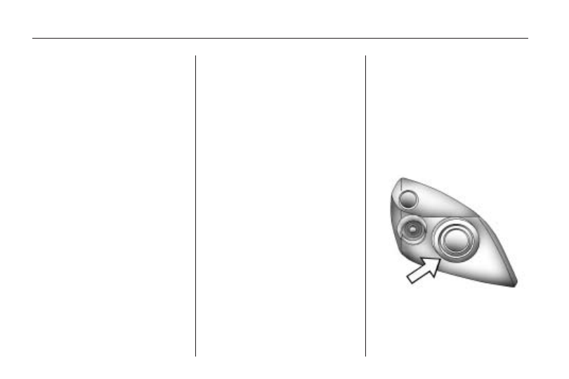
To adjust the vertical aim on
the headlamps:

1. Open the hood. See Hood

Release on page 9-5 for more
information.

2. Locate the aim dot on the lens of

the low-beam headlamp.

9-26

Vehicle Service and Care

-------------------------------------------------------------------------------------------------------------------------------------------------------------

3. Record the distance from the

ground to the aim dot on the
low-beam headlamp.

4. At a wall, measure from the

ground upward (A) to the
recorded distance from Step 3
and mark it.

5. Draw or tape a horizontal line (B)

on the wall the width of the
vehicle at the height of the
mark in Step 4.

Notice: Do not cover a headlamp
to improve beam cut-off when
aiming. Covering a headlamp may
cause excessive heat build-up
which may cause damage to the
headlamp.

6. Turn on the low-beam headlamps

and place a piece of cardboard
or equivalent in front of the
headlamp not being adjusted.
Do not place it directly on
the headlamp. This allows only
the beam of light from the
headlamp being adjusted to
be seen on the flat surface.

7. Locate the vertical headlamp

aiming screws, which are under
the hood near each headlamp
assembly.

The adjustment screw can be
turned with a 6 mm socket
wrench.

8. Turn the vertical aiming screw

until the headlamp beam is aimed
to the horizontal tape line. Turn it
clockwise or counterclockwise
to raise or lower the angle of
the beam.

Vehicle Service and Care

9-27

-------------------------------------------------------------------------------------------------------------------------------------------------------------

9. Make sure that the light from the

headlamp is positioned at the
bottom edge of the horizontal
tape line. The lamp on the left (A)
shows the correct headlamp aim.
The lamp on the right (B) shows
the incorrect headlamp aim.

10. Repeat Steps 7 through 9 for

the opposite headlamp.

Bulb Replacement

For the proper type of replacement
bulbs, see Replacement Bulbs
on page 9-33.

For any bulb changing procedure
not listed in this section, contact
your dealer/retailer.

Halogen Bulbs

{

CAUTION

Halogen bulbs have
pressurized gas inside and can
burst if you drop or scratch the
bulb. You or others could be
injured. Be sure to read and
follow the instructions on the
bulb package.

Front Turn Signal Lamps

1. The bulbs of the turn signal lamp

are replaced through openings in
the front wheel wells. Turn the
wheel to gain access to the push
tabs and remove the cover.

9-28

Vehicle Service and Care

-------------------------------------------------------------------------------------------------------------------------------------------------------------

2. Turn the bulb socket

counterclockwise and pull
straight out.

3. Turn bulb counterclockwise

and remove.

4. Install new bulb.

5. Reverse Steps 2 through 4 to

reinstall.

Taillamps
(Five-Door Hatchback)

A. Backup Lamp

B. Taillamp

C. Taillamp/Stoplamp/Turn

Signal Lamp

To replace one of these bulbs:

1. Open the liftgate.

2. To replace the bulbs on the

driver side, turn both locks
and remove the cover.

To replace the bulbs on the
passenger side, turn the lock
clockwise and remove the cover.

3. Detach the plug connector

from the bulb assembly.

Vehicle Service and Care

9-29

-------------------------------------------------------------------------------------------------------------------------------------------------------------

4. Turn the nuts counterclockwise

and hold the outside of taillamp
assembly.

5. Pull the taillamp assembly

straight out.

6. Remove the three nuts.

7. Press on the tabs on the outside

of bulb assembly and remove the
bulb assembly.

8. Remove the bulb from the bulb

assembly.

9. Install a new bulb without

touching the glass.

10. Reinstall the bulb assembly in

taillamp assembly.

11. Make sure the seals are applied

to the taillamp assembly and
screws.

12. Insert the taillamp assembly

into the body.

13. Reinstall the three nuts.

14. Attach the plug connector to the

bulb assembly.

Taillamps
(Three-Door Hatchback)

A. Backup Lamp

B. Taillamp

C. Taillamp/Stoplamp/Turn

Signal Lamp

9-30

Vehicle Service and Care

-------------------------------------------------------------------------------------------------------------------------------------------------------------

To replace one of these bulbs:

1. Open the liftgate. See Liftgate on

page 2-6 for more information.

2. Detach the plug connector from

the bulb assembly.

3. Turn the nuts counterclockwise

and hold the outside of taillamp
assembly.

4. Pull the taillamp assembly

straight out.

5. Remove the seal.

6. Press on the tabs on outside of

bulb assembly and remove the
bulb assembly.

7. Remove the bulb from the bulb

assembly.

8. Install a new bulb without

touching the glass.

9. Reinstall the bulb assembly in

taillamp assembly.

10. Make sure the seals are applied

to the taillamp assembly and
screws.

11. Insert the taillamp assembly

into the body.

12. Reinstall the three nuts.

13. Attach the plug connector to the

bulb assembly.

Vehicle Service and Care

9-31

-------------------------------------------------------------------------------------------------------------------------------------------------------------

License Plate Lamp

To replace one of these bulbs:

1. Push tab in and pull down on it to

remove the license plate lamp.

2. Turn and pull the license plate

lamp toward you through the
opening.

3. Turn the bulb socket

counterclockwise and pull the
bulb straight out of the socket.

4. Install the new bulb.

5. Reverse Steps 1 through 3 to

reinstall the license plate lamp.

9-32

Vehicle Service and Care

-------------------------------------------------------------------------------------------------------------------------------------------------------------

Replacement Bulbs

Exterior Lamp

Bulb

Number

Front Turn
Signal Lamp

3157 NAK

License Plate
Lamp

W5W

Parking Lamp

4157K

Taillamp

W21

For replacement bulbs not listed
here, contact your dealer/retailer.

Electrical System

Add-On Electrical
Equipment

Notice: Do not add anything
electrical to your vehicle unless
you check with your dealer/retailer
first. Some electrical equipment
can damage your vehicle and the
damage would not be covered by
your warranty. Some add-on
electrical equipment can keep
other components from working
as they should.

Add-on equipment can drain your
vehicle’s battery, even if your vehicle
is not operating.

Your vehicle has an airbag system.
Before attempting to add anything
electrical to your vehicle, see
Servicing Your Airbag-Equipped
Vehicle 
on page 1-34.

Headlamp Wiring

The headlamp wiring is protected
by fuses in the fuse block.
An electrical overload will cause
the lamps to turn off. If this happens,
have your headlamp wiring checked
right away.

Vehicle Service and Care

9-33

-------------------------------------------------------------------------------------------------------------------------------------------------------------

Windshield Wiper Fuses

The windshield wiper motor is
protected by a circuit breaker and a
fuse. If the motor overheats due
to heavy snow, etc., the wiper
will stop until the motor cools.
If the overload is caused by some
electrical problem, have it fixed.

Power Windows and
Other Power Options

Circuit breakers in the fuse block
protect the power windows and
other power accessories. When the
current load is too heavy, the
circuit breaker opens and closes,
protecting the circuit until the
problem is fixed or goes away.

Fuses

The wiring circuits in your vehicle
are protected from short circuits by a
combination of fuses and circuit
breakers. This greatly reduces the
chance of damage caused by
electrical problems.

Look at the silver-colored band
inside the fuse. If the band is broken
or melted, replace the fuse. Be sure
to replace a bad fuse with a new one
of the identical size and rating.

There are two fuse blocks in
your vehicle: one in the engine
compartment and one in the trunk.

There is a fuse puller located
on the rear compartment fuse block.
See Rear Compartment Fuse
Block 
on page 9-36. It can be used
to easily remove fuses from the
fuse block.

Engine Compartment
Fuse Block

The engine compartment fuse block
is located in the front left side of
the engine compartment. Engine
Compartment Overview 
on
page 9-6
.

To open the fuse block cover,
insert a tool into the latch and turn.
Pull up on the cover to remove.

Notice: Spilling liquid on any
electrical components on
your vehicle may damage it.
Always keep the covers on any
electrical component.

9-34

Vehicle Service and Care

-------------------------------------------------------------------------------------------------------------------------------------------------------------

Fuses

Usage

1

Antilock Brake
System (ABS) Valves

2

ABS Pump

Fuses

Usage

4

Climate Control
System (Ignition)

5

Engine Cooling
Fan (AT and AC only)

Fuses

Usage

6

Engine Cooling Fan

7

Windshield & Liftgate
Glass Washer Motor

Vehicle Service and Care

9-35

-------------------------------------------------------------------------------------------------------------------------------------------------------------

Fuses

Usage

8

Horn

10

Door Locks

13

Foglamps

14

Windshield Wipers
(high speed)

15

Windshield Wipers
(low speed)

16

Antilock Brake System,
Brake Lamp Switch

17

Vacuum Pump

18

Starter

20

Air Conditioning Clutch

21

Engine Control
Module (ECM)
(Main Relay)

22

ECM (Battery)

24

Fuel Pump/Injectors

Fuses

Usage

26

ECM (Sensor and
Actuators)

27

Power Steering

28

Automatic
Transmission (Battery)

29

Automatic
Transmission (Ignition)

30

ECM (Ignition)

32

Brake Switch

34

Steering Column
Module

35

Radio

36

OnStar™ Module/
OnStar™ Interface
Module/Display

Rear Compartment Fuse
Block

To open the liftgate, See Liftgate on
page 2-6
.

The rear compartment fuse block is
located on the left side of the
cargo area behind a cover.

9-36

Vehicle Service and Care

-------------------------------------------------------------------------------------------------------------------------------------------------------------

Use the fuse puller, to remove and replace fuses.

Fuses

Usage

1

Front Power Window

3

Cluster

Fuses

Usage

4

Climate Control
System (Battery)

11

Rear Defogger

Fuses

Usage

12

Rear Windshield Wiper

14

Climate Control
System (Ignition)

Vehicle Service and Care

9-37

-------------------------------------------------------------------------------------------------------------------------------------------------------------

Fuses

Usage

16

Front Passenger Seat
Detection Sensor

17

Tire Pressure
Monitoring
System (TPMS)/
Rain Sensor/Inside
Rearview Mirror

18

Interior Lights

21

Outside Mirror Heating

22

Sunroof

23

Rear Power Window

24

Diagnostic Link
Connector

29

Accessory Power
Outlet (APO)

34

Sunroof

38

Door Locks

39

Seat Heating Driver

40

Seat Heating Front
Passenger

Tires

Your new vehicle comes with
high-quality tires made by
a leading tire manufacturer.
If you ever have questions about
the tire warranty and where to
obtain service, see the “Limited
Warranty, Maintenance and
Owner Assistance Information”
instruction for details.

{

CAUTION

Poorly maintained and
improperly used tires are
dangerous.

Overloading your tires can
cause overheating as a
result of too much flexing.
You could have an air-out
and a serious accident.
See Loading the Vehicle
on page 8-30.

(Continued)

CAUTION

(Continued)

Underinflated tires pose
the same danger as
overloaded tires.
The resulting accident
could cause serious
injury. Check all tires
frequently to maintain the
recommended pressure.
Tire pressure should be
checked when your tires
are cold. See Inflation - Tire
Pressure 
on page 9-46.

Overinflated tires are more
likely to be cut, punctured,
or broken by a sudden
impact — such as when
you hit a pothole. Keep
tires at the recommended
pressure.

(Continued)

9-38

Vehicle Service and Care

-------------------------------------------------------------------------------------------------------------------------------------------------------------

CAUTION

(Continued)

Worn, old tires can cause
accidents. If your tread
is badly worn, or if your
tires have been damaged,
replace them.

See High-Speed Operation
on page 9-47 for inflation
pressure adjustment for
high speed driving.

Low-Profile Tires

If the vehicle has 225/40ZR18
or 215/45R18 size tires, they
are classified as low-profile
performance tires. These tires
are designed for very responsive
driving on wet or dry pavement.
You may also notice more
road noise with low-profile
performance tires and that they
tend to wear faster.

Notice:

If the vehicle has

low-profile tires, they are
more susceptible to damage
from road hazards or curb
impact than standard profile
tires. Tire and/or wheel
assembly damage can occur
when coming into contact with
road hazards like, potholes,
or sharp edged objects,
or when sliding into a curb.
The vehicle warranty does not
cover this type of damage.
Keep tires set to the correct
inflation pressure and,
when possible avoid contact
with curbs, potholes, and
other road hazards.

Winter Tires

If the vehicle has 225/40ZR18 or
215/45R18 size tires, they are
classified as low-profile performance
tires. These tires are designed for
very responsive driving on wet or dry
pavement. If you expect to drive
on snow or ice covered roads often,
you may want to get winter tires
for your vehicle. All season tires
provide good overall performance on
most surfaces but they may not
offer the traction you would like or
the same level of performance
as winter tires on snow or ice
covered roads.

Winter tires, in general, are
designed for increased traction on
snow and ice covered roads.
With winter tires, there may be
decreased dry road traction,
increased road noise, and shorter
tire tread life. After switching to
winter tires, be alert for changes in
vehicle handling and braking.

Vehicle Service and Care

9-39

-------------------------------------------------------------------------------------------------------------------------------------------------------------

See your dealer/retailer for details
regarding winter tire availability
and proper tire selection. Also, see
Buying New Tires on page 9-54.

If you choose to use winter tires:

Use tires of the same brand and
tread type on all four wheel
positions.

Use only radial ply tires of the
same size, load range, and
speed rating as your original
equipment tires.

Winter tires with the same speed
rating as the original equipment tires
may not be available for H, V, W,
Y and ZR speed rated tires.
If you choose winter tires with a
lower speed rating, never exceed
the tire’s maximum speed capability.

Tire Sidewall Labeling

Useful information about a
tire is molded into its sidewall.
The examples below show
a typical passenger vehicle
tire and a compact spare
tire sidewall.

(A) Tire Size

:

The tire size is

a combination of letters and
numbers used to define a
particular tire’s width, height,
aspect ratio, construction
type, and service description.
See the “Tire Size” illustration
later in this section for more
detail.

(B) TPC Spec (Tire
Performance Criteria
Specification)

:

Original

equipment tires designed to
GM’s specific tire performance
criteria have a TPC specification
code molded onto the sidewall.
GM’s TPC specifications meet
or exceed all federal safety
guidelines.

(C) DOT (Department of
Transportation)

:

The

Department of Transportation
(DOT) code indicates that the tire
is in compliance with the U.S.
Department of Transportation
Motor Vehicle Safety Standards.

Passenger (P-Metric) Tire

Example

9-40

Vehicle Service and Care

-------------------------------------------------------------------------------------------------------------------------------------------------------------

(D) Tire Identification Number
(TIN)

:

The letters and numbers

following DOT (Department
of Transportation) code is the
Tire Identification Number (TIN).
The TIN shows the manufacturer
and plant code, tire size, and
date the tire was manufactured.
The TIN is molded onto both
sides of the tire, although only
one side may have the date
of manufacture.

(E) Tire Ply Material

:

The type

of cord and number of plies in the
sidewall and under the tread.

(F) Uniform Tire Quality
Grading (UTQG)

:

Tire

manufacturers are required to
grade tires based on three
performance factors: treadwear,
traction, and temperature
resistance. For more information
see Uniform Tire Quality
Grading 
on page 9-56.

(G) Maximum Cold Inflation
Load Limit

:

Maximum load

that can be carried and the
maximum pressure needed to
support that load.

(A) Tire Ply Material

:

The type

of cord and number of plies in the
sidewall and under the tread.

(B) Temporary Use Only

:

The compact spare tire or
temporary use tire has a tread
life of approximately 3,000 miles
(5 000 km) and should not be
driven at speeds over 50 mph
(80 km/h). The compact
spare tire is for emergency use
when a regular road tire has
lost air and gone flat. If your
vehicle has a compact spare tire.
See Compact Spare Tire on
page 9-67 
and If a Tire
Goes Flat 
on page 9-60.

(C) Tire Identification
Number (TIN)

:

The letters and

numbers following the DOT
(Department of Transportation)
code is the Tire Identification
Number (TIN). The TIN shows
the manufacturer and plant code,
tire size, and date the tire was
manufactured. The TIN is
molded onto both sides of the
tire, although only one side may
have the date of manufacture.

Compact Spare Tire Example

Vehicle Service and Care

9-41

-------------------------------------------------------------------------------------------------------------------------------------------------------------


Content      ..     12      13      14      15     ..