Pontiac Montana SV6 (2006 year). Instruction - part 22
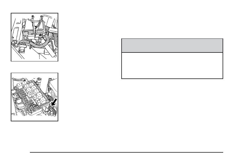
If your vehicle has the
3.5L V6 engine, the
terminal is located under a
tethered cap at the front
of the underhood fuse
block. Squeeze the tabs
and swing the cap out
of the way to access the
remote positive (+)
terminal.
If your vehicle has the
3.9L V6 engine, the
terminal is located under
the fuse block cover.
Remove the cover
to access the remote
positive (+) terminal.
See Engine Compartment Overview on page 5-12
for more information on the location of the
remote positive (+) terminals. You should always
use the remote positive (+) terminal instead of
the positive (+) terminal on your battery.
{
CAUTION:
An electric fan can start up even when the
engine is not running and can injure you.
Keep hands, clothing and tools away from any
underhood electric fan.
3.5L V6 Engine
3.9L V6 Engine
5-42