Westfalia. Testing repair electrical manual - part 64


  Index      Westfalia     Westfalia (903.662) testing repair electrical manual in english


Search            copyright infringement  


Content   ..  62  63  64  65   ..


Westfalia. Testing repair electrical manual - part 64


AR86.60-D-0051-
01B

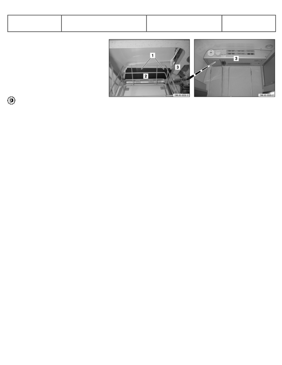
Remove/ install cover panel from
hanging cabinet


1 Open stowage compartment on
lateral hanging cabinet (3). 

2 Unscrew bolts (1). 

3 Remove cover panel (2). 

4 Install in the reverse order. 

 When tightening bolts (1)

ensure that no electrical lines are
pinched below the cover panel to
prevent damaging the leads and
avoiding malfunctions of the
components.


D86.60-0033-04

AR68.30-D-4630-
01A

Remove/ install kitchen element
front paneling


1 Move bench seat (1) toward
front. 

 See Operating Instructions 

2 Remove upholstery (2). 

3 Remove caps from bolts (4) 

4 Unscrew bolts (4) 

5 Remove paneling (3) 

6 Install in the reverse order.


D68.30-1121-02 

D68.30-1122-02

AS00.00-Z-0025-
01A

Risk of injury caused by body
parts becoming jammed, pinched
or severed by doors, covers,
flaps or by loose components

Keep body parts well clear
when moving doors, covers,
flaps and components. Wear
protective gloves and
protective shoes.

 Danger!

Potential risks 

Risk of injury 
Body parts can be pinched or severed when working on doors, covers,
flaps or loose components.


D00.00-1113-01

Safety precautions/instructions 
- Secure doors, covers and flaps in such a way that
they do not close unintentionally. 
- Support or secure loose components in their
positions with suitable means so that they do not
fall. 
- Wear protective gloves and protective shoes. 
- Have another person help when removing or
installing heavy components or when working on
hard to reach components.


First aid measures: 
Move the victim out of the risk area. 
Treat the wound to stop the bleeding. If any
arteries have been cut, the flow of blood to that
area must be stopped (by applying a tourniquet
above the injured area). 

 Consult a physician immediately in the case of

serious injuries (heavy bleeding, severed limbs,
etc.), swelling, broken bones, or if victim is
unconscious.

AR54.21-D-0030-
01A

Remove/install cover of roof air
conditioning switched-mode
power supply


 Tape assembly area

(marking) with friction tape in
order to avoid damage when
removing and installing the cover
of the switched-mode power
supply (1). 

1 Unscrew bolts (2). 

2 Remove cover of switched-
mode power supply (1). 

3 Install in the reverse order.


D54.21-1107-06

AR54.21-D-0021-
01A

Carry out switch position of 1 or
2 batteries


1 Switches 
5 Central electronics


D54.21-1124-10

1 Press DOWN button (23) 1   

 Within 60 seconds after the

central electronics (5) is in self-
test mode 

2 Check of symbol (7) and the
multiple display (8). 

 The symbol for battery

operation (7) and 1b in the
multiple display (8) means that
switch (1) is adjusted to 1
additional battery in the vehicle. 

 The symbol for battery

operation (7) and 2b in the
multiple display (8) means that
switch (1) is adjusted to 2
additional batteries in the vehicle.


D54.21-1125-04

AR54.21-D-0021-
02A

Carry out switch position for
battery model 1 or 2


2 Switches 
5 Central electronics


D54.21-1124-10

1 Press the down button (23) 2   

 Within 60 seconds after the

central electronics (5) is in self-
test mode 

2 Check of symbol (7) and the
multiple display (8). 

 Symbol for battery operation

(7) and 1A in the multiple display
(8) means that switch (2) is
adjusted to additional battery
model 1 (sunshine) in the vehicle. 

 Symbol for battery operation

(7) and 2A in the multiple display
(8) means that switch (2) is
adjusted to additional battery
model 2 (DELTA) in the vehicle.


D54.21-1125-04

AR54.21-D-0021-
03A

Carry out switch position for
refrigerator box or refrigerator


3 Switches 
5 Central electronics


D54.21-1124-10

1 Press the down button (23) 3   

 Within 60 seconds after the

central electronics (5) is in self-
test mode 

2 Check of symbol (15) and the
multiple display (8). 

 Symbol for refrigerator box,

refrigerator (15) und CB in the
multiple display (8) means that
switch (3) is adjusted to the
refrigerator box in the vehicle. 

 Symbol for refrigerator box,

refrigerator (15) und CS in the
multiple display (8) means that
switch (3) is adjusted to the
refrigerator in the vehicle.


D54.21-1125-04

AR54.21-D-0021-
04A

Carry out switch position
degrees Celsius or degrees
Fahrenheit


4 Switches 
5 Central electronics


D54.21-1124-10

1 Press the down button (23) 4   

 Within 60 seconds after the

central electronics (5) is in self-
test mode 

2 Check of multiple display (8). 

 If °C is displayed in the

multiple display (8), this means
that switch (4) is adjusted to
degrees Celsius. 

 If °F is displayed in the

multiple display (8), this means
that switch (4) is adjusted to
degrees Fahrenheit.


D54.21-1125-04


Content   ..  62  63  64  65   ..