Lotus Evora. Instruction - part 62


  Index      Lotus     Lotus Evora - service repair instruction 2009 year


Search            


Content   ..  60  61  62  63   ..


Lotus Evora. Instruction - part 62


Lotus Service Notes   


    Section MR

MR.6 - COMPONENT LOCATION & FUSE RATINGS
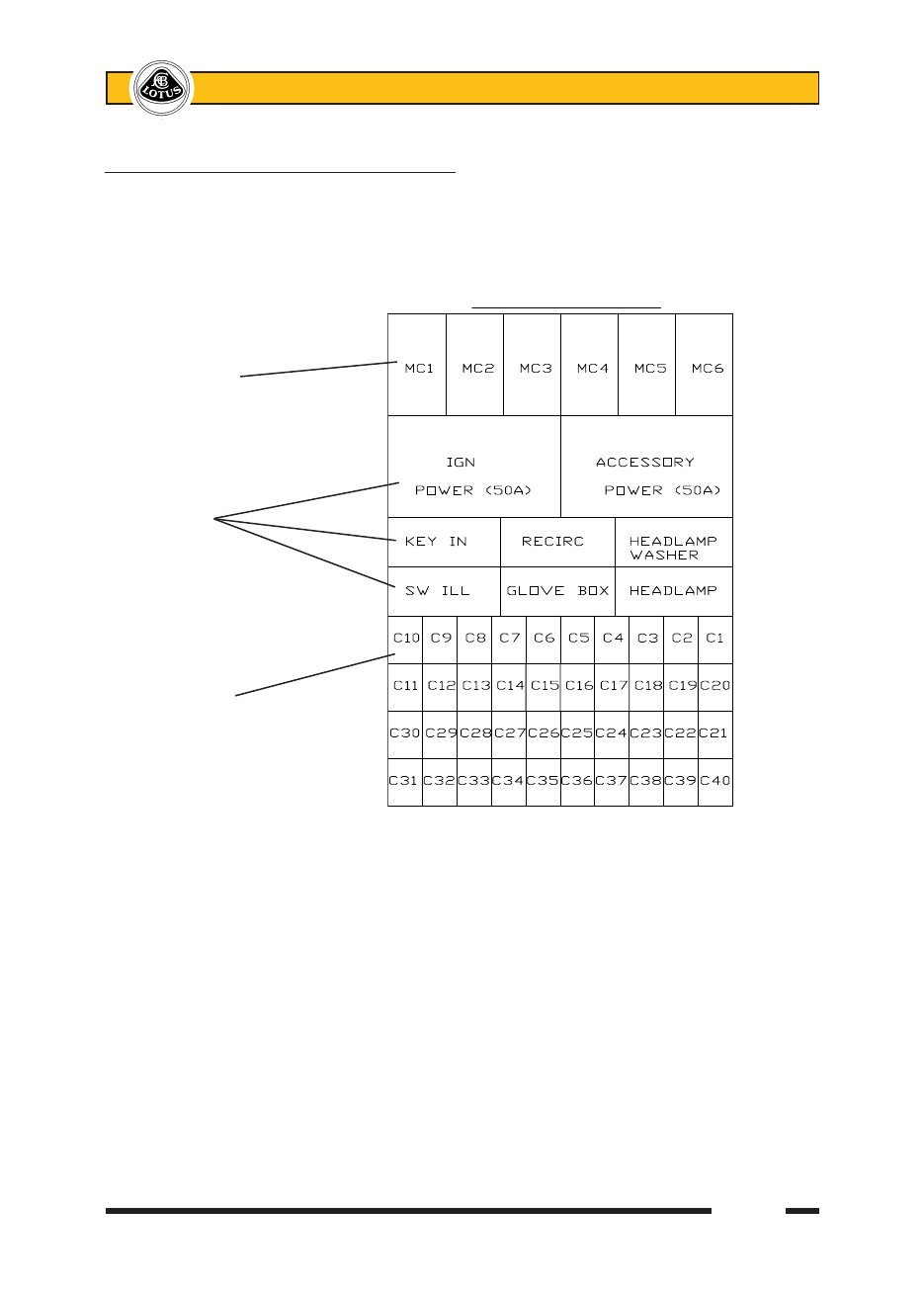
Main Fusebox

The main fuse and relay boxes are located at the front of the passenger footwell, protected by a removable 

panel secured by a quarter turn fastener at each top corner, and a location channel on the floor.  Forty slots 

are provided for mini fuses which are numbered, and coloured according to their amperage rating, and may be 

pulled out from their slots using the fuse extractor tool clipped to the fusebox.   Six maxi fuses protecting major 

circuits are also provided, along with six single contact change over micro relays and two 50A power relays. 


Slot  Rate Circuit

C1  10A    Horn

C2  5A    Battery services

C3  5A    Alarm B+

C4  20A    Rad fan relay 1

C5  20A    Rad fan relay 3

C6  10A    Radio B+

C7  5A    Key-in relay

C8  2A    Ignition switch

C9  15A    Driver’s window

C10  15A    Pass. window

C11  7.5A   Hazard & Turn

C12  3A    Interior lighting

C13  20A    Int. control mod.

C14  -   

C15  5A    LH sidelamps

C16  5A    RH sidelamps

C17  15A    LH headlamp

C18  15A    RH headlamp

C19  15A    Main beam

C20  3A    Rear foglamp

Slot  Rate Circuit

C21  3A    Ign. services

C22  5A    ABS

C23  3A    Homelink

C24  3A    Brake lamps

C25  15A    HL powerwash

C26  5A    Alarm ignition

C27  -

C28  5A    HVAC ignition

C29  5A    Washer jets

C30 5A    SRS unit

C31  3A    Heated mirrors

C32  5A    Washer pump

C33 5A    Mirror/window sw.

C34 20A    Wiper motor

C35 -

C36 20A    Interior fan

C37  10A    Cabin pwr. socket

C38 -

C39 -

C40 -

Slot  Rate Circuit

MC1 40A  Battery positive

MC2 40A  B+, ignition

MC3 40A  Accessories

MC4 40A  ABS B+

MC5 25A  ABS B+

MC6 25A  HRS

Maxi fuses

Relays

Mini fuses


Lotus Service Notes   


    Section MR

Front Relay Blocks

Mounted on the front fusebox panel, is a block of relays, the layout of which is inverted for opposite drive 

hands:


RHD                                  LHD

Integrated Control Module

Also mounted on the front fusebox panel is the integrated control module (ICM) which is used to perform 

switching and control functions for many of the circuits.  The module uses 4 harness connector blocks designated 

A,B,C,D, with all connection details identified on the relevant circuit diagram, and summarised below:


        13             1    8        1    6       1   11           1


A              B         C           D

          26           14   16       9    12     7   22         12           

m268


Lotus Service Notes   


    Section MR

Key to ICM Diagram

Pin  Description

A1   Supply for indicator relays

A2   Left indicators output

A3   -

A4   -

A5   Fog switch input

A6   -

A7   -

A8   Headlamp powerwash output

A9   A.c. recirc. control output

A10  Supply for recirc. & powerwash control

A11  Horn output

A12  Supply for horn & foglamps

A13  Supply for indicator current sense

A14  Right indicators output

A15  Battery ground

A16  -

A17  -

A18  -

A19  LED lighting option input

A20  Left indicator switch input

A21  Right indicator switch input

A22  Intermittent variable input

A23  DRL option input

A24  Battery ground

A25  Fog lights output

A26  Indicators supply after current sensing

B1   Main beam flash input

B2   Recirc. switch input

B3   Hazard switch input

B4   Wiper int. input

B5   Washer monitor input

B6   HRW switch input

B7   A.c. request switch input

B8   Driver door switch input

B9   CDL switch illumination

B10  CDL switch monitor

B11  Lock status input

B12  Unlock status input

B13  -

B14  Passenger door switch input

B15  Headlamp switch input

B16  Sidelamps switch input

Pin  Description

C1   Main beam flash power input

C2   Int. fan fast input

C3   Fog switch illum. input

C4   -

C5   Drive away locking output

C6   Sidelights switch illum. output

C7   HRS output

C8   Recirc. switch illum. output

C9   A.c. request output

C10  -

C11  -

C12  Diagnostic comms. KW2000

D1   ICM main supply & main lighting

D2   -

D3   HRS switch illumination

D4   Ignition switch input

D5   Headlamp relay output

D6   Hazard switch illumination

D7   Hazard active illumination

D8   A.c. switch illumination

D9   Headlamps switch illum. output

D10  -

D11  Door open output

D12  Sidelights output

D13  Main beam solenoid output

D14  Int. fan speed input

D15  Horn switch output

D16  -

D17  Eng. man. rpm input

D18  Wiper park input

D19  Wiper relay control output

D20  Auto demist input

D21  Indicators fault monitor input

D22  -


Lotus Service Notes   


    Section MR

Rear Fusebox

Fuses and relays for the engine bay and rear mounted systems are contained in a fusebox mounted in the 

cabin, behind the left hand rear quarter trim panel.  For access, use a coin to release the quarter turn fastener 

on the lower edge of the removable panel, and unhook the top edge.  Twenty slots are provided for mini fuses 

which are numbered, and coloured according to their amperage rating, and may be pulled out from their slots 

using the fuse extractor tool clipped to the fusebox.   Two maxi fuses protecting major circuits are also provided, 

along with four single contact change over micro relays, and two power relays. 


Fuse colours

2A - Black    5A - Orange     15A - Light blue

3A - Violet    7.5A - Brown    20A - Yellow

4A - Pink     10A - Red      25A - Clear

Slot  Rate Circuit

R1  10A    ECU, fan relay 3

R2  7.5A   Injectors

R3  10A    Ignition coils

R4  2A    Re-circ. pump

R5  -

R6  -   

R7  5A    ECU ignition

R8  7.5A   Engine solenoids

R9  5A    O2 heaters

R10  5A    Alternator ign.

Slot  Rate Circuit

R11  7.5A   A.c. compressor

R12  3A    Rev lamp, camera

R13  -

R14  -

R15  3A    Boot lamps

R16  10A    Boot pwr. socket

R17  20A    Amplifier

R18  5A    Fuel filler flap

R19  10A    Fuel pump

R20  5A   Alternator B+

Slot  Rate  Circuit

MR1  30A  Crank & main rly.

MR2  30A  Busbar R17-R20

    Relays

    Mini fuses

    Maxi fuses


ohe25


Content   ..  60  61  62  63   ..