Lotus Evora. Instruction - part 9
Lotus Service Notes
Section BV
To remove/refit rear bumper
1. From inside the boot, remove the trim panel from around the latch mechanism, and disconnect the har-
nesses to the rear fog and reverse lamps, parking sensors and reverse camera.
2. From within each rear wheelarch, release the single fixing securing the lower edge of the bumper to the
subframe bracket, and the two fixings at each side securing the diffuser finisher to the diffuser. Also release
the single fixing securing the top edge of the bumper to the clamshell flange.
3. From within each side of the boot, remove the two grommets, and release the two fixings securing the
bumper top edge to the clamshell. Also remove the single screw just outboard of the tail lamp.
4. Remove the 5 fixings along the rear edge of the boot aperture, clamping the bumper to the clamshell.
5. Carefully withdraw the bumper from the clamshell.
6. Refit the bumper in reverse order to removal, adjusting the panel heights and gaps as necessary.
BV.8 - DOOR MIRRORS
The two door mirrors are electrically adjustable, and, only when the engine is running, are heated on de-
mand in conjunction with the HRS for a maximum period of 10 minutes. An optional specification includes an
electric fold facility for use when parking or negotiating narrow gaps.
Each mirror comprises a cast alloy bracket carrying a black textured plastic housing, and a gimbal mounted
glass carrier driven by a pair of electric motors, and to which is attached the mirror glass. A third motor provides
the fold function. A sprung attachment of the mirror housing to the plinth allows the mirror to move forwards
or backwards on accidental contact, in order to reduce the potential for personal injury or vehicle damage. A
body colour painted moulding is clipped to the front of the mirror housing.
This mirror assembly is mounted via a cast alloy plinth to the door cheater panel, with upper and lower
black plastic mouldings used for cosmetic enhancement.
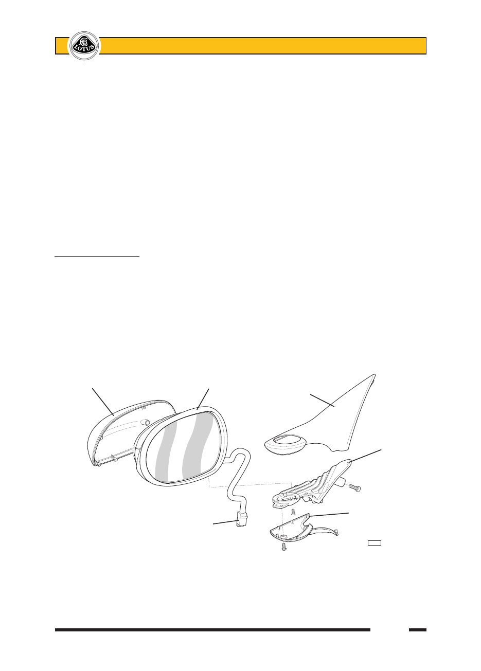
Replacement of mirror glass and cover
The mirror glass is contained in a plastic carrier which includes the heating element and terminals. To
remove the glass, press the glass so as to expose the outer edge, and carefully ease the outboard end from
its carrier clip. Then unhook the inboard end, unplug the two heater cables, and remove the glass. Check that
the adjustment racks have not become detached from the gimble during disassembly.
Mirror cover Mirror body Plinth upper
moulding
Cast alloy
plinth
Plinth lower
Harness connector moulding
b360