Lotus Elise / Lotus Exige. Instruction - part 106


  Index      Lotus     Lotus Elise / Lotus Exige (engine 1ZZ/2ZZ) - service repair instruction 2004 year


Search            


Content   ..  104  105  106  107   ..


Lotus Elise / Lotus Exige. Instruction - part 106


Lotus Service Notes                               Section WD

Page 19

Page 6a

Airbag Activation/Disposal Procedure

Items Required
2

People.

2 Pairs

Heat proof gloves.

2 Pairs

Eye protection glasses.

2 Pairs

Ear defenders.

Explosion container – a container to constrain the sudden inflation of the bag, may be mesh e.g. metal stillage,
but requires a lid.
Sandbags, - to keep lid closed.
12 volt power supply.
Various air bag & seat belt wiring connectors / small crocodile clips.
10 meters Detonation wire
Paint marker pen
Dustbin / recycling container.

Weather Conditions.
Calm, clear, dry day with very little wind.
Place power supply upwind of explosion.

Location.
Any isolated area.

Procedure.
·

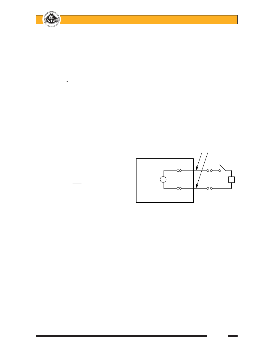
Circuit diagram as shown.

·

Make sure the power supply is turned off

and is situated the length of the detona-
tion wires away from the airbag.

·

Only detonate ONE at a time.

·

Ensure the detonation wires are discon-

nected from the power supply.

·

Place 1 airbag into the explosion con-

tainer and connect the detonation wires.
Do not snag wires.

·

Secure lid with sandbags.

·

Put on your Eye & Ear protection.

·

Connect the detonation wires to the power supply, doesn’t matter on polarity.

·

Turn the power supply on.

·

AIRBAG WILL DETONATE AND INFLATE.

·

Turn power supply off and disconnect detonation wires from the power supply.

·

Put on your heatproof gloves.

·

Remove the airbag from the explosion container and disconnect the detonation wires.

·

Mark-up and place the detonated airbag into the recycling container.

·

Repeat this procedure as many times as required.

Switch

Battery

Airbag

Detonation Wires

Cage


Lotus Service Notes                               Section WD

Page 7

the U.S. Dept, of Transportation (DOT) and most state governments. Special procedures are required for
transportation. Lotus recommends that the dealers and repair shops check with the hazardous material section
of their respective state police authority for applicable shipping requirements.

For all shipments on public roads, the DOT has classified the uninstalled inflator module as a flammable

solid under a special exemption process. It should always be shipped and stored in the approved cardboard
container in which it is purchased. The container should be marked with “Flammable Solid , n.o.s., UN1325,
DOT-E8236” and labelled with the specified red and white flammable solid label. Each shipping location must
have a copy of the exemption on file. A shipping paper (e.g., a customer receipt) must accompany each
shipment and identify the module as “Flammable Solid, n.o.s., UN1325, DOT-E8236”. Transportation, storage
and handling of the module should be in accordance with the exemption and the requirements for a DOT
flammable solid. Do not expose the module to heat, open flame, impact, friction, or electrical charge.

Inflator Module Scrapping Procedures

WARNING:  Failure to follow proper SRS inflator module disposal procedures can result in airbag
deployment which may cause personal injury. Undeployed inflator modules must not be disposed of
through normal refuse channels. The undeployed inflator module contains substances that can cause
severe illness or personal injury if the sealed container is damaged during disposal.  Disposal in any
manner inconsistent with proper procedures may be a violation of federal, state and/or local laws.

Reference should be made to the local State authority for the correct disposal procedures for deployed

inflator modules.

Vehicle Scrapping Procedures

Some vehicles equipped with SRS that have live (undeployed) inflator modules may have to be scrapped

because they have completed their useful life, or have been severely damaged in a non-deployment type
accident. The following procedure should be followed when scrapping a vehicle with an undeployed module.

1.

Follow the safety procedure detailed in sub-section WD.6 to turn off the ignition, disconnect the battery
and unplug the yellow 4-way connector to the inflator module, alongside the steering column.

2.

Follow the procedure detailed in sub-section WD.11 to gain access to the passenger airbag module.

3.

At the driver's airbag harness alongside the steering column, cut the harness side of the SRS wiring
approx. 3 to 6 inches from the yellow connector.

4.

Splice 2 wires at least 20 feet long to the red/blue and the red/green coloured cables in this connector
block.

5.

Reconnect the yellow 4-way connector block now equipped with 2 x 20ft long cables.

6.

Check that the inflator module is secured to the steering wheel.

7.

Remove all loose objects from the front seat.

8.

Ensure no one is in the vehicle.

9.

Stretch wires away from car to their full length.

10. Apply 12 volts across the wires to deploy the air bag.
11.

Do not touch the inflator module area for 20 minutes due to the heat generated during deployment.

12.

Wear gloves and safety glasses to handle the deployed air bag. Wash your hands with mild soap and
water afterwards.

13.

Repeat steps 3 to 12 for the passenger airbag, splicing the 20ft cables into the two wires connecting the
SDM to the airbag.

Deployed Inflator Modules

WARNING:  Safety precautions must be observed when handling a deployed inflator module. After
deployment, the air bag surface may contain a white packing powder used to ease deployment, to-
gether with a small amount of sodium hydroxide dust, a by-product of the sodium azide reaction
during deployment that can be irritating to the skin if left on for an extended period of time. Always
wear gloves and safety glasses when handling a deployed inflator module, and wash your hands with
a mild soap and water afterwards.


Lotus Service Notes                               Section WD

Page 8

Inspections Required After an Accident

All SRS system components, including harnesses and brackets, must be inspected after an accident. If

any are damaged or bent, they must be replaced even if a deployment did not occur. 

If the SRS was deployed,

the following components MUST be renewed even if there is no visible damage to the parts:
Driver airbag module;
Passenger airbag module;
Sensor & Diagnostic Module (SDM);
Driver and passenger pyrotechnic seat belt assemblies;
Rotary connector;
Passenger airbag mounting brackets (2);
Passenger airbag shute (2);
Passenger airbag door assembly (trim panel);
Dash panel upper extrusion.

Inspect the steering column for damage or telescoping (see Section HG) and column mounting brackets

for damage.  Inspect the chassis scuttle beam in the area of the passenger airbag mounting brackets for
damage or distortion.  Inspect the SRS wiring harness and connectors for damage or any signs of overheating.
Do not attempt to repair the steering column or chassis or any of the above mentioned components.  Service
is by replacement only.

WARNING:  Proper operation of the SRS system requires that any repairs to the vehicle structure
return it to its original production configuration. Deployment, or any visible damage to the SRS com-
ponents and/or their respective mounting brackets requires replacement, not repair.

WD.7 - THEORY OF OPERATION

The key components of the Supplementary Restraint System (SRS) are the following:

Sensor & Diagnostic Module (SDM);

Driver airbag module;

Passenger airbag module;

Rotary connector;

Seat belt pre-tensioners.

Sensor & Diagnostic Module (SDM)

The SDM is the main electronic control unit (ECU) of the SRS, whose function is to detect rates of forward

deceleration, and when interpreted as a collision accident requiring supplementary occupant protection, the
SDM triggers as a single set, the driver and passenger airbags and both seat belt pre-tensioners.  Additional
functions are to maintain an energy reserve in case of vehicle battery power interruption, operation of a dash
mounted tell tale lamp, and a electronic diagnostic and event recording facility accessible via a workshop
scanner tool.

The unit is mounted by a dedicated bracket to the top of the passenger side scuttle beam, accessible after

removal of the fascia top.

The following functionality is provided by the SDM;

Sensing of frontal impact crash events and vehicle specific discrimination between non-deployment and
deployment-requiring events as well as the deployment of the frontal airbags and seat belt pre-tensioners.

In case of a required deployment, timely activation of the activation current for the deployment loops.

Detection of electrical system faults which may influence the readiness of the system to deploy, or in-
crease the probability of an inadvertent deployment by:
- continuous electrical monitoring of all deployment circuits (without any effect on the readiness of the
system);
- continuous monitoring of the supply voltage and the lamp circuitry (dependent on lamp driver activation
status);
- SDM self test;
- activation of a tell tale lamp in case of a detected system fault.


Lotus Service Notes                               Section WD

Page 9

Fault storage and 'Crashrecording' within EEPROM ('crashrecording': recording of system parameters
(e.g. fault status in deployment events).

Diagnostic communication using an ISO9141 protocol.

Frontal Impact Sensing and Deployment

The SDM contains an integrated accelerometer which provides a nearly linear proportional electrical

representation of the acceleration experienced by the vehicle along the longitudinal axis.  This signal is ampli-
fied and filtered to reduce unwanted electronic noise and to compensate for offset drifts.  The filtered signal is
then digitized to provide an input for evaluation by the crash algorithm.  As soon as the crash algorithm detects
that pre-defined thresholds have been exceeded, the SDM activates both airbags and both seat belt pre-
tensioners.

To enhance system reliability under normal driving conditions, an additional electromechanical 'safing'

sensor is included to ensure that the SRS is armed only when significant deceleration occurs.  In order to
protect against undesired deployments in case of severe EMI, humidity or accelerometer fault, the decelera-
tion condition monitoring by the safing sensor occurs in addition to, and independent of, the crash algorithm.

Neither the seat belt pre-tensioners nor the airbags will be activated by the SDM as long as the diagnostic

mode is active.

Fault Display

The following conditions lead to a fault display in the form of continuous illumination of the airbag tell tale.

One or more trouble codes requiring tell tale lamp activation in the 'historic' and 'present' condition are
stored in the SDM's EEPROM.

One or more trouble codes requiring tell tale lamp activation in the 'present' condition only are stored in
the SDM's EEPROM, the condition of which is, or has been, 'present' in the current operating cycle.  For
all faults requiring four consecutive incidents for a trouble code to be set, the 'present' condition and fault
display will be activated already after two consecutive events if the related trouble code has already been
stored in a previous operating cycle.

Faults concerning the voltage supply (overvoltage/undervoltage) will lead to tell tale activation only until
the regular voltage range has been reached again (turn-off delay max. 5s after return from undervoltage
and max. 20s after return from overvoltage).  There are no related trouble codes.

The airbag tell tale will not be activated due to SRS warning lamp related faults.

The tell tale will be activated immediately after entering the diagnostic mode, or on deployment of the
SRS.

Excluding the exceptions stated above, it is not possible to switch off the tell tale other than by resetting

the fault codes stored in the EEPROM.  This is not possible after an airbag deployment - the SDM must be
renewed.

The following delays apply for the detection and display of faults.  The delays apply from the extinguishing

of the tell tale, following the ignition switch on bulb check period:
1 to 5 secs

- for external deployment circuit faults and overvoltage supply.

12 to 20 secs

- for undervoltage supply.

up to 15 secs

- for SDM internal faults.

The tell tale will be activated without SDM intervention in the following situations:

the minimum voltage of 8.0 V has not been exceeded after switching on the ignition.

the energy reserve (in SDM) has run low, which may be caused by supply voltages below 7.8 V.

the watchdog has interfered.

A trouble code readout using tell tale blink codes is not implemented.

Power Supply & Grounding

The nominal supply voltage of +12 volts is derived from terminal 5 when the ignition is switched on.  The

SDM internal ground (terminal 7) must be securely connected to the vehicle chassis ground.  To provide
redundant grounding, the SDM housing is internally connected to the ground connector pin.

Supply Voltage Range

The SDM is designed to operate within the following voltage ranges:


Content   ..  104  105  106  107   ..