Lotus Elise / Lotus Exige. Instruction - part 54
Lotus Service Notes Section HG
Page 12
8.
Fit the lower u/j pinch bolt, and tighten to 35 Nm.
9.
Fit the track rod ends into the steering arms, and tighten the nuts to 30 Nm.
10.
Check and adjust the front wheel alignment as detailed in sub-section CI.2.
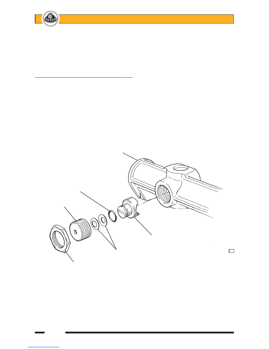
HG.7 - ADJUSTMENT OF RACK BAR THRUST PAD
The following information applies to one-piece alloy bodied steering rack units:
A thrust pad backed by a pair of belleville washers, is used to control the preload between the rack bar
teeth and the pinion gear, and is adjustable via a threaded backstop plug. The correct preload allows the
horizontally mounted rack bar (column disconnected) to be pulled through its full travel by a steady force of 50
- 70 N (12 - 16 lbf). The rack and pinion assembly must be removed from the chassis before any adjustment
may be carried out.
To adjust the thrust pad, release the locknut (36mm socket) and use a 5.5mm hexagonal bit to adjust the
backstop as required before tightening the locknut. For an approximate initial setting, screw in the backstop
plug until solid, then back off ½ turn.
The following information applies to alloy/steel tube type steering rack units:
A thrust pad backed by a coil spring, is used to control the preload between the rack bar teeth and the
pinion gear, and is adjustable via a threaded backstop plug. The correct preload allows the horizontally mounted
rack bar (column disconnected) to be pulled through its full travel by a steady force of 50 - 100 N (12 - 20 lbf).
The rack and pinion assembly must be removed from the chassis before any adjustment may be carried out.
To adjust the thrust pad, release the locknut (36mm socket) and use a 19mm hexagonal bit to adjust the
backstop as required before tightening the locknut. For an approximate initial setting, screw in the backstop
plug until solid, then back off ¼ turn.
Rack housing
'O' ring
Threaded plug
Thrust pad
Belleville washers
h56
Locknut