Lotus Eleven/Elise/Exige. Instruction - part 63


  Index      Lotus     Lotus Eleven/Elise/Exige (engine 1ZZ/2ZZ/1ZR) - service repair instruction 2004 year


Search            


Content   ..  61  62  63  64   ..


Lotus Eleven/Elise/Exige. Instruction - part 63


   Lotus Service Notes

                Section JJ

Page 5

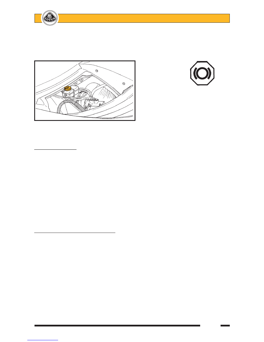
If the reservoir needs topping up, first clean around the cap to reduce the possibility of contamination

before unscrewing the cap;  it is not necessary to disconnect the level sensor cables.  Take suitable precautions
to guard against damage to paintwork caused by brake fluid dripping from the level sensor.  Use only a fresh
supply of DOT 4 non-mineral type fluid, identified by a yellow and black symbol.

Do NOT use DOT 5 silicone fluid, or any

fluid which has been exposed to the atmos-
phere for more than a brief period, or any fluid
suspected of being wet, dirty or contaminated.
Do not overfill.  Replace the filler cap securely.

Some service operations, such as replacing brake pads, will result in the displacement of fluid from the

hydraulic circuit back into the reservoir.  In order to prevent fluid overflowing from the reservoir, it may be
necessary to remove some fluid using a syringe.

Renewal of Brake Fluid

Brake fluid absorbs water from the atmosphere over a period of time (hygroscopical), resulting in a

lowering of the boiling point of the fluid, and corrosion of the hydraulic system.  For optimum safety and brake
performance, the brake fluid should be renewed every twelve months (including clutch release system).

Brake Bleeding Procedure

If the brake fluid is to be renewed, or an hydraulic component replaced, the system should be bled of air

using the following procedure:
1.

Using conventional instruction techniques, or low air pressure applied to the reservoir, bleed the system
from each calliper bleed nipple in turn until no air bubbles can be seen.

2.

Connect the Lotus Scan tool and select ABS and follow the brake bleeding instructions.  Whilst this
automatic process is taking place (with all 4 calliper nipples open), gently cycle the brake pedal up and
down whilst keeping the reservoir topped up, to move any air bubbles displaced from the ABS unit down
the hydraulic lines.  Finish by closing each nipple with the pedal down.

3.

Repeat step (1) to purge each calliper feed line in turn.

JJ.4 - FRONT BRAKE PAD REPLACEMENT

Pad thickness may be checked with the wheel removed without disturbing the calliper.

Standard pad thickness (excluding backplate);

9.0 mm

Minimum pad thickness (excluding backplate);

2.5 mm

If the thickness of any pad is below the specified minimum, the axle set of pads should be renewed.  Note

that the pad backplates are factory fitted with anti-squeal overlays, and are identified with T 4139 on the
backplate.

For cars used on track, where sustained hard use and extreme brake temperatures are likely to occur,

'Motorsport' pads made by Pagid may be fitted in complete vehicle sets under part number A111J0150S (front)
and A111J0151S (rear).

1.

To remove the brake pads;  Remove the 'R' clip from the lower of the two pad retaining pins, and withdraw
the lower of the pin taking care to restrain the anti-rattle spring.  Remove the second retaining pin to-
gether with the anti-rattle spring plate.  Withdraw the pads from the calliper.  Measure the lining thickness
and renew the axle set of pads if any lining is below 2.5 mm.

j146

BRAKE FLUID

ohs139

RESERVOIR
CAP

Non-mineral type
brake fluid symbol
(Yellow & Black)


   Lotus Service Notes                                  Section JJ

Page 6

2.

Before replacing the pads, inspect the calliper for any signs of fluid leakage from a piston seal or joint,
and replace the calliper if any such signs are evident.  Clean the pad recess in the calliper taking suitable
precautions to protect from dust inhalation.

3.

If refitting the existing brake pads, refit each pad in the same position as originally fitted.

4.

If fitting new pads, the pistons must be pushed back into the calliper to provide the necessary clearance.
This action will return fluid to the master cylinder such that some fluid may need to be removed in order
to prevent overflowing.  Take care to avoid damaging the brake disc surface, or distorting the disc.

5.

Position the pads in the calliper, and insert the upper pad retaining pin from the outboard side.  Secure
with the split pin.

6.

Fit the anti-rattle spring into position with the side tangs pressing against the top end of the pad backplates,
and the centre tang beneath the retaining pin.  Insert the second pad retaining pin into the calliper,
passing over the lower central anti-rattle spring tongue.

7.

Before driving the car, press the brake pedal several times to bring the pads to their correct running
position.   Top up the master cylinder reservoir if necessary to bring the level to the top of the 'MAX' mark.

8.

Ensure the customer is made aware that maximum braking efficiency will be achieved if, for the first few
hundred miles, needless heavy braking is avoided, and the brake pads are allowed to 'bed in' fully before
being used to their full potential.

JJ.5 - REAR BRAKE PAD REPLACEMENT

Pad thickness may be checked after removing the road wheel, without disturbing the calliper.
Standard pad thickness (excluding backplate);

6.5 mm

Minimum pad thickness (excluding backplate);

2.5 mm

If the thickness of any pad is below the specified minimum, the axle set of pads should be renewed.  Note

that the pad backplates are marked T 4139 and are factory fitted with anti-squeal overlays.

'R' pin

Brake pad

Pad securing pin

Anti-rattle spring plate

         j164

   Lotus Service Notes

                Section JJ

Page 7

Tools Required:

Piston Retraction Tool   T000T1242

1.

Remove the rear road wheels.

2.

At each rear corner: using a suitable pin
punch, knock the pad retaining pin out
of the calliper towards the outside, tak-
ing precautions as necessary to restrain
the anti-rattle spring from flying off as
the pin is withdrawn.

3.

Remove the anti-rattle spring, and with-
draw both brake pads from the calliper.
Measure the thickness of the lining ma-
terial, and renew the axle set of pads if
any are below 2.5 mm.

4.

Before refitting the pads, inspect the pis-
ton boot for splits, cracks or other dam-
age, and for any signs of fluid leakage
or wetness.
If any such signs are apparent, the complete calliper should be replaced as Brembo do not recommend
that this calliper be dismantled.

5.

If refitting the existing brake pads, refit each pad in the same position as originally fitted.

6.

Before fitting new rear pads, the calliper piston must be screwed back into the calliper down the parking
brake actuation mechanism.  This operation requires the use of special tool T000T1242 and the removal
of the brake disc:
-

Remove the single socket head screw retaining the brake disc, and remove the disc.

-

Fit special tool T000T1242 into the holes in the calliper piston, and screw the piston back down
the parking brake mechanism screwthread until fully bottomed.

-

Refit the brake disc, and tighten the countersunk retaining screw to 12 Nm.

7.

In order to minimise brake squeal from new pads during the bedding-in period, a copper based (PBC)
paste (e.g Renolit) should be used on the pad contact surfaces of the rear callipers in the areas shown:

Pad retaining pin

Retaining
pin snap
ring

       Anti-rattle spring

      j123

Contact face of piston

Calliper outboard fingers

188


   Lotus Service Notes                                  Section JJ

Page 8

8.

Slide the brake pads into the calliper.  Position the pad anti-rattle spring in the calliper aperture, with the
spring ends located in the recesses provided.  Ensure that the spring is fitted the correct way up, w i t h
the turned spring end in the longer recess.  Press the spring eyes into alignment whilst the pad retaining
pin is inserted through the calliper from the outside.  Ensure that the pin passes through both eyes of the
anti-rattle spring, and both brake pads, and that the pin is fully installed with the snap ring seated in the
outboard side of the calliper.

9.

Refit the roadwheels and press the brake pedal several times to set the brake pad position.  Before
switching on the ignition, check the fluid level in the reservoir and top up if necessary.

10.

Ensure the customer is made aware that maximum braking efficiency will be achieved if, for the first few
hundred miles, needless heavy braking is avoided, and the brake pads are allowed to ‘bed in’ fully before
being used to their full potential.

Top surface of bridge including

Bottom surface of bridge

inner surface in contact with

including inner surface

pad backplate

in contact with pad backplate

         j188

Anti-rattle spring

Inboard pad

Turned spring end
in longer recess

Outboard pad

Pad retaining pin

        j124


Content   ..  61  62  63  64   ..