Lotus Eleven/Elise/Exige. Instruction - part 60


  Index      Lotus     Lotus Eleven/Elise/Exige (engine 1ZZ/2ZZ/1ZR) - service repair instruction 2004 year


Search            


Content   ..  58  59  60  61   ..


Lotus Eleven/Elise/Exige. Instruction - part 60


Lotus Service Notes                                  Section HG

Page 6

The upper steering column assembly comprises an inner column which connects the steering wheel to the 

intermediate shaft, and a tubular steel outer column which, with its alloy upper bearing housing, supports the 

inner column and carries the column lever switches for lighting and wiper control, and also the ignition switch/

steering lock.

Both inner and outer columns are of fixed length, but are telescopically collapsible when subjected to 

crash forces.  The two parts of the inner column are fixed together by plastic pins designed to shear and allow 

telescoping to occur beyond a specified axial load.  The two part outer column tube uses gripper rings to retain 

the column length, with the lower part mounted by a single fixing to the chassis scuttle beam via a three point 

fixing steel bracket.  The upper part of the outer column has two open slotted mounting flanges each of which 

is fitted with a 'break out' alloy insert, bolted through to an extruded alloy plinth fixed to the scuttle beam.  In 

the event of an extreme axial load being applied to the column via the steering wheel, as may occur during a 

vehicle frontal collision, the plastic retaining pins in the column flange inserts will shear and allow the upper 

part of the column to break free of the upper fixings and telescope forwards, reducing the potential for column 

induced injury.


Dimensional Check

If the vehicle is involved in an accident, or any part of the column is subjected to an abnormal load includ-

ing airbag deployment, the column should be carefully examined to establish if any telescoping has occurred.  

Perform the following checks, and replace the complete upper column assembly if any of the dimensions are 

outside specification:

1.  Outer Column:


Measure the length of the lower part of the outer column as shown:


Specification = 80 ± 1mm

2.  Inner Column lower:


Measure the length of the exposed part of the inner column as shown:


Specification = 58 ± 1mm
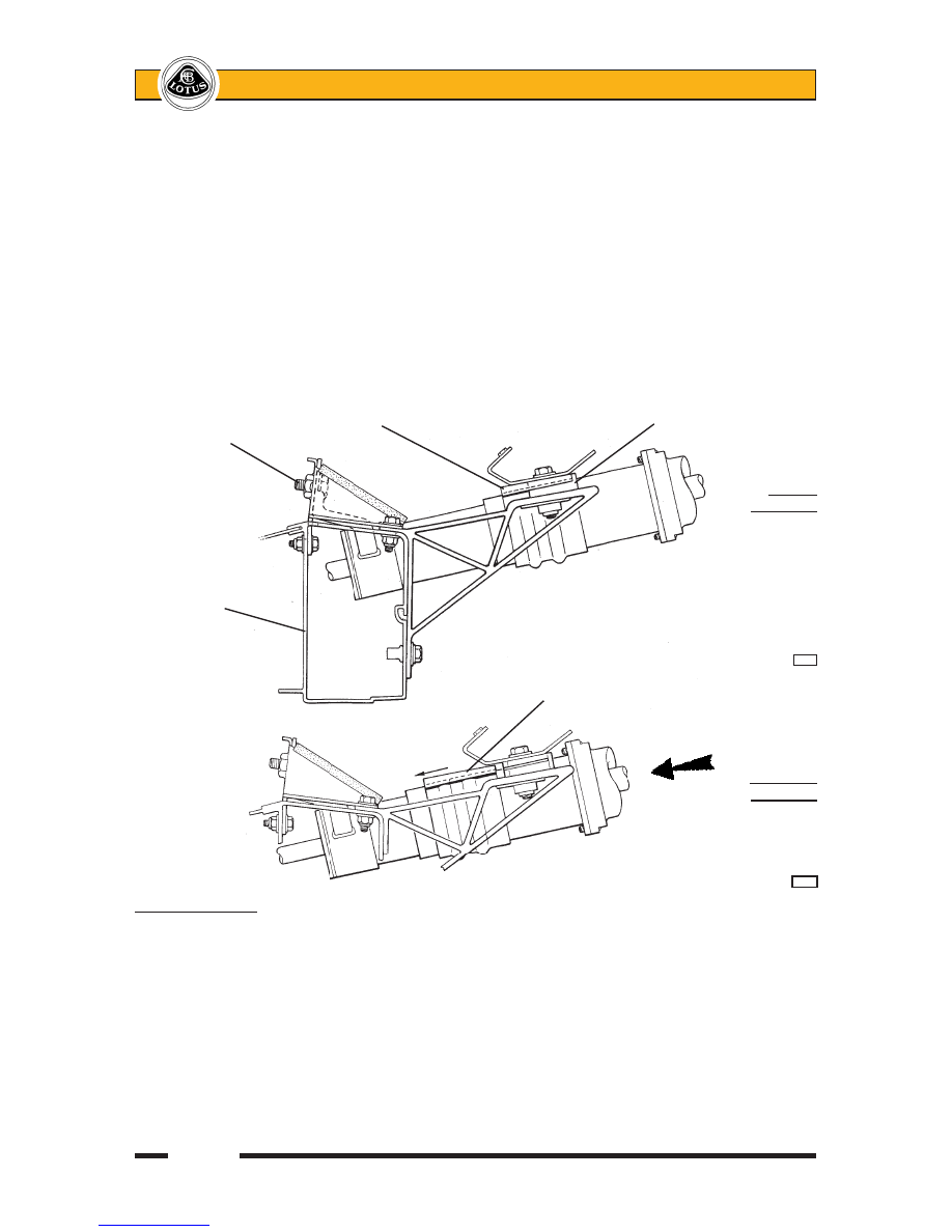


Column slotted    


'Break out'


flange 


insert


Column


lower 


fixing

Normal

Condition


Chassis


scuttle


beam  


        h50a


Column flange broken


out of insert

Collapsed 

Condition


h51a


Lotus Service Notes                                  Section HG

Page 7

3.  Inner Column Upper


With  the  steering  wheel  removed,  measure  the  length  of  the  exposed  part  of  the  upper  column  as 

shown:


Specification = 76 ± 1mm

4.  'Break out' Inserts


Remove  the  column  shrouds  and  the 

column  flange  fixing  bolts,  and  check 

that each of the alloy 'break out' inserts 

is securely attached to the column flange.  

If the plastic pins are sheared, the column 

assembly must be replaced. 

Outer  


Inner 

column 


column

assembly   


lower end


     80 ± 1 mm   


     58 ± 1 mm   


h52

Inner column

upper end


    76 ± 1 mm


                    h52a

Alloy 'break

out' insert

Nylon 

shear

pins


h48


Lotus Service Notes                                  Section HG

Page 8

To Remove Upper Steering Column Assembly

WARNING:  On cars so equipped, the driver's airbag is housed in the hub of the steering wheel.  Precau-

tions need to be taken for personal safety when working with airbags and associated componentry.  Do 

not attempt to remove the airbag, steering wheel or column without first referring to section WD. 

1.  Disconnect the battery, and remove the column shrouds (see sub-section HG.2).

2.  Disconnect the column lever switches, or release the retaining pawls and slide the switches out of the 

carrier.  Disconnect the horn contact pin.  On airbag equipped cars, refer to section WD and unplug the 

yellow airbag harness connector.

3.  To disconnect the ignition switch: prise open the terminal cover, and use a small screwdriver to release 

the retaining barb located between the white and yellow cables.  Withdraw the connector.

4.  If necessary, remove the steering lock/ignition key barrel: Turn the key to position 'I', depress the spring 

pin accessible via a hole in the column switch carrier, and withdraw the lock barrel.

5.  If necessary, remove the ignition switch: First remove the steering lock/ignition key barrel (see above).  

Remove the retaining grub screw and withdraw the switch.

6.  If necessary, remove the steering lock assembly: Remove the spline head screw securing the column 

switch carrier, and drill or chisel out the two shear head bolts fixing the lock assembly to the column.

7.  Remove  the  pinch  bolt  securing 

the  upper  universal  joint  to  the 

intermediate column.

8.  On  non-airbag  cars,  remove  the 

two fixings for the instrument pack 

mounting  brackets,  and  remove 

the instrument pack and cowl as-

sembly after unplugging the single 

harness connector.


On airbag equipped cars, withdraw 

the instrument surround and cowl 

straight rearwards from the dash 

panel to release the spring clips.  

Remove  four  screws  to  release 

the  instrument  pack  mounting 

bracket from the dash and unplug 

the two harness connectors

9.  Release the two bolts securing the 

upper column clamp to the dash 

brackets, and remove the switch 

pack.

10.  From  the  access  provided  by 

the  removal  of  the  switch  pack, 

release the upper column single 

lower  fixing  and  withdraw  the 

column assembly from the scuttle 

and off the intermediate steering 

column.


Non-airbag type shown


Instrument cowl

Instrument 

pack


Instrument 


& cowl


mounting


bracket


                   b259a


Lotus Service Notes                                  Section HG

Page 9

11.  Refit the column in reverse order to removal with the following notes:

The groove for the pinch bolt allows assembly of the universal joint to the intermediate column in only one 

orientation.  Torque tighten the pinch bolt to 35 Nm.

Torque tighten the column lower fixing bolt to 45 Nm

Torque tighten the two column upper fixing bolts to 22.5 Nm.

If applicable, use new shear bolts to secure the steering lock assembly, and tighten until sheared.

HG.4 - INTERMEDIATE COlUMN

The intermediate steering column consisted of a symmetrical splined shaft and two different Hookes type 

universal joints, but has now been replaced by a shaft with an integral lower u/j.  The lower joint uses an un-

indexed 36 spline connection to the steering rack pinion shaft, and the upper joint accommodates a double flatted 

boss on the end of the upper column, with a pinch bolt groove allowing assembly in only one orientation.  The 

intermediate shaft itself, uses a splined joint, and, on early type shafts, a lower indexed pinch bolt groove.

To remove the intermediate column assembly, the upper column must first be removed (see sub-section 

HG.3), after which the rack pinion shaft pinch bolt may be removed and the column assembly withdrawn.  Match 

marking the lower u/j to the pinion shaft will aid steering wheel alignment on re-assembly.  Torque tighten the 

pinch bolts to 35 Nm.

HG.5 - TRACK ROD ENDS & RACK GAITERS

Front Wheel Alignment

Alignment is measured either by the angle a wheel makes with the vehicle centre line, or the difference in 

dimension between the wheel rim to wheel rim measurement at the front and rear of the wheel at hub centre 

height.  The wheels are said to 'toe-in' when the wheel paths converge ahead of the vehicle, and 'toe-out' when 

they diverge.  Wheel alignment is designed to vary with both steering angle (Ackermann) and suspension travel 

(bump steer) and should be measured only 'straight ahead' at the specified ride height.

Airbag Type 

 Instrument pack


Instrument cowl   


Instrument 


mounting bracket


fixings (4 off)


Upper column clamp fixings   


b343


Content   ..  58  59  60  61   ..