Lotus Eleven/Elise/Exige. Instruction - part 55


  Index      Lotus     Lotus Eleven/Elise/Exige (engine 1ZZ/2ZZ/1ZR) - service repair instruction 2004 year


Search            


Content   ..  53  54  55  56   ..


Lotus Eleven/Elise/Exige. Instruction - part 55


Page 13


Lotus Service Notes   


     Section FJ

11.  Fit the new lift tube adaptor onto the gear lever and ensure it is free to slide up and down.  Hook in the 

reverse selector cable and secure to the gear lever abutment.  Temporarily fit the new lift tube onto the 

adaptor and screw on the new gear knob.  Adjust the cable to allow correct reverse gear selection and 

tighten adjuster nuts.  Remove gear knob and lift tube.  Clip the selector cable onto the gear lever ball.

12.  Cut the tie strap securing the old lift tube in the gear lever gaiter and fit the new lift tube using a suitable tie 

strap.  Fit the shroud over the parking brake and gear lever, taking care not to scratch the surface finish,  

and aligning the flats on the lift tube with those on the lift tube adaptor.  Connect the electrical switches as 

necessary, and retain the shroud with the two screws.

13.  Use the new spring clip to secure the lift tube to the adaptor, and fit the new gear knob, tightening the grub 

screw to orientate the graphic correctly.  Fit and secure the parking brake lever sleeve.

14.  Check gear selection and reverse inhibit function.  Ensure the lift tube returns freely under spring action.

FJ.3 - LUBRICATION

The transmission should be checked for oil leaks, for the correct oil level, and the oil renewed, at intervals 

specified in the Maintenance Schedule.

Transmission oil viscosity;  SAE 75W/90

Specification;          API GL-4 or GL-5

Quantity; - 6 speed  C64    2.3 litres

      - 6 speed EC60   2.4 litres

      - 5 speed       1.9 litres

To check the oil level: 

Remove the engine bay undertray.

Wipe clean the area around the socket 

headed level plug on the front face of the 

transmission main casing.

Remove the plug, and check that the oil 

is level with the bottom of the hole.  Note 

that the release of oil trapped by the plug, 

should not be confused with an indication 

of correct oil level.

- If  necessary,  add  only  the  specified 

lubricant (see above) via the level plug hole 

until the oil level stabilises at the bottom of the 

plug hole.  

Alternatively, oil may be added into the 

top  of  the  transmission  via  a  mechanical 

speedo  drive  (not  used  in  this  application) 

cover at the right hand top of the transmission, 

after removing the single screw.   

- Refit the level plug with a new sealing 

washer, and tighten securely.

To renew transmission oil:

The hexagon headed drain plug located at the bottom of the final drive casing, should be removed im-

mediately after a run when the oil is warm, taking suitable precautions against scalding.  

Clean the plug, fit a new sealing washer and refit securely.

Refill to the level plug hole as detailed above.
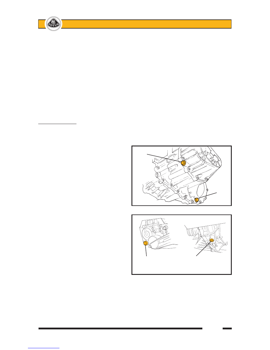
 C64 filler/level

  plug


                              C64

                                      Drain

                                     plug


 f131

  EC60 

 filler/level

  plug in end case

f147

  EC60 

  drain plug 

  in underside


Lotus Service Notes   


     Section FJ

Page 14

FJ.4 - DRIVE SHAFTS

Each of the two driveshaft assemblies comprises a steel shaft with a constant velocity joint at each end, 

and is used to transmit the drive from each differential output gear to the rear wheel hub.  The two driveshaft 

assemblies are similar, but on C64 transmissions, the inboard joint of the right hand shaft is supported in an 

outrigger bearing bolted to the right hand side of the cylinder block, and uses an integral extended shaft to 

reach into the transmission housing.  The inboard joints are of a plunging 6-ball double offset design to ac-

commodate driveshaft length variation with suspension travel, whereas the outboard joints are high efficiency 

8-ball fixed type.

Replacement outboard joints include the main driveshaft (longer on the RH side), outboard C.V. joint and 

gaiter.  Replacement inboard joints include the inner C.V. joint and gaiter kit, with the C64 type extended stub 

shaft of the RH joint also including the support bearing and mounting bracket.

The joints themselves are packed with grease on initial assembly, and are maintenance free.  It is however 

vitally important that the protective gaiters are carefully inspected at service intervals, to check for splits, tears 

or punctures, since the joint will deteriorate very quickly once contaminated with dirt or water.  Damaged gaiters 

should be renewed immediately, once the servicibility of the joint has been established.

CAUTION:  The outboard C.V. joint gaiter can suffer 'pinch' damage if the joint is subjected to extreme articula-

tion off the car, or during driveshaft removal/refitment.

RH Driveshaft Assembly


f128

    Outboard joint       Main shaft            Inboard joint          Extension shaft

                                                        (C64 only)

                                                Support bearing

LH Driveshaft Assembly


f129

      Outboard joint           Main shaft          Inboard joint      Circlip   

Page 15


Lotus Service Notes   


     Section FJ

Clicking noises, torque reversal 'clonks', or shudder and vibration when accelerating are all possible symp-

toms of worn C.V. joints.  It should not be possible to discern any free play in a joint, but care must be taken not 

to confuse this with transmission backlash, which will certainly be evident.  Any symptoms that could be due to 

worn driveshaft joint assemblies, should be investigated and rectified without delay, since a broken driveshaft 

can cause considerable damage.  Safety considerations should always be accorded the highest priority.

The inboard C.V. joint is equipped with a male splined spigot shaft which engages with the female splines 

of the differential output sun gear, with the LH shaft retained by a round section spring circlip on its end, and 

the RH shaft retained by the extension shaft support bearing.  Each of the two transmission output oil seals 

runs on a stepped shoulder on the C.V. joint spigot shaft.  The stub shaft of each outboard joint is splined into 

the wheel hub, and retained by a nut on the threaded end of the shaft.

Driveshaft Assembly Replacement

Removing a driveshaft assembly from the transmission will result in some loss of transmission lubricant.  

It may be preferred to drain off some oil via the transmission drain plug beforehand.

1.  Remove transmission drain plug and drain off approx. 1 litre of oil into a clean container for re-use.

2.  Remove the rear road wheel.

3.  Remove the split pin from the hub nut and remove the nut and washer (right hand thread on both sides).   

Before the shaft can be withdrawn from the hub, the top ball joint plinth must be released from the hub 

carrier (note camber shims fitted), and the toe-link ball joint separated from the carrier.  This will allow the 

hub carrier to be pulled away sufficiently for the driveshaft to be withdrawn, but take care not to strain the 

brake hose or wheel speed sensor harness.

4.  Except C64 RH Driveshaft:  The driveshaft inboard joint is retained in the transmission by a round section 

circlip.  The joint may be removed by applying a shock pull to the C.V. joint body using a slide hammer 

with a forked end. 


CAUTION:  Do NOT attempt to remove the inboard C.V. joint from the transmission by pulling on the 

driveshaft.  The balls of the inboard joint are restrained for transit purposes only, by a circlip at the end of 

the ball tracks.  Applying an extension force to the joint will damage the balls and require joint replacement.  

Apply pressure only to the outer body of the joint.


C64 RH Driveshaft:  This driveshaft incorporates a bearing for the extension shaft and it is this which 

retains the shaft in the transmission.  Remove the two bolts securing the bearing bracket, and withdraw 

the complete shaft assembly.


When withdrawing either driveshaft from the transmission, take care not to damage the output oil seal.

6.  Before re-fitting a driveshaft, first renew the round section circlip on the end of the inboard joint spigot shaft, 

and lubricate the circlip with grease.  Also, check the condition of the transmission output seal, and renew 

if necessary.  Lubricate the lip of the seal with transmission oil, and grease the corresponding shoulder 

on the driveshaft (C.V. joint) spigot, to reduce the danger of damaging the seal on assembly.  

7.  Carefully insert the driveshaft into the transmission, with the two ends of the circlip positioned lowermost, 

and rotate the shaft if necessary to engage the splines.  Press the inboard joint outer until a click indicates 

the engagement of the retaining circlip, if necessary using a brass drift and hammer.  Afterwards, pull on 

the joint body to check its security.  On the C64 right hand shaft, fit the bolts securing the extension shaft 

bearing to the engine mounted bracket, and torque to 64 Nm.

8.  Fit the outer end of the shaft into the hub, and refit the top ball joint plinth to the hub carrier with the cam-

ber adjustment shim pack in position.  Apply Permabond A130 (A912E7033V) to the threads of the  two 

socket head bolts and torque to 45 Nm.  

9.  Refit the toe-link into the hub carrier and torque the retaining nut to 55 Nm.

10.  Fit the washer and castellated nut to the driveshaft, apply the parking brake and tighten the nut to 220 

Nm.  Fit a new split pin to lock the nut. 


11.  With the car on a level surface, top up the transmission oil to the filler/level plug hole.


Lotus Service Notes   


     Section FJ

Page 16

Driveshaft C.V. Joint and/or Gaiter Replacement

The outboard C.V. joint is supplied complete with main driveshaft to which it is fixed by a spline with a small 

helix angle to eliminate any potential backlash.  Separation of the shaft from the joint should not be attempted.  

Note that the RH main shaft is 22mm longer than the LH shaft.  Replacement of the outboard joint gaiter entails 

removal of the complete driveshaft assembly from the car, and removal of the inboard joint from the shaft.

1.  Remove the driveshaft assembly from the car (see above).

2.  Remove the clips securing the inboard joint gaiter without damaging the gaiter if it is to be re-used.  Pull 

the gaiter off the joint outer body, remove the circlip in the end of the joint outer body and match mark the 

body to the joint inner race before sliding the body off the shaft assembly.

3.  Remove the circlip from the end of the shaft and match mark the inboard joint inner race to the shaft before 

pulling or pressing the race from the shaft.  Slide the inboard gaiter off the shaft.

4.  Remove the clips securing the outboard gaiter, and slide the gaiter off the shaft.

5.  Inspection & Cleaning:  Complete disassembly of either joint is NOT recommended.  The separate com-

ponents are a precision fit and develop their own individual wear patterns, such that any interchanging or 

re-orientation of parts is likely to result in premature failure.


If the grease in the joint is contaminated with dirt or water, it is likely that the joint is damaged, and should 

be replaced.  If the grease is not contaminated, the joint should be degreased by soaking in a suitable 

solvent (NOT petrol), and then carefully inspected.  Tilt the inner race to one side to expose each ball.  

Severe pitting, galling, play between ball and its cage window, any cracking or damage to the cage, or 

pitting, galling or chips in raceways, call for joint replacement.


If the joint is found to be serviceable, it must be repacked with the special grease provided.  Pack the 

grease into the joint itself and also into the inside of the new gaiter.


NOTE: The grease provided in the kits is specially formulated for wear resistance and durability.  DO NOT 

use substitutes or mix with other lubricants.  The grease specification and quantity also differs for inboard 

and outboard joints:


Inboard: 140g    NKG 205    99-1089#BJ95


Outboard: 130g    NTG 2218M   99-729#BJ100 (inboard grease is also supplied as the inboard joint must 

be removed before fitting outboard gaiter)

6.  Slide the new outboard gaiter and smaller retaining clip onto the shaft. Fit the gaiter into the grooves on 

the outboard joint body and the driveshaft, and secure with the clips provided.

7.  Slide the new outboard gaiter and retaining clip onto the driveshaft and press the joint inner race onto the 

driveshaft splines with the match marks aligned (if re-using joint).  Retain with a new circlip. 

8.  Fit the inboard joint body to the shaft assembly with the match marks aligned (if re-using joint), and fit a 

new circlip into the end of the housing to retain the joint.

9.  Fit gaiter into the grooves on the joint outer body and driveshaft and secure with new gaiter clips.

10.  Refit the driveshaft to the car (see above).

Extension Shaft Support Bearing - C64

The ball bearing supporting the RH driveshaft extension shaft to the engine block is mounted in a housing 

which is bolted to a bracket on the engine block.  The bearing is sealed and maintenance free, and is included 

as part of the inboard C.V. joint assembly, but may if necessary be renewed by the following procedure:

1.  Remove the RH driveshaft assembly (see above).

2.  Using a press, remove the dust shield from the inboard end of the shaft.

3.  Remove the circlip from the outboard face of the bearing housing, and press or pull the housing from the 

bearing.


Content   ..  53  54  55  56   ..