Airbus A318. AIRCRAFT CHARACTERISTICS AIRPORT AND MAINTENANCE PLANNING (2016) - page 3
@A318
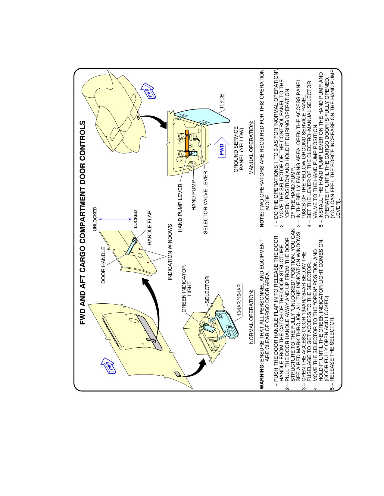
AIRCRAFT CHARACTERISTICS - AIRPORT AND MAINTENANCE PLANNING
**ON A/C A318-100
A
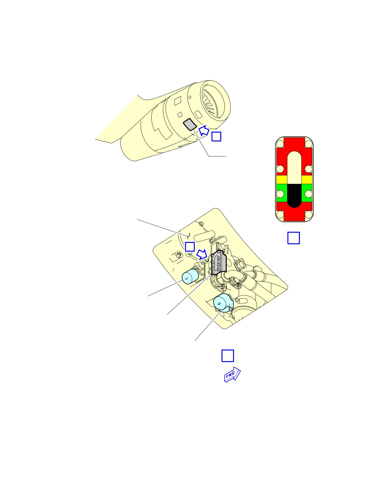
438DR (ENGINE 1)
OVER FULL
448DR (ENGINE 2)
ADD
ADD
OIL
OIL
IDG
B
B
IDG OVERFILL
DRAIN VALVE
IDG OIL LEVEL
SIGHT GLASS
IDG PRESSURE
FILL VALVE
A
N−01198 (0601)
PW V
N_AC_050408_1_0070101_01_00
Ground Service Connections
IDG Oil Tank -- PW6000 Series Engine
FIGURE-5-4-8-991-007-A01
Page 9
May 01/16
5-4-8
@A318
AIRCRAFT CHARACTERISTICS - AIRPORT AND MAINTENANCE PLANNING
**ON A/C A318-100
A
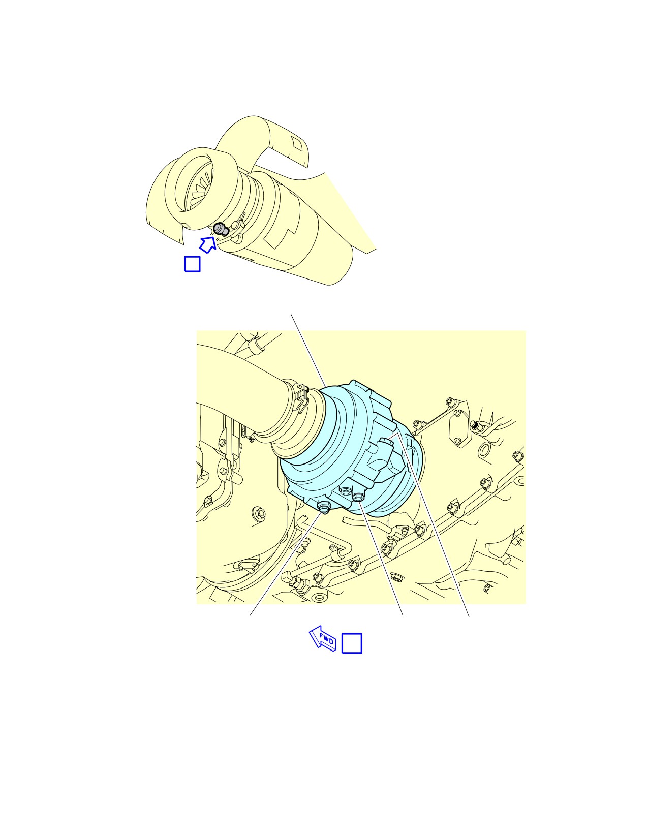
STARTER
MAGNETIC
OVERFLOW
FILL
CHIP COLLECTOR
PLUG
PLUG
N−01199 (1100)
A
PW V
N_AC_050408_1_0080101_01_00
Ground Service Connections
Starter Oil Tank -- PW6000 Series Engine
FIGURE-5-4-8-991-008-A01
Page 10
May 01/16
5-4-8
@A318
AIRCRAFT CHARACTERISTICS - AIRPORT AND MAINTENANCE PLANNING
**ON A/C A318-100
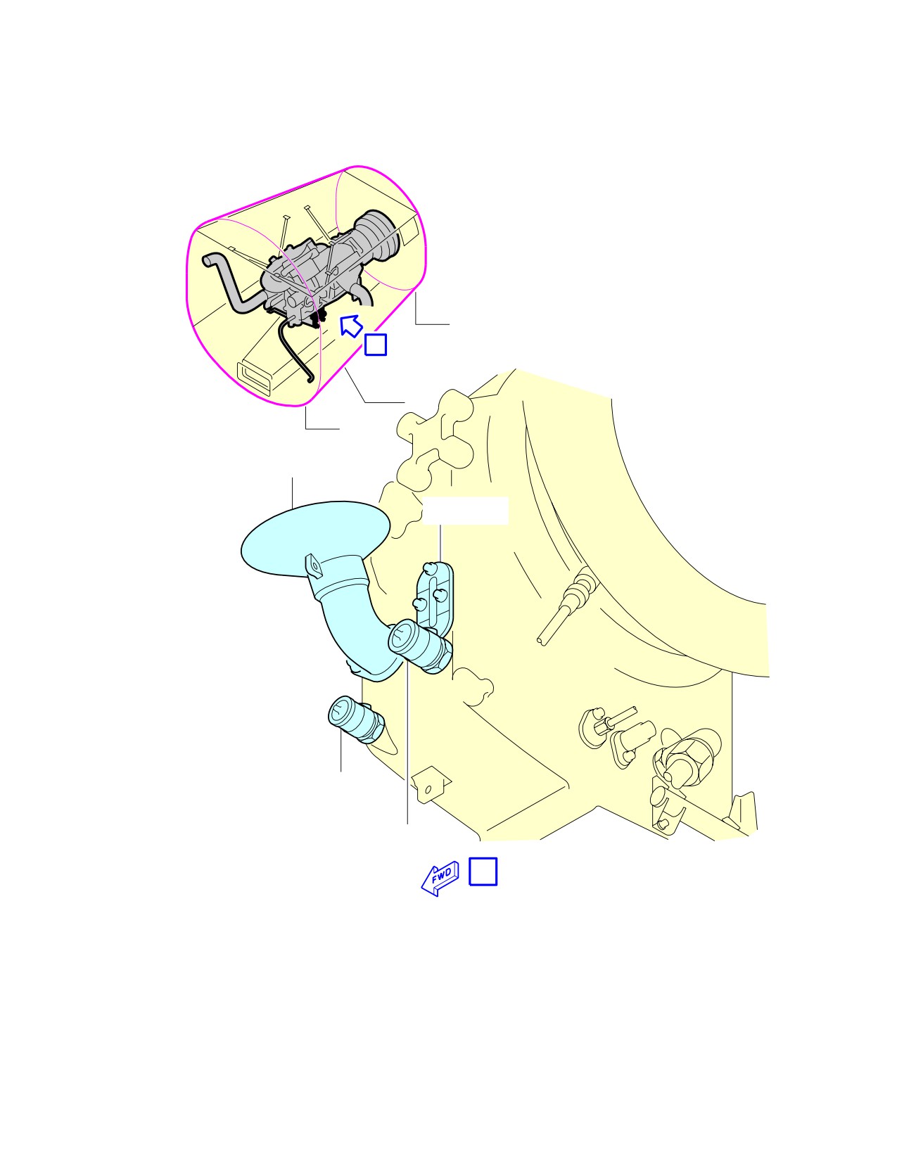
FR84
A
Z315
(Z316)
FR80
GRAVITY
OIL FILLER
OIL LEVEL
SIGHT GLASS
PRESSURE
FILL PORT
OVERFLOW
DRAIN VALVE
A
N_AC_050408_1_0090101_01_00
Ground Service Connections
APU Oil Tank
FIGURE-5-4-8-991-009-A01
Page 11
May 01/16
5-4-8
@A318
AIRCRAFT CHARACTERISTICS - AIRPORT AND MAINTENANCE PLANNING
5-4-9
Potable Water System
**ON A/C A318-100
Potable Water System
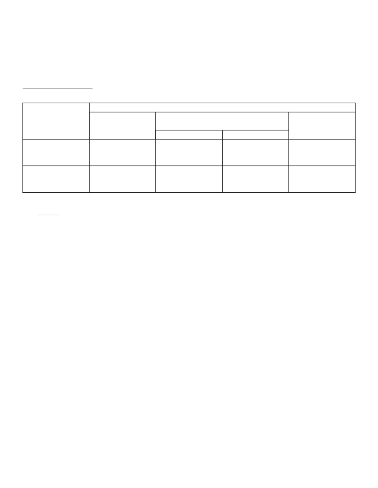
1.
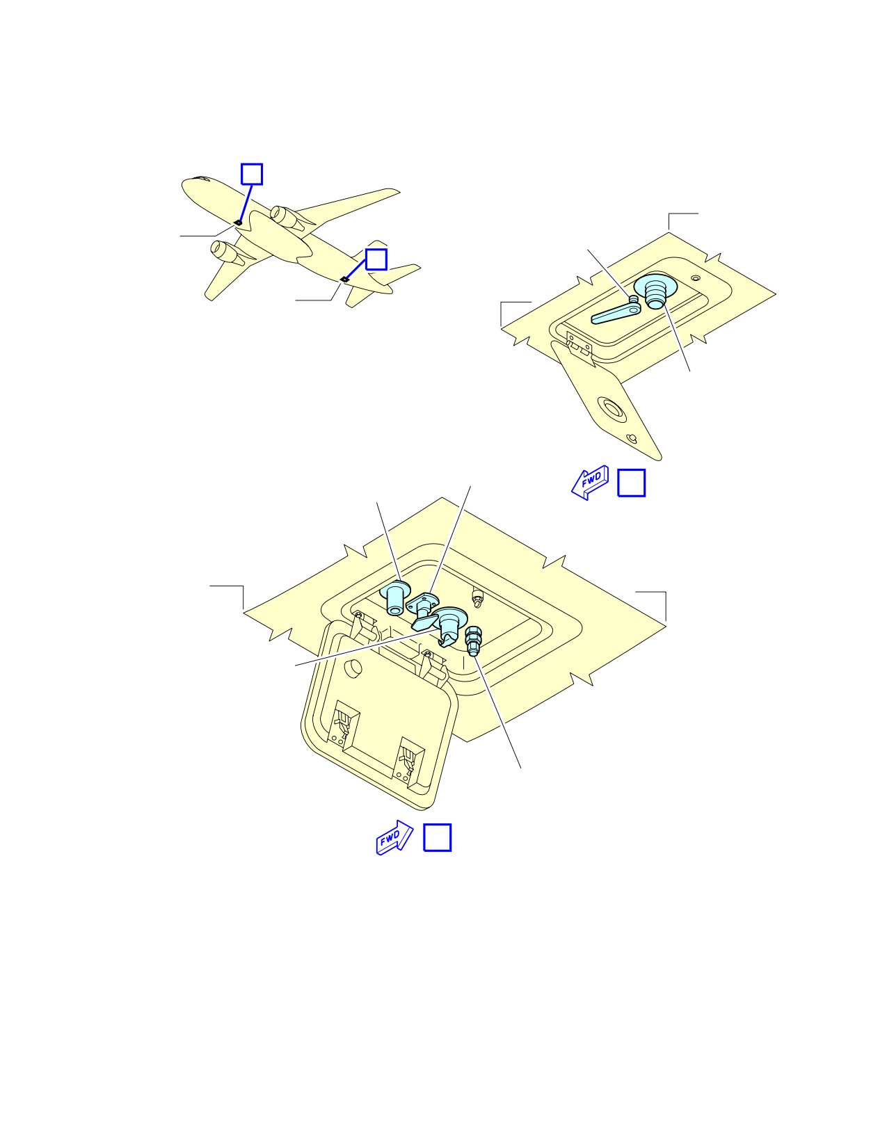
Potable Water Ground Service Panels
DISTANCE
POSITION FROM AIRCRAFT
ACCESS
MEAN HEIGHT
AFT OF NOSE
CENTERLINE
FROM GROUND
LH SIDE
RH SIDE
Potable-Water
25.2 m
0.3 m
2.6 m
-
Service Panel:
(82.68 ft)
(0.98 ft)
(8.53 ft)
Access Door 171AL
Potable-Water
11.4 m
0.15 m
1.75 m
-
Drain Panel:
(37.4 ft)
(0.49 ft)
(5.74 ft)
Access Door 133AL
NOTE : Distances are approximate.
2.
Technical Specifications
A. Connectors:
(1) On the potable-water service panel (Access Door 171AL)
-
Fill/Drain Nipple 3/4 in. (ISO 17775).
-
One ground air-pressure connector.
(2) On the potable-water drain panel (Access Door 133AL)
-
Drain Nipple 3/4 in. (ISO 17775).
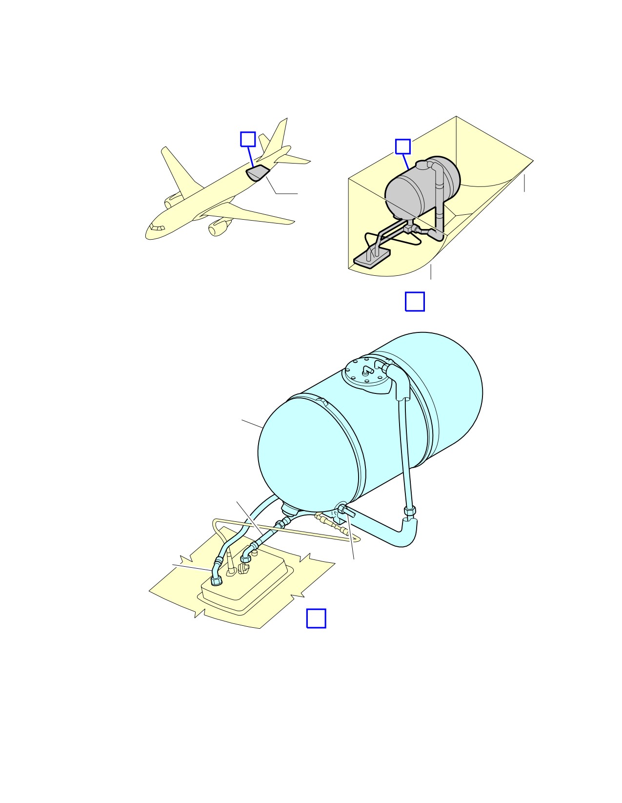
B. Usable capacity:
-
Standard configuration - one tank: 200 l (53 US gal).
C. Filling pressure:
-
3.45 bar (50 psi).
D. Typical flow rate:
-
50 l/min (13 US gal/min).
Page 1
May 01/16
5-4-9
@A318
AIRCRAFT CHARACTERISTICS - AIRPORT AND MAINTENANCE PLANNING
**ON A/C A318-100
A
FR29
133AL
DRAIN CONTROL
HANDLE
B
171AL
FR28
DRAIN PORT
FILL/DRAIN
CONTROL HANDLE
A
OVERFLOW PORT
POTABLE−WATER DRAIN PANEL
FR66
FR65
FILL/DRAIN PORT
GROUND AIR−PRESSURE
CONNECTION
B
POTABLE−WATER SERVICE PANEL
N_AC_050409_1_0290101_01_00
Ground Service Connections
Potable Water Ground Service Panels
FIGURE-5-4-9-991-029-A01
Page 2
May 01/16
5-4-9
@A318
AIRCRAFT CHARACTERISTICS - AIRPORT AND MAINTENANCE PLANNING
**ON A/C A318-100
A
B
Z170
FR68
FR65
A
POTABLE WATER
TANK
FILL/DRAIN
LINE
OVERFLOW
POTABLE WATER
LINE
DISTRIBUTION LINE
B
N_AC_050409_1_0300101_01_00
Ground Service Connections
Potable Water Tank Location
FIGURE-5-4-9-991-030-A01
Page 3
May 01/16
5-4-9

@A318
AIRCRAFT CHARACTERISTICS - AIRPORT AND MAINTENANCE PLANNING
5-4-10
Waste Water System
**ON A/C A318-100
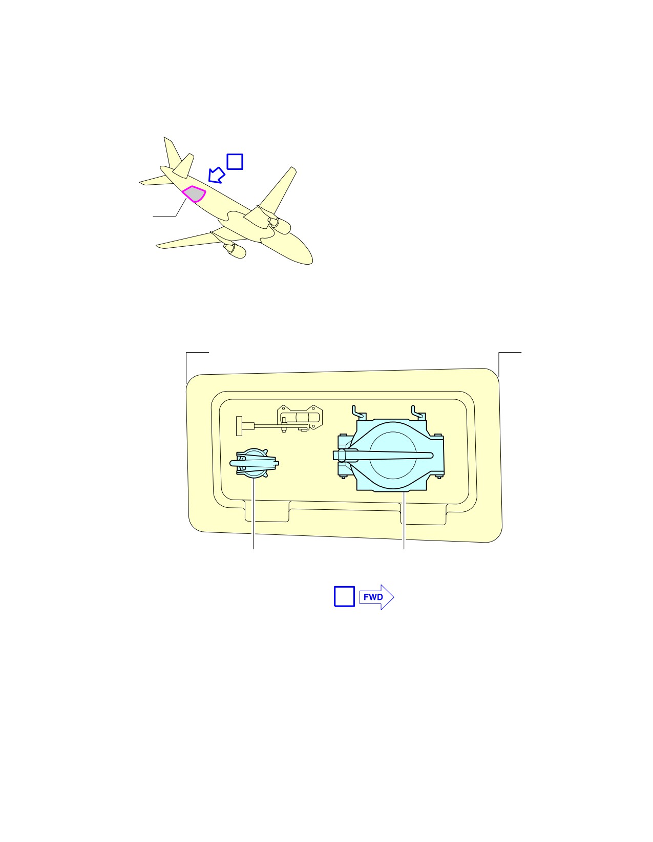
Vacuum Toilet System
1.
Vacuum Toilet System
DISTANCE
POSITION FROM AIRCRAFT
ACCESS
MEAN HEIGHT
AFT OF NOSE
CENTERLINE
FROM GROUND
LH SIDE
RH SIDE
Waste-Water
Ground Service
25.2 m
0.8 m
2.8 m
-
Panel:
(82.67 ft)
(2.62 ft)
(9.19 ft)
Access door 172AR
NOTE : Distances are approximate.
2.
Technical Specifications
A. Connectors:
-
Draining: 4 in. (ISO 17775).
-
Flushing and filling: 1 in. (ISO 17775).
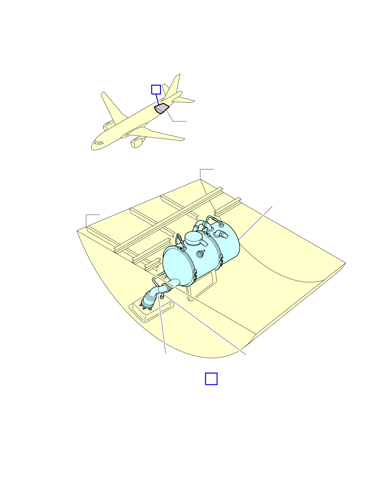
B. Usable waste tank capacity:
-
Standard configuration - one tank: 177 l (47 US gal).
C. Waste tank - Rinsing:
-
Operating pressure: 3.45 bar (50 psi).
D. Waste tank - Precharge:
-
10 l (3 US gal).
Page 1
May 01/16
5-4-10
@A318
AIRCRAFT CHARACTERISTICS - AIRPORT AND MAINTENANCE PLANNING
**ON A/C A318-100
A
Z172
FR66
FR65
FILL AND RINSE
TOILET DRAIN
CONNECTION
CONNECTION
A
N_AC_050410_1_0010101_01_00
Ground Service Connections
Waste Water Ground Service Panel
FIGURE-5-4-10-991-001-A01
Page 2
May 01/16
5-4-10
@A318
AIRCRAFT CHARACTERISTICS - AIRPORT AND MAINTENANCE PLANNING
**ON A/C A318-100
A
Z170
FR68
WASTE TANK
FR65
FLUSH LINE
DRAIN LINE
A
N_AC_050410_1_0040101_01_00
Ground Service Connections
Waste Tank Location
FIGURE-5-4-10-991-004-A01
Page 3
May 01/16
5-4-10
@A318
AIRCRAFT CHARACTERISTICS - AIRPORT AND MAINTENANCE PLANNING
5-5-0
Engine Starting Pneumatic Requirements
**ON A/C A318-100
Engine Starting Pneumatic Requirements
1.
The purpose of this section is to provide the minimum air data requirements at the aircraft
connection, needed to start the engine within no more than 60 seconds, at sea level (0 feet), for a set
of Outside Air Temperatures (OAT).
ABBREVIATION
DEFINITION
A/C
Aircraft
ASU
Air Start Unit
HPGC
High Pressure Ground Connection
OAT
Outside Air Temperature
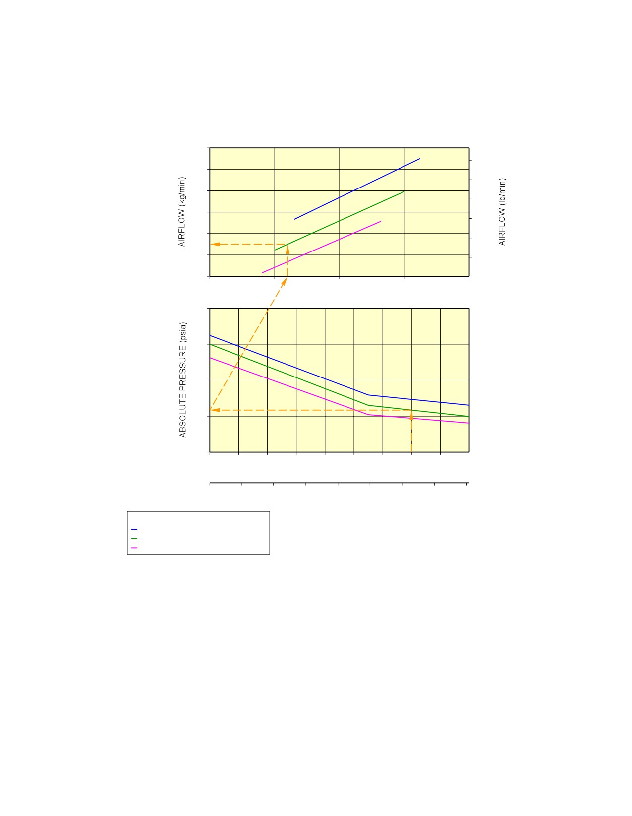
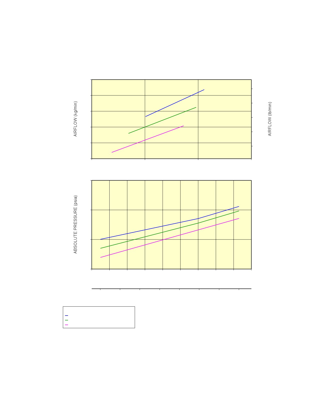
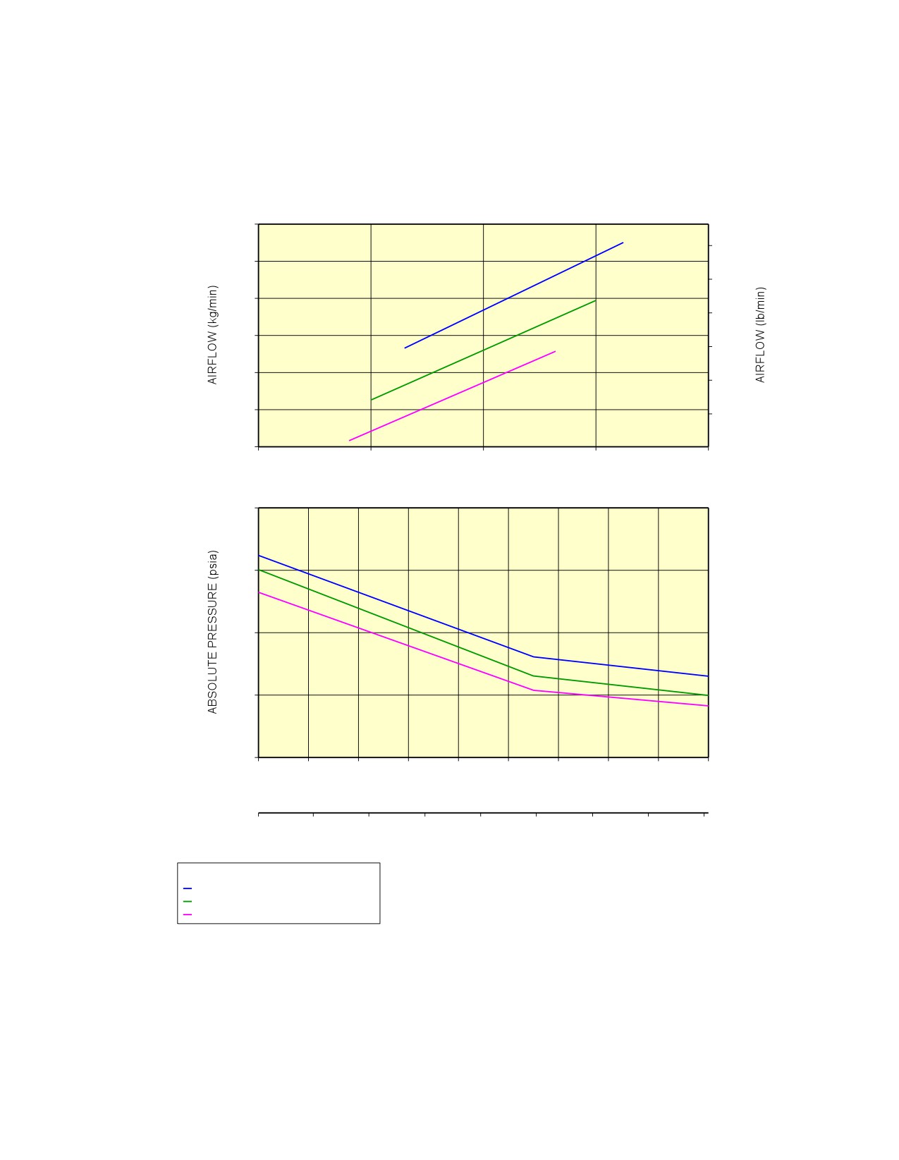
A. Air data (discharge temperature, absolute discharge pressure) are given at the HPGC.
B. For a given OAT the following charts are used to determine an acceptable combination for air
discharge temperature, absolute discharge pressure and mass flow rate.
C. This section addresses requirements for the ASU only, and is not representative of the start
performance of the aircraft using the APU or engine cross bleed procedure.
D. To protect the A/C, the charts feature, if necessary:
-
The maximum discharge pressure at the HPGC
-
The maximum discharge temperature at the HPGC.
Page 1
May 01/16
5-5-0
@A318
AIRCRAFT CHARACTERISTICS - AIRPORT AND MAINTENANCE PLANNING
**ON A/C A318-100
CFM56 SERIES/SEA LEVEL
STARTING TIME: LESS THAN 60 s
AIR DATA AT AIRCRAFT CONNECTION
80
170
75
160
70
150
65
140
60
130
55
120
50
35
40
45
50
55
ABSOLUTE PRESSURE (psia)
55
50
45
40
35
−40
−30
−20
−10
0
10
20
30
40
50
OUTSIDE AIR TEMPERATURE OAT (° C)
−40
−20
0
20
40
60
80
100
120
OUTSIDE AIR TEMPERATURE OAT (° F)
ASU DISCHARGE TEMPERATURE:
100° C (212° F)
150° C (302° F)
220° C (428° F) MAX.
EXAMPLE:
FOR AN OAT OF 30° C (86° F) AND AN ASU PROVIDING A DISCHARGE TEMPERATURE OF 150° C (302° F)
AT HPGC:
− THE REQUIRED PRESSURE AT HPGC IS 41 psia
− THE REQUIRED AIRFLOW AT A/C CONNECTION IS 57.5 kg/min.
NOTE:
IN CASE THE ACTUAL DISCHARGE TEMPERATURE OF THE ASU DIFFERS SUBSTANTIALLY FROM THE
ONES GIVEN IN THE CHARTS, A SIMPLE INTERPOLATION (LINEAR) IS SUFFICIENT TO DETERMINE THE
REQUIRED AIR DATA.
N_AC_050500_1_0050101_01_00
Example for Use of the Charts
FIGURE-5-5-0-991-005-A01
Page 2
May 01/16
5-5-0
@A318
AIRCRAFT CHARACTERISTICS - AIRPORT AND MAINTENANCE PLANNING
**ON A/C A318-100
PW 6000 SERIES/SEA LEVEL
STARTING TIME: LESS THAN 60 s
AIR DATA AT AIRCRAFT CONNECTION
80
170
75
160
70
150
65
140
60
130
55
40
45
50
55
ABSOLUTE PRESSURE (psia)
55
50
45
40
−45
−35
−25
−15
−5
5
15
25
35
45
OUTSIDE AIR TEMPERATURE OAT (° C)
−40
−20
0
20
40
60
80
100
OUTSIDE AIR TEMPERATURE OAT (° F)
ASU DISCHARGE TEMPERATURE:
100° C (212° F)
150° C (302° F)
220° C (428° F) MAX.
N_AC_050500_1_0060101_01_00
Engine Starting Pneumatic Requirements
PW 6000 Series Engine
FIGURE-5-5-0-991-006-A01
Page 3
May 01/16
5-5-0
@A318
AIRCRAFT CHARACTERISTICS - AIRPORT AND MAINTENANCE PLANNING
**ON A/C A318-100
CFM56 SERIES/SEA LEVEL
STARTING TIME: LESS THAN 60 s
AIR DATA AT AIRCRAFT CONNECTION
80
170
75
160
70
150
65
140
60
130
55
120
50
35
40
45
50
55
ABSOLUTE PRESSURE (psia)
55
50
45
40
35
−40
−30
−20
−10
0
10
20
30
40
50
OUTSIDE AIR TEMPERATURE OAT (° C)
−40
−20
0
20
40
60
80
100
120
OUTSIDE AIR TEMPERATURE OAT (° F)
ASU DISCHARGE TEMPERATURE:
100° C (212° F)
150° C (302° F)
220° C (428° F) MAX.
N_AC_050500_1_0070101_01_00
Engine Starting Pneumatic Requirements
CFM56 Series Engine
FIGURE-5-5-0-991-007-A01
Page 4
May 01/16
5-5-0

@A318
AIRCRAFT CHARACTERISTICS - AIRPORT AND MAINTENANCE PLANNING
5-6-0
Ground Pneumatic Power Requirements
**ON A/C A318-100
Ground Pneumatic Power Requirements
1.
General
This section describes the required performance for the ground equipment to maintain the cabin
temperature at 27 ˚C (80.6 ˚F) for the cooling or 21 ˚C (69.8 ˚F) for heating cases after boarding
(Section 5.7 - steady state), and provides the time needed to cool down or heat up the aircraft cabin
to the required temperature (Section 5.6 - dynamic cases with aircraft empty).
ABBREVIATION
DEFINITION
A/C
Aircraft
AHM
Aircraft Handling Manual
AMM
Aircraft Maintenance Manual
GC
Ground Connection
GSE
Ground Service Equipment
IFE
In-Flight Entertainment
OAT
Outside Air Temperature
PCA
Pre-Conditioned Air
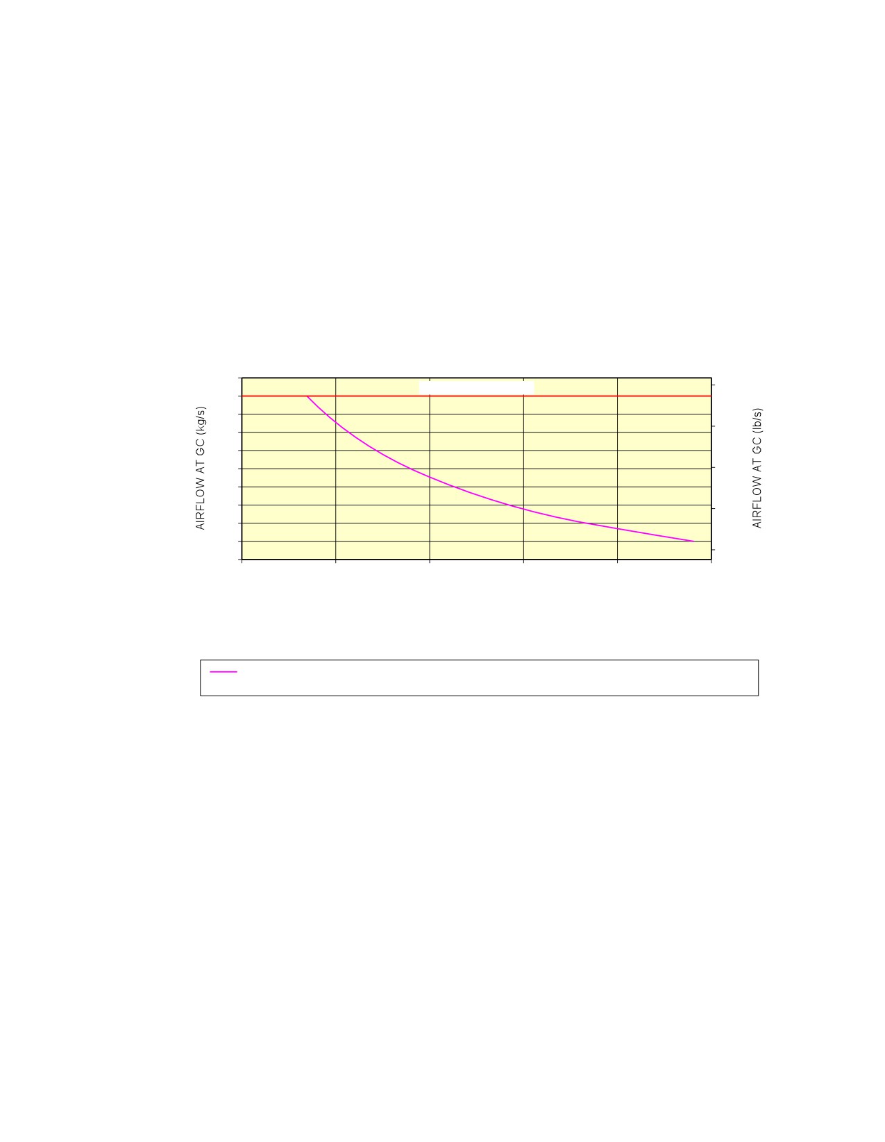
A. The air flow rates and temperature requirements for the GSE, provided in Sections 5.6 and 5.7,
are given at A/C ground connection.
NOTE : The cooling capacity of the equipment (kW) is only indicative and is not sufficient by
itself to ensure the performance (outlet temperature and flow rate combinations are
the requirements needed for ground power). An example of cooling capacity
calculation is given in Section 5.7.
NOTE : The maximum air flow is driven by pressure limitation at the ground connection.
B. For temperatures at ground connection below 2 ˚C (35.6 ˚F) (Subfreezing), the ground
equipment shall be compliant with the Airbus document ”Subfreezing PCA Carts - Compliance
Document for Suppliers” (contact Airbus to obtain this document) defining all the requirements
with which Subfreezing Pre-Conditioning Air equipment must comply to allow its use on Airbus
aircraft. These requirements are in addition to the functional specifications included in the IATA
AHM997.
2.
Ground Pneumatic Power Requirements
This section provides the ground pneumatic power requirements for:
-
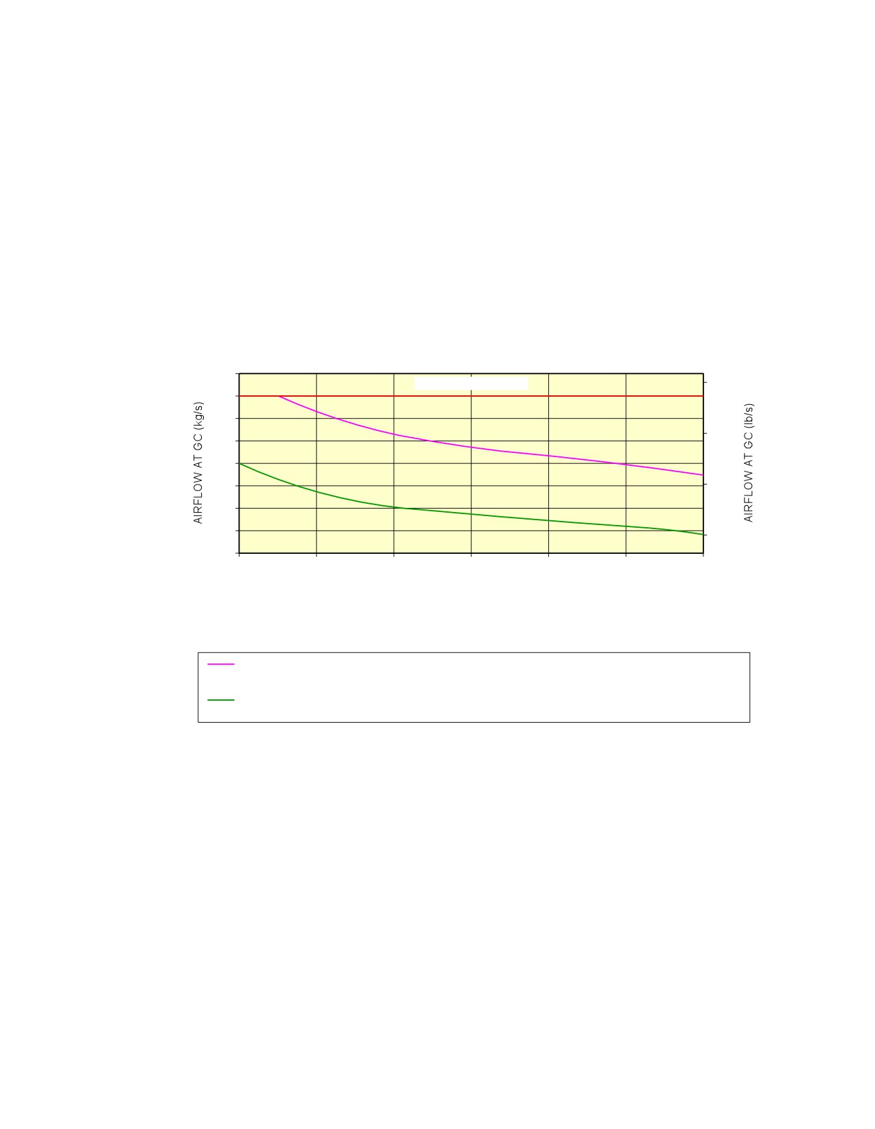
Heating (pull up) the cabin, initially at OAT, up to 21 ˚C (69.8 ˚F) (see FIGURE
5-6-0-991-001-A)
-
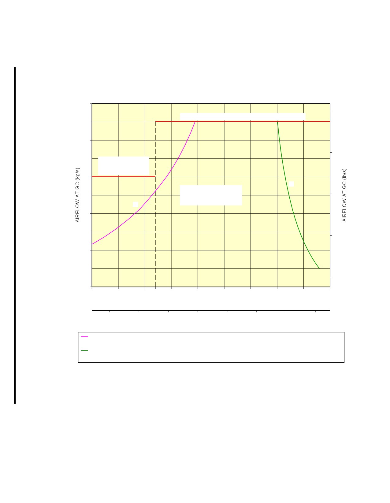
Cooling (pull down) the cabin, initially at OAT, down to 27 ˚C (80.6 ˚F) (see FIGURE
5-6-0-991-002-A).
Page 1
May 01/16
5-6-0
@A318
AIRCRAFT CHARACTERISTICS - AIRPORT AND MAINTENANCE PLANNING
**ON A/C A318-100
PULL UP PERFORMANCE
1.4
MAXIMUM AIRFLOW
3.0
1.3
1.2
2.5
1.1
1.0
0.9
2.0
0.8
0.7
1.5
0.6
0.5
1.0
0.4
15
30
45
60
75
90
TIME TO HEAT CABIN TO +21° C (+69.8° F) ON GROUND (min)
OAT ISA −38° C ( −36.4° F); GC INLET +70° C (+158° F); EMPTY CABIN; IFE OFF; NO SOLAR
LOAD; LIGHTS ON; GALLEYS OFF; RECIRCULATION FANS ON
N_AC_050600_1_0010101_01_00
Ground Pneumatic Power Requirements
Heating
FIGURE-5-6-0-991-001-A01
Page 2
May 01/16
5-6-0
@A318
AIRCRAFT CHARACTERISTICS - AIRPORT AND MAINTENANCE PLANNING
**ON A/C A318-100
PULL DOWN PERFORMANCE
1.4
MAXIMUM AIRFLOW
3.0
1.3
1.2
2.5
1.1
1.0
0.9
2.0
0.8
0.7
1.5
0.6
30
45
60
75
90
105
120
TIME TO COOL CABIN TO +27° C (+80.6° F) ON GROUND (min)
OAT ISA +23° C (+73.4° F); GC INLET +2° C (+35.6° F); EMPTY CABIN; IFE OFF; NO SOLAR
LOAD; LIGHTS ON; GALLEYS OFF; RECIRCULATION FANS ON
OAT ISA +23° C (+73.4° F); GC INLET −10° C (+14° F); EMPTY CABIN; IFE OFF; NO SOLAR
LOAD; LIGHTS ON; GALLEYS OFF; RECIRCULATION FANS ON
N_AC_050600_1_0020101_01_00
Ground Pneumatic Power Requirements
Cooling
FIGURE-5-6-0-991-002-A01
Page 3
May 01/16
5-6-0
@A318
AIRCRAFT CHARACTERISTICS - AIRPORT AND MAINTENANCE PLANNING
5-7-0
Preconditioned Airflow Requirements
**ON A/C A318-100
Preconditioned Airflow Requirements
1.
This section provides the preconditioned airflow rate and temperature needed to maintain the cabin
temperature at 27 ˚C (80.6 ˚F) for the cooling or 21 ˚C (69.8 ˚F) for the heating cases.
These settings are not intended to be used for operation (they are not a substitute for the settings
given in the AMM). They are based on theoretical simulations and give the picture of a real steady
state.
The purpose of the air conditioning (cooling) operation (described in the AMM) is to maintain the
cabin temperature below 27 ˚C (80.6 ˚F) during boarding (therefore it is not a steady state).
Page 1
May 01/16
5-7-0
@A318
AIRCRAFT CHARACTERISTICS - AIRPORT AND MAINTENANCE PLANNING
**ON A/C A318-100
COOLING/HEATING PERFORMANCE
1.4
3.0
MAXIMUM AIRFLOW (RECIRCULATION FANS OFF)
1.2
2.5
MAXIMUM AIRFLOW
(RECIRCULATION
FANS ON)
1.0
H
SETTINGS NOT
INTENDED TO BE USED
2.0
FOR OPERATION
C
0.8
1.5
0.6
1.0
0.4
−10
−5
0
2
5
10
15
20
25
30
35
INLET TEMPERATURE AT GC (° C)
20
30
40
50
60
70
80
90
INLET TEMPERATURE AT GC (° F)
OAT ISA +23° C (73.4° F); EMPTY CABIN; IFE ON; LIGHTS ON; SOLAR LOAD; RECIRCULATION
FANS ON; GALLEYS ON
OAT ISA −38° C ( −36.4° F); EMPTY CABIN; IFE OFF; LIGHTS ON; NO SOLAR LOAD; RECIRCULATION
FANS ON; GALLEYS OFF
N_AC_050700_1_0010101_01_04
Preconditioned Airflow Requirements
FIGURE-5-7-0-991-001-A01
Page 2
May 01/16
5-7-0
@A318
AIRCRAFT CHARACTERISTICS - AIRPORT AND MAINTENANCE PLANNING
5-8-0
Ground Towing Requirements
**ON A/C A318-100
Ground Towing Requirements
1.
This section provides information on aircraft towing.
This aircraft is designed with means for conventional or towbarless towing. Information/procedures
can be found for both in AMM 09.
Status on towbarless towing equipment qualification can be found in ISI 09.11.00001.
One towbar fitting is installed at the front of the leg.
The main landing gears have attachment points for towing or debogging (for details, refer ARM 07).
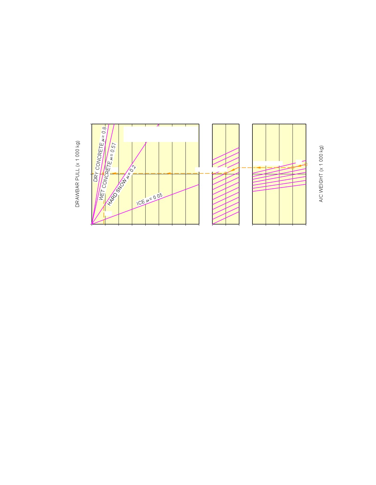
This section shows the chart to determine the drawbar pull and tow tractor mass requirements as a
function of the following physical characteristics:
-
Aircraft weight,
-
Number of engines at idle,
-
Slope.
The chart is based on the engine type with the highest idle thrust level.
2.
Towbar design guidelines
The aircraft towbar shall comply with the following standards:
-
ISO 8267-1, ”Aircraft - Towbar Attachment Fitting - Interface Requirements - Part 1: Main Line
Aircraft”,
-
SAE AS 1614, ”Main Line Aircraft Towbar Attach Fitting Interface”,
-
SAE ARP 1915, ”Aircraft Towbar”,
-
ISO 9667, ”Aircraft Ground Support Equipment - Towbar - Connection to Aircraft and Tractor”,
-
EN 12312-7, ”Aircraft Ground Support Equipment - Specific Requirements - Part 7: Aircraft
Movement Equipment”,
-
IATA Airport Handling Manual AHM 958, ”Functional Specification for an Aircraft Towbar”.
A conventional type towbar is required which should be equipped with a damping system (to protect
the nose gear against jerks) and with towing shear pins:
-
A traction shear pin calibrated at 9 425 daN (21 188 lbf),
-
A torsion pin calibrated at 826 m.daN (6 092 lbf.ft).
The towing head is designed according to ISO 8267-1, cat. I.
Page 1
May 01/16
5-8-0
@A318
AIRCRAFT CHARACTERISTICS - AIRPORT AND MAINTENANCE PLANNING
**ON A/C A318-100
10
BREAKAWAY RESISTANCE 4%
# OF ENGINES ON FOR PB: 1
ENGINE THRUST 616 daN
60
65
1.5% SLOPE
60
5.1
1 ENGINE ON
55
50
5
45
40
35
9.0
0
0
10
20
30
40
50
60
70
80
0
1
2
0
0.5
1.0
1.5
2.0
TOTAL TRACTION WHEEL LOAD (x 1 000 kg)
No. OF ENGINES
SLOPE ( % )
AT IDLE
EXAMPLE HOW TO DETERMINE THE MASS REQUIREMENT TO TOW A A318 AT 60 000 kg, AT 1.5% SLOPE,
1 ENGINE AT IDLE AND FOR WET TARMAC CONDITIONS:
− ON THE RIGHT HAND SIDE OF THE GRAPH, CHOOSE THE RELEVANT AIRCRAFT WEIGHT (60 000 kg),
− FROM THIS POINT DRAW A PARALLEL LINE TO THE REQUIRED SLOPE PERCENTAGE (1.5%),
− FROM THE POINT OBTAINED DRAW A STRAIGHT HORIZONTAL LINE UNTIL No. OF ENGINES AT IDLE = 2,
− FROM THIS POINT DRAW A PARALLEL LINE TO THE REQUESTED No. OF ENGINES (1),
− FROM THIS POINT DRAW A STRAIGHT HORIZONTAL LINE TO THE DRAWBAR PULL AXIS,
− THE Y−COORDINATE OBTAINED IS THE NECESSARY DRAWBAR PULL FOR THE TRACTOR (5 100 kg),
− SEARCH THE INTERSECTION WITH THE "WET CONCRETE" LINE.
THE OBTAINED X−COORDINATE IS THE RECOMMENDED MINIMUM TRACTOR WEIGHT (9 000 kg).
N_AC_050800_1_0010101_01_05
Ground Towing Requirements
FIGURE-5-8-0-991-001-A01
Page 2
May 01/16
5-8-0
@A318
AIRCRAFT CHARACTERISTICS - AIRPORT AND MAINTENANCE PLANNING
5-9-0
De-Icing and External Cleaning
**ON A/C A318-100
De-Icing and External Cleaning
1.
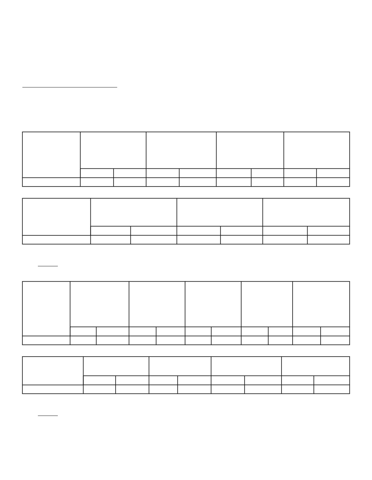
De-Icing and External Cleaning on Ground
The mobile equipment for aircraft de-icing and external cleaning must be capable of reaching heights
up to approximately 13 m (43 ft).
2.
De-Icing
Wingtip Devices
Wing Top Surface
(Both Inside and
HTP Top Surface
VTP
AIRCRAFT
(Both Sides)
Outside Surfaces)
(Both Sides)
(Both Sides)
TYPE
(Both Sides)
m2
ft2
m2
ft2
m2
ft2
m2
ft2
A318
100
1 076
2
22
27
291
46
495
Nacelle and Pylon
Fuselage Top Surface
(Top Third - 120˚ Arc)
Total De-Iced Area
AIRCRAFT TYPE
(Top Third - 120˚ Arc)
(All Engines)
m2
ft2
m2
ft2
m2
ft2
A318
112
1 206
24
258
310
3 337
NOTE : Dimensions are approximate.
3.
External Cleaning
Wing Lower
Wingtip Devices
Wing Top
Surface
(Both Inside and
HTP Top
HTP Lower
AIRCRAFT
Surface
(Including Flap
Outside
Surface
Surface
TYPE
(Both Sides)
Track Fairing)
Surfaces)
(Both Sides)
(Both Sides)
(Both Sides)
(Both Sides)
m2
ft2
m2
ft2
m2
ft2
m2
ft2
m2
ft2
A318
100
1 076
103
1 109
2
22
27
291
27
291
VTP
Fuselage and
Nacelle and Pylon
Total Cleaned Area
AIRCRAFT TYPE
(Both Sides)
Belly Fairing
(All Engines)
m2
ft2
m2
ft2
m2
ft2
m2
ft2
A318
46
495
343
3 692
73
786
723
7 782
NOTE : Dimensions are approximate.
Page 1
May 01/16
5-9-0
@A318
AIRCRAFT CHARACTERISTICS - AIRPORT AND MAINTENANCE PLANNING
OPERATING CONDITIONS
6-1-0
Engine Exhaust Velocities and Temperatures
**ON A/C A318-100
Engine Exhaust Velocities and Temperatures
1.
General
This section provides the estimated engine exhaust efflux velocities and temperatures contours for
Ground Idle, Breakaway and Maximum Take-Off (MTO) conditions.
Page 1
May 01/16
6-1-0
@A318
AIRCRAFT CHARACTERISTICS - AIRPORT AND MAINTENANCE PLANNING
6-1-1
Engine Exhaust Velocities Contours - Ground Idle Power
**ON A/C A318-100
Engine Exhaust Velocities Contours - Ground Idle Power
1.
This section provides engine exhaust velocities contours at ground idle power.
Page 1
May 01/16
6-1-1
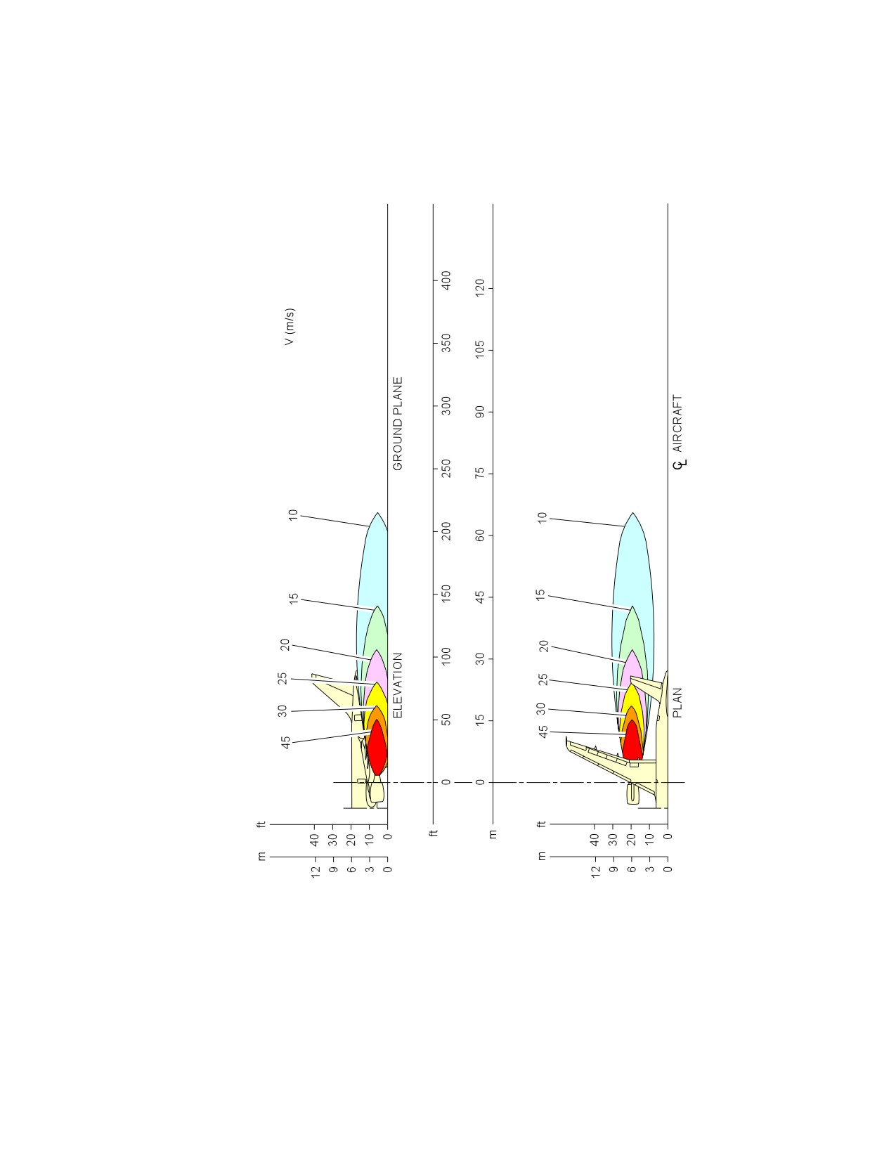
@A318
AIRCRAFT CHARACTERISTICS - AIRPORT AND MAINTENANCE PLANNING
**ON A/C A318-100
N_AC_060101_1_0010101_01_01
Engine Exhaust Velocities
Ground Idle Power -- CFM56 Series Engine
FIGURE-6-1-1-991-001-A01
Page 2
May 01/16
6-1-1
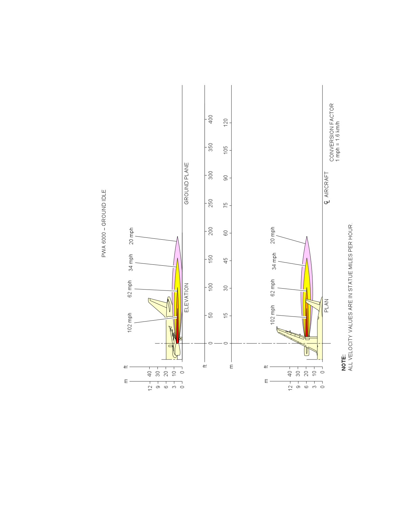
@A318
AIRCRAFT CHARACTERISTICS - AIRPORT AND MAINTENANCE PLANNING
**ON A/C A318-100
N_AC_060101_1_0020101_01_01
Engine Exhaust Velocities
Ground Idle Power -- PW 6000 Series Engine
FIGURE-6-1-1-991-002-A01
Page 3
May 01/16
6-1-1
@A318
AIRCRAFT CHARACTERISTICS - AIRPORT AND MAINTENANCE PLANNING
6-1-2
Engine Exhaust Temperatures Contours - Ground Idle Power
**ON A/C A318-100
Engine Exhaust Temperatures Contours - Ground Idle Power
1.
This section provides engine exhaust temperatures contours at ground idle power.
Page 1
May 01/16
6-1-2
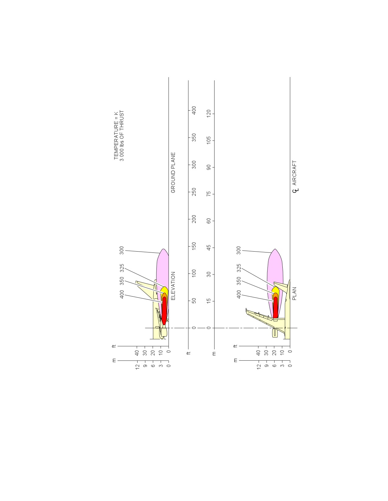
@A318
AIRCRAFT CHARACTERISTICS - AIRPORT AND MAINTENANCE PLANNING
**ON A/C A318-100
N_AC_060102_1_0010101_01_01
Engine Exhaust Temperatures
Ground Idle Power -- CFM56 Series Engine
FIGURE-6-1-2-991-001-A01
Page 2
May 01/16
6-1-2

@A318
AIRCRAFT CHARACTERISTICS - AIRPORT AND MAINTENANCE PLANNING
**ON A/C A318-100
N_AC_060102_1_0020101_01_01
Engine Exhaust Temperatures
Ground Idle Power -- PW 6000 Series Engine
FIGURE-6-1-2-991-002-A01
Page 3
May 01/16
6-1-2
@A318
AIRCRAFT CHARACTERISTICS - AIRPORT AND MAINTENANCE PLANNING
6-1-3
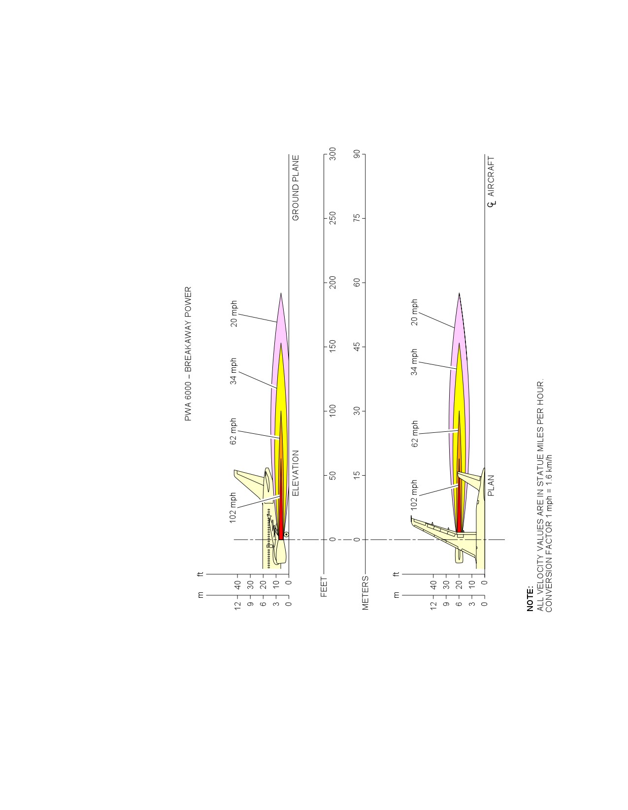
Engine Exhaust Velocities Contours - Breakaway Power
**ON A/C A318-100
Engine Exhaust Velocities Contours - Breakaway Power
1.
This section provides engine exhaust velocities contours at breakaway power.
Page 1
May 01/16
6-1-3
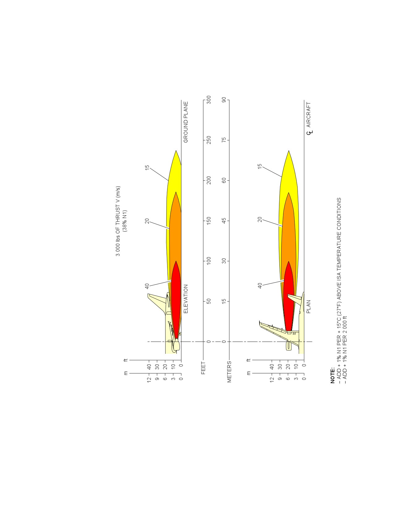
@A318
AIRCRAFT CHARACTERISTICS - AIRPORT AND MAINTENANCE PLANNING
**ON A/C A318-100
N_AC_060103_1_0010101_01_01
Engine Exhaust Velocities
Breakaway Power -- CFM56 Series Engine
FIGURE-6-1-3-991-001-A01
Page 2
May 01/16
6-1-3
@A318
AIRCRAFT CHARACTERISTICS - AIRPORT AND MAINTENANCE PLANNING
**ON A/C A318-100
N_AC_060103_1_0020101_01_01
Engine Exhaust Velocities
Breakaway Power -- PW 6000 Series Engine
FIGURE-6-1-3-991-002-A01
Page 3
May 01/16
6-1-3
@A318
AIRCRAFT CHARACTERISTICS - AIRPORT AND MAINTENANCE PLANNING
6-1-4
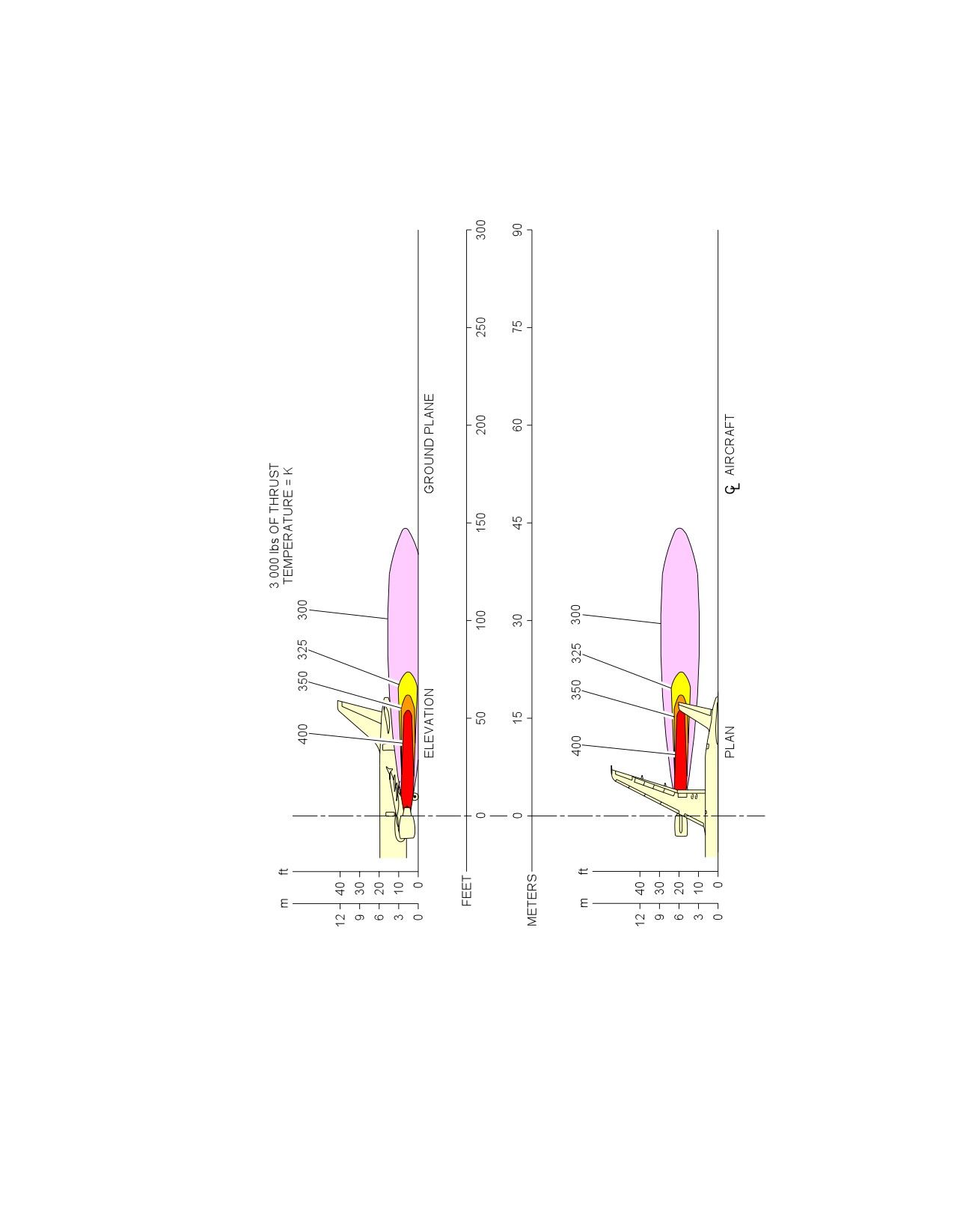
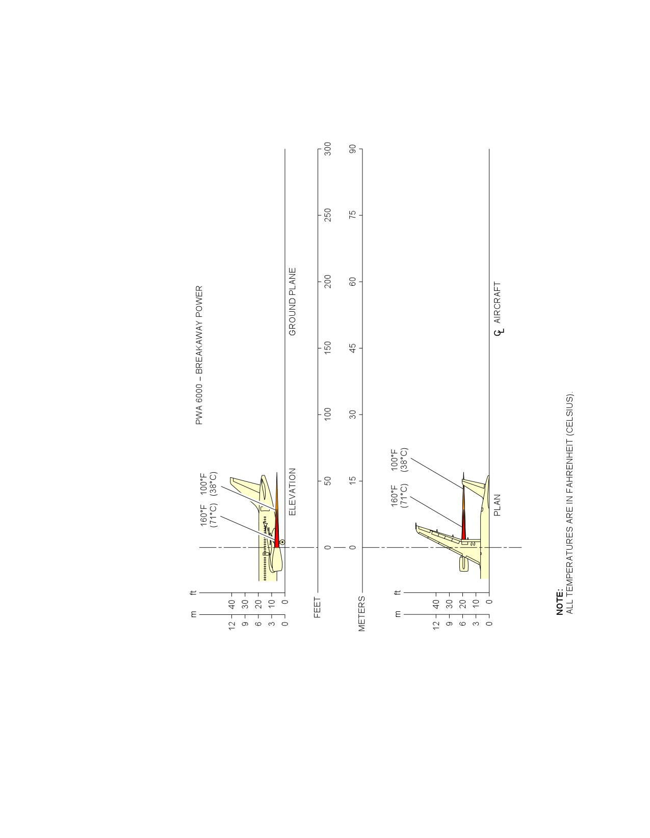
Engine Exhaust Temperatures Contours - Breakaway Power
**ON A/C A318-100
Engine Exhaust Temperatures Contours - Breakaway Power
1.
This section provides engine exhaust temperatures contours at breakaway power.
Page 1
May 01/16
6-1-4
@A318
AIRCRAFT CHARACTERISTICS - AIRPORT AND MAINTENANCE PLANNING
**ON A/C A318-100
N_AC_060104_1_0010101_01_01
Engine Exhaust Temperatures
Breakaway Power -- CFM56 Series Engine
FIGURE-6-1-4-991-001-A01
Page 2
May 01/16
6-1-4
@A318
AIRCRAFT CHARACTERISTICS - AIRPORT AND MAINTENANCE PLANNING
**ON A/C A318-100
N_AC_060104_1_0020101_01_01
Engine Exhaust Temperatures
Breakaway Power -- PW 6000 Series Engine
FIGURE-6-1-4-991-002-A01
Page 3
May 01/16
6-1-4
@A318
AIRCRAFT CHARACTERISTICS - AIRPORT AND MAINTENANCE PLANNING
6-1-5
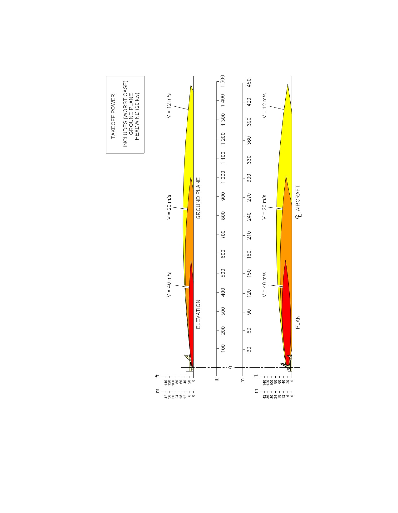
Engine Exhaust Velocities Contours - Takeoff Power
**ON A/C A318-100
Engine Exhaust Velocities Contours - Takeoff Power
1.
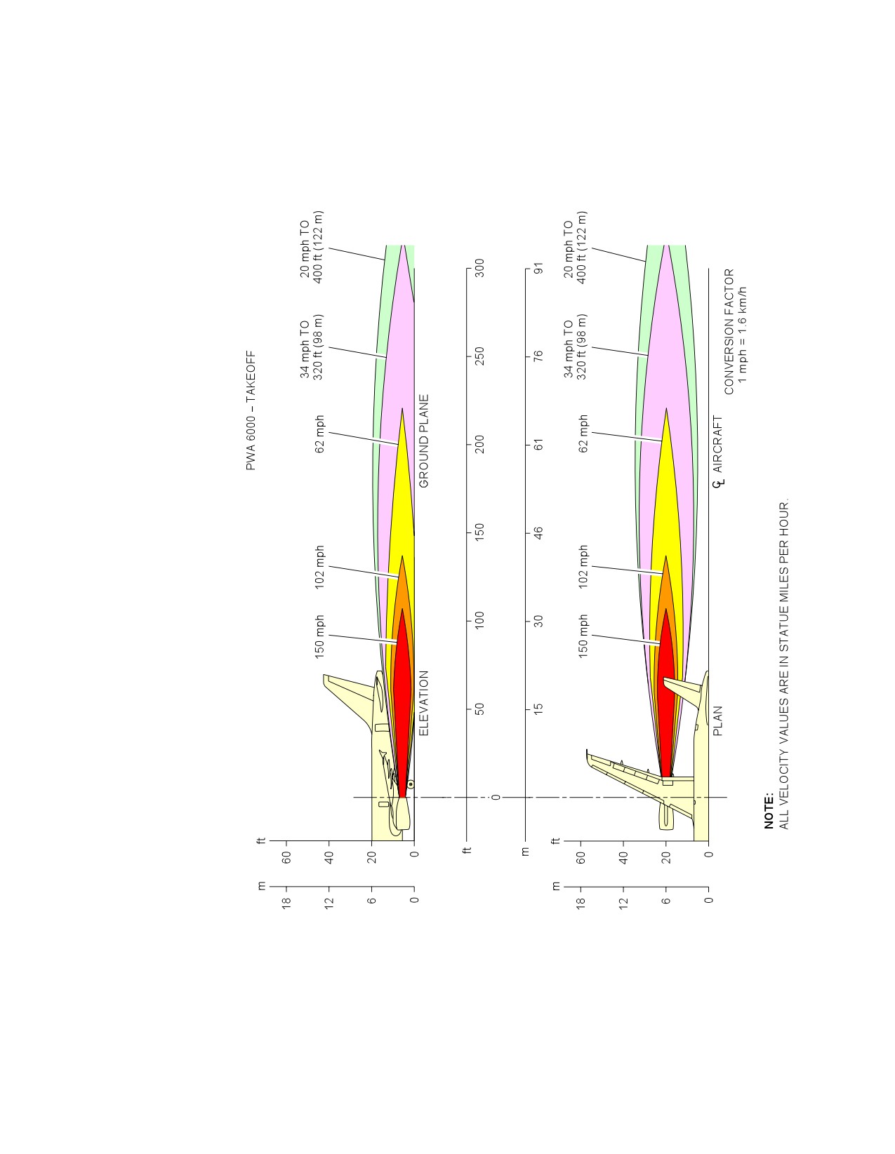
This section provides engine exhaust velocities contours at takeoff power.
Page 1
May 01/16
6-1-5
@A318
AIRCRAFT CHARACTERISTICS - AIRPORT AND MAINTENANCE PLANNING
**ON A/C A318-100
N_AC_060105_1_0010101_01_01
Engine Exhaust Velocities
Takeoff Power -- CFM56 Series Engine
FIGURE-6-1-5-991-001-A01
Page 2
May 01/16
6-1-5
@A318
AIRCRAFT CHARACTERISTICS - AIRPORT AND MAINTENANCE PLANNING
**ON A/C A318-100
N_AC_060105_1_0020101_01_01
Engine Exhaust Velocities
Takeoff Power -- PW 6000 Series Engine
FIGURE-6-1-5-991-002-A01
Page 3
May 01/16
6-1-5
@A318
AIRCRAFT CHARACTERISTICS - AIRPORT AND MAINTENANCE PLANNING
6-1-6
Engine Exhaust Temperatures Contours - Takeoff Power
**ON A/C A318-100
Engine Exhaust Temperatures Contours - Takeoff Power
1.
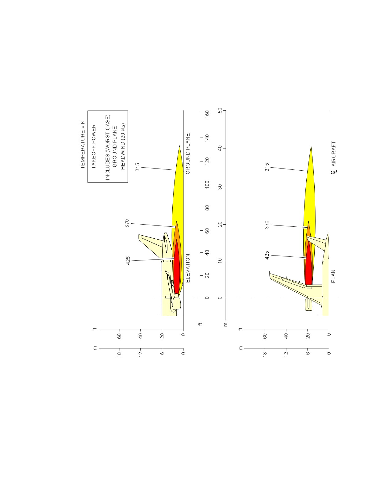
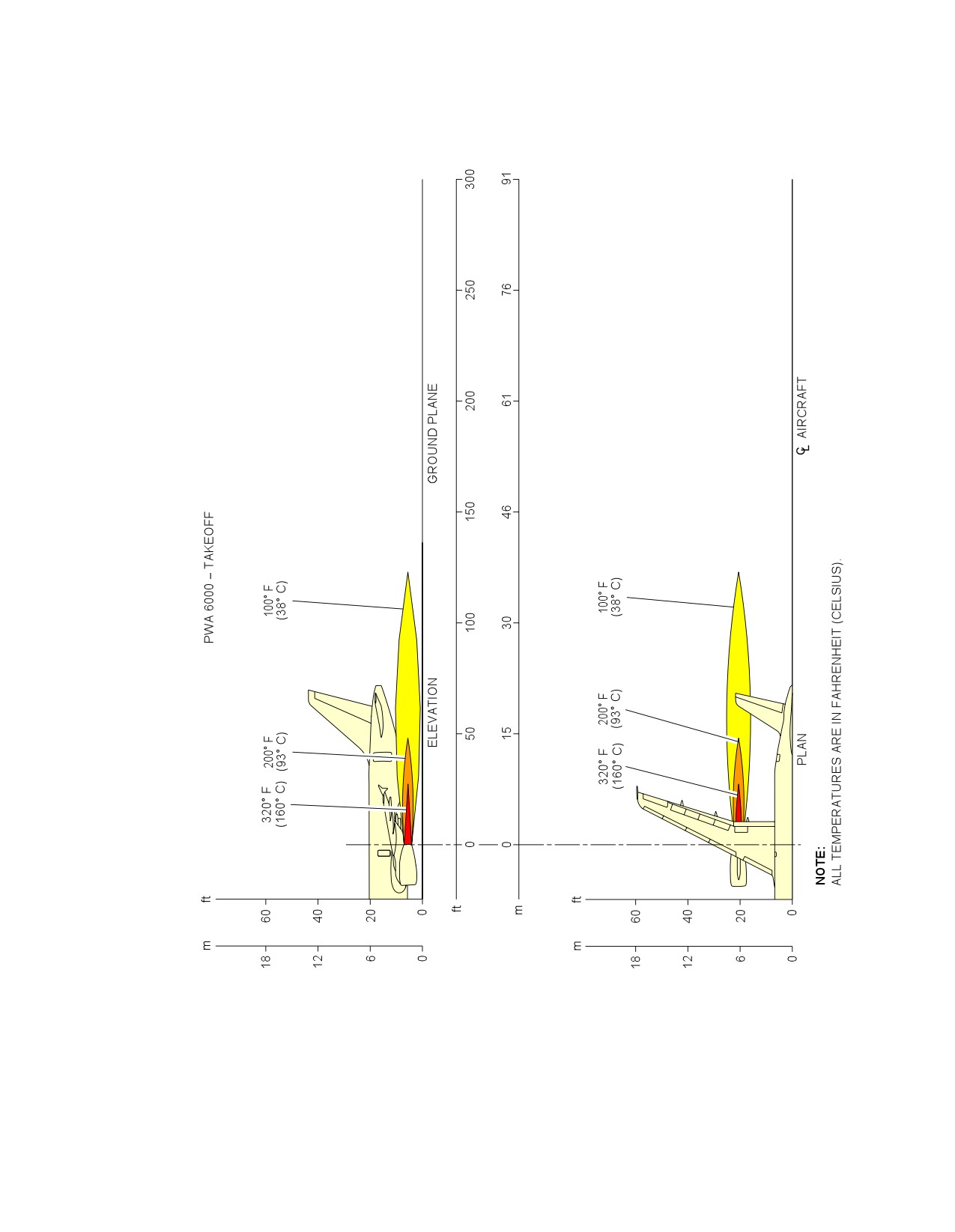
This section provides engine exhaust temperatures contours at takeoff power.
Page 1
May 01/16
6-1-6
@A318
AIRCRAFT CHARACTERISTICS - AIRPORT AND MAINTENANCE PLANNING
**ON A/C A318-100
N_AC_060106_1_0010101_01_01
Engine Exhaust Temperatures
Takeoff Power -- CFM56 Series Engine
FIGURE-6-1-6-991-001-A01
Page 2
May 01/16
6-1-6
@A318
AIRCRAFT CHARACTERISTICS - AIRPORT AND MAINTENANCE PLANNING
**ON A/C A318-100
N_AC_060106_1_0020101_01_01
Engine Exhaust Temperatures
Takeoff Power -- PW 6000 Series Engine
FIGURE-6-1-6-991-002-A01
Page 3
May 01/16
6-1-6
@A318
AIRCRAFT CHARACTERISTICS - AIRPORT AND MAINTENANCE PLANNING
6-3-0
Danger Areas of Engines
**ON A/C A318-100
Danger Areas of Engines
1.
Danger Areas of the Engines.
Page 1
May 01/16
6-3-0
@A318
AIRCRAFT CHARACTERISTICS - AIRPORT AND MAINTENANCE PLANNING
6-3-1
Ground Idle Power
**ON A/C A318-100
Ground Idle Power
1.
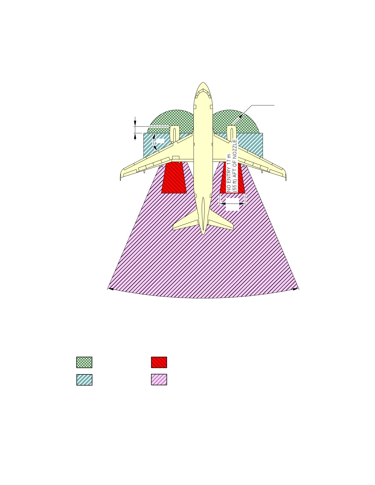
This section provides danger areas of the engines at ground idle power conditions.
Page 1
May 01/16
6-3-1
@A318
AIRCRAFT CHARACTERISTICS - AIRPORT AND MAINTENANCE PLANNING
**ON A/C A318-100
R = 4.6 m
1.5 m
(15 ft)
(5 ft)
45°
6.1 m
(20 ft)
30°
TO 55 m (180 ft) INCLUDES CROSS WIND EFFECT
NOTE:
INLET SUCTION
EXHAUST WAKE DANGER AREA
DANGER AREA
65 mph (105 km/h) OR GREATER
EXHAUST WAKE DANGER AREA
ENTRY CORRIDOR
65 mph (105 km/h) OR LESS
N_AC_060301_1_0010101_01_02
Danger Areas of the Engines
CFM56 Series Engine
FIGURE-6-3-1-991-001-A01
Page 2
May 01/16
6-3-1
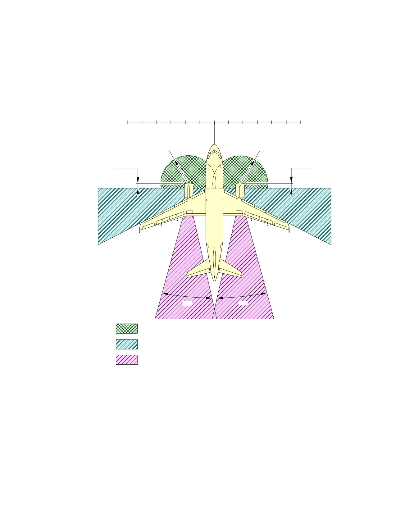
@A318
AIRCRAFT CHARACTERISTICS - AIRPORT AND MAINTENANCE PLANNING
**ON A/C A318-100
FEET
(METERS)
60
50
40
30
20
10
10
20
30
40
50
60
(18)
(15)
(12)
(9)
(6)
(3)
0
(3)
(6)
(9)
(12)
(15)
(18)
R = 9 ft
R = 9 ft
(2.74 m)
(2.74 m)
3.3 ft
3.3 ft
(1 m)
(1 m)
30°
30°
INTAKE SUCTION DANGER AREA
ENTRY CORRIDOR
EXHAUST DANGER AREA (AFT OF EXHAUST NOZZLE):
200 ft (61 m) − GROUND IDLE (20 kt HEADWIND)
N_AC_060301_1_0020101_01_01
Danger Areas of the Engines
PW 6000 Series Engine
FIGURE-6-3-1-991-002-A01
Page 3
May 01/16
6-3-1
@A318
AIRCRAFT CHARACTERISTICS - AIRPORT AND MAINTENANCE PLANNING
6-3-2
Takeoff Power
**ON A/C A318-100
Takeoff Power
1.
This section provides danger areas of the engines at max. takeoff conditions.
Page 1
May 01/16
6-3-2
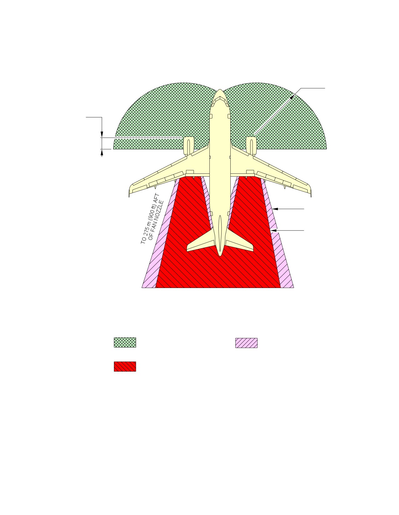
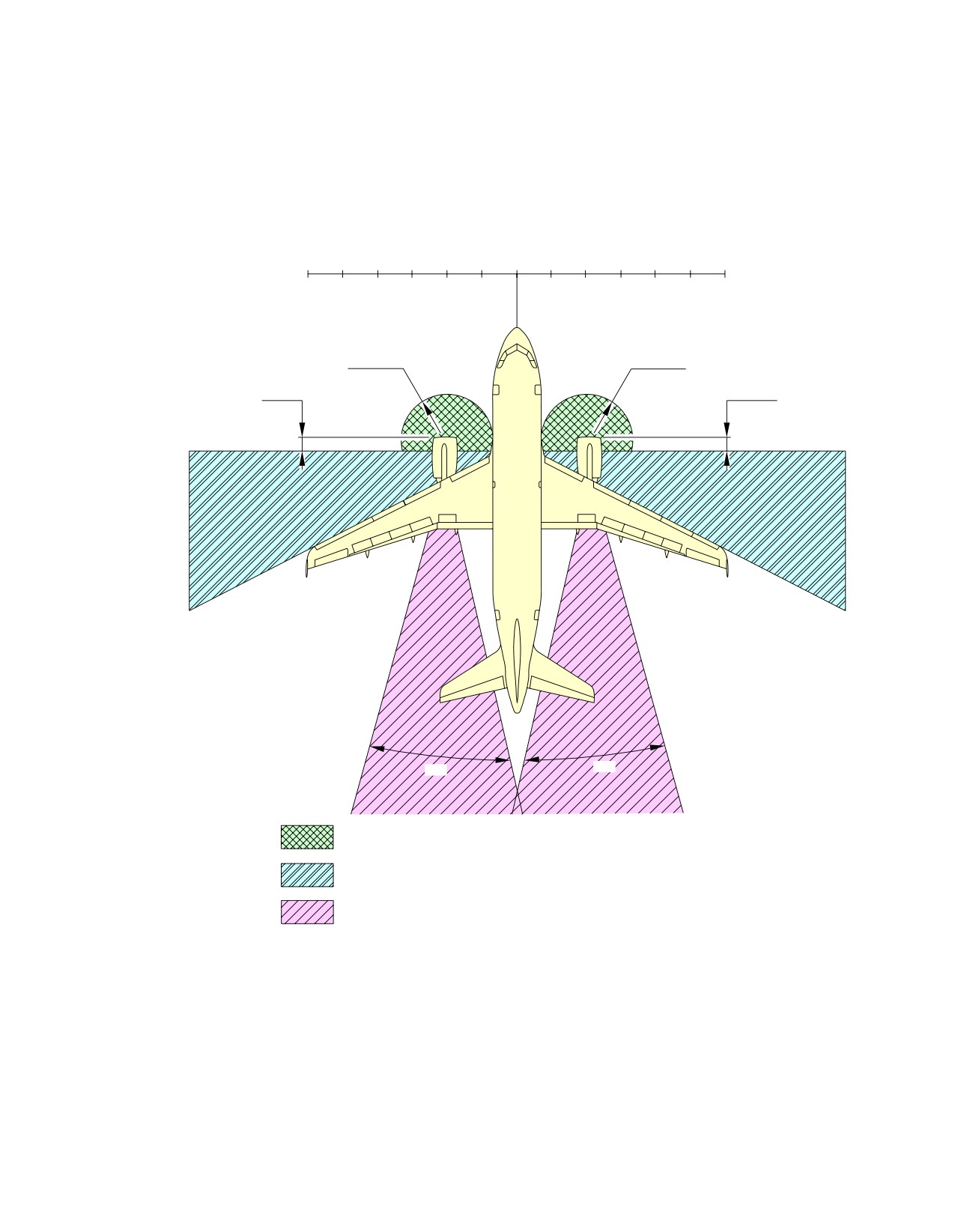
@A318
AIRCRAFT CHARACTERISTICS - AIRPORT AND MAINTENANCE PLANNING
**ON A/C A318-100
R = 5.9 m
(19.5 ft)
1.8 m
(6 ft)
40°
30°
TO 150 m (500 ft) AFT
OF FAN NOZZLE
INLET SUCTION DANGER
EXHAUST WAKE DANGER
AREA
AREA 65 MPH (105 km/h)
OR LESS
EXHAUST WAKE DANGER
AREA 65 MPH (105 km/h)
OR GREATER
N_AC_060302_1_0010101_01_01
Danger Areas of the Engines
CFM56 Series Engine
FIGURE-6-3-2-991-001-A01
Page 2
May 01/16
6-3-2
@A318
AIRCRAFT CHARACTERISTICS - AIRPORT AND MAINTENANCE PLANNING
**ON A/C A318-100
FEET
(METERS)
60
50
40
30
20
10
10
20
30
40
50
60
(18)
(15)
(12)
(9)
(6)
(3)
0
(3)
(6)
(9)
(12)
(15)
(18)
R = 20 ft
R = 20 ft
(6.10 m)
(6.10 m)
6 ft
6 ft
(1.83 m)
(1.83 m)
30°
30°
INTAKE SUCTION DANGER AREA
ENTRY CORRIDOR
EXHAUST DANGER AREA (AFT OF EXHAUST NOZZLE):
600 ft (183 m) − TAKE OFF POWER (20 kt HEADWIND)
N_AC_060302_1_0020101_01_01
Danger Areas of the Engines
PW 6000 Series Engine
FIGURE-6-3-2-991-002-A01
Page 3
May 01/16
6-3-2
@A318
AIRCRAFT CHARACTERISTICS - AIRPORT AND MAINTENANCE PLANNING
6-4-1
APU
**ON A/C A318-100
APU - APIC & GARRETT
1.
This section gives APU exhaust velocities and temperatures.
Page 1
May 01/16
6-4-1
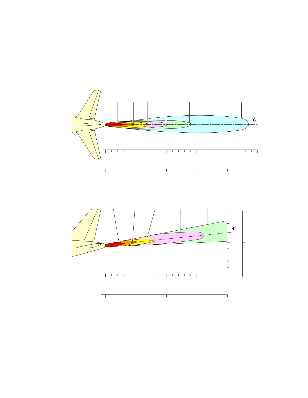
@A318
AIRCRAFT CHARACTERISTICS - AIRPORT AND MAINTENANCE PLANNING
**ON A/C A318-100
300°C
200°C
150°C
120°C
100°C
80°C
572°F
392°F
302°F
248°F
212°F
176°F
METERS
0
PLAN
5
10
15
20
25
FEET
0
16.404
32.808
49.212
65.616
82.02
HEIGHT
45 m/s
30 m/s
20 m/s
10 m/s
5 m/s
147 ft/s
98 ft/s
m
ft
65 ft/s
32 ft/s
16 ft/s
10
32.808
5
16.404
METERS
0
0
0
5
10
15
20
ELEVATION
FEET
0
16.404
32.808
49.212
65.616
N_AC_060401_1_0010101_01_00
Exhaust Velocities and Temperatures
APU -- APIC & GARRETT
FIGURE-6-4-1-991-001-A01
Page 2
May 01/16
6-4-1
@A318
AIRCRAFT CHARACTERISTICS - AIRPORT AND MAINTENANCE PLANNING
PAVEMENT DATA
7-1-0
General Information
**ON A/C A318-100
General Information
1.
A brief description of the pavement charts that follow will help in airport planning.
To aid in the interpolation between the discrete values shown, each aircraft configuration is shown
with a minimum range of five loads on the Main Landing Gear (MLG).
All curves on the charts represent data at a constant specified tire pressure with:
-
The aircraft loaded to the Maximum Ramp Weight (MRW),
-
The CG at its maximum permissible aft position.
Pavement requirements for commercial aircraft are derived from the static analysis of loads imposed
on the MLG struts.
Landing Gear Footprint:
Section 07-02-00 presents basic data on the landing gear footprint configuration, MRW and tire sizes
and pressures.
Maximum Pavement Loads:
Section 07-03-00 shows maximum vertical and horizontal pavement loads for certain critical
conditions at the tire-ground interfaces.
Landing Gear Loading on Pavement:
Section 07-04-00 contains charts to find these loads throughout the stability limits of the aircraft at
rest on the pavement.
These MLG loads are used as the point of entry to the pavement design charts which follow,
interpolating load values where necessary.
Flexible Pavement Requirements - US Army Corps of Engineers Design Method:
Section 07-05-00 uses procedures in Instruction Report No. S-77-1 ”Procedures for Development of
CBR Design Curves”, dated June 1977 and as modified according to the methods described in ICAO
Aerodrome Design Manual, Part 3. Pavements, 2nd Edition, 1983, Section 1.1 (The ACN-PCN
Method), and utilizing the alpha factors approved by ICAO in October 2007.
The report was prepared by the ”U.S. Army Corps Engineers Waterways Experiment Station, Soils
and Pavement Laboratory, Vicksburg, Mississippi”.
The line showing 10 000 coverages is used to calculate the Aircraft Classification Number (ACN).
Flexible Pavement Requirements - LCN Conversion Method:
Page 1
May 01/16
7-1-0
@A318
AIRCRAFT CHARACTERISTICS - AIRPORT AND MAINTENANCE PLANNING
The Load Classification Number (LCN) curves are no longer provided in section 07-06-00 since the
LCN system for reporting pavement strength is obsolete, having been replaced by the ICAO
recommended ACN/PCN system in 1983.
For questions regarding the LCN system, contact Airbus.
Rigid Pavement Requirements - PCA (Portland Cement Association) Design Method:
Section 07-07-00 gives the rigid pavement design curves that have been prepared with the use of the
Westergaard Equation.
This is in general accordance with the procedures outlined in the Portland Cement Association
publications, ”Design of Concrete Airport Pavement”, 1973 and ”Computer Program for Airport
Pavement Design” (Program PDILB), 1967 both by Robert G. Packard.
Rigid Pavement Requirements - LCN Conversion:
The Load Classification Number (LCN) curves are no longer provided in section 07-08-00 since the
LCN system for reporting pavement strength is obsolete, having been replaced by the ICAO
recommended ACN/PCN system in 1983.
For questions regarding the LCN system, contact Airbus.
ACN/PCN Reporting System:
Section 07-09-00 provides ACN data prepared according to the ACN/PCN system as referenced in
ICAO Annex 14, ”Aerodromes”, Volume 1 ”Aerodrome Design and Operations” Fourth Edition, July
2004, incorporating Amendments 1 to 6.
The ACN/PCN system provides a standardized international aircraft/pavement rating system
replacing the various S, T, TT, LCN, AUW, ISWL, etc., rating systems used throughout the world.
ACN is the Aircraft Classification Number and PCN is the corresponding Pavement Classification
Number.
An aircraft having an ACN less than or equal to the PCN can operate without restriction on the
pavement.
Numerically the ACN is two times the derived single wheel load expressed in thousands of kilograms.
The derived single wheel load is defined as the load on a single tire inflated to 1.25 MPa (181 psi)
that would have the same pavement requirements as the aircraft.
Computationally the ACN/PCN system uses PCA program PDILB for rigid pavements and S-77-1 for
flexible pavements to calculate ACN values.
The Airport Authority must decide on the method of pavement analysis and the results of their
evaluation shown as follows:
PCN
PAVEMENT
SUBGRADE
EVALUATION
TIRE PRESSURE CATEGORY
TYPE
CATEGORY
METHOD
R -- Rigid
A -- High
W -- No pressure limit
T -- Technical
X -- High pressure limited to 1.75
F -- Flexible
B -- Medium
U -- Using Aircraft
MPa (254 psi)
Page 2
May 01/16
7-1-0

@A318
AIRCRAFT CHARACTERISTICS - AIRPORT AND MAINTENANCE PLANNING
PCN
PAVEMENT
SUBGRADE
EVALUATION
TIRE PRESSURE CATEGORY
TYPE
CATEGORY
METHOD
Y -- Medium pressure limited to 1.25
C -- Low
MPa (181 psi)
Z -- Low pressure limited to 0.5 MPa
D -- Ultra Low
(73 psi)
For flexible pavements, the four subgrade categories (CBR) are:
- A. High Strength
CBR 15
- B. Medium Strength
CBR 10
- C. Low Strength
CBR 6
- D. Ultra Low Strength
CBR 3
For rigid pavements, the four subgrade categories (k) are:
- A. High Strength
k = 150 MN/m3 (550 pci)
- B. Medium Strength
k = 80 MN/m3 (300 pci)
- C. Low Strength
k = 40 MN/m3 (150 pci)
- D. Ultra Low Strength
k = 20 MN/m3 (75 pci)
Page 3
May 01/16
7-1-0
@A318
AIRCRAFT CHARACTERISTICS - AIRPORT AND MAINTENANCE PLANNING
7-2-0
Landing Gear Footprint
**ON A/C A318-100
Landing Gear Footprint
1.
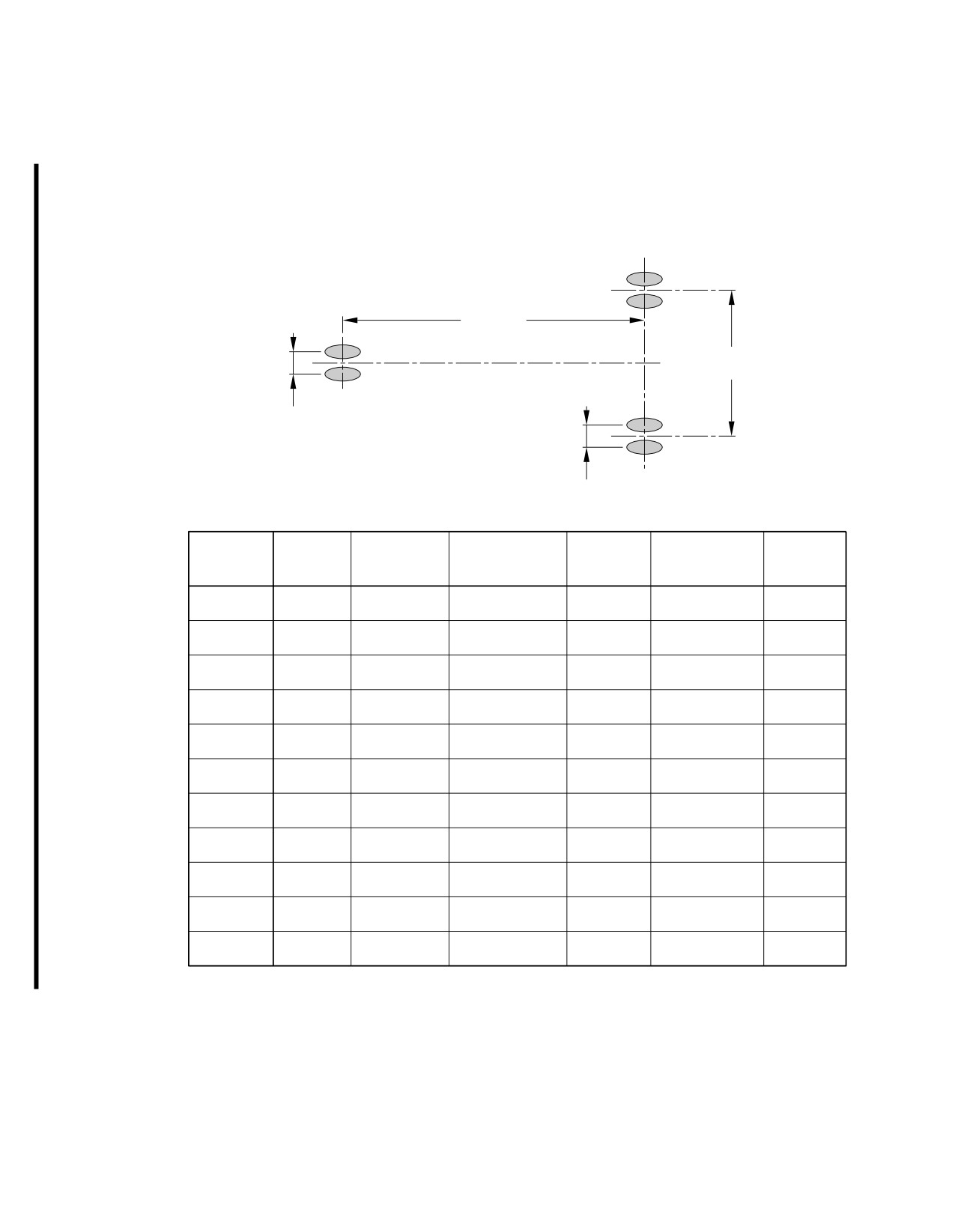
This section provides data about the landing gear footprint in relation to the aircraft MRW and tire
sizes and pressures.
The landing-gear footprint information is given for all the operational weight variants of the aircraft.
Page 1
May 01/16
7-2-0
@A318
AIRCRAFT CHARACTERISTICS - AIRPORT AND MAINTENANCE PLANNING
**ON A/C A318-100
10.252 m
(33.635 ft)
7.590 m
(24.901 ft)
0.500 m
(1.640 ft)
0.927 m
(3.041 ft)
PERCENTAGE
MAXIMUM
NOSE GEAR
MAIN GEAR
WEIGHT
OF WEIGHT
NOSE GEAR TIRE
MAIN GEAR TIRE
RAMP
TIRE
TIRE
VARIANT
ON MAIN
SIZE
SIZE
WEIGHT
PRESSURE
PRESSURE
GEAR GROUP
A318−100
59 400 kg
30x8.8R15
12.8 bar
46x17R20
11.4 bar
89.7%
WV000
(130 950 lb)
(30x8.8−15)
(186 psi)
(46x16−20)
(165 psi)
A318−100
61 900 kg
30x8.8R15
12.8 bar
46x17R20
11.4 bar
89.2%
WV001
(136 475 lb)
(30x8.8−15)
(186 psi)
(46x16−20)
(165 psi)
A318−100
63 400 kg
30x8.8R15
12.8 bar
46x17R20
11.4 bar
89.0%
WV002
(139 775 lb)
(30x8.8−15)
(186 psi)
(46x16−20)
(165 psi)
A318−100
64 900 kg
30x8.8R15
13.5 bar
46x17R20
12.4 bar
89.0%
WV003
(143 075 lb)
(30x8.8−15)
(196 psi)
(46x16−20)
(180 psi)
A318−100
66 400 kg
30x8.8R15
13.5 bar
46x17R20
12.4 bar
89.0%
WV004
(146 375 lb)
(30x8.8−15)
(196 psi)
(46x16−20)
(180 psi)
A318−100
68 400 kg
30x8.8R15
13.5 bar
46x17R20
12.4 bar
89.0%
WV005
(150 800 lb)
(30x8.8−15)
(196 psi)
(46x16−20)
(180 psi)
A318−100
56 400 kg
30x8.8R15
12.3 bar
46x17R20
10.2 bar
90.2%
WV006
(124 350 lb)
(30x8.8−15)
(178 psi)
(46x16−20)
(148 psi)
A318−100
61 400 kg
30x8.8R15
12.8 bar
46x17R20
11.4 bar
89.3%
WV007
(135 375 lb)
(30x8.8−15)
(186 psi)
(46x16−20)
(165 psi)
A318−100
64 400 kg
30x8.8R15
13.5 bar
46x17R20
12.4 bar
89.0%
WV008
(141 975 lb)
(30x8.8−15)
(196 psi)
(46x16−20)
(180 psi)
A318−100
66 400 kg
30x8.8R15
13.5 bar
46x17R20
12.4 bar
89.0%
WV009
(146 375 lb)
(30x8.8−15)
(196 psi)
(46x16−20)
(180 psi)
A318−100
68 400 kg
30x8.8R15
13.5 bar
46x17R20
12.4 bar
89.0%
WV010
(150 800 lb)
(30x8.8−15)
(196 psi)
(46x16−20)
(180 psi)
N_AC_070200_1_0010101_01_03
Landing Gear Footprint
FIGURE-7-2-0-991-001-A01
Page 2
May 01/16
7-2-0
@A318
AIRCRAFT CHARACTERISTICS - AIRPORT AND MAINTENANCE PLANNING
7-3-0
Maximum Pavement Loads
**ON A/C A318-100
Maximum Pavement Loads
1.
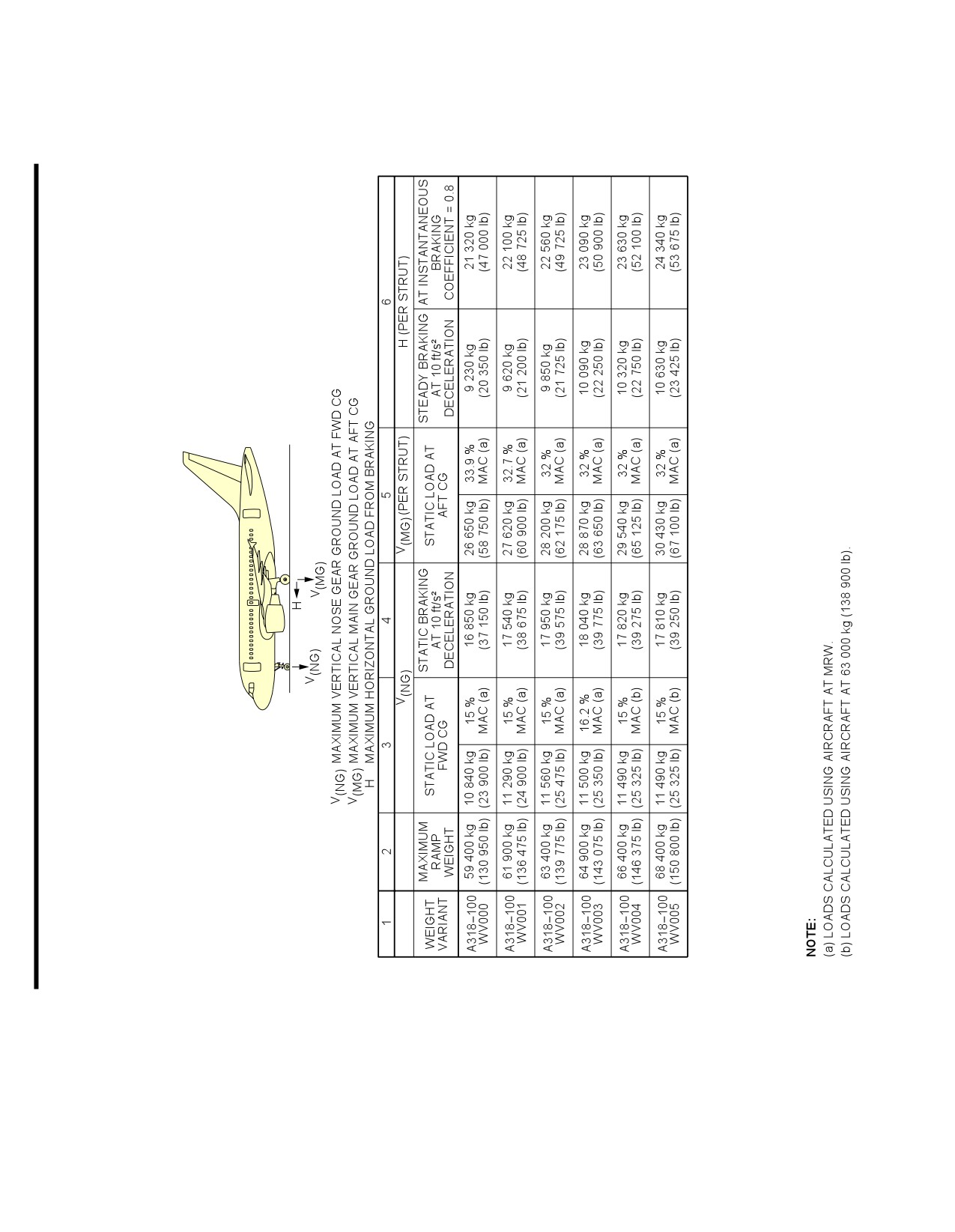
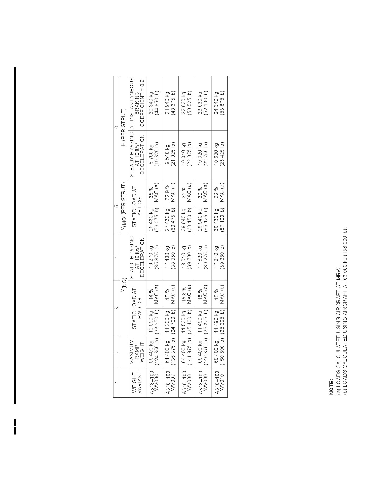
This section provides maximum vertical and horizontal pavement loads for some critical conditions at
the tire-ground interfaces.
The maximum pavement loads are given for all the operational weight variants of the aircraft.
Page 1
May 01/16
7-3-0
@A318
AIRCRAFT CHARACTERISTICS - AIRPORT AND MAINTENANCE PLANNING
**ON A/C A318-100
N_AC_070300_1_0200101_01_02
Maximum Pavement Loads
(Sheet 1 of 2)
FIGURE-7-3-0-991-020-A01
Page 2
May 01/16
7-3-0
@A318
AIRCRAFT CHARACTERISTICS - AIRPORT AND MAINTENANCE PLANNING
**ON A/C A318-100
N_AC_070300_1_0200102_01_00
Maximum Pavement Loads
(Sheet 2 of 2)
FIGURE-7-3-0-991-020-A01
Page 3
May 01/16
7-3-0
@A318
AIRCRAFT CHARACTERISTICS - AIRPORT AND MAINTENANCE PLANNING
7-4-0
Landing Gear Loading on Pavement
**ON A/C A318-100
Landing Gear Loading on Pavement
1.
Landing Gear Loading on Pavement
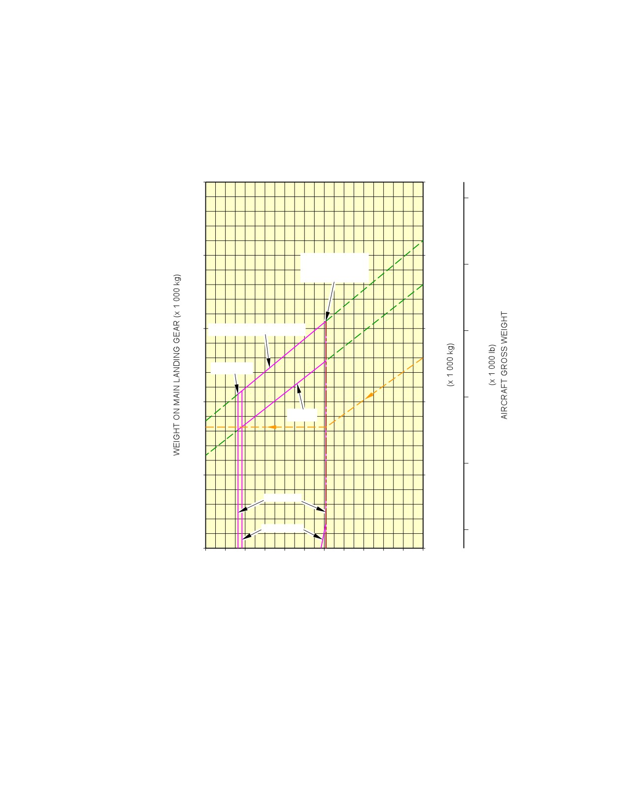
This section provides data about the landing gear loading on pavement.
The MLG loading on pavement graphs are given for the weight variants that produce (at the MRW
and maximum aft CG) the lowest MLG load and the highest MLG load for each type of aircraft.
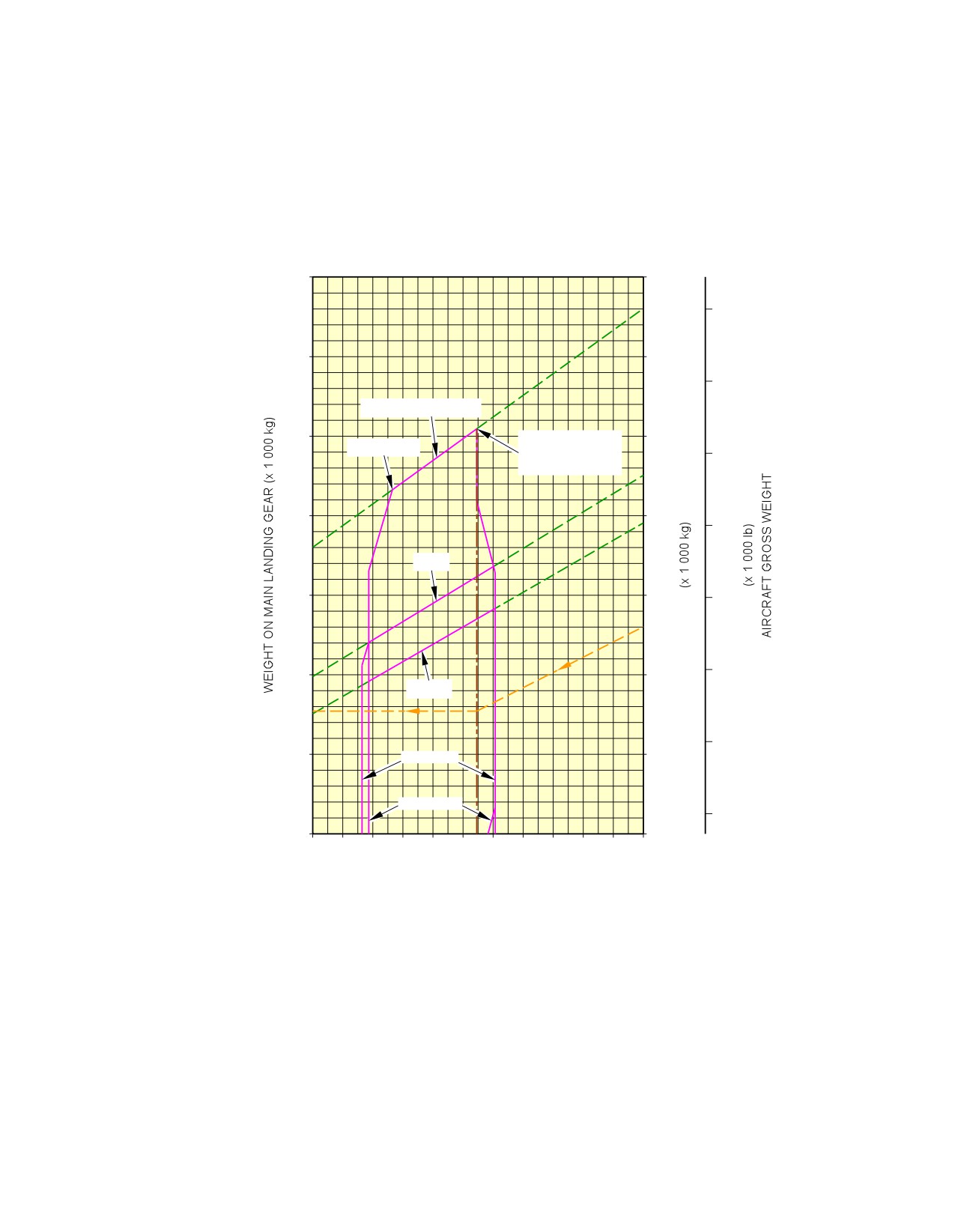
Example, see FIGURE 7-4-0-991-001-A, calculation of the total weight on the MLG for:
-
An aircraft with a MRW of 56 400 kg (124 350 lb),
-
The aircraft gross weight is 48 000 kg (105 825 lb),
-
A percentage of weight on the MLG of 90.2% (percentage of weight on the MLG at MRW and
maximum aft CG).
The total weight on the MLG group is 43 280 kg (95 425 lb).
NOTE : The CG in the figure title is the CG used for ACN/LCN calculation.
Page 1
May 01/16
7-4-0
@A318
AIRCRAFT CHARACTERISTICS - AIRPORT AND MAINTENANCE PLANNING
**ON A/C A318-100
60
60
130
55
55
CG FOR ACN
120
CALCULATION
35% MAC
50
MTOW/MLW − 56 000 kg
50
110
14% MAC
100
45
45
MZFW
90
40
40
LANDING
TAKE OFF
80
35
35
78
80
82
84
86
88
90
92
94
96
98
100
PERCENTAGE OF WEIGHT ON MAIN GEAR
N_AC_070400_1_0010101_01_00
Landing Gear Loading on Pavement
WV006, MRW 56 400 kg, CG 35%
FIGURE-7-4-0-991-001-A01
Page 2
May 01/16
7-4-0
@A318
AIRCRAFT CHARACTERISTICS - AIRPORT AND MAINTENANCE PLANNING
**ON A/C A318-100
70
70
150
65
65
140
MTOW − 68 000 kg
60
60
CG FOR ACN
18.7% MAC
CALCULATION
130
32% MAC
55
55
120
MLW
50
50
110
100
45
45
MZFW
90
40
LANDING
40
TAKE OFF
80
35
35
78
80
82
84
86
88
90
92
94
96
98
100
PERCENTAGE OF WEIGHT ON MAIN GEAR
N_AC_070400_1_0020101_01_00
Landing Gear Loading on Pavement
WV005, MRW 68 400 kg, CG 32%
FIGURE-7-4-0-991-002-A01
Page 3
May 01/16
7-4-0
@A318
AIRCRAFT CHARACTERISTICS - AIRPORT AND MAINTENANCE PLANNING
7-5-0
Flexible Pavement Requirements - U.S. Army Corps of Engineers Design Method
**ON A/C A318-100
Flexible Pavement Requirements - US Army Corps of Engineers Design Method
1.
This section provides data about the flexible pavement requirements.
The flexible pavement requirement graphs are given at standard tire pressure for the weight variants
producing (at the MRW and maximum aft CG) the lowest MLG load and the highest MLG load for
each type of aircraft.
They are calculated with the US Army Corps of Engineers Design Method.
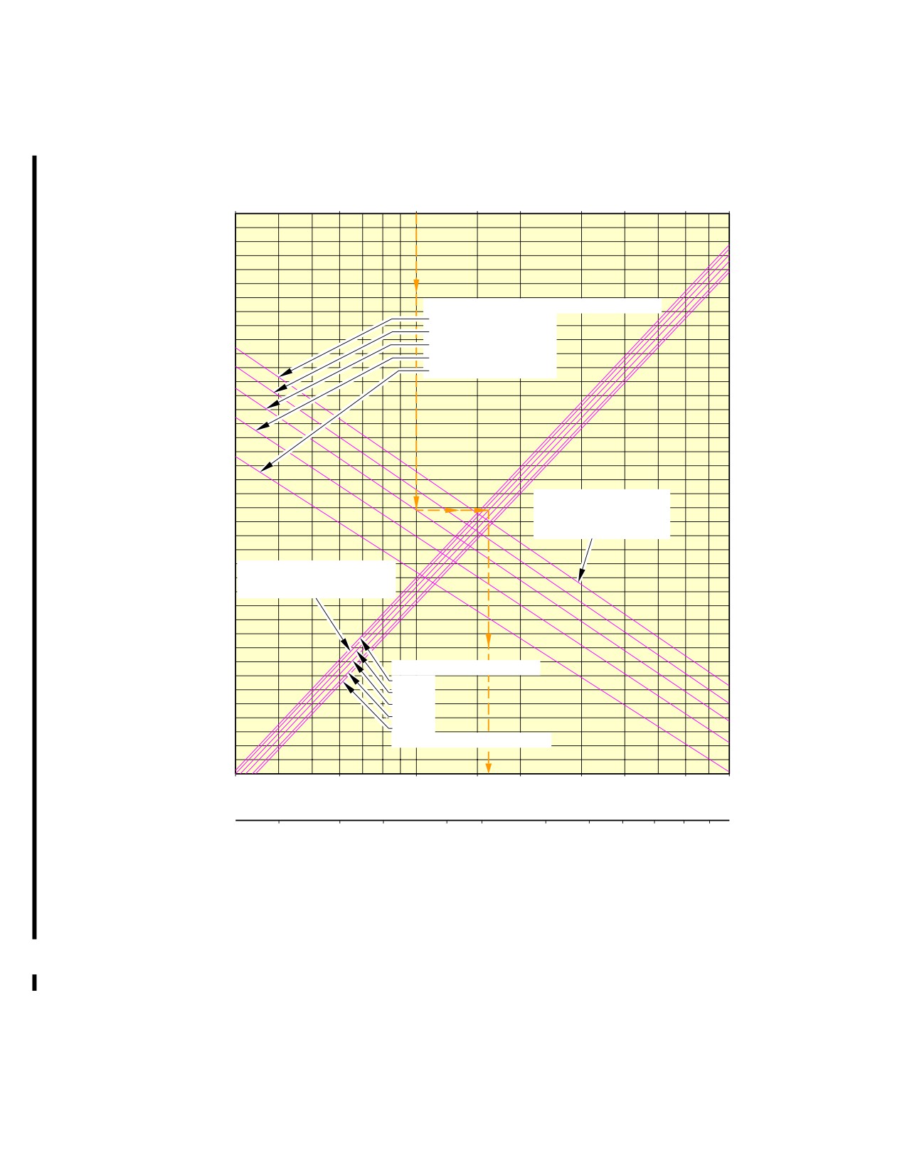
To find a flexible pavement thickness, you must know the Subgrade Strength (CBR), the annual
departure level and the weight on one MLG.
The line that shows 10 000 coverages is used to calculate the Aircraft Classification Number (ACN).
The procedure that follows is used to develop flexible pavement design curves:
-
With the scale for pavement thickness at the bottom and the scale for CBR at the top, a random
line is made to show 10 000 coverages,
-
A plot is then made of the incremental values of the weight on the MLG,
-
Annual departure lines are made based on the load lines of the weight on the MLG that is shown
on the graph.
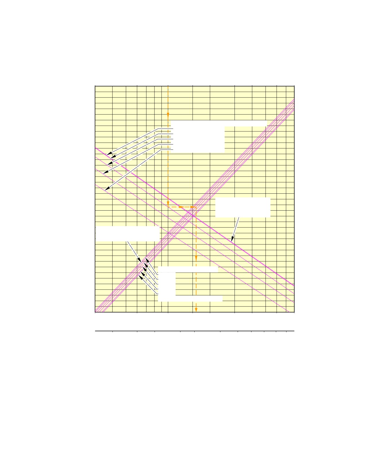
Example, see FIGURE 7-5-0-991-001-A, calculation of the thickness of the flexible pavement for
MLG:
-
An aircraft with a MRW of 56 400 kg (124 350 lb),
-
A ”CBR” value of 10,
-
An annual departure level of 3 000,
-
The load on one MLG of 20 000 kg (44 100 lb).
The required flexible pavement thickness is 40.3 cm (16 in).
NOTE : The CG in the figure title is the CG used for ACN calculation.
Page 1
May 01/16
7-5-0
@A318
AIRCRAFT CHARACTERISTICS - AIRPORT AND MAINTENANCE PLANNING
**ON A/C A318-100
SUBGRADE STRENGTH − CBR
3
6
10
15
20
30
40
60
80
WEIGHT ON ONE MAIN LANDING GEAR
25 430 kg (56 075 lb)
25 000 kg (55 125 lb)
20 000 kg (44 100 lb)
15 000 kg (33 075 lb)
(22 050 lb)
10 000 kg
MAXIMUM POSSIBLE
MAIN GEAR LOAD
AT MAXIMUM RAMP
WEIGHT AND AFT CG
10 000 COVERAGES USED
FOR ACN CALCULATIONS
ALPHA FACTOR = 0.9
ANNUAL DEPARTURES*
1 200
3 000
6 000
15 000
25 000
*20 YEAR PAVEMENT LIFE
3
6
10
15
20
30
40
60
80
(in)
10
15
20
30
40
60
80
100
120
150 180
(cm)
FLEXIBLE PAVEMENT THICKNESS
46x17R20 (46x16−20) TIRES
TIRE PRESSURE CONSTANT AT 10.2 bar (148 psi)
N_AC_070500_1_0010101_01_00
Flexible Pavement Requirements
WV006, MRW 56 400 kg, CG 35 %
FIGURE-7-5-0-991-001-A01
Page 2
May 01/16
7-5-0
@A318
AIRCRAFT CHARACTERISTICS - AIRPORT AND MAINTENANCE PLANNING
**ON A/C A318-100
SUBGRADE STRENGTH − CBR
3
6
10
15
20
30
40
60
80
WEIGHT ON ONE MAIN LANDING GEAR
30 430 kg (67 075 lb)
25 000 kg (55 125 lb)
20 000 kg (44 100 lb)
15 000 kg (33 075 lb)
(22 050 lb)
10 000 kg
MAXIMUM POSSIBLE
MAIN GEAR LOAD
AT MAXIMUM RAMP
WEIGHT AND AFT CG
10 000 COVERAGES USED
FOR ACN CALCULATIONS
ALPHA FACTOR = 0.9
ANNUAL DEPARTURES*
1 200
3 000
6 000
15 000
25 000
*20 YEAR PAVEMENT LIFE
3
6
10
15
20
30
40
60
80
(in)
10
15
20
30
40
60
80
100
120
150 180
(cm)
FLEXIBLE PAVEMENT THICKNESS
46x17R20 (46x16−20) TIRES
TIRE PRESSURE CONSTANT AT 12.4 bar (180 psi)
N_AC_070500_1_0020101_01_00
Flexible Pavement Requirements
WV005, WV010, MRW 68 400 kg, CG 32 %
FIGURE-7-5-0-991-002-A01
Page 3
May 01/16
7-5-0
@A318
AIRCRAFT CHARACTERISTICS - AIRPORT AND MAINTENANCE PLANNING
7-6-0
Flexible Pavement Requirements - LCN Conversion
**ON A/C A318-100
Flexible Pavement Requirements - LCN Conversion
1.
The Load Classification Number (LCN) curves are no longer provided in section 07-06-00 since the
LCN system for reporting pavement strength is obsolete, having been replaced by the ICAO
recommended ACN/PCN system in 1983.
For questions regarding the LCN system, contact Airbus.
Page 1
May 01/16
7-6-0
@A318
AIRCRAFT CHARACTERISTICS - AIRPORT AND MAINTENANCE PLANNING
7-7-0
Rigid Pavement Requirements - Portland Cement Association Design Method
**ON A/C A318-100
Rigid Pavement Requirements - Portland Cement Association Design Method
1.
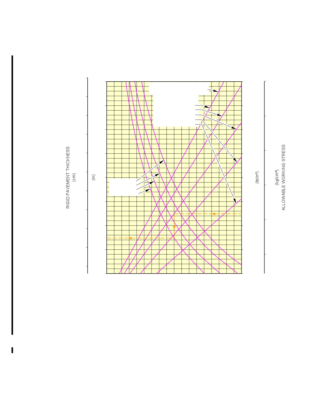
This section provides data about the rigid pavement requirements for the PCA (Portland Cement
Association) design method.
The rigid pavement requirement graphs are given at standard tire pressure for the weight variants
producing (at the MRW and maximum aft CG) the lowest MLG load and the highest MLG load for
each A/C type.
They are calculated with the PCA design method.
To find a rigid pavement thickness, you must know the Subgrade Modulus (k), the permitted working
stress and the weight on one MLG.
The procedure that follows is used to develop rigid pavement design curves:
-
With the scale for pavement thickness on the left and the scale for permitted working stress on
the right, a random load line is made. This represents the MLG maximum weight to be shown,
-
A plot is then made of all values of the subgrade modulus (k values),
-
More load lines for the incremental values of the weight on the MLG are made based on the
curve for k = 150 MN/m3, which is already shown on the graph.
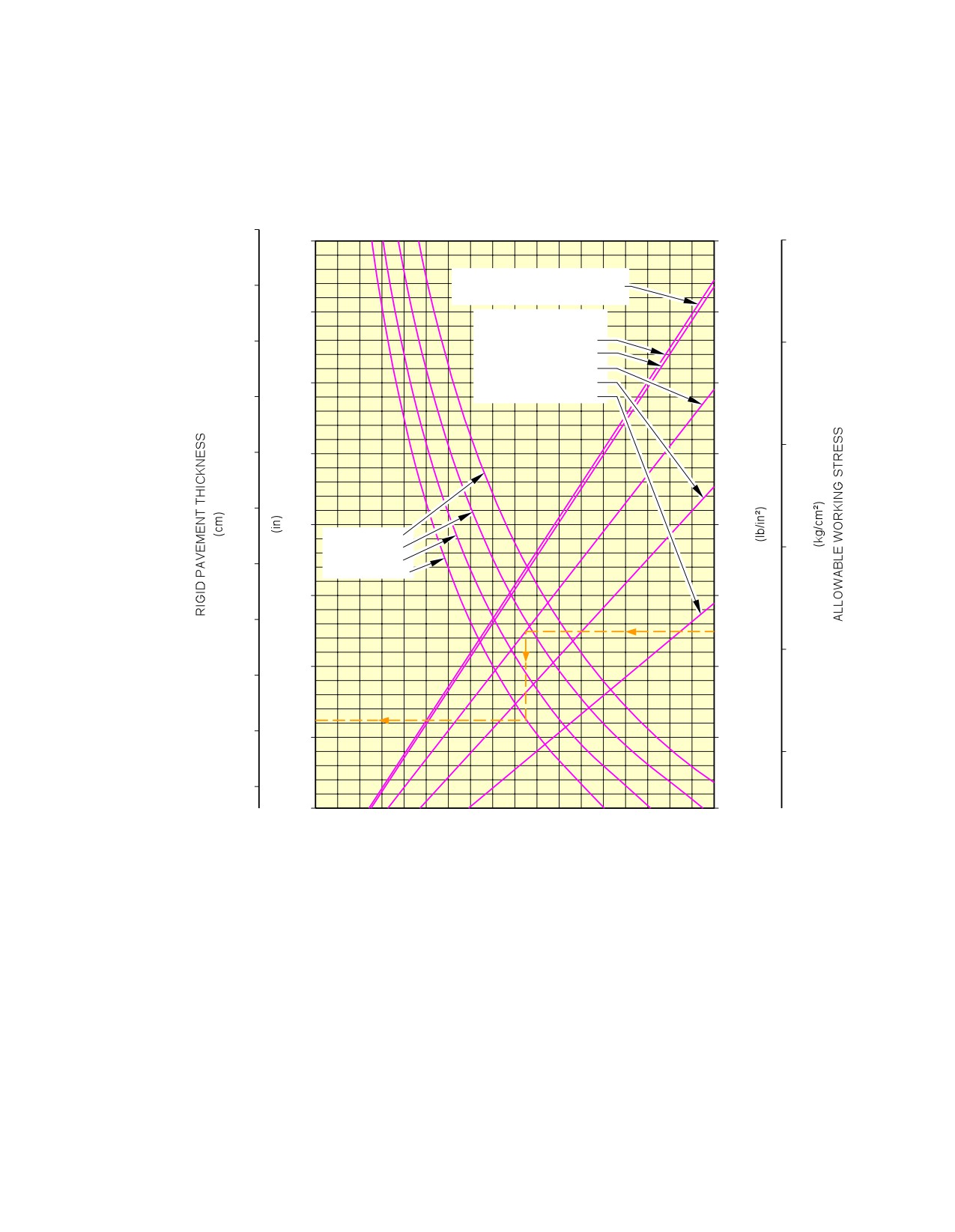
Example, see FIGURE 7-7-0-991-003-A, calculation of the thickness of the rigid pavement for the
MLG:
-
An aircraft with a MRW of 56 400 kg (124 350 lb),
-
A k value of 150 MN/m3 (550 lbf/in3),
-
A permitted working stress of 31.64 kg/cm2 (450 lb/in2),
-
The load on one MLG is 20 000 kg (44 100 lb).
The required rigid pavement thickness is 181 mm (7 in).
NOTE : The CG in the figure title is the CG used for ACN calculation.
Page 1
May 01/16
7-7-0
@A318
AIRCRAFT CHARACTERISTICS - AIRPORT AND MAINTENANCE PLANNING
**ON A/C A318-100
46x17R20 (46x16−20) TIRES
TIRE PRESSURE CONSTANT AT 10.2 bar (148 psi)
36
14
1 000
70
MAXIMUM POSSIBLE MAIN
34
GEAR LOAD AT MAXIMUM
RAMP WEIGHT AND AFT CG
13
WEIGHT ON ONE
900
MAIN LANDING GEAR
32
25 430 kg (56 075 lb)
60
25 000 kg (55 125 lb)
20 000 kg (44 100 lb)
12
15 000 kg (33 075 lb)
800
30
10 000 kg (22 050 lb)
50
28
11
700
26
10
600
k = 20 MN/m³
k = 40 MN/m³
40
k = 80 MN/m³
24
k = 150 MN/m³
9
500
22
30
8
400
20
18
7
300
20
16
6
200
NOTE:
REFERENCE:
THE VALUES OBTAINED BY USING
"DESIGN OF CONCRETE AIRPORT
THE MAXIMUM LOAD REFERENCE
PAVEMENTS" AND "COMPUTER
LINE AND ANY VALUES FOR k ARE
PROGRAM FOR AIRPORT
EXACT.
PAVEMENT DESIGN − PROGRAM
FOR LOADS LESS THAN MAXIMUM,
PDILB" PORTLAND CEMENT
THE CURVES ARE EXACT FOR k =
ASSOCIATION.
80 MN/m³ BUT DEVIATE SLIGHTLY
FOR ANY OTHER VALUES OF k.
N_AC_070700_1_0030101_01_00
Rigid Pavement Requirements
WV006, MRW 56 400 kg, CG 35 %
FIGURE-7-7-0-991-003-A01
Page 2
May 01/16
7-7-0
@A318
AIRCRAFT CHARACTERISTICS - AIRPORT AND MAINTENANCE PLANNING
**ON A/C A318-100
46x17R20 (46x16−20) TIRES
TIRE PRESSURE CONSTANT AT 12.4 bar (180 psi)
36
14
1 000
70
MAXIMUM POSSIBLE MAIN
GEAR LOAD AT MAXIMUM
RAMP WEIGHT AND AFT CG
34
WEIGHT ON ONE
MAIN LANDING GEAR
13
30 430 kg (67 100 lb)
900
25 000 kg (55 125 lb)
32
20 000 kg (44 100 lb)
60
15 000 kg (33 075 lb)
10 000 kg (22 050 lb)
12
800
30
50
28
11
700
26
10
600
k = 20 MN/m³
k = 40 MN/m³
40
k = 80 MN/m³
24
k = 150 MN/m³
9
500
22
30
8
400
20
18
7
300
20
16
6
200
NOTE:
REFERENCE:
THE VALUES OBTAINED BY USING
"DESIGN OF CONCRETE AIRPORT
THE MAXIMUM LOAD REFERENCE
PAVEMENTS" AND "COMPUTER
LINE AND ANY VALUES FOR k ARE
PROGRAM FOR AIRPORT
EXACT.
PAVEMENT DESIGN − PROGRAM
FOR LOADS LESS THAN MAXIMUM,
PDILB" PORTLAND CEMENT
THE CURVES ARE EXACT FOR k =
ASSOCIATION.
80 MN/m³ BUT DEVIATE SLIGHTLY
FOR ANY OTHER VALUES OF k.
N_AC_070700_1_0040101_01_00
Rigid Pavement Requirements
WV005, WV010, MRW 68 400 kg, CG 32 %
FIGURE-7-7-0-991-004-A01
Page 3
May 01/16
7-7-0
@A318
AIRCRAFT CHARACTERISTICS - AIRPORT AND MAINTENANCE PLANNING
7-8-0
Rigid Pavement Requirements - LCN Conversion
**ON A/C A318-100
Rigid Pavement Requirements - LCN Conversion
1.
The Load Classification Number (LCN) curves are no longer provided in section 07-08-00 since the
LCN system for reporting pavement strength is obsolete, having been replaced by the ICAO
recommended ACN/PCN system in 1983.
For questions regarding the LCN system, contact Airbus.
Page 1
May 01/16
7-8-0
@A318
AIRCRAFT CHARACTERISTICS - AIRPORT AND MAINTENANCE PLANNING
7-9-0
ACN/PCN Reporting System - Flexible and Rigid Pavements
**ON A/C A318-100
Aircraft Classification Number - Flexible and Rigid Pavements
1.
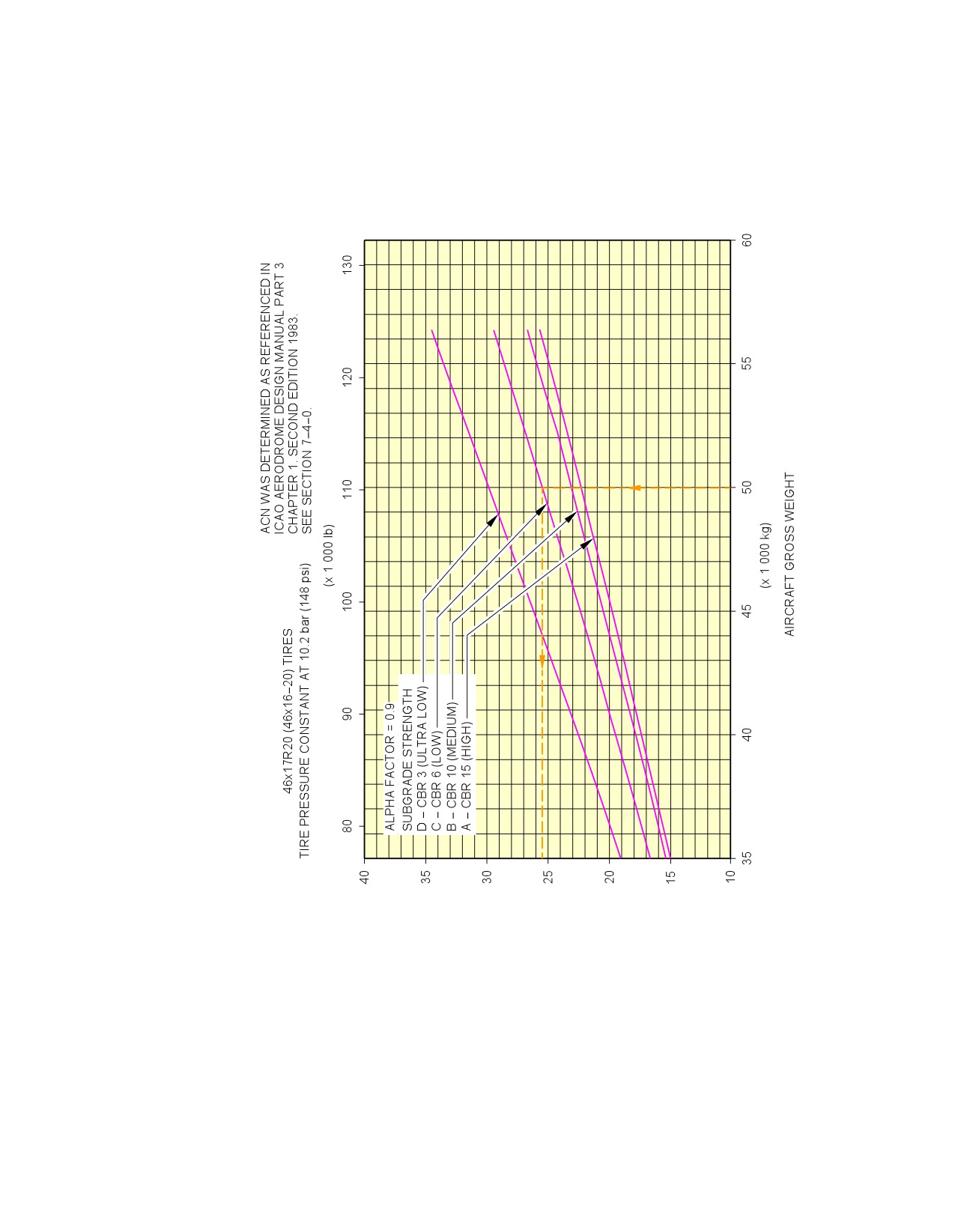
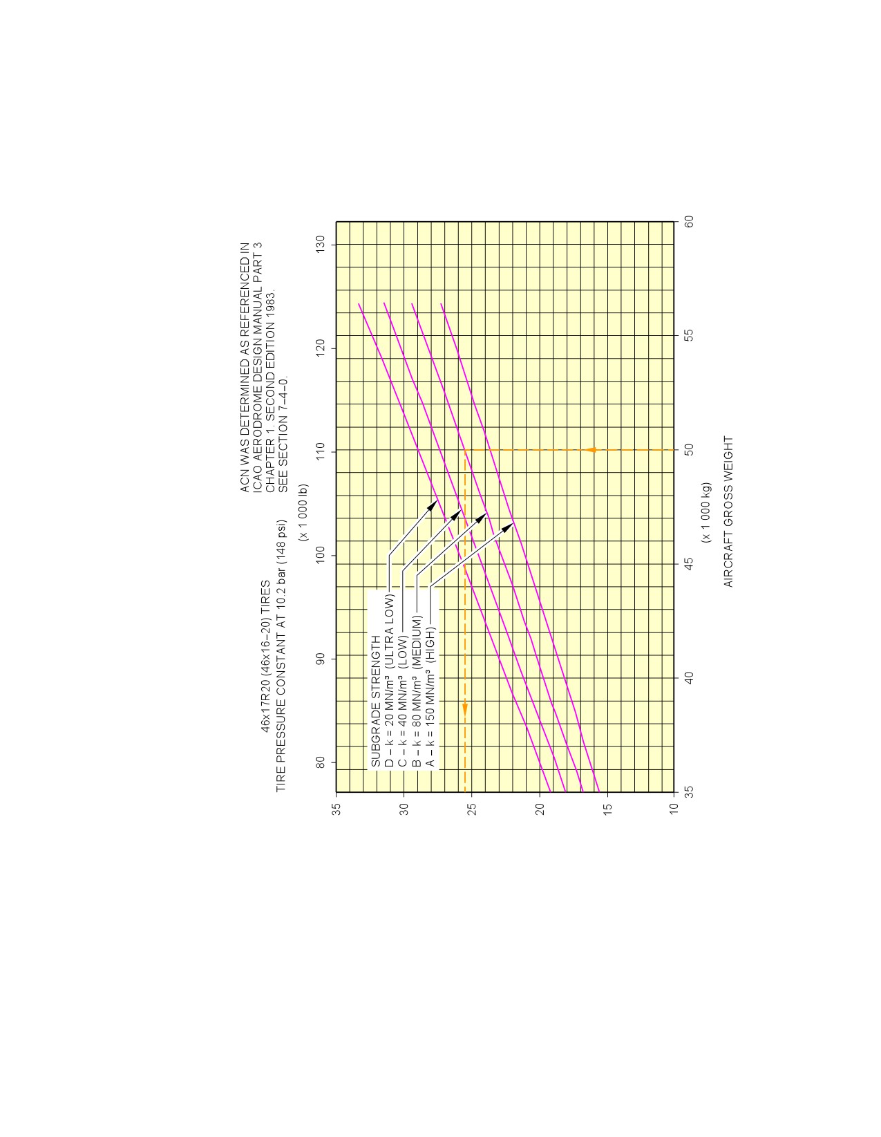
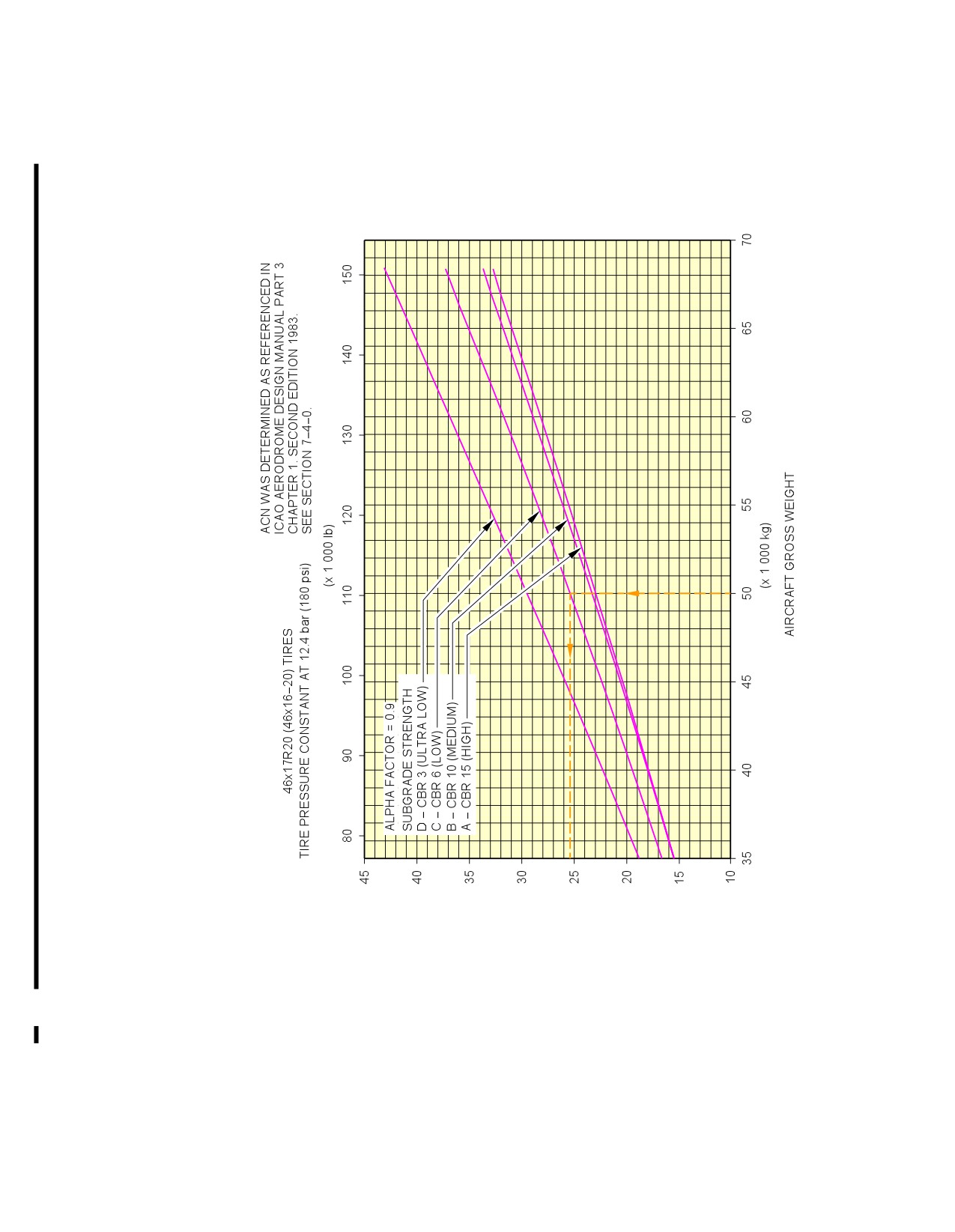
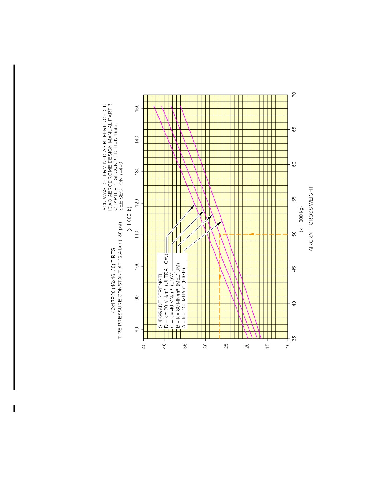
This section provides data about the Aircraft Classification Number (ACN) for an aircraft gross
weight in relation to a subgrade strength value for flexible and rigid pavement.
The flexible and rigid pavement requirement graphs are given at standard tire pressure for the weight
variants producing (at the MRW and maximum aft CG) the lowest MLG load and the highest MLG
load for each type of aircraft.
To find the ACN of an aircraft on flexible and rigid pavement, you must know the aircraft gross
weight and the subgrade strength.
NOTE : An aircraft with an ACN equal to or less than the reported PCN can operate on that
pavement, subject to any limitation on the tire pressure.
(Ref: ICAO Aerodrome Design Manual, Part 3, Chapter 1, Second Edition 1983).
Example, see FIGURE 7-9-0-991-002-A (sheet 1), calculation of the ACN for flexible pavement for:
-
An aircraft with a MRW of 56 400 kg (124 350 lb),
-
An aircraft gross weight of 50 000 kg (110 225 lb),
-
A low subgrade strength (code C).
The ACN for flexible pavement is 26.
Example, see FIGURE 7-9-0-991-002-A (sheet 2), calculation of the ACN for rigid pavement for:
-
An aircraft with a MRW of 56 400 kg (124 350 lb),
-
An aircraft gross weight of 50 000 kg (110 225 lb),
-
A medium subgrade strength (code B).
The ACN for rigid pavement is 26.
2.
Aircraft Classification Number - ACN table
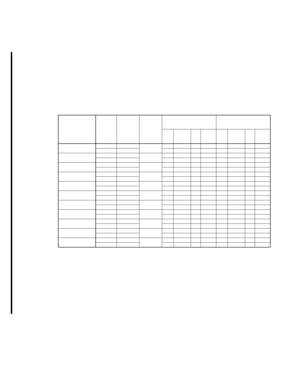
The table in FIGURE 7-9-0-991-001-A provide ACN data in tabular format similar to the one used by
ICAO in the ”Aerodrome Design Manual Part 3, Pavements - Edition 1983” for all the operational
weight variants of the aircraft.
As an approximation, use a linear interpolation in order to get the ACN at the required operating
weight using the following equation:
-
ACN = ACN min + (ACN max - ACN min) x (Operating weight - 39 000 kg)/(MRW - 39 000
kg)
As an approximation, also use a linear interpolation in order to get the aircraft weight at the
pavement PCN using the following equation:
-
Operating weight = 39 000 kg + (MRW - 39 000 kg) x (PCN - ACN min)/(ACN max - ACN
min)
With ACN max: ACN calculated at the MRW in the table and with ACN min: ACN calculated at 39
000 kg.
Page 1
May 01/16
7-9-0
@A318
AIRCRAFT CHARACTERISTICS - AIRPORT AND MAINTENANCE PLANNING
NOTE : The CG in the figure title is the CG used for ACN calculation.
Page 2
May 01/16
7-9-0
@A318
AIRCRAFT CHARACTERISTICS - AIRPORT AND MAINTENANCE PLANNING
**ON A/C A318-100
ACN FOR
ACN FOR
LOAD ON
RIGID PAVEMENT
FLEXIBLE PAVEMENT
TIRE
SUBGRADES − MN/m³
SUBGRADES − CBR
WEIGHT
ALL UP
ONE MAIN
PRESSURE
VARIANT
MASS (kg)
GEAR LEG
ULTRA
ULTRA
(MPa)
(%)
HIGH
MEDIUM
LOW
HIGH
MEDIUM
LOW
−LOW
−LOW
150
80
40
15
10
6
20
3
A318−100
59 400
44.9
30
32
34
36
28
29
32
37
1.14
WV000
39 000
44.8
18
20
21
22
17
18
19
22
A318−100
61 900
44.6
31
33
36
37
29
30
33
38
1.14
WV001
39 000
44.6
18
19
21
22
17
17
19
22
A318−100
63 400
44.5
32
34
36
38
30
31
34
39
1.14
WV002
39 000
44.4
18
19
21
22
17
17
19
22
A318−100
64 900
44.5
34
36
38
40
31
32
35
41
1.24
WV003
39 000
44.4
19
20
21
22
17
18
19
22
A318−100
66 400
44.5
35
37
39
41
32
33
36
42
1.24
WV004
39 000
44.4
19
20
21
22
17
18
19
22
A318−100
68 400
44.5
36
38
41
43
33
34
37
43
1.24
WV005
39 000
44.4
19
20
21
22
17
18
19
22
A318−100
56 400
45.1
27
29
32
33
26
27
30
35
1.02
WV006
39 000
45.1
18
19
21
22
17
17
19
22
A318−100
61 400
44.7
31
33
35
37
29
30
33
38
1.14
WV007
39 000
44.6
18
20
21
22
17
17
19
22
A318−100
64 400
44.5
34
36
38
40
31
31
35
40
1.24
WV008
39 000
44.4
19
20
21
22
17
18
19
22
A318−100
66 400
44.5
35
37
39
41
32
33
36
42
1.24
WV009
39 000
44.4
19
20
21
22
17
18
19
22
A318−100
68 400
44.5
36
38
41
43
33
34
37
43
1.24
WV010
39 000
44.4
19
20
21
22
17
18
19
22
N_AC_070900_1_0010101_01_01
Aircraft Classification Number
ACN Table
FIGURE-7-9-0-991-001-A01
Page 3
May 01/16
7-9-0
@A318
AIRCRAFT CHARACTERISTICS - AIRPORT AND MAINTENANCE PLANNING
**ON A/C A318-100
AIRCRAFT CLASSIFICATION NUMBER (ACN)
N_AC_070900_1_0020101_01_00
Aircraft Classification Number
Flexible Pavement - WV006, MRW 56 400 kg, CG 35 % (Sheet 1 of 2)
FIGURE-7-9-0-991-002-A01
Page 4
May 01/16
7-9-0
@A318
AIRCRAFT CHARACTERISTICS - AIRPORT AND MAINTENANCE PLANNING
**ON A/C A318-100
AIRCRAFT CLASSIFICATION NUMBER (ACN)
N_AC_070900_1_0020102_01_00
Aircraft Classification Number
Rigid Pavement - WV006, MRW 56 400 kg, CG 35 % (Sheet 2 of 2)
FIGURE-7-9-0-991-002-A01
Page 5
May 01/16
7-9-0
@A318
AIRCRAFT CHARACTERISTICS - AIRPORT AND MAINTENANCE PLANNING
**ON A/C A318-100
AIRCRAFT CLASSIFICATION NUMBER (ACN)
N_AC_070900_1_0030101_01_00
Aircraft Classification Number
Flexible Pavement - WV005, WV010, MRW 68 400 kg, CG 32 % (Sheet 1 of 2)
FIGURE-7-9-0-991-003-A01
Page 6
May 01/16
7-9-0
@A318
AIRCRAFT CHARACTERISTICS - AIRPORT AND MAINTENANCE PLANNING
**ON A/C A318-100
AIRCRAFT CLASSIFICATION NUMBER (ACN)
N_AC_070900_1_0030102_01_00
Aircraft Classification Number
Rigid Pavement - WV005, WV010, MRW 68 400 kg, CG 32 % (Sheet 2 of 2)
FIGURE-7-9-0-991-003-A01
Page 7
May 01/16
7-9-0
@A318
AIRCRAFT CHARACTERISTICS - AIRPORT AND MAINTENANCE PLANNING
SCALED DRAWINGS
8-0-0
SCALED DRAWINGS
**ON A/C A318-100
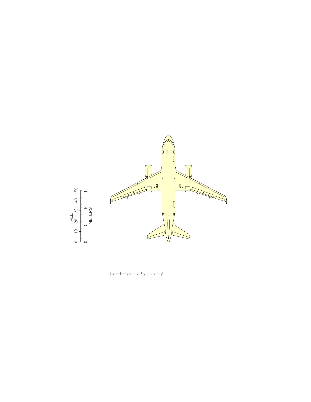
Scaled Drawings
1.
This section provides the scaled drawings.
NOTE : When printing this drawing, make sure to adjust for proper scaling.
Page 1
May 01/16
8-0-0
@A318
AIRCRAFT CHARACTERISTICS - AIRPORT AND MAINTENANCE PLANNING
**ON A/C A318-100
FEET
0
10
20
30
40
50
0
5
10
15
METERS
NOTE: WHEN PRINTING THIS DRAWING, MAKE SURE TO ADJUST FOR PROPER SCALING.
N_AC_080000_1_0010101_01_00
Scaled Drawing
FIGURE-8-0-0-991-001-A01
Page 2
May 01/16
8-0-0
@A318
AIRCRAFT CHARACTERISTICS - AIRPORT AND MAINTENANCE PLANNING
AIRCRAFT RESCUE AND FIRE FIGHTING
10-0-0
AIRCRAFT RESCUE AND FIRE FIGHTING
**ON A/C A318-100
Aircraft Rescue and Fire Fighting
1.
Aircraft Rescue and Fire Fighting Charts
This sections provides data related to aircraft rescue and fire fighting.
The figures contained in this section are the figures that are in the Aircraft Rescue and Fire Fighting
Charts poster available for download on AIRBUSWorld and the Airbus website.
Page 1
May 01/16
10-0-0
@A318
AIRCRAFT CHARACTERISTICS - AIRPORT AND MAINTENANCE PLANNING
**ON A/C A318-100
N_AC_100000_1_0010101_01_04
Front Page
FIGURE-10-0-0-991-001-A01
Page 2
May 01/16
10-0-0
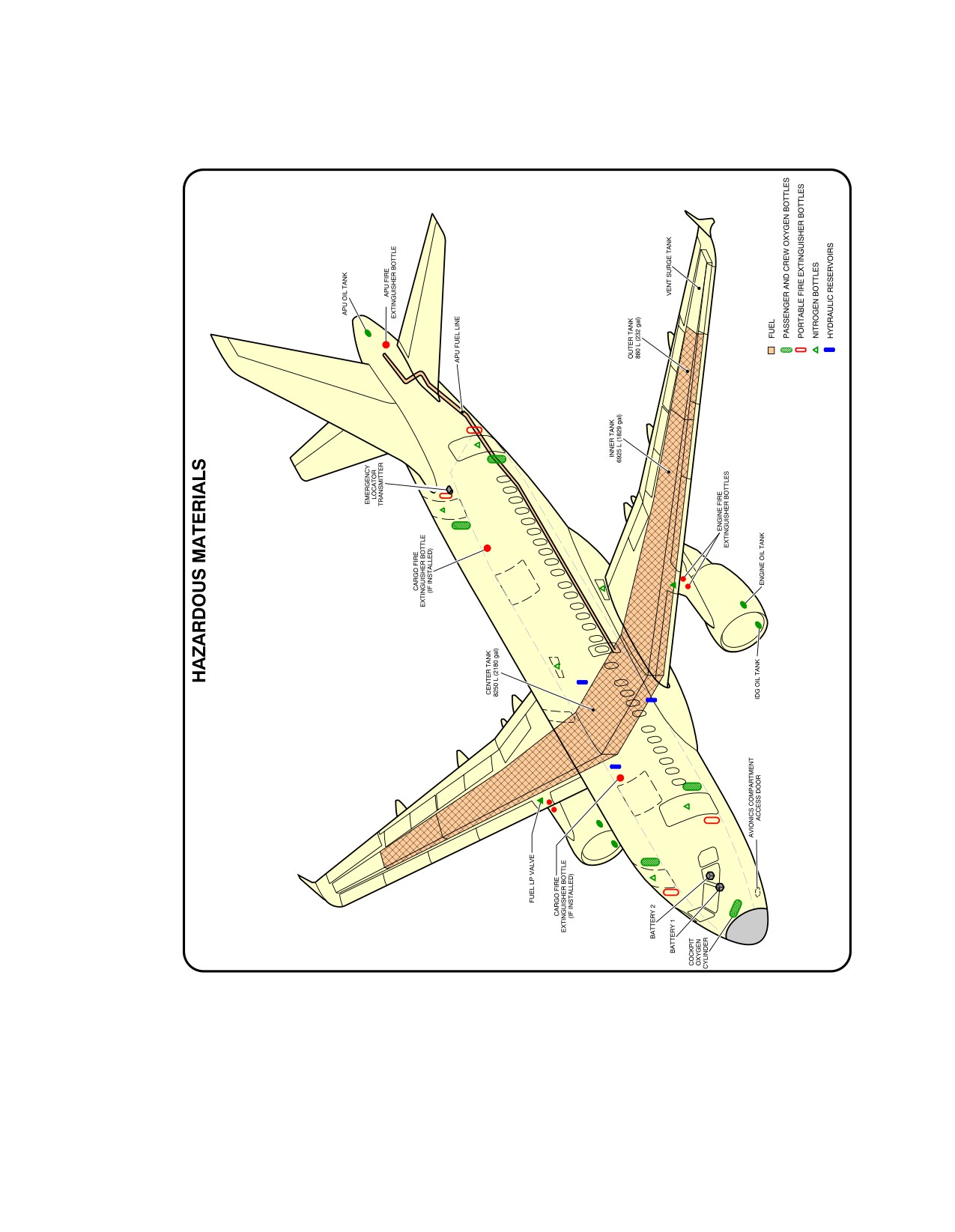
@A318
AIRCRAFT CHARACTERISTICS - AIRPORT AND MAINTENANCE PLANNING
**ON A/C A318-100
N_AC_100000_1_0020101_01_02
Highly Flammable and Hazardous Materials and Components
FIGURE-10-0-0-991-002-A01
Page 3
May 01/16
10-0-0
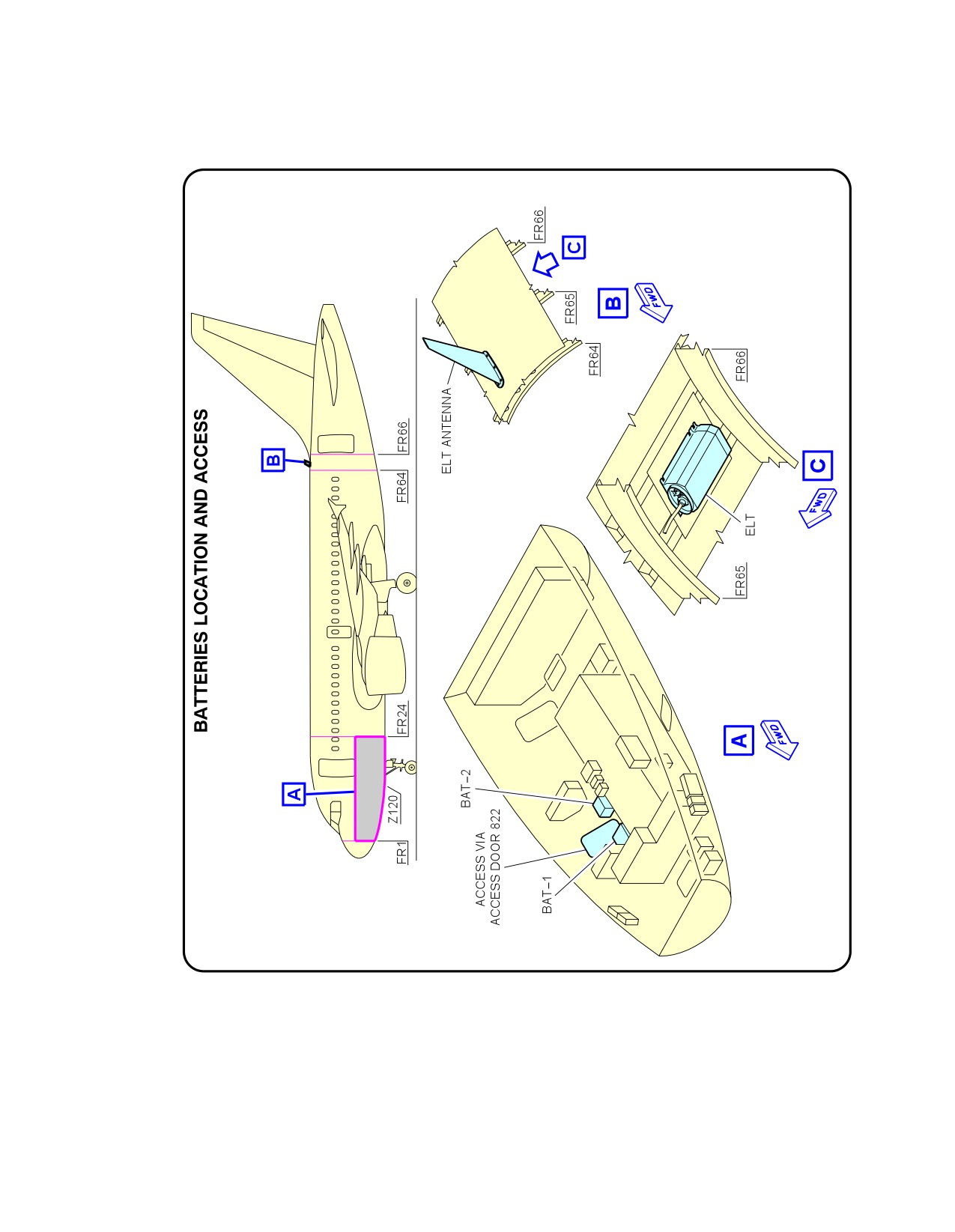
@A318
AIRCRAFT CHARACTERISTICS - AIRPORT AND MAINTENANCE PLANNING
**ON A/C A318-100
N_AC_100000_1_0550101_01_01
Batteries Location and Access
FIGURE-10-0-0-991-055-A01
Page 4
May 01/16
10-0-0
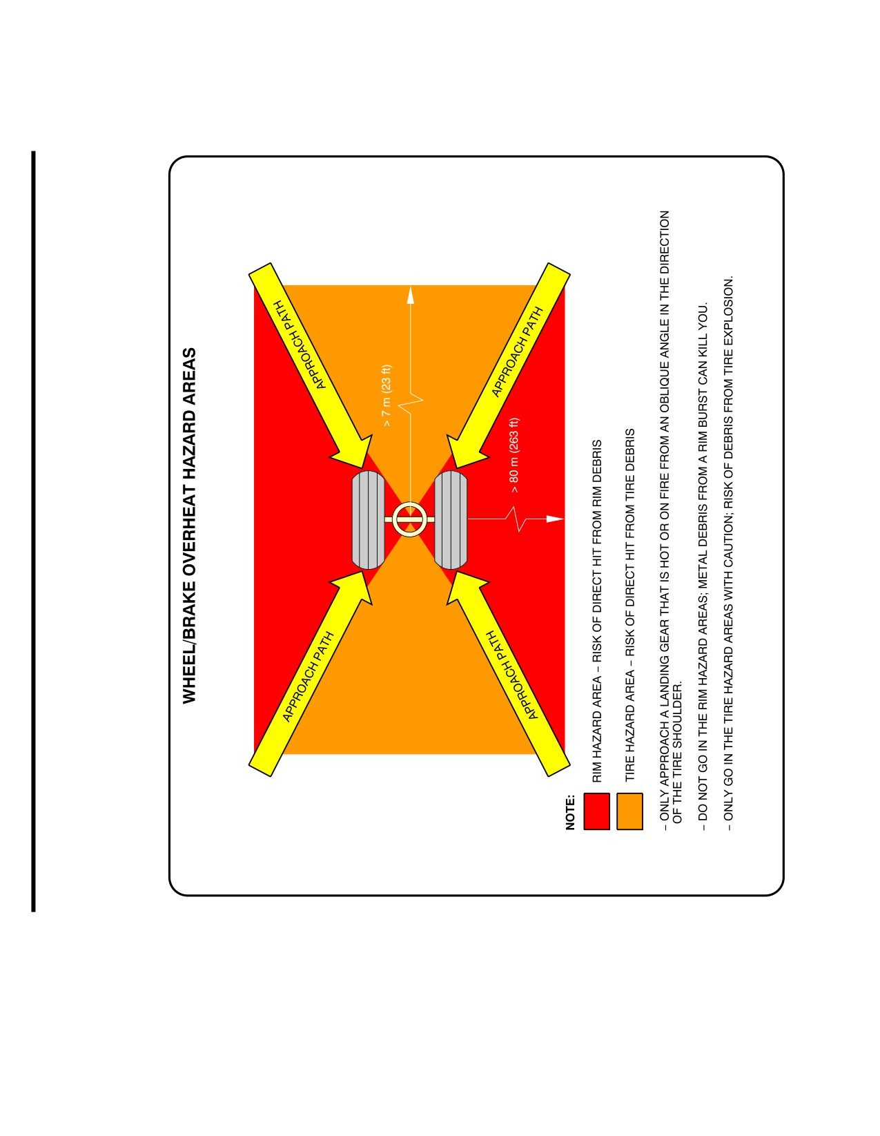
@A318
AIRCRAFT CHARACTERISTICS - AIRPORT AND MAINTENANCE PLANNING
**ON A/C A318-100
N_AC_100000_1_0030101_01_02
Wheel/Brake Overheat
Wheel Safety Area (Sheet 1 of 2)
FIGURE-10-0-0-991-003-A01
Page 5
May 01/16
10-0-0
@A318
AIRCRAFT CHARACTERISTICS - AIRPORT AND MAINTENANCE PLANNING
**ON A/C A318-100
N_AC_100000_1_0030102_01_00
Wheel/Brake Overheat
Recommendations (Sheet 2 of 2)
FIGURE-10-0-0-991-003-A01
Page 6
May 01/16
10-0-0
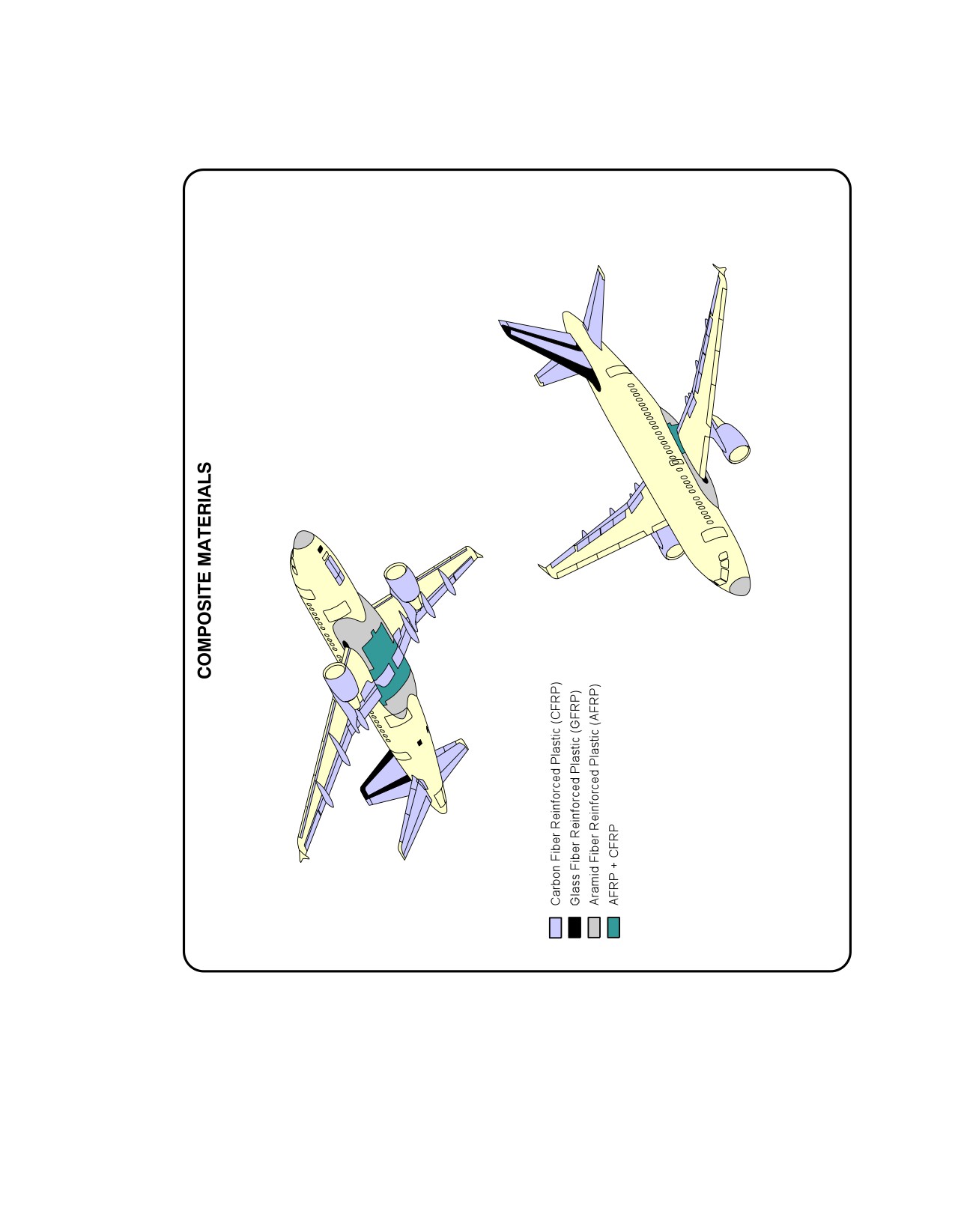
@A318
AIRCRAFT CHARACTERISTICS - AIRPORT AND MAINTENANCE PLANNING
**ON A/C A318-100
N_AC_100000_1_0040101_01_02
Composite Materials
FIGURE-10-0-0-991-004-A01
Page 7
May 01/16
10-0-0
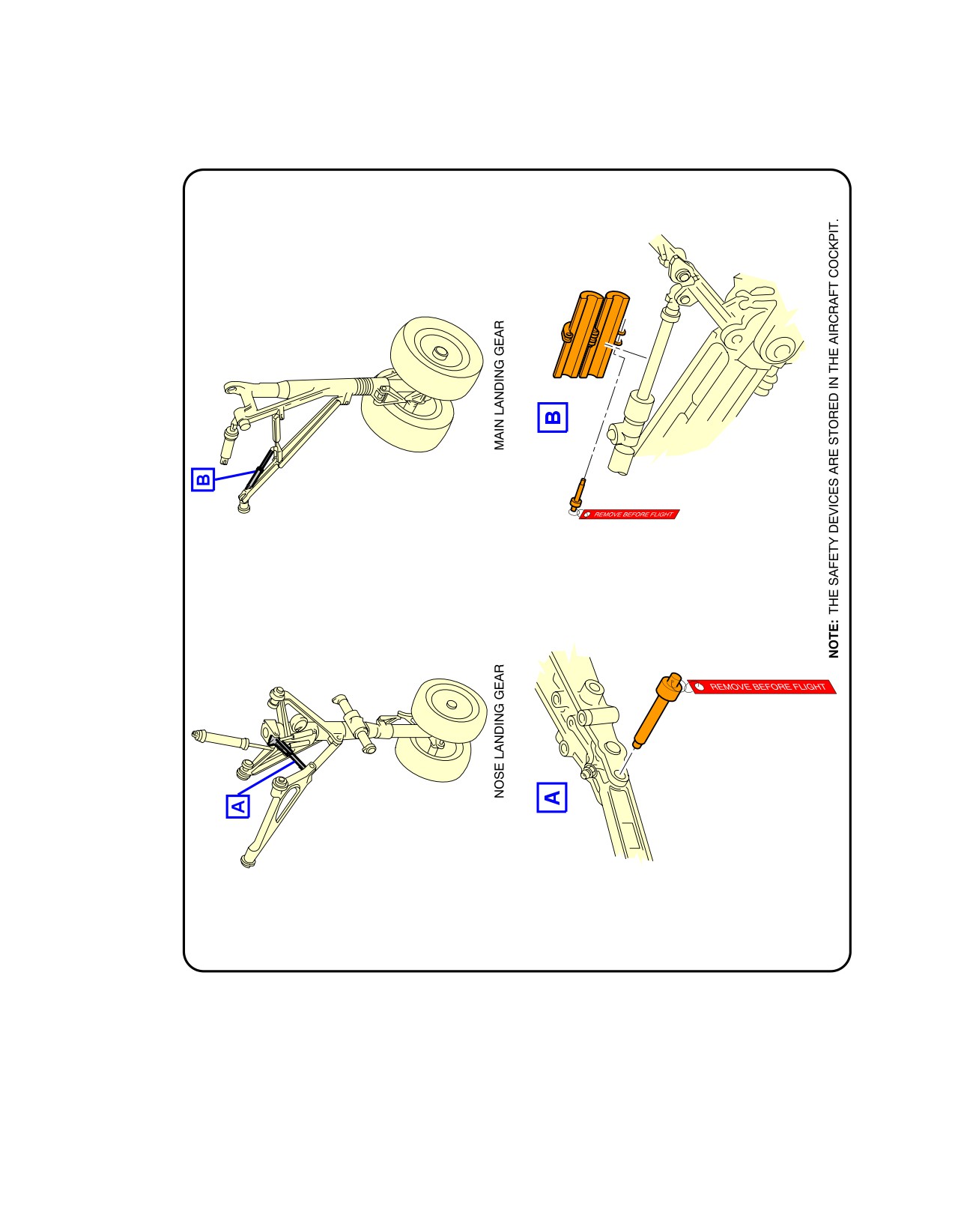
@A318
AIRCRAFT CHARACTERISTICS - AIRPORT AND MAINTENANCE PLANNING
**ON A/C A318-100
N_AC_100000_1_0050101_01_00
L/G Ground Lock Safety Devices
FIGURE-10-0-0-991-005-A01
Page 8
May 01/16
10-0-0
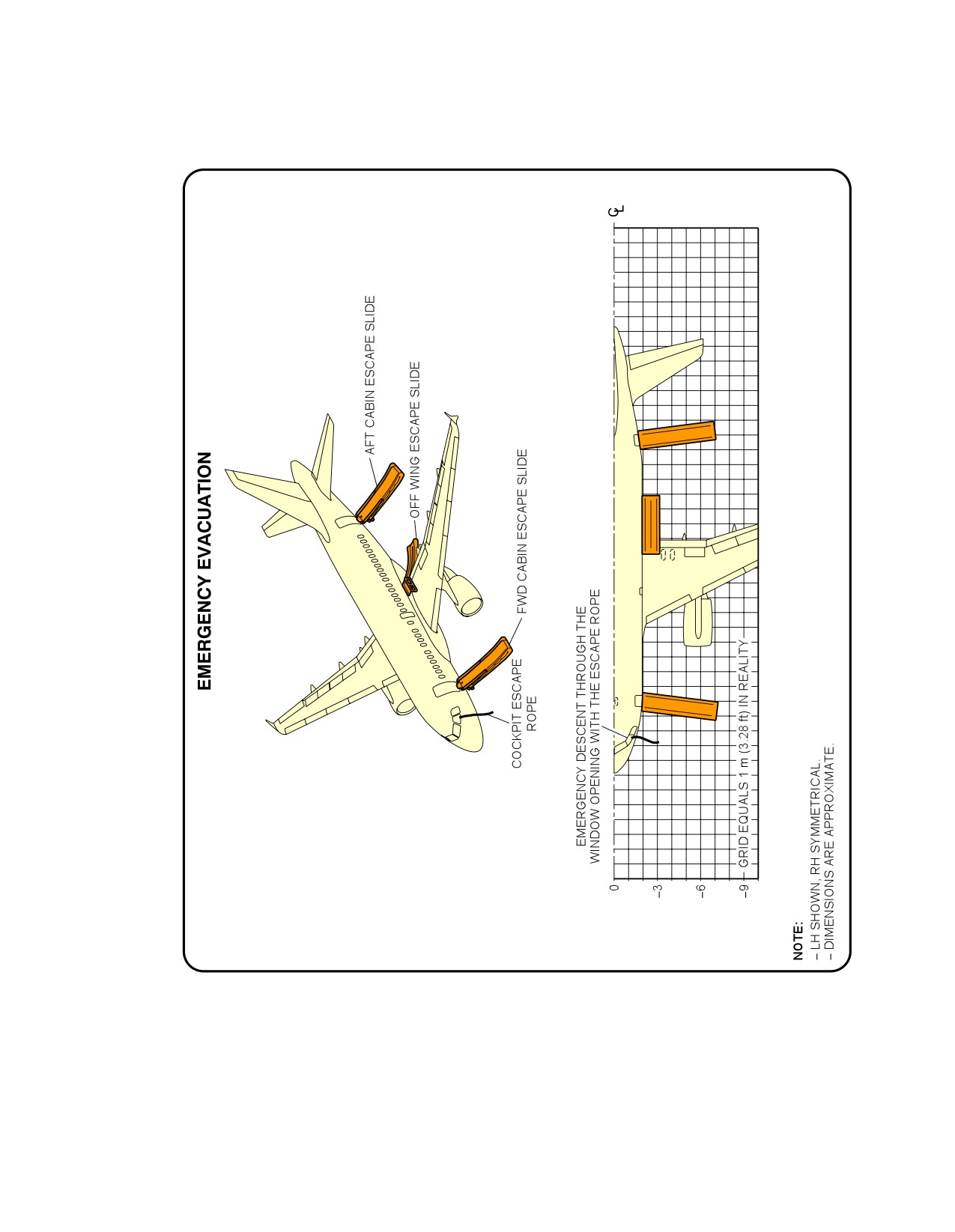
@A318
AIRCRAFT CHARACTERISTICS - AIRPORT AND MAINTENANCE PLANNING
**ON A/C A318-100
N_AC_100000_1_0060101_01_03
Emergency Evacuation Devices
FIGURE-10-0-0-991-006-A01
Page 9
May 01/16
10-0-0
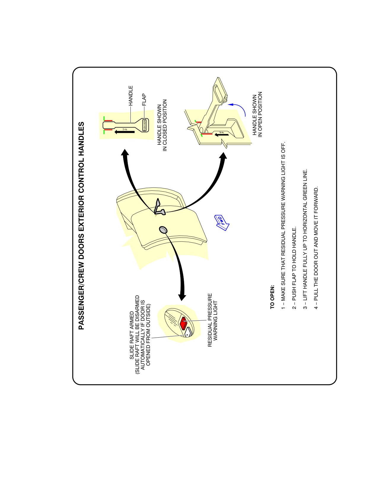
@A318
AIRCRAFT CHARACTERISTICS - AIRPORT AND MAINTENANCE PLANNING
**ON A/C A318-100
N_AC_100000_1_0070101_01_00
Pax/Crew Doors
FIGURE-10-0-0-991-007-A01
Page 10
May 01/16
10-0-0
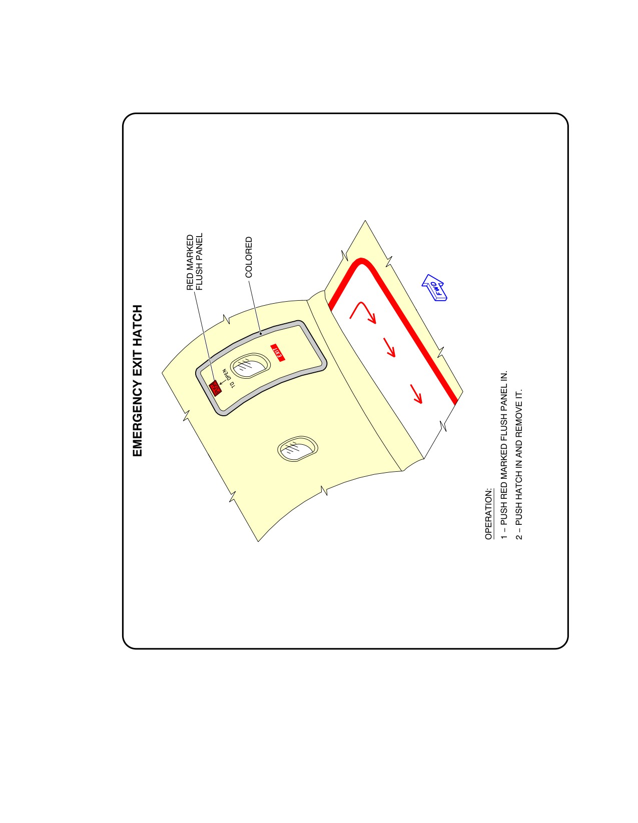
@A318
AIRCRAFT CHARACTERISTICS - AIRPORT AND MAINTENANCE PLANNING
**ON A/C A318-100
N_AC_100000_1_0080101_01_00
Emergency Exit Hatch
FIGURE-10-0-0-991-008-A01
Page 11
May 01/16
10-0-0
@A318
AIRCRAFT CHARACTERISTICS - AIRPORT AND MAINTENANCE PLANNING
**ON A/C A318-100
N_AC_100000_1_0090101_01_00
FWD and AFT Lower Deck Cargo Doors
FIGURE-10-0-0-991-009-A01
Page 12
May 01/16
10-0-0
@A318
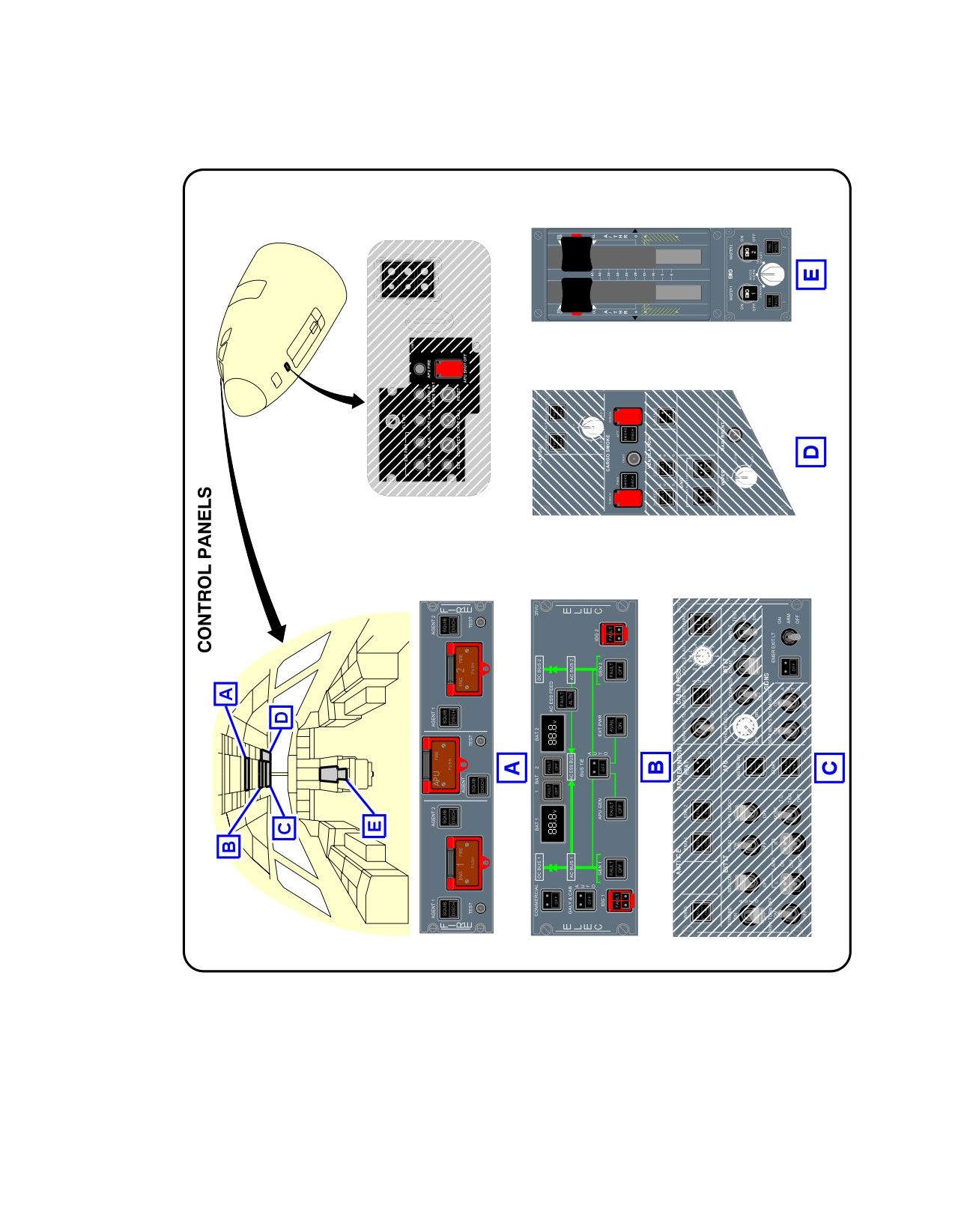
AIRCRAFT CHARACTERISTICS - AIRPORT AND MAINTENANCE PLANNING
**ON A/C A318-100
N_AC_100000_1_0120101_01_00
Control Panels
FIGURE-10-0-0-991-012-A01
Page 13
May 01/16
10-0-0
@A318
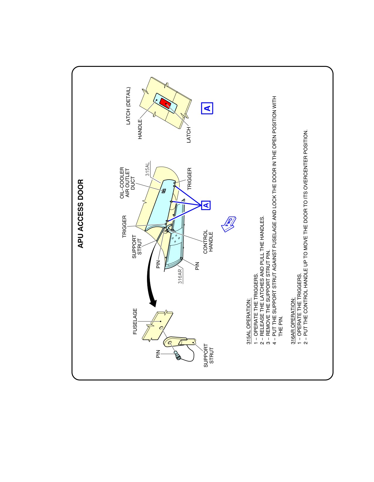
AIRCRAFT CHARACTERISTICS - AIRPORT AND MAINTENANCE PLANNING
**ON A/C A318-100
N_AC_100000_1_0130101_01_00
APU Access Door
FIGURE-10-0-0-991-013-A01
Page 14
May 01/16
10-0-0
@A318
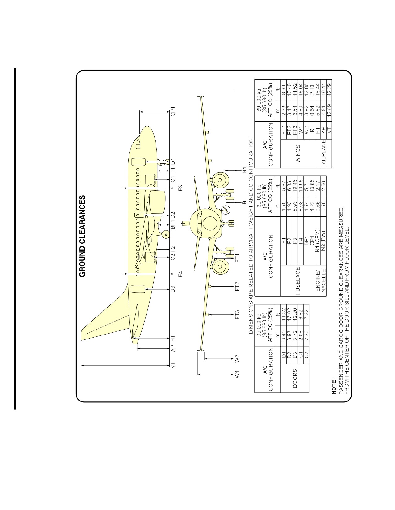
AIRCRAFT CHARACTERISTICS - AIRPORT AND MAINTENANCE PLANNING
**ON A/C A318-100
N_AC_100000_1_0140101_01_03
Aircraft Ground Clearances
FIGURE-10-0-0-991-014-A01
Page 15
May 01/16
10-0-0
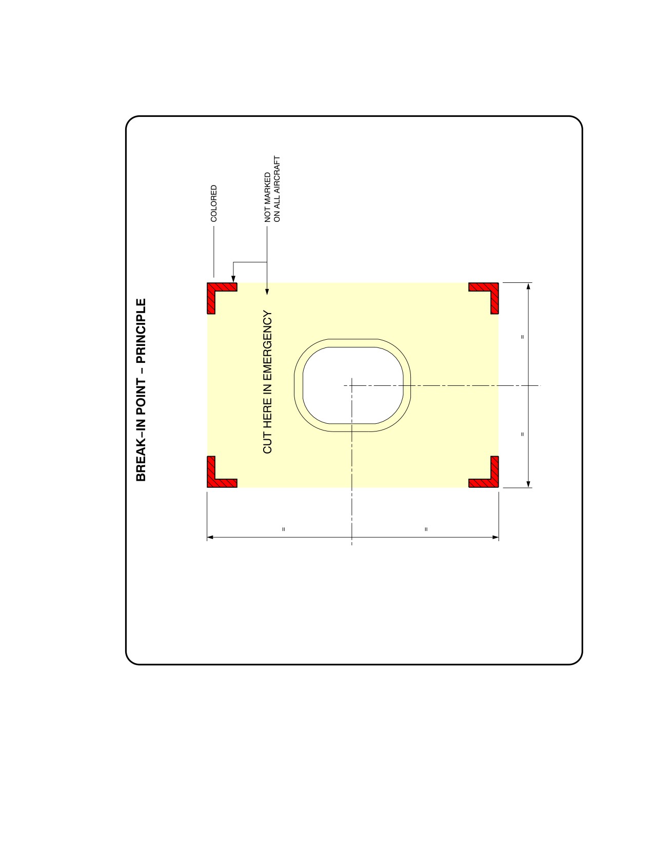
@A318
AIRCRAFT CHARACTERISTICS - AIRPORT AND MAINTENANCE PLANNING
**ON A/C A318-100
N_AC_100000_1_0150101_01_00
Structural Break-in Points
FIGURE-10-0-0-991-015-A01
Page 16
May 01/16
10-0-0