Airbus A330/A340. Flight Crew Training Manual (2007) - page 8
 

  Index      Manuals     Airbus A330/A340. Flight Crew Training Manual (2007)


Search            copyright infringement  


Content      ..     6      7      8      9     ..


Airbus A330/A340. Flight Crew Training Manual (2007) - page 8


FLIGHT CREW TRAINING MANUAL

NORMAL OPERATIONS

TAKEOFF

02.050

JAN 09/07

At take off, the typical all engine operating attitude after lift-off is about 15

˚

.

R

MSN 0002-0011 0013-0016 0018-0029 0031-0035 0038-0044 0046-0049 0051-0053 0056-0058

0061 0063 0074-0076 0078-0081 0084-0085 0088-0094 0097 0101 0103-0104 0114-0115 0117
0123-0126 0128-0131 0133-0137 0139 0141-0142 0145-0147 0149-0152 0154 0156-0161
0163-0164 0166-0170 0173-0176 0178-0180 0182 0185-0187 0190 0192-0194 0196-0197 0199
0201-0202 0204 0207-0208 0210 0212-0218 0220-0221 0225 0227-0228 0233 0235-0237
0239 0242-0243 0245-0246 0252 0257 0260 0263-0264 0268 0270 0273-0274 0278 0280
0282 0292 0297 0302 0304 0307 0310 0318-0319 0321 0325 0327 0329 0331-0332 0335
0347 0352 0354-0355 0359 0363 0367 0373-0374 0377-0379 0381 0385 0387 0390 0395
0399 0402 0406 0411 0413-0415 0424 0429-0430 0433-0435 0438 0442 0446-0447 0450
0459 0467 0470 0474 0483 0528 0538 0541 0544-0546 0554 0556 0559 0561-0562 0582
0585 0590 0598 0643 0646 0651 0668 0793 0800 0835 0844

At takeoff, the typical all engine operating attitude after lift-off is about 12.5

˚

.

ROTATION

R

MSN 0002-0860

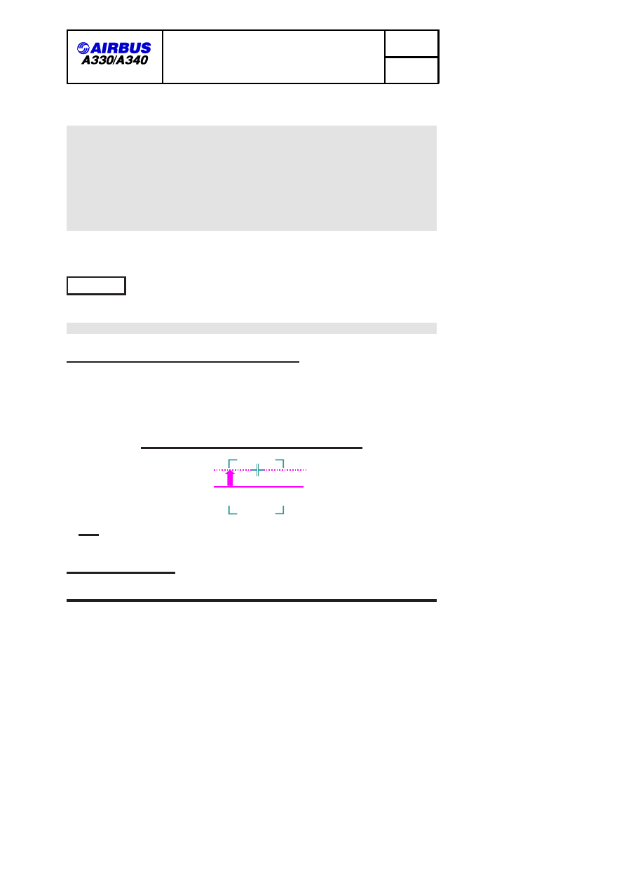
INITIAL STICK INPUT CALIBRATION IN TRAINING

In training, during taxi, the crew may calibrate the appropriate effort and
displacement for the initial stick input for rotation (2/3 back-stick), by pulling aft
on the stick and observing the position of the stick cross symbol on the PFD,
compared to the stick position reference square.

SIDE STICK INPUT CALIBRATION DURING TAXI

2/3

FOF 02050 03857 0001

Note: the cross is not to be used by PF during the takeoff, whereas the PNF

can check the validity of the PF initial stick input.

ROTATION TECHNIQUE

ENV A330/A340 FLEET FCTM

Page 5 of 23

FLIGHT CREW TRAINING MANUAL

NORMAL OPERATIONS

TAKEOFF

02.050

JAN 09/07

Rotation is conventional. During the takeoff roll and the rotation, the pilot flying
scans rapidly the outside visual reference and the PFD. Until airborne, or at least
until visual cues are lost, this scanning depends on visibility conditions (the better
the visibility, the higher the priority given to outside visual references). Once
airborne, the PF then controls the pitch attitude on the PFD using FD bars in
SRS mode which is then valid.

The higher the inertia of the aircraft is, the more it is important to initiate the
rotation with a smooth positive backward sidestick input (typically 2/3 backstick).
Avoid aggressive and sharp inputs.

The initial rotation rate takes time to establish. For a given sidestick input, once
it has developed, it remains relatively constant. It is typically between 2 and 3

˚

/sec.

If the established pitch rate is not satisfactory, the pilot must make smooth
corrections on the stick. He must avoid rapid and large corrections, which cause
sharp reaction in pitch from the aircraft. If, to increase the rotation rate, a further
and late aft sidestick input is made around the time of lift-off, the possibility of
tailstrike increases significantly.

During rotation, the crew must not chase the FD pitch bar, since it does not give
any pitch rate order, and might lead to overreaction.

Once airborne only, the crew must refine the aircraft pitch attitude using the FD,
which is then representative of the SRS orders. The fly-by-wire control laws
change into flight normal law, with automatic pitch trim active.

LONG AIRCRAFT SPECIFICITY

R

MSN 0371 0376 0383 0391 0394 0410 0416-0417 0426 0431 0436 0440 0445 0449 0453

0457 0460 0464 0468 0471 0475 0478 0482 0485 0488 0492 0495 0499 0514 0517 0520
0523 0531 0534 0537 0540 0543 0547 0557 0560 0563 0566 0569 0572 0575 0577 0580
0583 0586 0601 0604 0606 0608 0611 0615 0617 0619 0622 0624 0626 0628 0630 0639
0672 0677 0681 0685 0689 0694 0698 0702 0706 0710 0715 0719 0723 0727 0731 0736
0740 0744 0748 0753 0757 0761-0768 0771 0775 0779 0783 0787 0790 0794 0798 0804
0812 0829 0837 0846 0848

Compared to shorter aircraft, the sensory feedback to the pilot during the rotation
is different due to the length of the aircraft and its flexibility:

.

Since the aircraft is longer, for a same rotation rate, the local vertical

acceleration sensed by the pilot is higher.

VERTICAL ACCELERATION SENSING (1)

ENV A330/A340 FLEET FCTM

Page 6 of 23

FLIGHT CREW TRAINING MANUAL

NORMAL OPERATIONS

TAKEOFF

02.050

JAN 09/07

3°/sec.

FOF 02050 03864 0001

.

This effect is increased by the flexibility of the aircraft. The pilot senses first

(1), a delay in the rotation. Then (2), the sensory effects of the local vertical
acceleration are somehow amplified.

VERTICAL ACCELERATION SENSING (2)

2

1

FOF 02050 03865 0001

This sensory feedback shall not lead the pilot to overact by making large
changes in the sidestick inputs, which lead to potential large pitch oscillations. Be
smooth on the stick.

With respect to the rotation law of A330/ A340-300/-200, the A340-500/600, flight
control laws have been adapted to take into account the different characteristics
of the aircraft, such as longer fuselage. Additionally, rotation rate and
tail-clearance are monitored, and if tail-clearance becomes marginal the rotation
rate is automatically reduced until lift-off.

A pitch limit indication is provided on the PFD at takeoff. It is displayed from the
power application up to 3 seconds after lift off.

R

MSN 0181 0195 0205 0211 0222-0223 0226 0229-0230 0232 0238 0240 0247-0251

0253-0255 0258-0259 0261-0262 0265-0266 0269 0271-0272 0275-0276 0281 0283 0285-0291
0293-0296 0299-0301 0303 0305-0306 0308-0309 0311-0314 0316-0317 0320 0322 0324
0326 0328 0330 0334 0339-0340 0343 0345 0348 0353 0358 0361-0362 0364-0366 0369
0372 0382 0384 0392 0396-0398 0401 0403-0404 0409 0422 0427 0432 0437 0441
0443-0444 0448 0451-0452 0454-0456 0458 0461-0463 0465-0466 0469 0472-0473 0476-0477
0480-0481 0486-0487 0489 0491 0493-0494 0498 0500-0511 0513 0516 0518-0519 0521-0522
0525-0527 0529-0530 0532 0535-0536 0551 0555 0567 0571 0573 0584 0587 0597 0600
0605 0609-0610 0612-0614 0616 0618 0620-0621 0625 0627 0631-0635 0638 0644 0647
0649-0650 0652-0653 0655-0658 0660-0661 0664-0667 0678 0682-0684 0686 0688 0693
0696-0697 0700 0703-0704 0709 0717-0718 0722 0724 0726 0728-0730 0732-0733 0735
0737-0739 0742-0743 0745-0747 0749-0751 0754-0756 0759-0760 0770 0774 0778 0780
0785 0788 0792 0795-0797 0801-0802 0807-0811 0814-0815 0818-0822 0824-0825 0828
0831-0832 0834 0839-0842 0849 0852-0854 0860

ENV A330/A340 FLEET FCTM

Page 7 of 23

FLIGHT CREW TRAINING MANUAL

NORMAL OPERATIONS

TAKEOFF

02.050

JAN 09/07

AIRCRAFT GEOMETRY

MAX PITCH ATTITUDE ON GROUND depending on main gear

oleo position

fully extended

fully compressed

16.0

˚

11.5

˚

R

MSN 0030 0037 0045 0054-0055 0059 0070 0086 0183-0184 0188-0189 0191 0198 0200

0203 0553 0558 0564 0574 0593-0595 0602-0603 0607 0623 0637 0641 0659 0671 0675
0680 0691 0695 0699 0705 0707 0711-0712 0714 0721 0725 0734 0752 0769 0789 0805
0813 0823 0826 0838 0847

AIRCRAFT GEOMETRY

MAX PITCH ATTITUDE ON GROUND depending on main gear

oleo position

fully extended

fully compressed

14.2

˚

10.1

˚

R

MSN 0012 0017 0050 0060 0062 0064-0069 0071-0073 0077 0082-0083 0087 0095-0096

0098-0100 0102 0106-0113 0116 0118-0122 0127 0132 0138 0140 0143-0144 0148 0153
0155 0162 0165 0171-0172 0177 0206 0209 0219 0224 0231 0234 0241 0244 0256 0267
0277 0279 0284 0315 0323 0333 0337-0338 0342 0344 0346 0349-0351 0356-0357 0368
0370 0375 0380 0386 0388-0389 0393 0400 0405 0407-0408 0412 0418-0421 0423 0425
0428 0439 0479 0484 0490 0496-0497 0512 0515 0524 0533 0539 0542 0548-0550 0552
0565 0568 0570 0576 0578-0579 0581 0588 0591 0629 0636 0640 0642 0645 0648 0654
0662-0663 0669-0670 0673-0674 0676 0679 0687 0690 0692 0701 0708 0713 0716 0720
0741 0758 0772-0773 0776-0777 0781-0782 0784 0786 0791 0799 0803 0806 0817 0827
0830 0833 0836 0843 0845 0850-0851 0855-0859

AIRCRAFT GEOMETRY

MAX PITCH ATTITUDE ON GROUND depending on main gear

oleo position

fully extended

fully compressed

14.4

˚

10.1

˚

ENV A330/A340 FLEET FCTM

Page 8 of 23

FLIGHT CREW TRAINING MANUAL

NORMAL OPERATIONS

TAKEOFF

02.050

JAN 09/07

MSN 0004 0006 0008-0011 0014 0018-0019 0021-0022 0026 0031 0038 0043 0046 0061
0063 0074-0075 0080-0081 0085 0151 0156 0159 0178 0204

AIRCRAFT GEOMETRY

MAX PITCH ATTITUDE ON GROUND depending on main gear

oleo position

fully extended

fully compressed

15.8

˚

11.3

˚

R

MSN 0002-0003 0005 0007 0013 0015-0016 0020 0023-0025 0027-0029 0032-0035 0039-0041

0044 0047-0049 0051-0053 0056-0058 0076 0078-0079 0084 0088-0094 0097 0101 0103-0104
0114-0115 0117 0123-0126 0128-0131 0133-0137 0139 0141-0142 0145-0147 0149-0150 0152
0154 0157-0158 0160-0161 0163-0164 0166-0170 0173-0176 0179-0180 0182 0185-0187
0190 0192-0194 0196-0197 0199 0201-0202 0207-0208 0210 0212-0218 0220-0221 0225
0227-0228 0233 0235-0237 0239 0242-0243 0245-0246 0252 0257 0260 0263-0264 0268
0270 0273-0274 0278 0280 0282 0292 0297 0302 0304 0307 0310 0318-0319 0321 0325
0327 0329 0331-0332 0335 0347 0352 0354-0355 0359 0363 0367 0373-0374 0377-0379
0381 0385 0387 0390 0395 0399 0402 0406 0411 0413-0415 0424 0429-0430 0433-0435
0438 0442 0446-0447 0450 0459 0467 0470 0474 0483 0528 0538 0541 0544-0546 0554
0556 0559 0561-0562 0582 0585 0590 0598 0643 0646 0651 0668 0793 0800 0835 0844

AIRCRAFT GEOMETRY

MAX PITCH ATTITUDE ON GROUND depending on main gear

oleo position

fully extended

fully compressed

14.2

˚

10.1

˚

R

MSN 0394 0445 0457 0464 0471 0478 0485 0492 0495 0499 0520 0560 0563 0572 0608

0611 0624 0628 0685 0694 0698 0748 0757 0761 0775 0783

ENV A330/A340 FLEET FCTM

Page 9 of 23

FLIGHT CREW TRAINING MANUAL

NORMAL OPERATIONS

TAKEOFF

02.050

JAN 09/07

AIRCRAFT GEOMETRY

MAX PITCH ATTITUDE ON GROUND depending on main gear

oleo position

fully extended

fully compressed

13.5

˚

9.5

˚

R

MSN 0371 0376 0383 0391 0410 0416-0417 0426 0431 0436 0440 0449 0453 0460 0468

0475 0482 0488 0514 0517 0523 0531 0534 0537 0540 0543 0547 0557 0566 0569 0575
0577 0580 0583 0586 0601 0604 0606 0615 0617 0619 0622 0626 0630 0639 0672 0677
0681 0689 0702 0706 0710 0715 0719 0723 0727 0731 0736 0740 0744 0753 0762-0768
0771 0779 0787 0790 0794 0798 0804 0812 0829 0837 0846 0848

AIRCRAFT GEOMETRY

MAX PITCH ATTITUDE ON GROUND depending on main gear

oleo position

fully extended

fully compressed

12

˚

8.5

˚

TAIL STRIKE AVOIDANCE

R

MSN 0002-0860

INTRODUCTION

Tail strikes can cause extensive structural damage, which can jeopardize the
flight and lead to heavy maintenance action. They most often occur in such
adverse conditions as crosswind, turbulence, windshear, etc.

The minimum tail clearance occurs before lift off (due to rotating bogies).

MAIN FACTORS

EARLY ROTATION

ENV A330/A340 FLEET FCTM

Page 10 of 23

FLIGHT CREW TRAINING MANUAL

NORMAL OPERATIONS

TAKEOFF

02.050

JAN 09/07

Early rotation occurs when rotation is initiated below the scheduled VR. The
potential reasons for this are:

.

The calculated VR is incorrect for the aircraft weight or flap configuration.

.

The PF commands rotation below VR due to gusts, windshear or an obstacle

on the runway.

Whatever the cause of the early rotation, the result will be an increased pitch
attitude at lift-off, and consequently a reduced tail clearance.

ROTATION TECHNIQUE

The recommendation given in the ROTATION TECHNIQUE paragraph should be
applied.

A fast rotation rate increases the risk of tailstrike, but a slow rate increases
take-off distance. The recommended rate is between 2 and 3 degs/sec, which
reflects the average rates achieved during flight test, and is also the reference
rate for performance calculations.

CONFIGURATION

When performance is limiting the takeoff weight, the flight crew uses TOGA
thrust and selects the configuration that provides the highest takeoff weight.

When the actual takeoff weight is lower than the permissible one, the flight crew
uses FLEX TO thrust. For a given aircraft weight, a variety of flap configurations
are possible. Usually, the flight crew selects the configuration that provides the
maximum FLEX temperature. This is done to prolong engine life.

On A340-500/600:

For any runway length, CONF 3 usually provides the highest FLEX temperature,
and the tail clearance at lift off does not depends on the configuration. So, the
flight crew should select CONF 3.

On A330 and A340-300:

ENV A330/A340 FLEET FCTM

Page 11 of 23

FLIGHT CREW TRAINING MANUAL

NORMAL OPERATIONS

TAKEOFF

02.050

JAN 09/07

FOF 02050 00000 0001

In this area, CONF 3 provides

the highest FLX temperature.


The tail clearance does not

depend on the configuration.

Runway length

FLEX temp

In this area, CONF 3 is no longer the optimum

configuration in terms of FLX temperature.


The tail clearance depends on the configuration.

CONF 1+F

CONF 2

CONF 3

CONF 3

The configuration that provides the maximum FLEX temperature varies with the
runway length.

On short runways, CONF 3 usually provides the highest FLEX temperature, and
the tail clearance at lift off does not depends on the configuration. So, the flight
crew should select CONF 3.

On medium or long runways, the second segment limitation becomes the limiting
factor, and CONF 2 or CONF 1+F becomes the optimum configuration, in term
of FLEX temperature. In these cases, the tail clearance at lift off depends on the
configuration. The highest flap configuration gives the highest tailstrike margin.

There is a difference between twin and quadri, regarding this concern: The A330
has more tail clearance than the A340, that has quite often, takeoff speeds
closer to VMU limitation. This is true with one engine inoperative. Since twin
aircraft have more thrust margin for takeoff, this is even more the case with all
engines operative.

On A340-300, selecting CONF 3 instead of 1+F increases the tail clearance by
1.5 to 2ft, at the expense of a loss in FLEX temperature generally less than 3

˚

C.

Note: detailed effect:

..

From CONF 1+F to CONF 2: Tail clearance increased by 0.5 to 1 ft,

loss in FLEX temperature generally less than 1

˚

C.

ENV A330/A340 FLEET FCTM

Page 12 of 23

FLIGHT CREW TRAINING MANUAL

NORMAL OPERATIONS

TAKEOFF

02.050

JAN 09/07

.

From CONF 2 to CONF 3: Tail clearance increased by 1 ft, loss in

FLEX temperature generally less than 2

˚

C.

The first degrees of flexible thrust have an impact on maintenance costs about 5
times higher than the last one.

Summary:

On A340-200/300, taking the above into consideration, the crew may decide to
select CONF 2 or CONF 3:

.

When the FLEX temperature is close to Tref, it is advisable to select one

more step of flaps (compared to the optimum one).

.

When the FLEX temperature is more than 15

˚

C above Tref, it is advisable to

select CONF 3.

TAKEOFF TRIM SETTING

The main purpose of the pitch trim setting for take-off is to provide consistent
rotation characteristics. Takeoff pitch trim setting is automatic on ground on the
340-500/600 and A330/A340 Enhanced (with specific aircraft definition) and is set
manually via the pitch trim wheel on other A330/340 models.

The aircraft performs a safe takeoff, provided the pitch trim setting is within the
green band on the pitch trim wheel.

However, the pitch trim setting significantly affects the aircraft behaviour during
rotation:

.

With a forward CG and the pitch trim set to the nose-down limit the pilots will

feel an aircraft heavy to rotate" and aircraft rotation will be very slow in
response to the normal take off stick displacement.

.

With an aft CG and the pitch trim set to the nose-up limit the pilots will most

probably have to counteract an early autorotation until VR is reached.

In either case the pilot may have to modify his normal control input in order to
achieve the desired rotation rate, but should be cautious not to overreact.

CROSSWIND TAKEOFF

It is said in the TAKEOFF ROLL paragraph that care should be taken to avoid
using large deflection, resulting in excessive spoiler deployment.

A direct effect of the reduction in lift due to the extension of the spoilers on one
wing will be a reduction in tail clearance and an increased risk of tailstrike.

OLEO INFLATION

ENV A330/A340 FLEET FCTM

Page 13 of 23

FLIGHT CREW TRAINING MANUAL

NORMAL OPERATIONS

TAKEOFF

02.050

JAN 09/07

The correct extension of the main landing gear shock absorber (and thus the
nominal increase in tail clearance during the rotation) relies on the correct
inflation of the oleos. An under inflated oleo will delay the start of the bogie
rotation and reduce tail clearances.

ACTION IN CASE OF TAILSTRIKE

If a tailstrike occurs at takeoff, flight at attitude requiring a pressurized cabin
must be avoided and a return to the originating airport should be performed for
damage assessment.

R

MSN 0030 0037 0045 0050 0054-0055 0059-0060 0062 0064-0070 0072-0073 0077 0082

0086-0087 0095-0096 0100 0107 0110 0112 0116 0119-0120 0122 0127 0143 0162
0171-0172 0181 0183-0184 0188-0189 0191 0195 0198 0200 0203 0205-0206 0209 0211
0219 0222-0224 0226 0229-0232 0238 0240-0241 0247 0249 0253 0255-0256 0258-0259
0262 0267 0269 0272 0275 0288-0291 0294 0296 0299-0300 0305 0308 0312 0315 0317
0322-0324 0330 0333 0337-0339 0342-0343 0346 0350-0351 0353 0358 0361-0362 0364
0366 0368 0370 0375 0380 0388 0397 0403 0422 0425 0428 0432 0441 0443-0444 0448
0454 0458 0463 0465-0466 0469 0472-0473 0476-0477 0481 0484 0486-0487 0489-0490
0493 0498 0500 0502-0504 0506-0508 0510-0511 0513 0516 0519 0521-0522 0524 0530
0533 0535 0542 0549-0550 0552-0553 0555 0558 0564 0567 0571 0573-0574 0578 0584
0587-0588 0591-0595 0602-0603 0605 0607 0609 0612-0614 0616 0618 0620-0621 0623
0631 0633-0634 0637-0638 0640-0641 0644 0647 0650 0653 0655 0657 0659-0661 0663
0665 0667 0671 0674-0676 0678 0680 0682 0684 0686 0690-0691 0693 0695 0697
0699-0700 0703-0705 0707-0708 0711-0712 0714 0718 0721-0722 0725 0733-0734 0738-0739
0742-0743 0745-0747 0749 0752 0754-0755 0758 0760 0769-0770 0772 0774 0778 0784
0789 0792 0796 0799 0801-0803 0805-0806 0811 0813-0814 0817 0819-0820 0822-0823
0825-0828 0831 0834 0838 0841-0843 0845 0847 0849 0853 0857-0859

MAXIMUM DEMONSTRATED CROSSWIND FOR TAKE-OFF

Reported Braking

Action

Reported Runway

Friction

Coefficient

Maximum

demonstrated

Crosswind for

takeoff (kt)

Equivalent

Runway

Condition

Good*

0.4

32

Dry, damp, wet (<
3mm)

ENV A330/A340 FLEET FCTM

Page 14 of 23

FLIGHT CREW TRAINING MANUAL

NORMAL OPERATIONS

TAKEOFF

02.050

JAN 09/07

R

MSN 0002-0011 0013-0016 0018-0029 0031-0035 0038-0044 0046-0049 0051-0053 0056-0058

0061 0063 0074-0076 0078-0081 0084-0085 0088-0094 0097 0101 0103-0104 0114-0115 0117
0123-0126 0128-0131 0133-0137 0139 0141-0142 0145-0147 0149-0152 0154 0156-0161
0163-0164 0166-0170 0173-0176 0178-0180 0182 0185-0187 0190 0192-0194 0196-0197 0199
0201-0202 0204 0207-0208 0210 0212-0218 0220-0221 0225 0227-0228 0233 0235-0237
0239 0242-0243 0245-0246 0252 0257 0260 0263-0264 0268 0270 0273-0274 0278 0280
0282 0292 0297 0302 0304 0307 0310 0318-0319 0321 0325 0327 0329 0331-0332 0335
0347 0352 0354-0355 0359 0363 0367 0373-0374 0377-0379 0381 0385 0387 0390 0395
0399 0402 0406 0411 0413-0415 0424 0429-0430 0433-0435 0438 0442 0446-0447 0450
0459 0467 0470 0474 0483 0528 0538 0541 0544-0546 0554 0556 0559 0561-0562 0582
0585 0590 0598 0643 0646 0651 0668 0793 0800 0835 0844

MAXIMUM DEMONSTRATED CROSSWIND FOR TAKE-OFF

Reported Braking

Action

Reported Runway

Friction

Coefficient

Maximum

Demonstrated

Crosswind for

takeoff (kt)

Equivalent

Runway

Condition

Good*

0.4

27

Dry, damp, wet (<
3mm)

MAXIMUM CERTIFIED CROSSWIND FOR TAKEOFF

R

MSN 0371 0376 0383 0391 0394 0410 0416-0417 0426 0431 0436 0440 0445 0449 0453

0457 0460 0464 0468 0471 0475 0478 0482 0485 0488 0492 0495 0499 0514 0517 0520
0523 0531 0534 0537 0540 0543 0547 0557 0560 0563 0566 0569 0572 0575 0577 0580
0583 0586 0601 0604 0606 0608 0611 0615 0617 0619 0622 0624 0626 0628 0630 0639
0672 0677 0681 0685 0689 0694 0698 0702 0706 0710 0715 0719 0723 0727 0731 0736
0740 0744 0748 0753 0757 0761-0768 0771 0775 0779 0783 0787 0790 0794 0798 0804
0812 0829 0837 0846 0848

Reported Braking

Action

Reported Runway

Friction

Coefficient

Maximum

certified

Crosswind for

takeoff (kt)

Equivalent

Runway

Condition

Good*

0.4

35

Dry, damp, wet (<
3mm)

ENV A330/A340 FLEET FCTM

Page 15 of 23

FLIGHT CREW TRAINING MANUAL

NORMAL OPERATIONS

TAKEOFF

02.050

JAN 09/07

R

MSN 0012 0017 0071 0083 0098-0099 0102 0106 0109 0111 0113 0118 0121 0132 0138

0140 0144 0148 0153 0155 0165 0177 0234 0244 0248 0250-0251 0254 0261 0265-0266
0271 0276-0277 0279 0281 0283-0287 0293 0295 0301 0303 0306 0309 0311 0313-0314
0316 0320 0326 0328 0334 0340 0344-0345 0348-0349 0356-0357 0365 0369 0372 0382
0384 0386 0389 0392-0393 0396 0398 0400-0401 0404-0405 0407-0409 0412 0418-0421 0423
0427 0437 0439 0451-0452 0455-0456 0461-0462 0479-0480 0491 0494 0496-0497 0501
0505 0509 0512 0515 0518 0525-0527 0529 0532 0536 0539 0548 0551 0565 0568 0570
0576 0579 0581 0597 0600 0610 0625 0627 0629 0632 0635-0636 0642 0645 0648-0649
0652 0654 0656 0658 0662 0664 0666 0669-0670 0673 0679 0683 0687-0688 0692 0696
0701 0709 0713 0716-0717 0720 0724 0726 0728-0730 0732 0735 0737 0741 0750-0751
0756 0759 0773 0776-0777 0780-0782 0785-0786 0788 0791 0795 0797 0807-0810 0815
0818 0821 0824 0830 0832-0833 0836 0839-0840 0850-0852 0854-0855 0860

Reported Braking

Action

Reported Runway

Friction

Coefficient

Maximum

certified

Crosswind for

takeoff (kt)

Equivalent

Runway

Condition

Good*

0.4

32

Dry, damp, wet (<
3mm)

AP ENGAGEMENT

R

MSN 0002-0860

The AP can be engaged 5 seconds after takeoff and above 100ft RA.

VERTICAL PROFILE

ENV A330/A340 FLEET FCTM

Page 16 of 23

FLIGHT CREW TRAINING MANUAL

NORMAL OPERATIONS

TAKEOFF

02.050

JAN 09/07

R

MSN 0012 0017 0030 0037 0045 0050 0054-0055 0059-0060 0062 0064-0073 0077

0082-0083 0086-0087 0095-0096 0098-0100 0102 0106-0113 0116 0118-0122 0127 0132 0138
0140 0143-0144 0148 0153 0155 0162 0165 0171-0172 0177 0181 0183-0184 0188-0189
0191 0195 0198 0200 0203 0205-0206 0209 0211 0219 0222-0224 0226 0229-0232 0234
0238 0240-0241 0244 0247-0251 0253-0256 0258-0259 0261-0262 0265-0267 0269 0271-0272
0275-0277 0279 0281 0283-0291 0293-0296 0299-0301 0303 0305-0306 0308-0309 0311-0317
0320 0322-0324 0326 0328 0330 0333-0334 0337-0346 0348-0351 0353 0356-0358 0361-0362
0364-0366 0368-0370 0372 0375 0380 0382 0384 0386 0388-0389 0392-0393 0396-0398
0400-0401 0403-0405 0407-0409 0412 0418-0423 0425 0427-0428 0432 0437 0439 0441
0443-0444 0448 0451-0452 0454-0456 0458 0461-0463 0465-0466 0469 0472-0473 0476-0477
0479-0481 0484 0486-0487 0489-0491 0493-0494 0496-0498 0500-0513 0515-0516 0518-0519
0521-0522 0524-0527 0529-0530 0532-0533 0535-0536 0539 0542 0548-0553 0555 0558
0564-0565 0567-0568 0570-0571 0573-0574 0576 0578-0579 0581 0584 0587-0588 0591-0597
0600 0602-0603 0605 0607 0609-0610 0612-0614 0616 0618 0620-0621 0623 0625 0627
0629 0631-0638 0640-0642 0644-0645 0647-0650 0652-0667 0669-0671 0673-0676 0678-0680
0682-0684 0686-0688 0690-0693 0695-0697 0699-0701 0703-0705 0707-0709 0711-0714
0716-0718 0720-0722 0724-0726 0728-0730 0732-0735 0737-0739 0741-0743 0745-0747
0749-0752 0754-0756 0758-0760 0769-0770 0772-0774 0776-0778 0780-0782 0784-0786
0788-0789 0791-0792 0795-0797 0799 0801-0803 0805-0811 0813-0828 0830-0834 0836
0838-0843 0845 0847 0849-0860

SRS engages when the thrust levers are set to the applicable detent for take-off
and will remain engaged until the acceleration altitude. The SRS pitch command
is the minimum of the following pitches:

.

Pitch required to fly V2 +10 in All Engine Operative case (AEO)

.

Pitch required to fly IAS at the time of failure (with minimum of V2 and

maximum of V2+15) in One Engine Inoperative case (OEI)

.

Pitch required to climb a 0.5

˚

minimum climb gradient.

.

Maximum pitch attitude of 17.5

˚

(22.5

˚

in case of windshear)

This explains why, in many take-off, the IAS which is actually flown is neither
V2+10 (AEO) nor V2 (OEI).

ENV A330/A340 FLEET FCTM

Page 17 of 23

FLIGHT CREW TRAINING MANUAL

NORMAL OPERATIONS

TAKEOFF

02.050

JAN 09/07

R

MSN 0002-0011 0013-0016 0018-0029 0031-0035 0038-0044 0046-0049 0051-0053 0056-0058

0061 0063 0074-0076 0078-0081 0084-0085 0088-0094 0097 0101 0103-0104 0114-0115 0117
0123-0126 0128-0131 0133-0137 0139 0141-0142 0145-0147 0149-0152 0154 0156-0161
0163-0164 0166-0170 0173-0176 0178-0180 0182 0185-0187 0190 0192-0194 0196-0197 0199
0201-0202 0204 0207-0208 0210 0212-0218 0220-0221 0225 0227-0228 0233 0235-0237
0239 0242-0243 0245-0246 0252 0257 0260 0263-0264 0268 0270 0273-0274 0278 0280
0282 0292 0297 0302 0304 0307 0310 0318-0319 0321 0325 0327 0329 0331-0332
0335 0347 0352 0354-0355 0359 0363 0367 0371 0373-0374 0376-0379 0381 0383 0385
0387 0390-0391 0394-0395 0399 0402 0406 0410-0411 0413-0417 0424 0426 0429-0431
0433-0436 0438 0440 0442 0445-0447 0449-0450 0453 0457 0459-0460 0464 0467-0468
0470-0471 0474-0475 0478 0482-0483 0485 0488 0492 0495 0499 0514 0517 0520 0523
0528 0531 0534 0537-0538 0540-0541 0543-0547 0554 0556-0557 0559-0563 0566 0569
0572 0575 0577 0580 0582-0583 0585-0586 0590 0598 0601 0604 0606 0608 0611 0615
0617 0619 0622 0624 0626 0628 0630 0639 0643 0646 0651 0668 0672 0677 0681 0685
0689 0694 0698 0702 0706 0710 0715 0719 0723 0727 0731 0736 0740 0744 0748 0753
0757 0761-0768 0771 0775 0779 0783 0787 0790 0793-0794 0798 0800 0804 0812 0829
0835 0837 0844 0846 0848

SRS engages when the thrust levers are set to the applicable detent for take-off
and will remain engaged until the acceleration altitude. The SRS pitch command
is the minimum of the following pitches:

-- Pitch required to fly V2 +10 in All Engine Operative case (AEO)

-- Pitch required to fly IAS at the time of failure (with minimum of V2 and

maximum of V2+15) in One Engine Inoperative case (OEI)

-- Maximum pitch attitude of 15

˚

(22.5

˚

in case of windshear)

-- Pitch required to climb a 0.5

˚

minimum climb gradient.

This explains why, in many take-off, the IAS which is actually flown is neither
V2+10 (AEO) nor V2 (OEI).

LATERAL PROFILE

R

MSN 0002-0860

Under most circumstances, the crew can expect to follow the programmed SID.
In this case, NAV is armed on selecting the thrust levers to the applicable detent
for take-off and engages once above 30 ft RA.

THRUST REDUCTION ALTITUDE

ENV A330/A340 FLEET FCTM

Page 18 of 23

FLIGHT CREW TRAINING MANUAL

NORMAL OPERATIONS

TAKEOFF

02.050

JAN 09/07

R

MSN 0002-0860

At the thrust reduction altitude, LVR CLB" flashes on the FMA.

When hand

flying, lower slightly the nose, as applicable, to anticipate the pitch down FD
order. Bring the thrust levers back to CLB detent. The A/THR is now active
(A/THR on the FMA changes from blue to white).

The FD pitch down order depends upon the amount of thrust decrease between
TOGA or FLX and CLB.

If take-off was performed packs OFF, the packs will be selected back to ON
after thrust reduction because of the potential resulting EGT increase. They will
be preferably selected sequentially to improve passengers comfort.

ACCELERATION ALTITUDE

R

MSN 0002-0860

At the acceleration altitude, the FD pitch mode changes from SRS to CLB or OP
CLB mode. The speed target jumps:

.

Either to the managed target speed (eg; speed constraint, speed limit or

ECON climb speed),

.

Or to the preselected climb speed (entered by the pilot on PERF CLB page

before takeoff).

If green dot speed is higher than the managed target speed (eg: 250 kt speed
limit) displayed by a magenta triangle on the PFD speed scale, the AP/FD will
guide the aircraft to green dot (as per the general managed speed guidance
rule). If required by ATC, the crew will select the adequate target speed (below
green dot) on the FCU.

During takeoff phase, F and S speeds are the minimum speeds for retracting the
surfaces:

.

At F speed, the aircraft accelerating (positive speed trend): retract to 1.

.

At S speed, the aircraft accelerating (positive speed trend): retract to 0.

If the engine start selector had been selected to IGN START for take-off, the
PNF should confirm with the PF when it may be deselected.

ENV A330/A340 FLEET FCTM

Page 19 of 23

FLIGHT CREW TRAINING MANUAL

NORMAL OPERATIONS

TAKEOFF

02.050

JAN 09/07

TAKE-OFF AT HEAVY WEIGHT

R

MSN 0002-0860

R (1)

If take-off is carried out at heavy weight, the maneuvring speed F may be close
to VFEConf 2 and S speed is above VFE Conf1+F. In this case, three
protections intervene:

.

The Flap Load Relief System (FLRS)

.

The Automatic Retraction System (ARS)

.

The alpha Lock function

R (2)

THE FLAP LOAD RELIEF SYSTEM

When IAS reaches VFE, the FLRS is activated. It retracts automatically the flaps
to the next further retracted lever position. Typically, this may occur in CONF 2,
when F speed is close to VFECONF2. In this case, VFE is unchanged on PFD
speed scale. (Displayed VFE remains VFE Conf 2 in accordance with the flap
lever position). "RELIEF" is displayed on the E/WD Flap/Slat indication. As the
aircraft accelerates above F speed, the flap lever can be selected to 1. If IAS
decreases below VFE, the flaps will re-extend.

R (3)

THE AUTOMATIC RETRACTION SYSTEM

While in Conf 1+F and IAS reaches 200 kts (215 kts for the A340-500 or -600),
the ARS is activated. The ARS automatically retracts flaps to 0

˚

. The VFE

displayed on the PFD change from VFE CONF1+F to VFECONF As the aircraft
accelerates above S speed, the flap lever can be selected to 0. If IAS decreases
below 200 kts (215 kts for the A340-500 or -600), the flaps will not extend back
to 1+F.

THE LPHA LOCK FUNCTION

The slats alpha/speed lock function will prevent slat retraction at high AOA or
low speed at the moment the flap lever is moved from Flaps 1 to Flaps 0. "A.
LOCK" pulses above the E/WD Slat indication. The inhibition is removed and the
slats retract when both alpha and speed fall within normal values. This is a

ENV A330/A340 FLEET FCTM

Page 20 of 23


Content      ..     6      7      8      9     ..