NATOPS FLIGHT MANUAL NAVY MODEL AV--8B/TAV--8B 161573 AND UP AIRCRAFT (2008) - page 2
A1-AV8BB--NFM--000
CHAPTER 1
Aircraft and Engine
1.1
AIRCRAFT DESCRIPTION
1.1.1 Day Attack
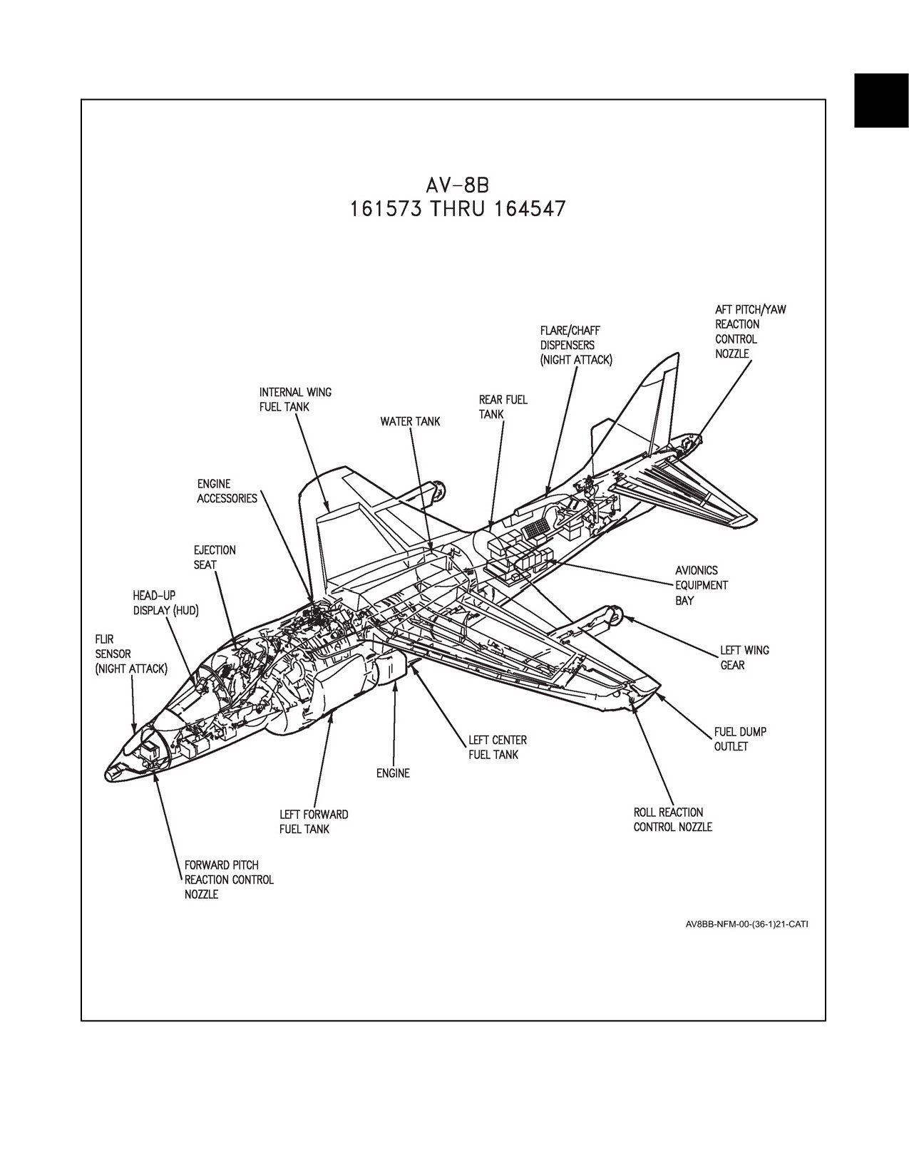
The AV--8B day attack aircraft is a transonic, single cockpit, single engine, jet propelled day/night tactical fighter
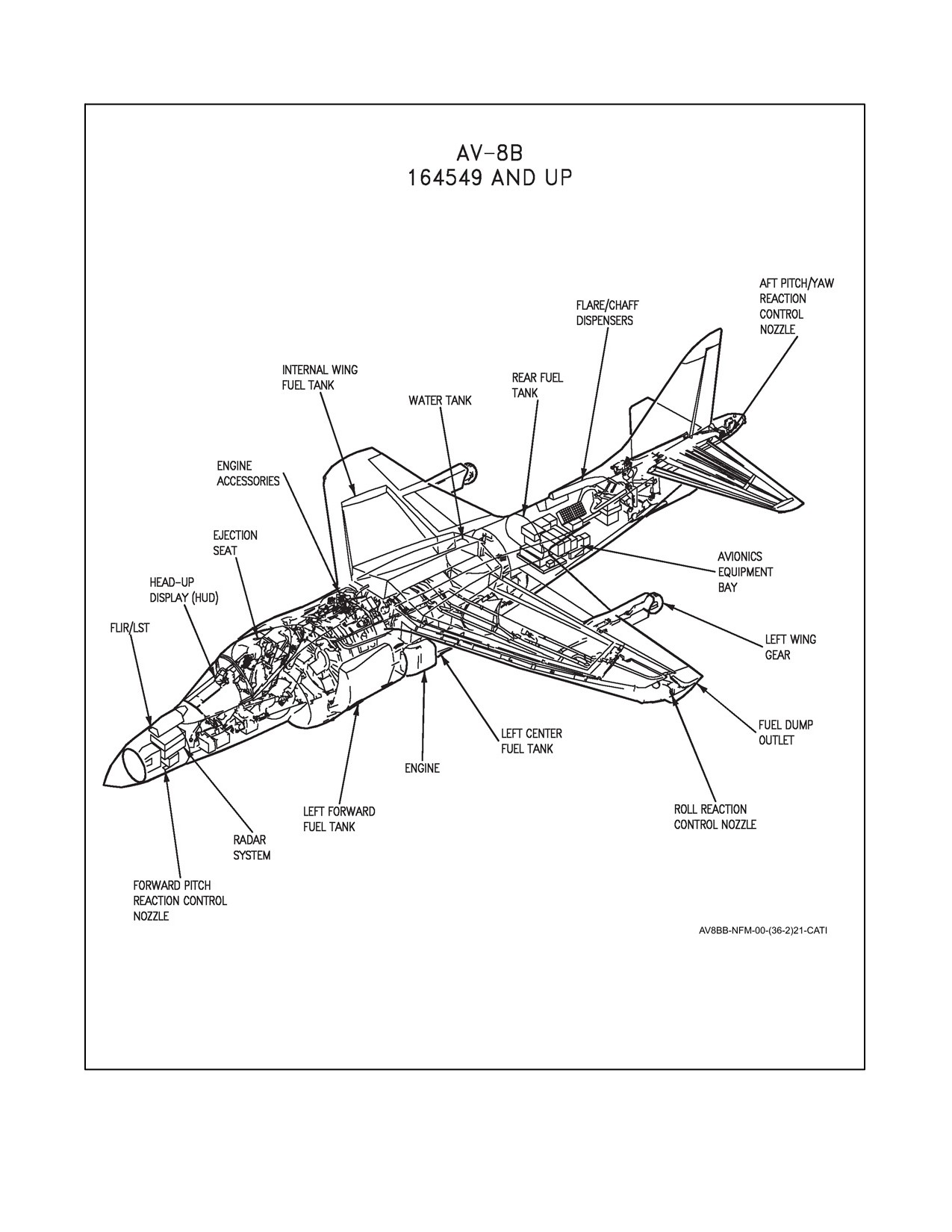
built by McDonnell Douglas Aerospace. Refer to Figure 1-1 for general arrangement. The aircraft is powered by a
Rolls Royce axial flow, twin spool turbo fan engine. Four exhaust nozzles can be positioned and controlled for
vertical/short takeoff and landing
(V/STOL) operation. The aircraft features shoulder mounted swept back
wings with trailing edge flaps and ailerons. The flight controls are hydraulically powered to provide the desired
control effectiveness throughout the speed range. High pressure nitrogen/helium is provided for the landing gear
system during emergencies. The cockpit is pressurized and enclosed by a sliding canopy. A rocket assisted seat is
provided for pilot ejection. Refer to Cockpit illustration, Foldout Section, for instrument arrangement.
1.1.2 Night Attack
The AV--8B night attack aircraft is a modified day attack AV--8B aircraft with the additional capabilities to perform
its mission at night by utilizing low--light attack capabilities.
1.1.3 Radar
The AV--8B radar aircraft is the same as the AV--8B night attack with the APG--65 radar incorporated. The addition
of the APG--65 radar enhances mission effectiveness through improved navigation, air--to--surface, and air--to--
air weapon systems capabilities.
1.1.4 Remanufacture
The remanufactured AV--8B aircraft is an AV--8B day attack aircraft remanufactured to the same configuration as
the radar aircraft, except remanufactured aircraft do not have the electrical wiring to support outrigger pylons. All
references to radar aircraft in this manual will include remanufactured aircraft unless specifically noted otherwise.
1.1.5 Trainer
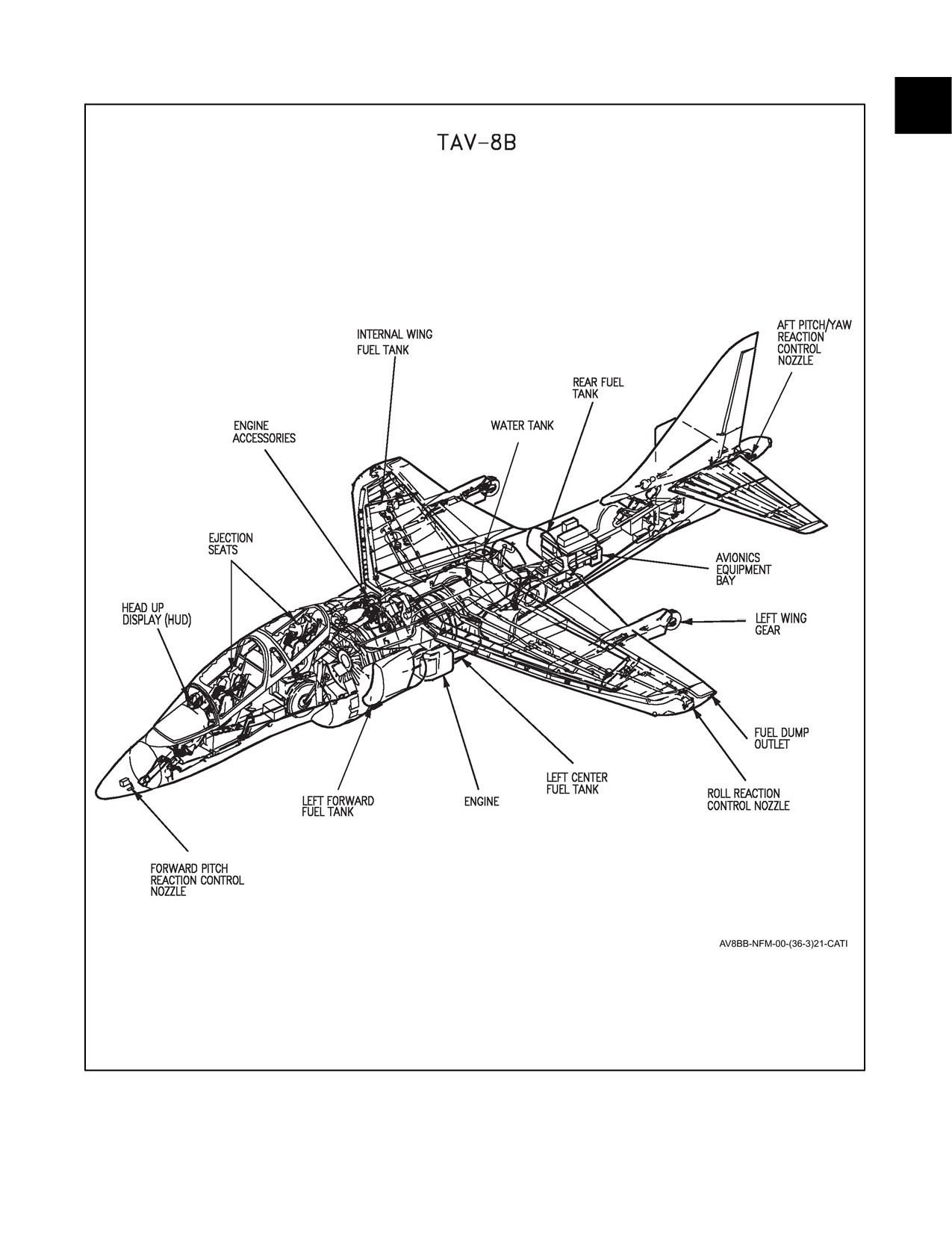
TheTAV--8Bisatransonic,dual cockpit,singleengine,day/nighttacticalfighter/trainerbuiltbyMcDonnellDouglas
Aerospace. Refer to Figure 1-1 for general arrangement.
1.2
AIRCRAFT DIMENSIONS
The approximate dimensions of the aircraft are as follows:
Wing Span
All
30.33 feet
Length
AV--8B
46.33 feet
AV--8B (Radar)
47.75 feet
TAV--8B
50.53 feet
Height
AV--8B
11.65 feet
(top of fin)
TAV--8B
13.09 feet
Wing gear
All
17 feet
spread
1-1
ORIGINAL
A1-AV8BB--NFM--000
1.3
AIRCRAFT GROSS WEIGHT
For specific gross weights, refer to the handbook of Weight and Balance Data NAVAIR 01--1B--40.
The basic weight of an aircraft includes all fixed operating equipment, all oils, and unusable fuel to which it is only
necessary to add the variable or expendable load items for the various missions. Pylons gun/ammo pods, ALE--39,
and fuselage strakes are not part of the Basic Weight.
The operating weight of an aircraft is the basic weight plus those variable items which remain constant for the type
mission. This weight includes pilot, 180 lbs, and all other items except fuel, water, and expendables.
The gross weight of an aircraft is the total weight of an aircraft and its contents.
1.4
MISSION
The AV--8B aircraft is designed for offensive air support and air defense missions. It is equipped to carry and deliver
an assortment of conventional stores, infrared (IR) missiles, laser and global positioning system (GPS)--guided
munitions, and a precision targeting pod from six wing stations and a centerline station. A 25mm gun system may
be attached to the lower fuselage. Refer to NATIP, NTRP 3--22.4--AV8B for additional information concerning
armament deployment.
The AV--8B night attack/radar aircraft has night vision goggle compatible controls and displays.
The AV--8B radar aircraft provides day and night attack missions with improved navigation, air--to--surface and
air--to--air weapon system capabilities.
The TAV--8B aircraft is designed for vertical short takeoff and landing (V/STOL) and Attack training. Refer to the
NATIP, NTRP 3--22.4--AV8B for information concerning armament.
1.5
TECHNICAL DIRECTIVES
As technicalchanges aremadetotheaircraft, thosethat affectaircraft operationorpilotneed--to--know operationwill
beincorporated in the appropriate sections and listed in theSummary of ApplicableTechnical Directives in thefront
of this manual. In some instances, Technical Directives may be incorporated on the aircraft while it is still on the
production line before delivery. Check the Technical Directives Section of the Aircraft Log Book for applicable
modifications. The following are types of technical directives used in this manual:
AAC - Aviation Armament Change.
AFC - Airframe Change.
ASC - Aircrew System Change.
AVC - Avionics Change.
AYC - Accessories Change.
1.6
BLOCK NUMBERS
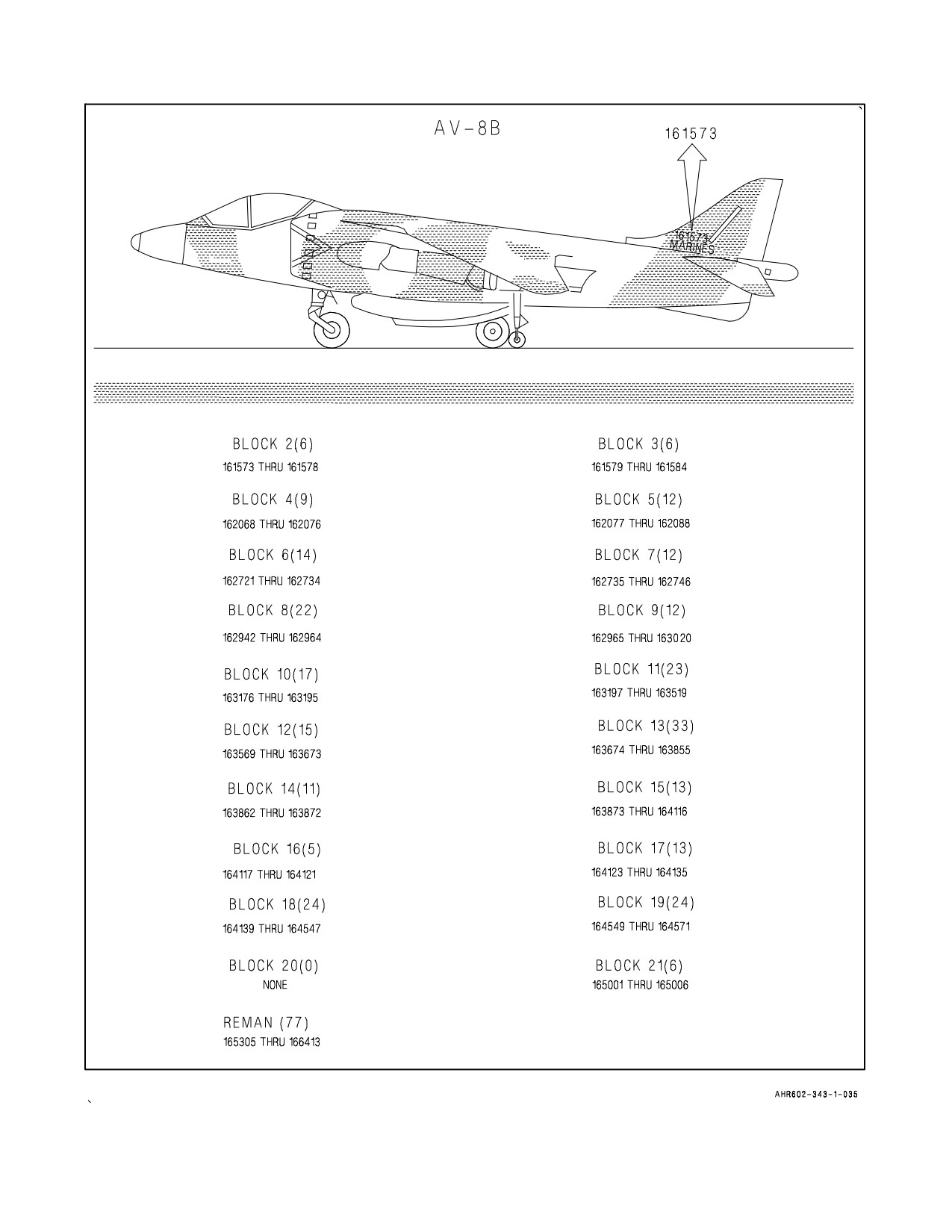
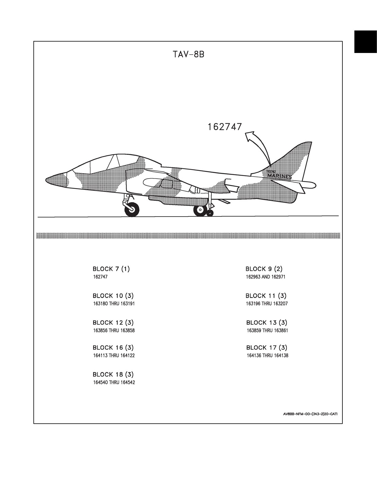
See Figure 1-2 for production block numbers which correspond to aircraft bureau numbers (BUNO).
ORIGINAL
1-2
A1-AV8BB--NFM--000
Figure 1-1. General Arrangement (Sheet 1 of 3)
1-3
ORIGINAL
A1-AV8BB--NFM--000
Figure 1-1. General Arrangement (Sheet 2)
ORIGINAL
1-4
A1-AV8BB--NFM--000
Figure 1-1. General Arrangement (Sheet 3)
1-5
ORIGINAL
A1-AV8BB--NFM--000
Figure 1-2. Block Numbers (Sheet 1 of 2)
ORIGINAL
1-6
A1-AV8BB--NFM--000
Figure 1-2. Block Numbers (Sheet 2)
1-7/(1-8 blank)
ORIGINAL
A1-AV8BB--NFM--000
CHAPTER 2
Systems
2.1
POWER PLANT SYSTEMS
2.1.1 Engine
Each of the aircraft is powered by a Rolls Royce F402--RR--406A, F402--RR--406B, F402--RR--408,
F402--RR--408A, or F402--RR--408B dual spool, axial flow, turbo fan engine with thrust--vectoring exhaust nozzles.
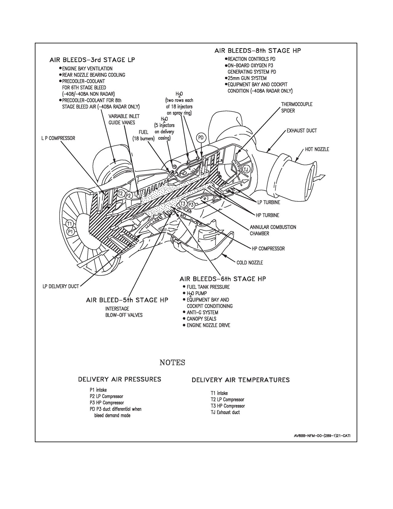
See Figure 2-1. One of the spools is a 3--stage low pressure compressor (fan) driven by a 2--stage low pressure turbine
and the other is an 8--stage high pressure compressor driven by a 2--stage high pressure turbine. Each spool is
independent of the other, but they are coaxial and, to minimize gyroscopic effect, they counter--rotate.
The F402--RR--406A/F402--RR--406B engine, with water injection, develops a nominal (static test bed) thrust of
21,550 pounds in optimum International Civil Aviation Organization (ICAO) conditions or 20,280 pounds without
water injection.
TheF402--RR--406Bengineusesimprovedturbinesectionmaterialsthatresultinincreasedenginelife.Functionally,
the F402--RR--406B engine is the same as the F402--RR--406A engine.
The F402--RR--408 series engine, with water injection, develops a nominal (static test bed) thrust of 23,400 pounds
in optimum ICAO conditions or 22,200 pounds without water injection.
In the remaining portions of this manual F402--RR--406 nomenclature will be used to indicate either the
F402--RR--406AorF402--RR--406Bengines,andF402--RR--408enginenomenclatureshallbeusedtoindicateeither
the F402--RR--408, F402--RR--408A, or the F402--RR--408B engine.
Airdrawnthroughtwointakesentersthefan.Leavingthefantheairis divided,oneflowpassing toan annularplenum
chamber from which it is ducted through front, left and right, cold nozzles. The other flow passes through variable
inlet guide vanes, through the high pressure compressor (HPC) and a combustion chamber to the high pressure (HP)
and low pressure (LP) turbines. It is then ducted through rear, left and right, hot nozzles. Thermocouples in the turbine
exhaust sample gas temperature and supply data to a digital jet pipe temperature (JPT) indicator and to the engine
fuel system for JPT limiter (JPTL). The digital signal is fed to the mission computer for engine life count.
The engine bay is ventilated by ram air intakes at the forward end of the front nozzle fairings and the wing roots. Air
flow is assisted, whenever the engine is running, by flow inducer nozzles supplied by air bleed from the fan; this
ensures that the bay is adequately ventilated in slow and hovering flight.
An engine mounted gas turbine starter/auxiliary power unit (GTS/APU), is used for engine starting or to supply
electrical power.
2.1.1.1 Inlet Guide Vanes
Variable inlet guide vanes (IGV) direct airflow into the HPC to give optimum compressor performance. Their
automatic control unit is adjusted by the HPC rpm and intake air temperature using engine fuel as a hydraulic medium.
On aircraft with a --408B engine, the enhanced variable inlet guide vane system (EVICS) is used to control the IGV’s.
EVICS consists of an inlet guide vane, digital electronic control (IDEC), and a hydromechanical unit (HMU). If the
IDEC fails, the system will revert control of the IGVs to the HMU. At max power the IGVs will be 0 to --4 degrees.
Normal IGV angle at idle will be 31 to 39 degrees. Because there are no inlet guide vanes in front of the fan, an engine
anti--icing system is not necessary. A permanent magnet motor integral to the HMU provides electrical power supply
for the IDEC and lane 2 digital electronics control unit (DECU) (29 Vdc) independent of the aircraft electrical system.
2.1.1.2 Interstage Blow--Off Valves
To promote rapid surge--free acceleration, two compressor interstage blow--off valves open at low rpm to bleed air
from the high pressure compressor into the plenum chamber. The valves close automatically as rpm increases.
2-1
ORIGINAL
A1-AV8BB--NFM--000
Figure 2-1. Engine
ORIGINAL
2-2
A1-AV8BB--NFM--000
2.1.1.3 Lubrication Systems
Oil is drawn from a tank (on the left side of the engine) and circulated by a gear pump to the main engine bearings,
seals, and accessory drives gears. A scavenge system returns the oil to the tank through a fuel--cooled oil cooler. Oil
for the GTS/APU is also taken from the oil tank.
Two green engine oil level lights and a press--to--test button are on a panel (which also contains refueling controls
and a GEN oil light) under an access panel on the left forward nozzle fairing. The lights provide a redundant check
of oil quantity. If at least one of the engine oil lights comes on when the button is pressed, there is enough oil for at
least a 3 hour flight (16 pints).
The tank is normally pressure refilled through a coupling on the left front side of the engine. Full is indicated by
discharge from an overflow pipe beside the coupling. Ferry levels are obtained by capping the overflow pipe and
gravity filling the tank through a filler neck under a panel on top of the fuselage. The various oil fill amounts are as
follows:
One Light - 16 Pints - 3 Hrs.
Full - 19.2 Pints - 4 Hrs.
Ferry - 26 Pints - 7.5 Hrs.
Extended Ferry - 33 Pints - 10 Hrs.
Breather air is vented from the engine, the gearbox, and the oil tank through an air/oil separator to a discharge just
forward of the right cold nozzle. Low oil pressure is indicated by an OIL caution light on the caution light panel.
2.2
AIR INDUCTION SYSTEM
The air induction system consists of two semicircular side inlet ducts that merge at the engine face. The inlet ducts
utilize boundary layer doors and intake suction doors to compensate for the wide range of airflow requirements
induced by the aircraft V/STOL and high speed flight capabilities.
2.2.1 Boundary Layer Doors
Two doors on the fuselage skin of each air intake are spring--loaded closed during slow and hovering flight. In high
speed flight, when boundary layerpressureis high, thedoors areforced open against theirsprings and airis bled from
the intakes, thus preserving smooth airflow to the engine. The bleed air is ducted internally to exhaust behind thetop
of the cockpit canopy. The pairs of doors normally function together, but the doors of each pair can operate
independently to improve airflow to the engine.
2.2.2 Intake Suction Doors
Auxiliary air inlets around the outside of each air intake are covered by unrestrained hinged doors, which are held
open by suction to increase air flow to the engine during slow and hovering flight when air intake pressure is low.
During high speed flight, the doors are held closed by increased intake air pressure.
2.3
ENGINE FUEL SYSTEM
The main components of the engine fuel system consist of the digital engine control system (DECS), two fuel
manifolds, 18 flow distributors, two torch igniters, five primer jets, dump valve and tank. Fuel is available to the
engine when the throttle lever is moved forward from the cutoff position, provided the fuel shutoff valve is open.
2.3.1 Digital Engine Control System
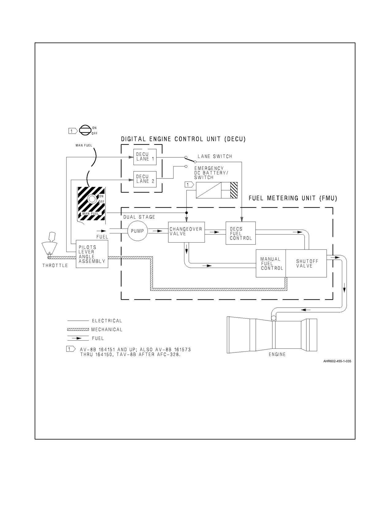
DECS is a nearly full authority digital engine control system (Figure 2--2). The DECS provides engine control
throughout theengineoperating rangein responseto throttleposition, altitude, airspeed, angle ofattack (AOA), inlet
air temperature, and aircraft configuration. DECS automatically compensates for changes in fuel density, bleed air
usage, and engine condition while maintaining engine performance. The four main components of the DECS are a
pilot lever angle (PLA)assembly, two identical DECUs and afuel metering unit (FMU). The PLA senses thethrottle
position through a mechanical linkage to the throttle. An electrical signal is sent from the PLA to the two DECUs.
The two DECUs are each capable of full independent electronic control authority and command the mechanical FMU
2-3
ORIGINAL

A1-AV8BB--NFM--000
to provide properly metered fuel to the engine. Only one DECU is in control of the FMU at any one time. The EFC
caution (amber) light illuminates (with audio warning) in the cockpit upon either DECU failing. In the event of the
controlling DECU failing, engine control will automatically transfer to the other DECU. If the non--controlling
DECU fails the EFC caution will still illuminate, but without a lane change occurring. Should the remaining DECU
fail, engine control is lost and the EFC warning (red) light illuminates (with audio warning). Engine control can be
regained by selection of the manual fuel system (MFS) which is incorporated within the FMU (provided fuel pressure
and dc electrical power are available).
2.3.1.1 Digital Electronic Control Unit
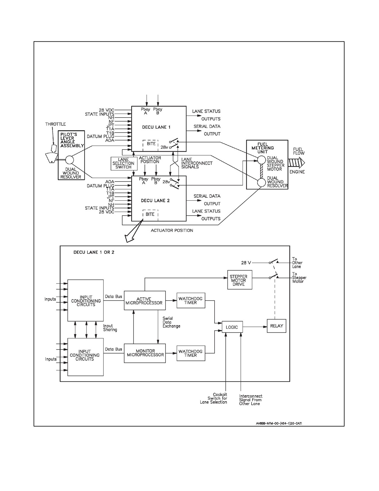
Two identical DECU, each capable of nearly full control authority are bolted together to form a single unit and are
mounted on the top right side of the engine (Figure 2-3). The DECU electronics are contained within a cast metal
casing through which fuel is passed for cooling. Each is driven by a separate 28 Vdc power supply (LANE 1 --
Switched Battery Bus, LANE 2 -- Emergency DC Bus); on AV--8B 161573 through 163852, TAV--8B 162747 through
163861 after AFC--370 or AV--8B 165354 and up; also AV--8B 163853 through 165312, TAV--8B 164113 through
164542 after AFC--395, if a DECU’s power supply is lost a crossover circuit allows it to be powered by the bus of
the other DECU. On aircraft after AFC--392 LANE 2 is also provided 29 Vdc power from the inlet guide vane control
(IGVC) digital electronic control (IDEC). When aircraft dc power is on, DECUs are enabled when the DECS enable
switch is ON.
Any power fluctuation under 16 volts will disable the DECU and may cause any one of the following:
1. EFC Caution (amber)
Loss of power to either DECU
JPTL Warning (red)
2. EFC Caution (amber)
Loss of power to both DECU
JPTL Warning (red)
EFC Warning (red)
Chapter 12 outlines procedures.
JPTL and EFC lights are NVG green on Radar and Night Attack aircraft.
Each DECU receives independent signals from engine and airframe transducers and switches, together with the
pilot’s throttle signal. Signals concerning the state of the aircraft (e.g. weight on wheels, JPTL switch, H2O switch,
etc.) are called STATE inputs. The validity of all these signals is cross--checked by dual microprocessors within each
DECU (one active, one monitoring). If the validity is good, the controlling DECU outputs signals to the stepper motor
which in turn controls a fuel metering valve in the FMU and thus controls engine rpm. If a discrepancy is detected
between the processors, the DECU electrical output drive signal to the stepper motor is removed, an EFC caution
is signaled, and the EFC dolls eye failure indicator in the refueling panel (22L) is tripped. The other DECU senses
theremovalofelectrical drivesignal fromthesteppermotorbytheselectedcontrolling DECUand immediatelytakes
control by applying its drive signal to the stepper motor. In either case an EFC caution will illuminate and the EFC
dolls eye failure indicator will be tripped.
In the event of a dual DECU failure being detected (EFC warning light and voice warning) electrical power to the
FMU stepper motor will be lost. When electrical power is removed from the stepper motor, it remains magnetically
latched in its last commanded position. FMU fuel metering valve position is dependent upon stepper motor position
and the high pressure compressor discharge pressure (P3) signal. Therefore, even though the stepper motor is
magnetically latched in the event of a dual DECU failure, actual engine speed may increase, decrease, or remain the
same depending upon the engine condition at the time dual DECU failure occurred. If the failure occurs while the
engine is either accelerating or decelerating, the engine will likely continue to accelerate or decelerate, and in the
extreme case may either overspeed or run down sub--idle. If the failure occurs with the engine operating at a steady
speed above approximately 90 percent, the speed will likely remain approximately constant, with changes in speed
occurring with changes in altitude. If the failure occurs below approximately 90 percent, the speed may not remain
constant. Engine control may be regained by selecting MFS.
ORIGINAL
2-4
A1-AV8BB--NFM--000
Known susceptibilities to speed signal noise within the current configuration of DECU software (504) have resulted
in multiple occurrences of dual DECU failure in service. The most significant failure mechanism occurs within in
the last 1.0 seconds of demanded engine acceleration to short lift rating. In these instances, significant overspeeds
in excess of 128 percent rpm have occurred. Engine control may be regained by selecting MFS, however, maximum
scheduled fuel flow and therefore maximum engine thrust available may be less than that normally available under
DECS control for the same prevailing conditions.
In the event of an aircraft electrical failure occurring on aircraft with AFC--392 incorporated, LANE 2 and the IGVC
willbothremainelectricallypoweredbytheIGVCdedicatedgeneratorandenginecontrolwill bemaintained. LANE
1 DECU and the opportunity to select MFS will both be eventually lost as battery voltage drops below 16 volts.
Aircraft with AFC--328 incorporated will maintain the opportunity to select MFS, if required, through actuation of
the MFS emergency battery.
In the event of an aircraft electrical failure occurring on aircraft without AFC--392 incorporated, digital engine control
and the opportunity to select MFS will both be lost as battery voltage drops below 16 volts. As battery voltage
approaches 16 volts, FMU stepper motor movement and therefore engine response may become sluggish as battery
powerdiminishes. On aircraft without AFC--328 incorporated, MFS should beselected as soon as possible and prior
to battery voltage reducing below 16 volts. On aircraft with AFC--328 incorporated, MFS should still be selected
as soon as possible and prior to battery voltage dropping below 16 volts. However, the emergency battery should
provide an alternative power supply to allow MFS selection.
If the engine remains stable following EFC control loss the rpm will increase in a descent at constant Mach number
and decrease during deceleration at constant altitude. A descent from high altitude cruise to pattern altitude and speed
can result in a loss of rpm of up to 5 percent. As nozzles are selected and as bleed is demanded, rpm will decrease.
If the initial rpm prior to nozzle selection is at 80 percent or below, the effect of bleed may run the engine to a sub--idle
condition. At higher initial rpm and with maximum bleed the reduction in rpm may be up to 20 percent.
Pilot DECU selection is controlled by setting the EFC switch to POS 1 (LANE 1) or POS 2 (LANE 2) as required.
Repositioning the EFC switch with a single DECU failure could reset a failed DECU that is now processing erroneous
data.
2.3.1.1.1 Throttle Position Sensor Assembly
The pilot’s lever angle (PLA) assembly provides each DECU with electrical throttle position signals. The PLA
assembly is attached to the FMU and is driven by the throttle linkage.
2.3.1.2 Total Temperature Probes
Total temperature probes are mounted on the inboard wall of each main engine inlet. The probes are used by DECS
to calculate corrected engine speed. Operation of the probe heaters is covered under Probe Heat Switch in the
Instruments section.
2.3.1.3 Engine Fast Deceleration Solenoid
To avoid aircraft bounce on vertical landing, DECS incorporates a fast deceleration solenoid that is armed for 1 second
by the weight on wheels (WOW) switch. A rapid throttle chop will activate the fast deceleration system and
immediately reduce fuel flow. For aircraft with IPPC--227 incorporated, the engine fast deceleration solenoid is
disabled.
2.3.1.4 Fuel Filter Blockage
If an abnormally high pressure drop is experienced across the FMU filter, a resettable low pressure fuel blockage
indicator on the filter unit will pop--up and latch the engine fuel control fault indicatoron theaircraft refueling panel.
Excessive fuel pressure drop, caused by a complete filter blockage, will open the by--pass valve and activate a non
resettable pop--up indicator on the filter unit.
2-5
ORIGINAL
A1-AV8BB--NFM--000
Figure 2-2. Digital Engine Control System
ORIGINAL
2-6
A1-AV8BB--NFM--000
Figure 2-3. Digital Engine Control Unit
2-7
ORIGINAL
A1-AV8BB--NFM--000
2.3.1.5 P3 Limiter
The P3 limiter (combustion chamber pressure limiter) vents the DECS P3 air pressure signal to the atmosphere when
P3 pressure exceeds the limit value. The drop in the DECS P3 airpressure signal causes theFMU to reduce fuel flow
thereby reducing engine internal operating pressure preventing possible engine overpressure resulting in structural
damage. The engine is most likely to operate on the P3 limiter during low altitude, high airspeed conditions with cold
ambient temperatures (--408 engine may include ISO standard ambient temperatures and below). P3 limiting may
begin as airspeed exceeds 475 KCAS (standard day) and may be noticed by the pilot as rpm fluctuations on the order
of one to three percent rpm. These fluctuations will occur at a rate of two to three per second. Reducing the throttle
slightly will cause the fluctuations to stop.
2.3.1.6 DECS Limiting
For the F402--RR--406 engine the jet pipe temperature (JPT) is limited to 727 °C for short lift wet, 703 °C for short
lift dry, 665 °C for Combat, and 625 °C for maximum thrust.
For the F402--RR--408 engine the JPT is limited to 800 °C for short lift wet, 780 °C for short lift dry, 750 °C for
combat, and 710 °C for maximum thrust.
JPT limiting inputs include JPTL switch, gear position, nozzle position, water injection switch position, air data
computer (ADC) airspeed, and combat mode switch position. With gear down, or nozzles greater than 16° down, the
short lift wet or dry datum is selected depending on the water arming switch position, if the combat mode switch in
the main wheelwell is in the ENABLE position. If the combat mode switch is in the DISABLE position, DECS will
limit rpm to 99 percent for the --406 engine and 109 percent for the --408 engine when above 250 knots. With gear
up, nozzles aft, and combat mode switch in the enable position, the maximum thrust or combat datum is selected by
thecombatselectswitch.Selectinglimiteroff,thenreselectinglimiteronwillresultinupto15--seconddelayinactive
limiting of JPT under DECS control. During this time, the pilot must manually maintain JPT limits.
2.3.1.6.1 Compressor Speed Limiting at Altitude
DECS limits the corrected compressor speed based on altitude and angle of attack (AOA). Above 18,000 feet the
DECS will reduce the limiting corrected compressor speed and slow the engine acceleration rate as AOA increases.
This angleofattack cutback will reducethelikelihood ofan enginesurge. With an ADC failure (loss of AOA signal),
DECS will control the corrected compressor speed and engine acceleration rate as though the aircraft were at
maximum AOA. This backup schedule only impacts engine operation above 18,000 feet. In the event of AOA loss
above 18,000 feet the cutback in corrected compressor speed and acceleration rate will reduce maximum available
engine thrust and therefore impact aircraft performance. Engine surge protection will be at its highest level for the
given aircraft altitude.
2.3.1.7 Bleed Air Pressure Switch
The bleed air pressure switch (BAPS) automatically compensates for the change in fuel flow demand due to reaction
control system bleed.
2.3.2 Fuel Metering Unit
The FMU is located on the engine fan case aft of the DECU. The FMU contains the hydromechanical controls
required to pump, filter, and meter fuel. It is divided into a primary (DECU controlled with P3 inputs) and a manual
fuel system (MFS).
The DECU control inputs are provided to a stepper motor which in turn operates a fuel metering valve to properly
meter fuel for a desired engine response. The fuel metering valve is also controlled by P3 pressure inputs. Partial or
total loss of the P3 signal pressure due to line leakage can result in a large loss in thrust and fuel flow to the engine.
ThePLAunitisattachedtotheFMUandis drivenby thepilots throttleinput shaft.ThePLAprovides twoelectrically
independent signals to each DECU. A solenoid operated change--over directs fuel to either the primary fuel control
(DECU) or MFS.
ORIGINAL
2-8
A1-AV8BB--NFM--000
The MFS enables the engine to continue operating following a failure within the primary fuel control system. The
solenoid operated changeover valve must have fuel pump pressure and dc electrical power available to successfully
select MFS. Below 16 volts, normal manual fuel selection cannot be guaranteed. In MFS the throttle lever is
mechanically linked to the throttle valve on the FMU and the valve opening is governed strictly by throttle lever
position.
2.3.3 Manual Fuel System
The MFS provides an alternate means of engine control if the primary fuel control system fails. Engine handling and
relighting are adequate for emergency recovery. MFS is selected by actuation of the MAN FUEL switch located in
the striped area of the throttle quadrant panel or on AV--8B 164151 and up; also AV--8B 161573 through 164150,
TAV--8B 162747 through 164542 after AFC--328 by activating the MFS EMER BATT located outboard of the throttle
nozzle quadrant.
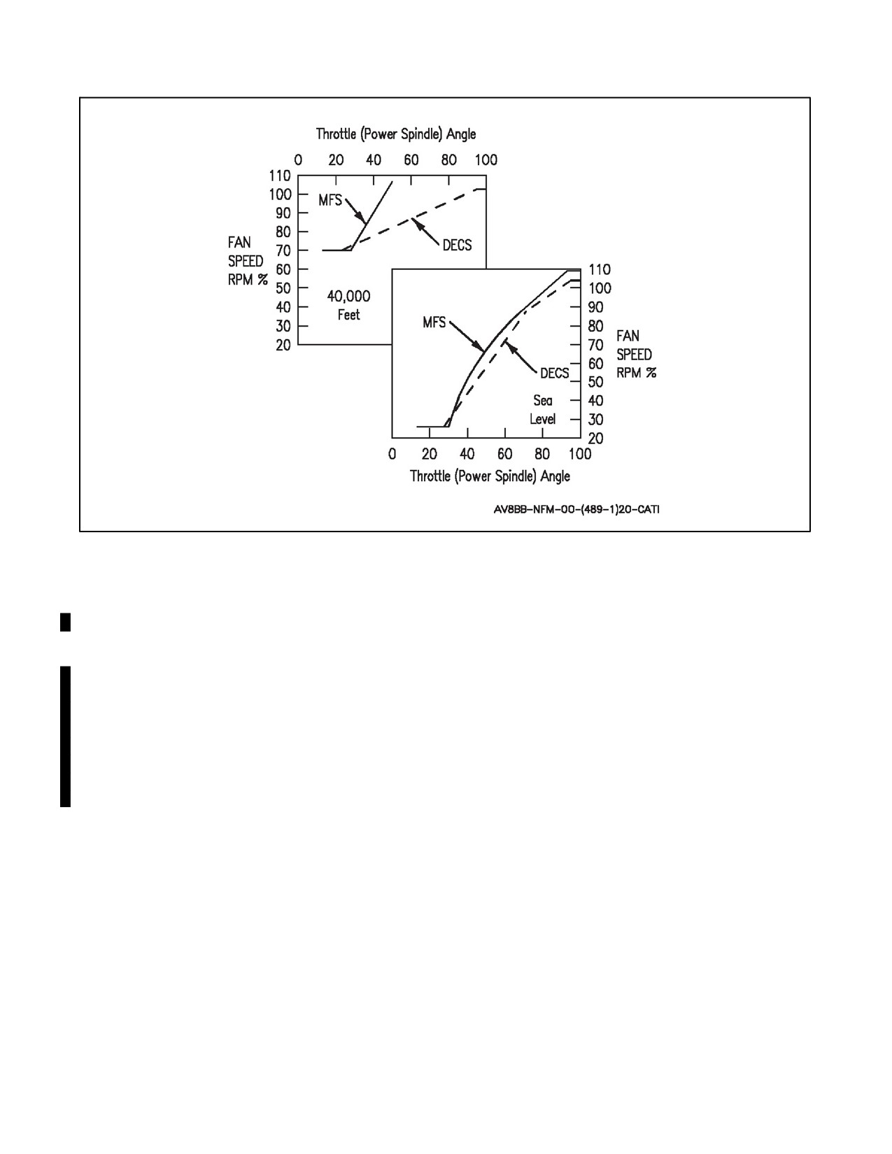
With MFS control, the engine response is more sensitive to throttle movement because the MFS does not contain
any automatic altitude compensation, acceleration controls, or limiters. See Figure 2-4 for a comparison between
DECS and MFS. The MFS is basically a fuel tap and engine rpm is controlled only by the throttle and engine operating
conditions (speed, reaction control system (RCS) bleed extraction and environment). MFS is fuel flow limited to a
maximum scheduled flow of approximately 260 pounds per minute at maximum throttle position. Maximum throttle
position in MFS at near sea level static conditions with nozzles at 10 degrees and neutral flight controls will provide
approximately 111.0 percent corrected fan speed versus the 116.8 percent corrected fan speed limitation provided
under DECS control. Actual mechanical speed and thrust achieved in MFS will vary with RCS bleed extraction rate,
water injection usage and ambient conditions. Anticipate maximum achievable MFS performance equal to or slightly
less than short lift dry performance under DECS control when operating near sea level static conditions. The throttle
lever is mechanically linked to the throttle valve on the FMU and the valve opening is governed strictly by throttle
lever position. Engine acceleration rate is controlled by throttle movement. Care should be taken to limit throttle
operation to control the engine manually within its normal acceleration limitations. The engine is quite sensitive to
over fueling when rpm is below 75 percent therefore throttle movement should be slow and smooth. Care should be
taken not to move the throttle faster than the engine will normally accelerate when controlled by the primary fuel
control system. At sea level, moving the throttle from the idle stop to the mid--throttle position in less than 6 seconds
or, at any altitude, moving the throttle without appropriate engine rpm response, greatly increases the risk of engine
surge. Since the possibility of surge is greater at low rpm, throttle movement must be slowest in the lower portion
of the rpm band. (Approximately 4 seconds from idle to 55 percent and 2.5 seconds from 55 percent to 100 percent).
Above 75 percent rpm the engine is quite tolerant to throttle movement at lower altitudes (semi--jetborne or jetborne
flight).
The sensitivity of MFS increases with an increase in altitude since fuel flow remains constant with throttle lever
position and approximates to that of the DECS only at sea level (Figure 2-4). Flight testing has shown that at 40,000
feet only one inch of throttle movement from idle may provide combat thrust. All throttle movements should be made
with specific reference to the rpm indicator. Even at medium altitude, maximum rpm may be achieved with as little
as half the full throttle lever travel. Preferably MFS selection should be accomplished at idle throttle, but in time
critical emergencies may be selected up to full throttle. Selection of MFS with low engine rpm and high throttle lever
angle position significantly increases the likelihood of engine surge. With MFS selected, the engine is cleared for
operation in all flight regimes. Pilot should cross--check RPM, JPT, and corrected fan speed to maintain the engine
within limits.
When operating in MFS the igniters and primer solenoid are continuously energized. They can be secured to either
minimizethedrain on thebattery in atotal electricalfailure, orlimit componentwearbymomentarily selectingeither
OFF or ALERT with the battery switch. This procedure requires that all other electrical power is off prior to
momentarily securing the battery. Continuous ignition can be restored by momentarily selecting the MFS switch to
ON. The igniters and primer valve can be operated at any time by pressing the airstart button. Operating in the MFS
without continuous ignition gives a slightly increased chance of engine flameout on slam deceleration.
2-9
ORIGINAL
A1-AV8BB--NFM--000
Figure 2-4. DECS/MFS Comparison
2.3.3.1 Effect of Water Injection on Thrust
When water is introduced into the engine, it runs less efficiently for a given metered fuel flow. Therefore, when water
flows, the available thrust is reduced. In DECS, fuel flow is automatically increased to compensate for the power loss
and to increase the rpm to the wet datum. An overall increase in rpm will be seen. In MFS, fuel flow is defined by
throttle position and engine operating condition (speed, RCS bleed extraction and environment) and is flow limited
to a maximum of approximately 260 pounds per minute at maximum throttle. Subsequently, at maximum throttle
position, scheduled fuel flow available is constant and maximum rpm and thrust will decrease in response to the
reduction in power resulting from water injection. The speed and thrust reductions may be up to approximately 2
percent corrected fan speed and 1000 pounds of thrust compared to the expected dry values. If the throttle is steady
(at full power for example) then thrust will be reduced when water flows compared to the expected dry value. The
thrust reduction may be up to 1,000 pounds. If water is flowing while operating in MFS and more thrust is required,
the water must be selected off.
2.3.3.2 Manual Fuel Switch
The MAN FUEL switch is located in the striped area of the throttle quadrant and is a three position switch spring
loaded to center. The switch must be actuated until the MFS caution illuminates or extinguishes to achieve MFS
selection or deselection as appropriate. Up to one second may be required. The switch energizes a solenoid which
magnetically latches in the MFS or DECS position. A minimum of 16 volts is required to move the solenoid, however,
switchingmaybeachieved withas lowas 5volts available.Thesolenoiddirects fuelpressuretothechangeovervalve
to achieve the required change, which is signalled by the MFS caution. Therefore, if MFS is selected or deselected
with the engine off, the full change over will not take place until the engine is starting and fuel pressure becomes
available, the MFS caution will then signal the change. The ignitors and primer solenoid will still operate according
to the selection of the MFS switch. The igniters are not rated for continuous operation; therefore, if operational
conditions permit, the MAN FUEL switch should be placed to OFF before engine shutdown. DC power is required
to switch from DECS to MFS when using the MAN FUEL switch. Inflight, once manual fuel has been selected, it
should not normally be deselected.
ORIGINAL
2-10
A1-AV8BB--NFM--000
ON - Engine control transferred from DECS to MFS.
(Center) - Neutral position.
OFF - Engine control transferred from MFS to DECS.
2.3.3.3 MFS Emergency Battery
(AV--8B 164151 and up; also AV--8B 161573 through 164150, TAV--8B 162747 through 164542 after AFC--328).
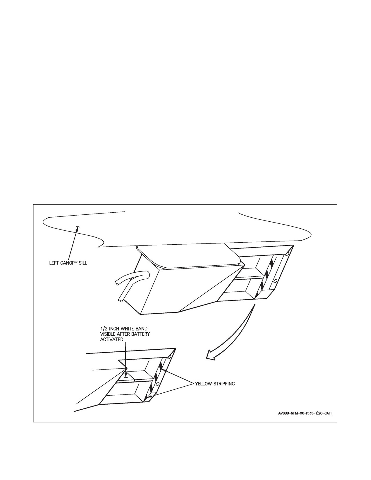
The MFS EMER BATT is located on the left cockpit left of the throttle grip. The MFS EMER BATT is a one shot
battery device for selecting MFS when electrical power is lost or as an alternate means for selecting manual fuel. The
battery is activated by extending the pull shaft forward approximately 1/2 inch. Once the battery is activated, the
manual fuel solenoid is magnetically latched in the MFS ON position regardless of the position of the manual fuel
switch. MFS cannot be deselected using the battery. However, if electrical power is restored MFS can be deselected
using themanual fuel switch. Theactivation rod is mechanically locked to prevent reseating ofthehandle. A 1/2 inch
white band on the exposed portion of the rod provides a visual indication that the battery has been activated. After
selection, maintenance must replace the battery. See Figure 2-5 for MFS emergency battery.
2.3.3.4 MFS Caution Light
The MFS caution light, on the priority caution light panel, illuminates any time the engine fuel system is in the manual
fuel mode. If the MFS caution light illuminates when operating under DECS control, MFS should be selected ON.
On AV--8B 163519 and up, TAV--8B 163856 and up, a MANUAL FUEL, MANUAL FUEL voice warning, is
provided in conjunction with the MFS caution light.
Figure 2-5. MFS Emergency Battery
2-11
ORIGINAL
A1-AV8BB--NFM--000
2.3.4 Fuel Distribution System
The fuel distribution system consists of a fuel distribution valve, upper and lower manifolds, flow distributors and
a dump valve. The fuel distribution valve is located on the FMU and functions to provide system back pressure and
correct proportion of FMU scheduled flow between the upper and lower manifolds. The upper and lower manifolds
are positioned around the circumference of the engine HP delivery casing and distribute the fuel to the 18 flow
distributorsarrangedinpairsaroundthedeliverycasing.Thedistributorsdeliverfuelintothe18 combustionchamber
vaporizer tubes with appropriate swirl to enhance vaporization.
2.3.4.1 Torch Igniter Valve and Primer Jets
This solenoid valve is open during the engine starting sequence and supplies fuel to five(--406) ortwo (--408)primer
jets.
2.3.4.2 Dump Valve and Tank
A spring--loaded open dump valve is held closed by primary manifold pressure when the engine is running. During
engine shut down, the valve opens and fuel from both the primary and secondary manifold drains into a dump tank.
During wingborne flight, any fuel in the dump tank is automatically siphoned overboard. A normal start/stop cycle
dumps approximately 1.2 pints offuel into the dump tank. A tank overflow outlet dumps fuel overboard if morethan
5 engine start/stop cycles are made between flights.
2.3.5 Engine Monitoring System (TAV--8B 163856 and up, AV--8B 163176 and up)
The engine monitoring system (EMS) consists of the engine monitoring unit (EMU) and advanced memory unit
(AMU). While the engine is running, the EMU continuously monitors engine mounted sensors (vibration, pressure),
the DECS and several airframe inputs to detect engine anomalies. Engine operations which exceed specific datum
limits and component failures are detected and a summary of these incidents can be displayed on the DDI
(MENU/ENG/EMS). Certain parameter exceedances activate the ENG EXC caution light on the caution/advisory
light panel for the incident duration. Those exceedances are engine overspeed, overpressure, temperature and engine
vibration exceedance. All incidents latch the mechanical EMU indicator on the aircraft refueling panel (door 22L).
The EMU also processes data to calculate engine life counts which can be displayed on the digital display indicator
(DDI) (MENU/ENG/EMS/CTS).
When the EMU detects a parameter exceedance (incident), a time--history of 36 engine and aircraft parameters is
recorded and sent to the data storage set (DSS) or AMU Maintenance Card for storage and post--flight analysis. The
length of time--history depends on the incident, but can vary from 16 seconds before to 4 seconds after incident
detection for a Pilot Record and to 4 seconds before and 16 seconds after for an airstart. A summary of all in--flight
incidents and engine life counts is automatically sent from the EMU to the DSS or AMU at the end of a flight for
post--flight analysis and archive.
2.3.5.1 EMS Button (Pilot Record)
The EMS button provides a method of EMU manual initiation and is located on the throttle quadrant. When the button
is depressed, the EMU records on the DSS or AMU Maintenance Card a time--history of 36 engine and aircraft
parameters which will be available for post--flight analysis. The time--history stored on the DSS or AMU
Maintenance Card contains data from 16 seconds prior to button depression and continues for a further 4 seconds.
2.3.6 Ignition System
During engine start, fuel is pumped, via the torch igniter valve, into a vaporizing chamber through two primer jets
adjacent to the two torch igniters and three auxiliary primer jets. When the airstart button on the front of the throttle
is pressed the ignition system is energized and will remain so until the button is released. The irregular crackle of
the igniters can be heard if the airstart button is pressed before engine start up; this is a preflight check of the torch
igniters.Aregularcrackleindicates failureofoneoftheigniters. BothDC poweredpumps areautomatically onwhile
the airstart button is pressed. Ignition is automatic during starting cycle; it is also automatic and continuous when
manual fuel is on.
ORIGINAL
2-12

A1-AV8BB--NFM--000
2.3.6.1 Battery Switch
The battery switch is on the right console. The switch must be in the BATT position before the GTS and engine can
be started. Three positions exist for the battery switch. Refer to DC Electrical Power for system description.
2.3.6.2 Ignition Isolation Switch
The ignition isolation (IGN ISO) switch on the ground power panel is lever--locked to the OFF position. With the
switch in OFF, ignition is automatically provided during engine start. Placing the switch to ON disables the normal
start ignition and allows the engine to be wet or dry cycled without ignition.
2.3.6.3 Engine Start Switch
The engine start switch is located on the right console. Placing the switch to ENG ST initiates the GTS and engine
starting sequence (fwd cockpit only on TAV--8B aircraft).
2.3.7 Water Injection System
The water injection system enables rpm to be increased for a given turbine entry temperature to sustain short lift wet
and normal lift wet ratings at temperatures up to ISA +15 °C. The main components consist of a water tank, air turbine
pump, water filter and pressure switch, water manifold injectors, engine fuel control, bleed air supply, a short lift
thrust relay, an airspeed relay and an H2O control relay. A flow control valve allows warm air to heat the system
components at low temperature to keep them from freezing.
2.3.7.1 Water Switch
The water injection switch is on the left main instrument panel. The switch is labeled H2O and has positions of TO
(takeoff), LDG (landing) and OFF.
TO or LDG
Water injection system is armed (engine JPTL datum changed) and the engine fuel control
provides supplementary fuel resulting in an engine rpm rise at IDLE. The --406 engine
increases 3.3 to 4.3 percent, and the --408 engine increases 6.0 to 7.0 percent.
TO
Water flows when the throttle is set above 95 percent rpm for the --406 engine and 105 percent
rpm for the --408 engine.
After takeoff, water continues to flow until airspeed exceeds 250 knots, water is depleted, OFF
is selected, or the throttle is moved below 95 percent rpm for the --406 engine or below 103
percent rpm for the --408 engine.
LDG
Water flows when airspeed is below 250 knots, jet pipe temperature exceeds
684 °C (Night Attack aircraft with --406 engine and TAV--8B 164113 and up),
687 °C (Day Attack aircraft with --406 engine and TAV--8B 162747 through 163861),
765 °C (--408 engine),
and the throttle is set above 95 percent rpm for the --406 engine or 105 percent rpm for the
--408 engine.
Water flow stops only if water is depleted, OFF is selected, or the throttle is moved below 95
percent rpm for the --406 engine or 103 percent rpm for the --408 engine.
After initial water flow, water will flow each time the throttle is set above 95 percent or 105
percent rpm, as applicable, regardless of the JPT until the LDG mode datum is reset by cycling
the H2O switch.
OFF
Shuts off water injection system. The OFF position must be manually selected to reset the
engine jet pipe temperature limiter datum and engine fuel system.
2-13
ORIGINAL
A1-AV8BB--NFM--000
2.3.7.2 Water Injection Switch (AFT Cockpit)
The rear cockpit water injection switch is located on the lower left main instrument panel. The switch is labeled H2O
and has positions of TO and FWD.
TO - Overrides forward cockpit switch and arms water injection system.
FWD - System controlled by forward cockpit switch.
2.3.7.3 Water Flow Light
A green water advisory flow light on the engine display panel (EDP) comes on displaying a W when water injection
is selected and water is flowing. If the flow light (W) does not come on, indicating no water flow, the lift rating JPT
limit can be reached very quickly.
2.3.7.4 H2O SEL Caution Light
The H2O SEL caution light on the caution/advisory light panel comes on if the water switch is in TO or LDG and
airspeed is above 250 knots.
2.3.7.5 H2O Light
The H2O caution light on the priority caution panel comes on when water injection is selected and less than 15 seconds
of water remains. The light stays on after all water is consumed or until the water switch is placed to OFF. On TAV--8B
163856 and up, AV--8B 163519 and up, a WATER, WATER voice warning is provided in conjunction with the H2O
caution light.
2.3.7.6 Water Dump Switch
The water dump switch is on the left console and has positions of DUMP and OFF. The switch is lever--locked in
the OFF position (fwd cockpit only on TAV--8B aircraft).
DUMP - Water is dumped.
OFF - Dumping is stopped.
2.3.7.7 Water Tank
The water tank is located in the engine bay, just aft of the engine. It contains approximately 500 pounds of distilled
or demineralized water with flow duration of approximately 90 seconds. The tank is replenished by gravity filling
via a filler cap on the top surface of the fuselage. A water quantity probe extends down into the tank. This signals
a quantity gauge transmitter, operates an H2O (approximately 15 seconds of water remaining) caution light on the
priority caution light panel and also ensures, by deenergizing a low level switch, that the system cannot produce
delivery pressure if initially there is less than approximately 25 pounds of water in the tank. The H2O caution light
also illuminates and the water pump shuts down during normal operation if the water pressure drops below acceptable
limits or the quantity is less than approximately 25 pounds. Repeated use of water other than distilled or
demineralized will cause engine performance to deteriorate.
2.3.7.8 Water Injection System -- Conditioned Air
To prevent freezing in the water system, a thermal switch and flow control valve taps hot bleed air and circulates it
around the system.
2.3.8 Thrust Vectoring
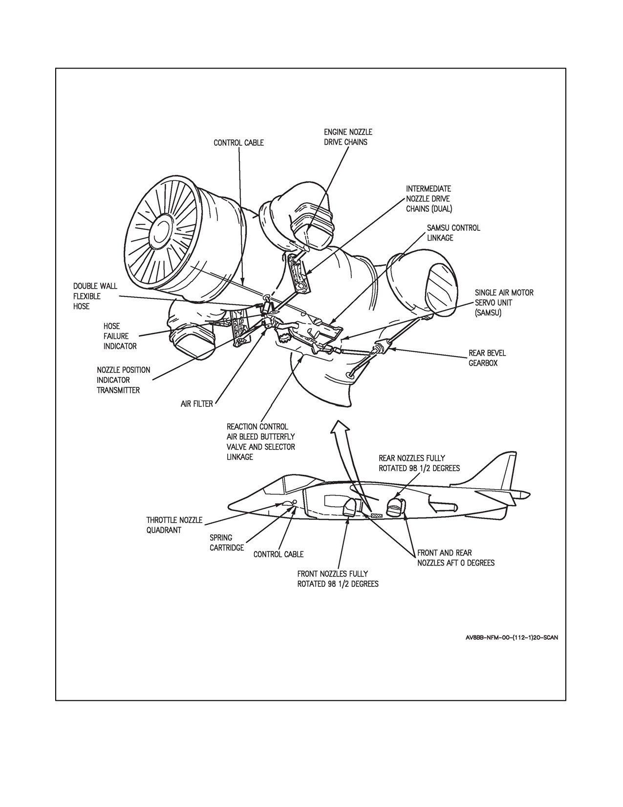
The four nozzles are mechanically interconnected and can be simultaneously rotated by a lever in the cockpit, from
fully aft through a 98° arc to a forward braking position to vector the engine thrust. The nozzle mechanism (Figure
2-6) also operates a butterfly valve lever to supply bleed air to the reaction controls. The system is driven by an air
motor supplied with air from the HP compressor. The air motor drives a gear box which positions all four nozzles
through mechanical linkages. When the nozzles reach the selected position, the control valve is positioned to cut off
theairsupply so that thenozzles remain in theselected position. Airis supplied tothemotorviaashort doublewalled
ORIGINAL
2-14
A1-AV8BB--NFM--000
flexible pipe. If the inner wall fails, pressure to the air motor is maintained by the outer wall. Indication of this failure
is given by an air motor feed pipe leak indicator, which then protrudes about 1/2 inch from the side of the lower left
fuselage.
2.3.8.1 Reaction Control System Effects on Engine Performance
To provide flight stability and control to the AV--8B, the Reaction Control System (RCS) uses high pressure
compressor bleed. This bleed air is taken from the last stage of the compressor through a manifold around the
combustion chamber. As the pilot moves the stick to control the aircraft, bleed air is directed to the appropriate RCS
nozzle(s) to impart control forces on the aircraft.
When bleed is used by the RCS, that amount of air is not available for flow through the engine’s turbine. This starves
the turbine of a little cooling air and takes away some mass flow for the turbine to use to provide rotational power
for the compressor. When this happens, the Digital Engine Control System (DECS) instantaneously increases fuel
flow to the combustion chamber to maintain fan speed at the demanded setting of the throttle position. This increased
fuel flow raises the temperature of the flow leaving the combustion chamber and restores pressure entering the turbine
that provides power to the turbine. Consequently, the JPT rises due to the higher fuel burn. When the reverse takes
place, bleed decreases, fuel flow decreases, and the JPT lowers. Therefore, the primary consequence of engine bleed
is higher JPT. With the increase in RCS bleed, total engine thrust remains fairly constant as the higher jet pipe
temperature compensates for a slight loss in engine mass flow.
2.4
ENGINE CONTROLS
2.4.1 Throttle
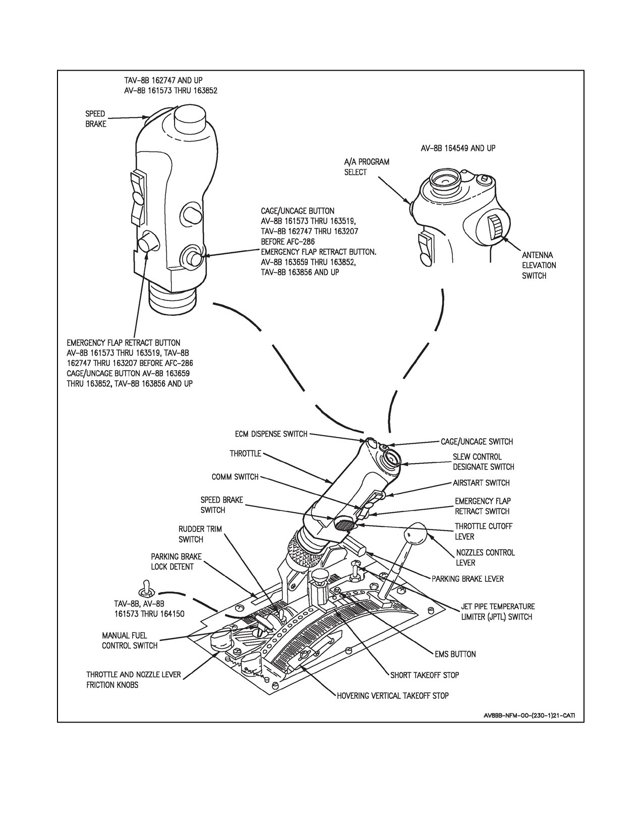
The throttle is located on the left console (Figure 2-6). The throttle is mechanically linked to the PLA and the
combined manual fuel valve and fuel shutoff cock within the FMU. When in DECS control the PLA sends an
electronic signal to the DECUs based on the position of the throttle. When the throttle is fully aft, the high pressure
fuel shutoff valve is closed and cuts off fuel supply to the engine. Forward movement to the idle rpm position opens
the shutoff valve and a ratchet stop prevents movement back except when a spring loaded throttle cutoff lever, on
the front of the throttle, is lifted. Inside the quadrant is a spring loaded full throttle stop. If the throttle is pushed hard
against this and compresses it, the jet pipe temperature limiter (JPTL) switch is switched OFF; it must subsequently
be switched ON by hand. The full throttle stop can be overridden if necessary by a push force on the throttle of 30
to 35 pounds. An interference catch ensures that the throttle lever cannot be moved past a parking BRAKE LOCK
position when the lock is engaged. A throttle damper friction control is aft of the throttle quadrant.
2.4.1.1 Rear Throttle (TAV--8B)
The rear throttle and throttle cutoff lever are linked to the forward controls and permit full engine control from the
rear cockpit. Stops and internal switches are located in the forward throttle quadrant. There is no throttle friction knob
in the rear cockpit. Throttle grip switches are the same as the forward cockpit.
2.4.2 Nozzles Control Lever
The nozzles are controlled by a lever in a quadrant inboard of the throttle, see Figures 2-6 and 2-7. If the nozzle
actuating air motor fails to move when the lever is moved, the initial 2 to 3 inches are taken up in opening the control
valve. To prevent damage to the valve (if lever movement is continued) an override spring in the control linkage starts
to compress so that a moderate force is felt. The spring will also be compressed if the air motor responds slowly to
lever movement. When the lever is fully forward against a stop at the front end of the quadrant the nozzles are fully
aft, and they rotate down as the lever is moved aft. As the nozzles are rotated down through 11° to 16° from fully
aft, a microswitch changes the JPT limiter from maximum thrust to short lift. Maximum thrust datum is reselected
as the nozzles are rotated up through 7° to 12° toward fully aft. When the lever is moved aft to the hover stop the
nozzles are set for hovering. The position of this stop gives a fuselage hovering attitude of about 6 1/2°; i.e., the
nosewheel slightly higher than the main wheels.
2-15
ORIGINAL
A1-AV8BB--NFM--000
Figure 2-6. Throttle Nozzle Quadrant
ORIGINAL
2-16
A1-AV8BB--NFM--000
Figure 2-7. Nozzles Control Mechanism
2-17
ORIGINAL
A1-AV8BB--NFM--000
The engine datum is at 1.5° to the fuselage datum. The nozzle angle for hovering is therefore 82° from the engine
datum. A nozzle braking position, at 98.5° from the engine datum, can be selected by lifting the nozzle lever over
the hover stop and pulling it back along a ramp. An adjustable short takeoff (STO) stop on the quadrant can bepreset
to allow rapid selection of nozzle angles from 35° to 75° (in 5° increments) as required, for STO or rolling vertical
takeoff (RVTO). The stop has a spring loaded control knob and is set by lifting the knob and moving the stop to the
desired position, then releasing the knob to engage the stop in a locating hole (5° increment) in the quadrant. The
selected nozzle angle is indicated on a scale alongside the stop. The STO stop can be overridden, in both directions,
by lifting the nozzle lever over the stop. When the stop is not in use it should be moved aft to a locating hole where
it is clearofthelever’s travel. A nozzlelever friction damper at the rearof thequadrant is shear wired to prevent lever
creep. If the flaps switch is in STOL, the flaps move with the nozzles. Refer to Flaps, this section. When manually
moving the nozzles during ground handling, the nozzle lever should be placed to correspond with nozzle position
so as not to damage the air motor rotary control valve.
2.4.2.1 Rear Nozzles Control Lever (TAV--8B)
The rear cockpit nozzles control lever is linked to the forward cockpit lever and provides the same control as the
forward lever. STO and vertical takeoff (VTO) stops are located only in the forward cockpit. There is no nozzle lever
friction knob on the rear cockpit.
2.4.3 STO Stop Indicator (TAV--8B)
The STO STOP indicator is located on the rear cockpit lower left main instrument panel, next to the emergency
landing gear handle. The forward cockpit STO stop setting is displayed from 35° to 75° in 5° increments. The 0° will
be displayed when electrical power is removed from the indicator or for settings below 35° and a barber pole will
be displayed for settings above 75°.
2.4.4 CMBT Switch/Light
The CMBT switch/light is on the CMBT/water panel. When the switch/light is first pressed, a green SEL light comes
on indicating combat thrust rating is operational and armed for wingborneflight. With the SEL light on, gear up, and
nozzles aft, a yellow (green on Radar and Night Attack aircraft) CMBT light comes on when JPT reaches 630 °C
with the --406 engine or 715 °C with the --408 engine. If JPT remains at or above 630 °C or 715 °C, as applicable,
for 2.5 minutes the CMBT light will flash.
Pressing the switch/light a second time disables combat thrust and turns off the light(s). If the SEL light does not come
on when the switch/light is first pressed, the combat thrust limiteris disabled and cannot be selected until thecombat
mode switch in the main wheelwell is placed to ENABLE. With the combat mode switch in DISABLE, wet and dry
rpm will be restricted to 99 percent for the --406 engine or 109 percent for the --408 engine, when above 250 knots
during thrust vector control (TVC) (nozzles greater than 11° to 17°).
Use of the full 10 minutes combat rating must be carefully monitored to prevent premature engine removal due to
count dissipation.
2.4.4.1 CMBT Switch/Light (AFT Cockpit)
The rear CMBT switch/light is on the master mode panel located on the left main instrument panel. The SEL and
CMBT lights repeat the forward cockpit SEL and CMBT light indications. The rear CMBT switch is disabled.
2.4.5 JPTL Switch
The JPTL switch when selected OFF mutes the DECS JPT limiter function. The acceleration limit corrected fan
speed, and corrected compressor speed limiting functions are retained. The AOA cutback function is not retained.
With the JPT limiter muted, the mechanical fan speed schedule is reset to the short lift wet schedule and limit. This
results in a 3.3 to 4.3 percent increase in engine rpm for the --406 engine, and a 6.0 to 7.0 percent rpm increase for
the --408 engine. Selecting limiters OFF will only result in an increase in the full throttle rpm and thrust if the engine
is actively being controlled on either a JPT limit or dry mechanical fan speed limit. If the engine is being actively
controlled on the corrected fan speed limit or the short lift wet mechanical speed limit, selecting the JPTL switch to
the OFF position will not result in an rpm or thrust increase.
ORIGINAL
2-18
A1-AV8BB--NFM--000
2.4.6 JPTL Test Switch
The JPTL test (JPTL TEST) switch, on the ground power panel, has positions of OFF, MAX and AMPL. Theswitch
is spring loaded to the OFF position. The MAX and AMPL positions are for maintenance use only and should not
be selected by the pilot.
2.4.7 Engine Fuel Control Switch
The engine fuel control (EFC) switch, located on the left console, is labeled EFC. It has positions of POS 1 and POS
2 for selecting DECU 1 and DECU 2 respectively, as the engine controlling DECU.
2.5
ENGINE DISPLAYS
Engine displays are provided by the engine display panel (EDP), head--up display (HUD), and DDI. Various warning
and caution lights are provided to notify the pilot of conditions which would hinder engine performance.
During a battery start, JPT and rpm are the only engine displays that are operative. The remaining displays will
become operative or may be selected after the main generator comes on line.
2.5.1 Engine Display Panel
The EDP is on the right side of main instrument panel. The EDP has six drum type indicators for display of reaction
control system duct pressure, fuel flow, stabilator trim position, engine rpm, jet pipe temperature (JPT), and water
quantity. A dial type indicator displays nozzle position and a green FLOW light indicates water flow.
2.5.1.1 Duct Pressure Indicator
Theductpressureindicatordisplaysreactioncontrolsystem ductpressureinpounds persquareinch.It displaysunits,
tens, and hundreds.
2.5.1.2 Fuel Flow Indicator
The fuel flow indicator displays engine fuel flow in pounds per minute. It displays units, tens, and hundreds.
2.5.1.3 Stabilator Position Indicator
The stabilator position indicator displays stabilator position in degrees nose up or nose down. It displays units and
tens on the right two drums and displays a vertical arrow pointing either up or down on the left drum.
2.5.1.4 Tachometer
The tachometer displays engine speed in percent rpm. It displays tenths, units, tens, and hundreds. A fixed decimal
point is placed between the tenths and unit drums. An ENG RPM SEL (select) switch, on the left console, selects
HI (compressor) or LO (fan) rpm display.
2.5.1.5 Jet Pipe Temperature Indicator
The JPT indicator displays JPT in °C. It displays units, tens, and hundreds. On AV--8B 165354 and up; also AV--8B
161396 through 165312, TAV--8B 162747 through 164542 after AFC--394 the JPT indicator displays 000 °C in the
event of an open thermocouple input.
2.5.1.6 Water Quantity Indicator
The water quantity indicator displays pounds of waterremaining in units often. Thetens and hundreds digits change
while the units digit is a fixed display indicating zero.
2-19
ORIGINAL
A1-AV8BB--NFM--000
2.5.1.7 Nozzle Position Indicator
The nozzle position indicator displays nozzle position in degrees. The scale is graduated in units of ten and the range
is from 0° to 120°.
2.5.1.8 Water Flow Light
Refer to Water Injection System, this chapter.
2.5.1.9 BIT Switch
Used to activate a test of the EDP. The display indicators are cycled through displayable numerals (111, 222, 333,
444, 555, 666, 777, 888 and 999) and some self--tests are done.
Note
The BIT switch can be activated in flight. This causes the MC to read JPT
as 999, flag an overtemp and start adding engine life counts.
2.5.2 Engine HUD Displays
With the HUD V/STOL mode selected, engine rpm, JPT, nozzle position and water flow are displayed on the HUD.
Engine power margin may be displayed in place of JPT and rpm. Refer to Figure 23-29.
2.5.3 Engine DDI Display
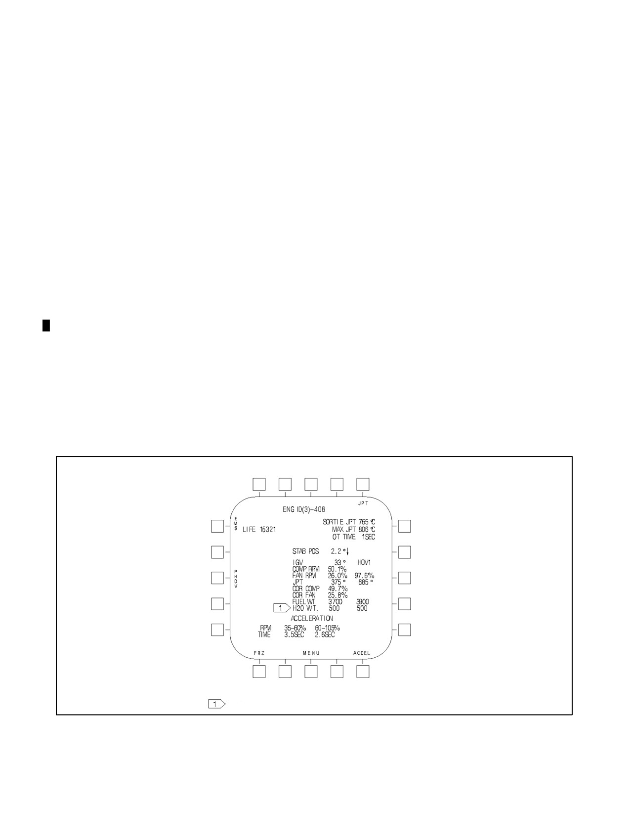
Engine displays available on the DDI include inlet guide vane angle, compressor rpm, fan rpm, corrected fan rpm,
and JPT. To select the engine display, press MENU then ENG. See Figure 2-8 for a typical engine display. The engine
identification appears at the top of the display (e.g. 406, 408 DR, 408, INVALID). Sortie JPT, maximum JPT, and
overtemperature time are displayed at the upper right and engine life count, up to 10,000 for the --406 engine and
50,000 forthe --408 engine, is displayed at theupperleft. ThesortieJPT displaysthehighestJPT forthecurrentflight
and may be reset by pressing the JPT button. The maximum JPT, overtemperature time, and engine life count are
not pilot resettable. Water quantity is shown on the engine display with H4.0.
H4.0 ONLY
Figure 2-8. Engine DDI Display
ORIGINAL
2-20
A1-AV8BB--NFM--000
Stabilator position, inlet guide vane angle, compressor and fan rpm, JPT, and fuel weight are displayed in the center.
When the FRZ button is pressed the fan rpm, JPT, and fuel weight are recorded in the hover column and the ACPT
(accept) and REJ (reject) options are enabled on the option display unit (ODU). Accepting or rejecting the data clears
the hover column until FRZ is selected again.
The acceleration time for the applicable engine rpm range is displayed at the bottom of the display. The --408 engine
display has two rpm ranges (35 to 60 percent, 60 to 105 percent) and the --406 engine display has three rpm ranges
(27 to 55 percent, 55 to 100 percent, 100 to 104 percent). The display initializes with the last acceleration times
displayed. The acceleration times are reset to 0.0 seconds by pressing the ACCEL button.
Pressing EMS button selects the incident summary display. Pressing the PHOV button selects the performance hover
checks. Refer to performance hover checks in Chapter 10 for an illustration of the display and a description of the
checks.
2.5.4 Engine Warning/Caution Lights
Theenginewarning/cautionlightsconsistoftheFIRE,OT,JPTL,andEFCwarninglightsonthewarninglightspanel
and the 15 SEC caution light on the caution light panel.
The TAV--8B and AV--8B Day Attack aircraft have the warning lights on the warning/threat lights panel and the 15
SEC caution light on the priority caution light panel. The AV--8B Radar and Night Attack aircraft warning lights are
on the warning lights panel and the 15 SEC caution light is on the caution light panel. Refer to paragraph 2.30
(TAV--8B, Day Attack aircraft) or paragraph 2.31 (Radar and Night Attack aircraft) for MASTER CAUTION and
MASTER WARNING light operation.
2.5.4.1 OT Warning Light
The OT warning light, and OT XXX legend under the airspeed box on the HUD display, comes on if the JPT exceeds
765 °C for the --406 engine or 820 °C for the --408 engine. The OT warning light goes out after the JPT is reduced
below 761 °C for the --406 engine or 816 °C for the --408 engine. The HUD OT XXX display can only be removed
by changing reject levels on the HUD control panel. On TAV--8B 163856 and up, AV--8B 163519 and up, an
OVERTEMP, OVERTEMP voice warning is provided in conjunction with the OT warning light.
2.5.4.2 JPTL Warning Light
The JPTL warning light comes on if the JPTL switch is OFF. On TAV--8B 163856 and up, AV--8B 163519 and up,
a LIMITER OFF, LIMITER OFF voice warning is provided in conjunction with the JPTL warning light. Illumination
of the JPTL warning light can signify any one of four faults:
1. JPTL switch OFF.
2. Failure of JPT limiter function within the DECU in use.
3. When illuminated in conjunction with an EFC caution, either electrical power to a DECU has been lost or a
DECU has failed and the JPT limiter has failed in the DECU in use.
4. A failure has been detected in one or more of the DECU state inputs.
A state input failure could force the controlling DECU to default to a higher or lower JPT/RPM datum, cause a rpm
fluctuation of about 3 to 5 percent, or cause the loss of the fast deceleration function on landing. Some state input
failures will show no effect to the pilot.
In the event of a JPTL warning , placing the JPTL switch to OFF will ensure full short lift wet thrust will be available
(i.e. a positive datum shift to short lift wet (SLW)).
2.5.4.3 15 SEC Caution Light (Day Attack Aircraft)
The 15 SEC caution light, on the priority caution light panel, comes on steady if the JPT exceeds the short lift
dry(SLD) or short lift wet threshold of the particular engine installed. For the --406 engine the short lift dry
2-21
ORIGINAL
A1-AV8BB--NFM--000
threshold is 687 °C and the short lift wet threshold is 705 °C. If the JPT remains at or above the threshold over 15
seconds the 15 SEC light flashes. If the JPT decreases 4° below the threshold the 15 SEC light will go out. On AV--8B
163519 and up, a FIFTEEN SECONDS, FIFTEEN SECONDS voice warning is provided in conjunction with the
15 SEC caution light. The15 SEC light is informativein natureand does not requireimmediate action from thepilot,
however, as illustrated by Figure 11-8, excessive engine life counts result if engine JPT is not reduced.
2.5.4.4 15 SEC Caution Light (TAV--8B, Radar and Night Attack Aircraft)
The 15 SEC caution light operates the same as on the Day Attack aircraft except for the threshold at which the light
comes on.
On TAV--8B 162747 through 163861 with the --406 engine installed, the 15 SEC caution light comes on steady if
the JPT exceeds the short lift dry threshold of 687 °C or short lift wet threshold of 705 °C. On TAV--8B 164113 and
up, and AV--8B Night Attack aircraft, with the --406 engine installed the 15 SEC caution light comes on steady if the
JPT exceeds the short lift dry threshold of 684 °C or short lift wet threshold of 702 °C.
On aircraft with the --408 engine installed the 15 SEC caution light comes on steady if the JPT exceeds the --408 short
lift dry threshold of 765 °C or short lift wet threshold of 780 °C.
On TAV--8B 163856 and up, AV--8B 163519 and up, a FIFTEEN SECONDS, FIFTEEN SECONDS voice warning
is provided in conjunction with the 15 SEC caution light.
The 15 SEC light is informative in nature and does not require immediate action from the pilot, however, as illustrated
by Figure 4-3, excessive engine life counts result if engine JPT is not reduced.
2.5.4.5 EFC Warning Light
The EFC warning light is located on the warning/threat panel (warning light panel for Radar and Night Attack
aircraft). The light comes on when both DECUs have failed, or if both DECUs are not powered on. On TAV--8B
163856 and up, AV--8B 163519 and up, a FUEL CONTROL, FUEL CONTROL voice warning is provided in
conjunction with the EFC warning light.
2.5.4.6 EFC Caution Light
The EFC caution light is located on the caution/advisory light panel. The light comes on when either DECU is failed
regardless of the EFC switch position or if either DECU is not powered on. On TAV--8B 163856 and up, AV--8B
163519 and up, a CAUTION, CAUTION voice warning is provided in conjunction with the EFC caution light. The
EFC caution light will come on momentarily when the EFC switch position is changed.
2.5.5 Engine Ventilation and Fire Warning System
The engine bay is divided into three ventilated zones. An engine mounted fireproof bulkhead separates zone 1 from
zone 2. Zone 1 contains the engine compressor section, fuel system and accessories. Zone 2 contains the engine
combustion, turbine and exhaust sections. Zone 3 is located beneath the fuselage heat shield in zone 2 and contains
the reaction control system butterfly valveand ducting. Zones 1 and 2 are ventilated by ram air intakes at theforward
end of the front nozzle fairings and at the wing roots. This airflow is assisted by a continuous flow inducer nozzle
(supplied by engine fan bleed air) which provides ventilation during ground or vertical flight operation. Zone 3 is
also ventilated by engine fan bleed air supplied by the flow inducer nozzle. A continuous fire sensing element is
routed through zones 1 and 2, and a separate element is routed through zone 3. Both elements are connected to a single
control unit. The elements sense heat around the engine, engine accessories, reaction control system butterfly valve
and ducting, and the jet pipe. A FIRE warning is activated if a preset temperature is exceeded. System continuity can
be checked by placing the compass/lights test switch to LTS TEST and noting that the FIRE warning light comes
on. Two red fire access spring--loaded panels, one on each side of the fuselage above the engine give access to zone
1 for fire fighting equipment. Access to zone 2 is gained via the ventilation ducts at the leading edge of the wing roots.
2.5.5.1 FIRE Warning Light
The FIRE warning light, on the right main instrument panel, comes on if a fire condition is sensed in any of the engine
bay zones. On TAV--8B 163856 and up, AV--8B 163519 and up, an ENGINE FIRE, ENGINE FIRE voice warning
is provided in conjunction with the FIRE warning light.
ORIGINAL
2-22
A1-AV8BB--NFM--000
2.6
GAS TURBINE STARTER/AUXILIARY POWER UNIT
The gas turbine starter/auxiliary power unit is used to start the engine or drive the APU generator. It consists of a gas
generator, a free power turbine, reduction gear train, an ignition system, an electric starter motor, and electrical
circuits for automatic control. Fuel for the GTS is supplied by the aircraft fuel system. With the battery switch in
BATT, the electric starter motor is energized by placing the engine start switch to the electrically held ENG ST
position which engages the GTS output shaft to the engine. The GTS ignition and fuel control systems areautomatic
and the GTS starts and accelerates to operating speed within 25 seconds. When the engine attains self--sustaining
speed, the GTS automatically disengages and the engine start switch returns to OFF. If the GTS does not reach
operatingspeedwithin25secondsorthemainengineisnotself--sustainingwithin40seconds,theGTSautomatically
shuts down and the engine start switch returns to OFF. If the GTS is operating in the APU mode (APU generator
operating), engine start is accomplished by placing the engine start switch to ENG ST. In this condition, the APU
generator drops off the line, the APU switch automatically returns to OFF, the 40 second GTS shut down protection
circuit is activated and the main engine is automatically engaged for start. The APU advisory light comes on whenever
GTS/APU operation is selected and the APU is ready to accept an electrical load. For APU mode operation, refer
to APU, Electrical Power Supply System.
2.7
FUEL SYSTEM
Thefuel system (seeAircraft and EngineFuel System, foldout section)consists ofseven integral tanks (fivefuselage
tanks and two internal wing tanks). Provisions are made for four externally mounted (droppable) tanks. The tanks
are divided into two feed groups: the left feed group consists of the left external tank(s) (when installed), left internal
wing tank, left and right front tanks and the left center feed tank. The right feed group consists of the right external
tank(s) (when installed), right internal wing tank, rear tank and right center feed tank. A retractable air refueling probe
may be installed for air refueling. Tank pressurization, by regulated engine bleed air, transfers fuel from the tanks
of the left and right groups to their respective center feed tank, where fuel pressure to the engine is then increased
by a boost pump in each feed tank and a fuel flow proportioner. The aircraft is fueled by using single point ground
fueling. There are no gravity fueling provisions made for the internal or external fuel tanks. All tanks have fuel gaging
probes which provide fuel quantity indications (in pounds) to the fuel quantity indicator. Each center feed tank is
equipped with a refueling valve. The refueling valve can be manually selected to the open or closed position by the
air refueling (A/R) switch on the cockpit fuel control panel. The refueling valve is automatically closed when the high
fuel level thermistor, in each internal wing tank, senses a full condition. External tanks also contain a high fuel level
thermistor which overrides the thermistor in their respective internal wing tank. With four external tanks installed,
the outboard external tanks will override both internal wing and inboard external tanks. On the ground, the external
tanks can be locked out to prevent refueling. Fuel may be dumped from the external and internal wing tanks.
2.7.1 Fuel Shutoff Handle
The fuel shutoff handle (fwd cockpit only) has positions of ON and OFF and is located on the left wall just aft of the
left console. When the handle is OFF, the aircraft fuel system is isolated from the engine and the fuel flow proportioner
is shut off. The handle can be moved down to the ON position where it will be locked. A button on the end of the
handle must be pressed to release the ON lock.
2.7.2 Engine Driven Fuel Pumps
There are two engine driven fuel pumps in the fuel control unit. One is an impeller type backing pump and the other
is a gear type main pump. The main pump is driven by the engine high pressure compressor shaft and the backing
pump is driven by the main pump through an interconnecting shaft. The backing pump receives fuel from the fuel
boost pumps via the fuel flow proportioner and then pumps this fuel to the inlet side of the main pump by way of
a low pressure fuel filter.
On the --406 and --408A engines, a tapping down stream of the low pressure fuel filter supplies fuel (to be used as
a hydraulic medium) to the IGV control unit. Fuel from the control unit is returned to upstream ofthe backing pump.
On the --408B engine, a tapping down stream of the main pump supplies fuel to the HMU of the EVICS. Fuel is
returned to upstream of the backing pump.
2-23
ORIGINAL
A1-AV8BB--NFM--000
The output of the pumps always exceeds engine demand and delivery is controlled by a mechanical pressure drop
regulator which is sensitive to HP rpm. Excess pump supply fuel is bypassed to upstream of the backing pump. A
pump pressure relief valve is in the bypass line.
If the flow proportioner and both boost pumps fail or are turned off at the same time, tanks pressurization will maintain
fuel flow through the inoperative pumps and the flow proportioner bypass valves to the engine driven pumps, to
enable engine operation.
2.7.3 Fuel Transfer System
Fuel transfer is automatic anytime the engine is running. Fuel transfer is normally accomplished by utilizing regulated
sixth stage engine bleed air to pressurize the fuel tanks. Pressure is applied to, and transfer starts from, the outboard
external tanks to the inboard external tanks (if installed) to the internal wing tanks and from them to the left and right
front tanks (left feed group) or the rear tank (right feed group). From the front and rear tanks, fuel transfers to the
respective, left or right, center feed tank where a boost pump supplies the engine via the flow proportioner.
Pressurization can be shut off simultaneously in both groups by placing the air refueling switch, on the left console,
to OUT. In this event, or if pressurization fails in either group, transfer will continue due to suction developed by the
boost pump(s). While pressurization is operating, fuel is transferred to each center tank, in series from all tanks in
the group, at the same rate at which fuel is being consumed from that tank. If pressurization is off and external tanks
are installed, the transfer rate from the external tank(s) to the internal wing tank in each group may not equal the rate
offuelconsumptionfromthatgroupandtheinternalwingtankfuelquantityindicationmayshowadecrease.Transfer
from the external tanks can be verified by monitoring external tank fuel quantity. Transfer into the center tanks can
be verified by monitoring feed quantity.
2.7.3.1 External Fuel CG Control
The external tanks are divided into three compartments to control center of gravity (cg) during fuel transfer or
refueling. Fuel first transfers from the aft compartment, then the forward compartment followed by the center
compartment. During refueling, the compartments fill in the reverse order.
2.7.3.2 Pressurization and Vent System
Sixth stage compressor bleed air pressurizes the system and transfers the fuel. The air enters the system through a
check valve, a filter and two pressure control valves (one for each feed group). The control valve regulates tank
pressure, provides vacuum relief when pressurization is off, and vents the tanks to atmosphere during ground or air
refueling. Pylon fuel air valve(s), in each inboard and intermediate pylon, allow fuel and air to be transferred from
the external tank(s) to the internal wing tank(s). When external tank(s) are jettisoned, a spring loaded poppet valve,
in the pylon fuel airvalve, allows pressurized airto continueto pressurizethe respectivetank group. A float operated
vapor release valve in each feed tank dissipates air or vapor pressure to atmosphere, thereby preventing pressure in
the feed tanks from building up and stopping fuel transfer. If feed tank pressure becomes excessive, the valve opens
and discharges air (or fuel) regardless of float position. During negative g flight, weighted arms hold the valves closed
to prevent fuel loss.
2.7.3.3 Transfer Caution Lights (L or R TRANS)
There are two TRANS caution lights located on the caution light panel. When illuminated, these L TRANS and R
TRANS lights indicatethat thefuel pressureat theinlet totherespectivecenterfeedtank hasdropped toapointwhere
fuel transfer into the center tank may be insufficient. When pressurization is ON (air refueling switch at IN or PRESS)
the pressure is regulated so that sufficient flow of pressurized fuel is transferred to the feed tanks. After pressurization
is OFF (either or both control valves failed closed or air refueling switch at OUT), either or both lights will come
on, independently, as the residual pressure in the tanks decreases in a period of timedependent upon the fuel quantity
and tank pressure (when pressurization was stopped) and the rate of fuel consumption. This may or may not occur
within the flight endurance of the fuel remaining, but as long as the TRANS lights are off the fuel flow into the feed
tanks is sufficient for any engine power demand. With the air refueling switch at OUT, and prior to actual refueling,
the TRANS lights may come on but should go out soon after refueling begins.
ORIGINAL
2-24
A1-AV8BB--NFM--000
2.7.3.4 Tanks Overpressurized/Overtemperature Warning Light (L or R TANK)
A L and R TANK warning light is located on the master warning lights panel and indicates that the pressure in the
corresponding feed group is approaching a level where structural damage to the tank may occur or that the bleed air
temperature is above a safe temperature level (i.e., near the flash point temperature of the fuel). If either light comes
on, pressurization is automatically shut off for the corresponding feed group provided the air refueling (A/R) switch
is in the IN position. On TAV--8B 163856 and up, AV--8B 163519 and up, a LEFT TANK, LEFT TANK or RIGHT
TANK, RIGHT TANK voice warning is provided in conjunction with the L or R TANK warning light.
2.7.4 Fuel Boost System
Fuel is supplied to the engine by either ac powered or dc powered electrical boost pumps and a hydraulically driven
fuel flow proportioner. The proportioner ensures that equal amounts of fuel are consumed from each feed tank. If both
boost pumps fail, the flow proportioner (acting as a hydraulically driven pump) will continue to supply fuel to the
engine. If the proportioner fails, the fuel levels will probably go slowly out of balance. In this case, the boost pump
associated with the low level should be shut off until balance is regained. If the main generator fails or the ac boost
pump(s) fails, the dc powered boost pump(s) may be selected for inflight emergency operation.
2.7.4.1 Boost Pumps
There are four electrically operated boost pumps, two in the lower portion of each center feed tank. The two pumps
ineachcenterfeedtankarecontainedinasinglehousing,oneisacpoweredandtheotherisdcpowered.Exceptduring
start, the ac powered pumps normally supply fuel to the engine. During ground engine start, only the right dc pump
supplies fuel to the engine. After the engine reaches self--sustaining rpm, the right dc pump drops off line and both
ac pumps supply fuel to the engine, providing the main generator is on line and the boost pump switches are in
NORM. Each pump is enclosed in a negative g chamber for limited inverted flight. At maximum power and with
at least 300 pounds of fuel in each feed tank, approximately 15 seconds of fuel is available to the boost pumps during
negative g flight. A L or R PUMP caution light, on the caution light panel, comes on any time the associated pump
output pressure is below acceptable limits. The ac driven pumps only operate with the main generator on line or
external electrical power applied. The dc driven pumps will operate with external power, main generator, emergency
generator, or battery. Both dc powered pumps are automatically ON when the airstart button is pressed.
2.7.4.2 Fuel Flow Proportioner
The function of the fuel flow proportioner is to equalize the flow of fuel from the two feed groups. The proportioner
consists of two equal capacity vane type pumps with a common drive from a hydraulic motor. The hydraulic motor
is driven by HYD 1 system pressure and is controlled by mechanically and electrically operated, shutoff valves. The
mechanical valve is connected to the fuel shutoff valve and prevents the proportioner from operating whenever the
fuel shutoff valve is closed. The electrical valve is controlled by the FUEL PROP switch on the left console. The valve
is energized closed and deenergized open. The switch provides a means of shutting off the proportioner if a fuel out
of balance correction is needed. If the proportioner fails or is turned off, the boost pumps will continueto supply fuel
to the engine via bypass passages, with check valves, around the pumping elements of the proportioner. Whenever
the flow proportioner is inoperative, the fuel quantities in the two tank groups may slowly go out of balance. In this
event, the boost pump in the tank group with the lowest quantity should be shut off until balance is regained. During
thisperiod, theonly fuelflow totheengineis fromthetankgroup withtheoperatingboost pump.Fuel balanceshould
be maintained for the following reasons:
1. To prevent excessive lateral unbalance of the aircraft with fuel in the internal and external tanks.
2. To maintain the aircraft center of gravity within longitudinal limits after the wing tanks are empty.
3. To prevent one feed tank from becoming empty before the other.
A PROP caution light, on the caution light panel, comes on if the proportioner fails or is shut off electrically. If the
electrical power supply to the PROP switch fails, the proportioner will come ON regardless of the switch position.
2-25
ORIGINAL
A1-AV8BB--NFM--000
2.7.4.3 Fuel Prop Switch (TAV--8B)
The modified fuel prop switch, in the front cockpit, on the left console fuel panel has OFF, AUTO, DL (dual), and
RT (right) positions. Normal operating position of the fuel proportioner switch is AUTO. The front cockpit pilot can
manually balance the fuel by positioning the prop switch to DL or RT feed which operates the crossfeed valve or by
placing the prop switch to off and turning off one of the pump switches.
The fuel prop switch in the rear cockpit is on the left console miscellaneous switch panel and allows the rear pilot
to disable the automatic fuel proportioner by securing the proportioner.
2.7.4.4 Crossfeed Valve (TAV--8B)
Duetothespacerequiredbytheaftcockpit,theleftfuelgroupwasreducedbyapproximately450pounds.Acrossfeed
valve has been added to the fuel system of the TAV--8B to compensate for the fuel imbalance in order to maintain
cg limits. This valve has two positions, DUAL and RIGHT. In the DUAL position, the valve does not affect fuel
system operation. In the right feed position, the valve allows fuel flow from the right fuel group only. The crossfeed
system is spring loaded to the dual position if a failure occurs. The crossfeed valve is automatically controlled by
level sensors when the prop switch is in the AUTO position. Sensors in the left feed group energize the valve to the
right feed position when the fuel level in the left feed group is sensed to be less than approximately 300 pounds ±50.
Sensors in the right feed group energize the valve to the dual feed position when fuel is sensed to be less than
approximately 300 pounds ±50 in the right feed group.
2.7.4.5 Fuel Crossfeed Indicators (TAV--8B)
The R FEED advisory light, on the caution and advisory light panel, will be on when the crossfeed valve is in the
RT feed position. The advisory light will be off when the crossfeed valve is in the DL feed position. With the Prop
Switch in the AUTO position the advisory light will illuminate when the left fuel group senses less than
approximately 300 pounds ±50 and the crossfeed valve is in the right feed position. The advisory light will remain
on until the sensors in the right fuel group sense less than approximately 300 pounds and return the crossfeed valve
back to the DUAL position. The advisory light should not illuminate when the Prop Switch is in the DL or OFF
position.
The R FEED warning light indicates automatic control of the crossfeed valve has failed and the valve is in the
incorrect position. Three situations can result in this warning light. In all situations, placing the Fuel Quantity
Indicator to FEED and checking the fuel quantity remaining in the feed tanks will determine subsequent required
actions. The fuel quantity will require monitoring.
1. R FEED warning with less than 300 pounds in the left feed tank and 300 pounds or greater in the right fuel
system — set the fuel proportioner switch to RT and check the R FEED advisory light comes on and the R
FEED warning light goes out.
2. R FEED warning with both feed tanks full, 300 pounds in each fuel system — set the fuel proportioner switch
to DL and verify the R FEED warning and advisory lights go out.
3. R FEED warning light with both right and left feed tanks indicating less than 300 pounds — set the fuel
proportioner switch to OFF and verify the R FEED warning and advisory lights go out.
2.7.5 Wing Fuel Dump
External and internal wing fuel may be dumped in flight by selecting the DUMP position on the wing fuel dump
switches. There are two electro--magnetically held switches, on the left console, marked L (left) and R (right). Both
switches may be used simultaneously (to reduce gross weight) or individually (to correct out of balance conditions).
When dump is selected, a motor operated valve opens, and fuel is dumped overboard through fuel dump outlets. The
fuel is forced out of the wing tanks by normal transfer pressure. Fuel continues to dump until the internal wing tanks
are empty, the switches are placed to NORM, or if BINGO is set above fuselage fuel quantity, to the fuel setting in
the BINGO window. Time required to empty a full wing tank in level flight is approximately 5 minutes.
2.7.6 Fuel Low Level Indicating System
The fuel low level indicating system is completely independent of the fuel quantity indicating system. Each feed
group has a (L or R) FUEL caution light on the priority caution light panel. When the internal fuel level in either feed
ORIGINAL
2-26
A1-AV8BB--NFM--000
group drops to between 700 and 800 pounds of actual fuel (110 gallons), the corresponding (L or R) FUEL caution
lightilluminatessteadyandthedigitalfuelquantityindicatorwill indicate750 ±250pounds withINT selected.When
the internal fuel level in either feed group drops to between 200 and 300 pounds of actual fuel (37 gallons), center
feed tank only, the corresponding (L or R) FUEL caution light flashes and the digital fuel quantity indicator will
indicate 250 ±100 pounds with FEED selected. On TAV--8B 163856 and up, AV--8B 163519 and up, a FUEL LOW
LEFT, FUEL LOW LEFT or FUEL LOW RIGHT, FUEL LOW RIGHT voice warning is provided in conjunction
with the flashing L or R FUEL caution light.
2.7.7 Fuel Quantity Indicating System
The fuel quantity indicating system provides readings, in pounds, of usable feed group and usable total fuel. Figure 2-9
shows the actual fuel quantity in each tank when fully serviced including non--usable fuel.
2.7.7.1 Fuel Quantity Indicator
The fuel quantity indicator is on the right main instrument panel. It has four display windows, a BINGO set knob,
a seven--position selector switch, and an ON/OFF indicator. The window labeled TOT, continuously displays total
usable fuel in increments of 100 pounds. The windows labeled L and R, display left and right usable fuel in the
corresponding feed group in increments of 50 pounds. The window labeled BINGO displays the set fuel quantity that
activates the BINGO caution light. The BINGO set knob is used to set the BINGO window in increments of 100
pounds. The selector switch provides individual tank monitoring of the left and right feed groups and a built--in--test
(BIT) of the indicator. The ON/OFF indicator displays the word ON if the indicator is on or OFF if it is off.
2.7.7.2 Fuel Quantity Selector Switch
BIT - A spring loaded position that starts built--in--test of the system.
FEED - Fuel remaining in respective center feed tank is displayed.
TOT - Total fuel remaining in respective feed group is displayed.
INT - Fuel remaining in internal tanks of respective feed group is displayed.
WING - Fuel remaining in respective internal wing tank is displayed.
INBD - Fuel remaining in respective inboard external tank is displayed.
OUTBD - Fuel remaining in respective outboard external tank is displayed.
Thefuel quantityselectorswitchshould beplaced tothepositionthat bestdescribes theaircraft state.Ifexternaltanks
are used, the TOT position will present the most accurate fuel indication. With internal fuel only, the INT position
is more accurate and should be used. When aircraft total fuel is below 750 pounds, the FEED position will most
accurately indicate the fuel remaining in the respective center feed tank.
2.7.7.3 Bingo Caution Light
ABINGO caution light, on the left main instrument panel, comes on within ±200 pounds of apreset valuecontrolled
by the pilot. An adjustable fuel quantity display on the fuel quantity indicator may be set to any level up to 9,900
pounds. If BINGO is set above 2,800 and fuel dump is selected, fuel dumping will stop when the BINGO caution
light comes ON. On TAV--8B 163856 and up, AV--8B 163519 and up, a BINGO, BINGO voice warning is provided
in conjunction with the BINGO caution light.
2.7.7.4 Load Caution Light
The LOAD caution light on the caution light panel comes on if lateral fuel asymmetry exceeds 103,000 ±20,000
inch--pounds.
2.7.7.5 BIT Display
When BIT is selected, the fuel quantity indicator displays 1400 ±100 in the L window, 2400 ±100 in the R window,
3800 ±200 in the TOT window, the L and R FUEL low level cautions flash, the LOAD and MASTER caution lights
come on and if the BINGO fuel is set above 4,000 the BINGO light comes on. LEFT and RIGHT full advisory lights
(on the windshield arch) will also flash during BIT.
2-27
ORIGINAL
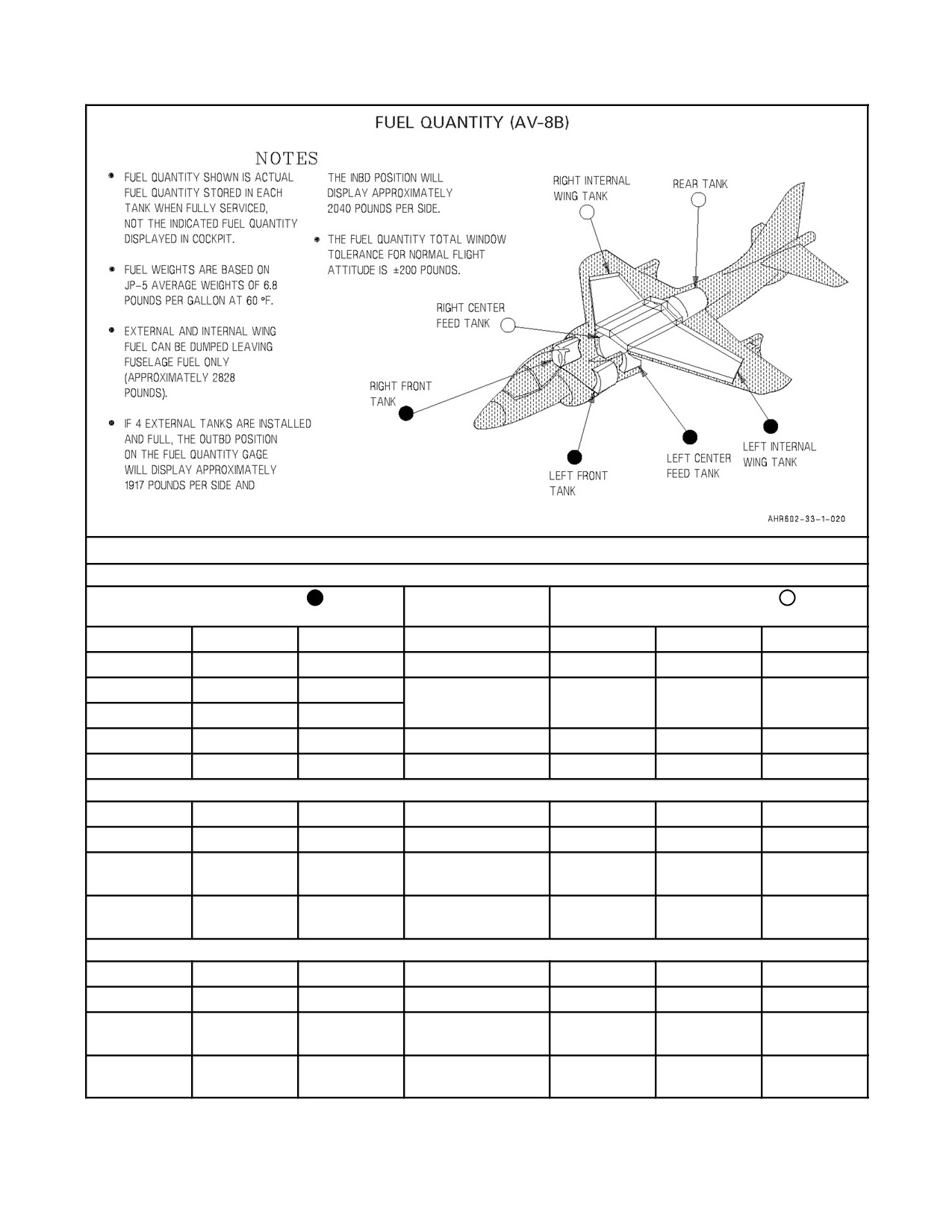
A1-AV8BB--NFM--000
INTERNAL FUEL WITHOUT EXTERNAL TANKS
LEFT FEED GROUP ONLY
LEFT AND RIGHT
RIGHT FEED GROUP ONLY
FEED GROUPS
GALLONS
TANK
POUNDS
POUNDS
POUNDS
TANK
GALLONS
47
Center feed
320
640
320
Center feed
47
80.5
Left front
547
2,188
1,094
Rear
161
80.5
Right front
547
362.5
Internal wing
2,465.5
4,931
2,465.5
Internal wing
362.5
570
Total
3,879.5
7,759
3,879.5
Total
570.5
INTERNAL FUEL PLUS 2 EXTERNAL TANKS
374
Internal wing
2,543
5,086
2,543
Internal wing
374
582
Total internal
3,957.5
7,915
3,957.5
Total internal
582
282
At station 2
1,917
3,834
1,917
At station 5
282
or 3
or 6
860
Total internal
5,874.5
11,749
5,874.5
Total internal
860
plus external
plus external
INTERNAL FUEL PLUS 4 EXTERNAL TANKS
374
Internal wing
2,543
5,086
2,543
Internal wing
374
582
Total internal
3,957.5
7,915
3,957.5
Total internal
582
582
At station 2
3,957.5
7,915
3,957.5
At station 5
582
and 3
and 6
1,164
Total internal
7,915
15,830
7,915
Total internal
1,164
plus external
plus external
Figure 2-9. Fuel Quantity (Sheet 1 of 2)
ORIGINAL
2-28
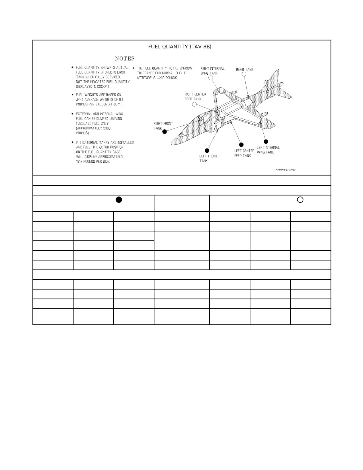
A1-AV8BB--NFM--000
INTERNAL FUEL WITHOUT EXTERNAL TANKS
LEFT FEED GROUP ONLY
LEFT AND RIGHT
RIGHT FEED GROUP ONLY
FEED GROUPS
GALLONS
TANK
POUNDS
POUNDS
POUNDS
TANK
GALLONS
47
Center feed
320
640
320
Center feed
47
46
Left front
312.8
1,719.6
1,094
Rear
161
46
Right front
312.8
362.5
Internal wing
2,465.5
4,931
2,465.5
Internal wing
362.5
501.5
Total
3,411.1
7,290.6
3,879.5
Total
570.5
INTERNAL FUEL PLUS 2 EXTERNAL TANKS
374
Internal wing
2,543.2
5,086.4
2,543.2
Internal wing
374
513
Total internal
3,489
7,447.2
3,958.2
Total internal
582
282
At station 2
1,917.6
3,835.2
1,917.6
At station 6
282
795
Total internal
5,406.6
11,282.4
5,875.8
Total internal
864
plus external
plus external
Figure 2-9. Fuel Quantity (Sheet 2)
2.8
AIR REFUELING SYSTEM
A retractable air refueling probe may be installed above the left air inlet. A discussion of the aerodynamic effects of
the refueling probe can be found in paragraph 11.4.5.2 of this manual. The probe is extended and retracted using
HYD 1 pressure. An A/R switch, READY light, and LEFT and RIGHT light provides control and indications for
theairrefueling system. At night theprobe and drogue areilluminated by a probelight. Aftercontact, refueling stops
after all tanks are full. Refueling can also be stopped by withdrawing the probe from the drogue.
2.8.1 READY Light
The READY light is on the windshield arch. When the A/R switch is placed to OUT, the READY light comes on
after the probe extends and locks. When refueling begins, the light goes out. After refueling, the light comes on and
stays on until the A/R switch is placed to IN and the probe is fully retracted and locked. The light should not be on
with the A/R switch in PRESS.
2-29
ORIGINAL
A1-AV8BB--NFM--000
2.8.2 A/R Switch
The A/R switch (air refueling) is on the left console. The switch is lever--locked and has positions of IN, OUT and
PRESS.
IN - Retracts the probe and pressurizes the tanks.
OUT - Stops pressurizationto thetanks andextends A/Rprobeifinstalled. Aftercontact ismadeandrefueling
begins the tanks depressurize.
PRESS - Leaves the probe extended and pressurizes the tanks. In this position, the automatic pressurization
shut off associated with the L or R TANK warning lights is deactivated.
2.8.3 LEFT and RIGHT Full Advisory Lights
The LEFT and RIGHT full advisory lights are on the windshield arch. On a clean aircraft or when only two external
tanks are installed, each light flashes when its corresponding feed group is full. However, when four external tanks
are installed, the LEFT or RIGHT light comes on steady when the corresponding inboard external tank is full, then
flashes when the feed group is full. The lights should not be on with the A/R switch set to IN or PRESS.
2.8.4 Air Refueling Probe Light
An air refueling probe light is installed on the probe. The light is used during night air refueling to illuminate the
refueling probe and drogue. The light is controlled by a probe in limit switch. When the probe is extended, the air
refueling probe light automatically comes on (provided the exterior master lights switch is in EXT LT).
2.8.5 Air Refueling/Dump System
The pilot can dump external and internal wing fuel only, leaving fuselage fuel of approximately 2,828 pounds for
the AV--8B and 2,360 pounds for the TAV--8B. On TAV--8B the rear pilot cannot dump fuel or configure the aircraft
for air refueling.
2.8.6 Fuel Quantity (TAV--8B)
The left and right front tanks size has been reduced in the TAV--8B. Refer to Figure 2-9 for TAV--8B fuel quantities.
2.9
GROUND REFUELING SYSTEM
The aircraft can be refueled on the ground through a standard refueling/defueling pressure coupling. Refer to
A1--AV8BB--NFM--600.
2.10
ELECTRICAL POWER SUPPLY SYSTEM
The electrical power supply system consists of a main generator, an emergency generator
(APU), two
transformer--rectifiers, a battery, and a power distribution (bus) system. External electrical power can be applied to
the bus system on the ground. On --408B engines, a permanent magnet alternator integral to the HMU provides
electrical power supply for the IDEC and LANE 2 DECU. See Electrical System, foldout section, for electrical
system simplified schematic.
2.10.1 AC Electrical Power
AC electrical power is supplied by a main generator or an emergency generator (APU). During normal operation the
main generator powers the entire electrical system. The APU acts as a backup for the main generator and will power
the critical buses after main generator failure. The APU can be operated in a standby mode whereby the APU
automatically comes on the line after the main generator fails or it can be selected on after main generator failure.
The APU is also used during ground alert to recharge the battery.
2.10.1.1 Main Generator
On TAV--8B 162747 through 163861, AV--8B 161573 through 163852, the main generator is an engine driven
15/20 KVA variable speed constant frequency generator which supplies 115/200 volt, 3 phase, 400 Hz alternating
current to the aircraft main and essential ac buses, and to the main and standby transformer--rectifiers. On TAV--8B
164113 and up, AV--8B 163853 and up, the main generator output is increased to 30 KVA. The generator is cooled
ORIGINAL
2-30
A1-AV8BB--NFM--000
by oil from an oil cooler independent of the engine oil system. The generator is activated automatically when the
generator switch is in the GEN position, and the generator is connected to the bus system when voltage and frequency
are within prescribed limits (approximately 23 percent engine rpm). A green GEN light and a push--to--test button
are located under an access panel on the forward left fuselage. When the push--to--test button is pressed and the light
comes on, the main generator oil level is satisfactory. A protection system within the generator control unit protects
against damage due to undervoltage, overvoltage, over and under frequency, and feeder faults. If a fault or
malfunction occurs the control circuits remove the generator from the bus system. The generator control switch must
be cycled from GEN to OFF and back to GEN to bring the generator back on the line after the fault or out--of--tolerance
condition occurs. For an underspeed fault, the generator will come back on the line without cycling the generator,
provided the underspeed condition is corrected. The generator may be removed from the bus system at any time by
placing the generator control switch to OFF.
2.10.1.1.1 Generator Warning Light
A generator warning light, labeled GEN, is on the warning/threat lights panel on the instrument panel. The light
comes on whenever the main generator is off the line. On TAV--8B 163856 and up, AV--8B 163519 and up, a
GENERATOR, GENERATOR voice warning is provided in conjunction with the GEN warning light. On Radar and
Night Attack aircraft, the light operates in conjunction with the MASTER WARNING light.
2.10.1.1.2 Generator Control Switch
The generator control switch is on the electrical panel on the forward right console.
GEN - Allows main generator to come on the line when all conditions are correct.
OFF - Removes main generator from the line. Position is also used when cycling generator protective
functions after a malfunction to allow reset.
TEST - Position used for ground test (not operative).
2.10.1.2 Auxiliary Power Unit
A6KVAemergencygenerator,referredtoastheAPU,isinstalledasabackupforthemaingenerator.TheAPUis
driven by the GTS, provided the GTS is operating in theAPU mode; that is, the GTS is not being used to start the
aircraftengine.WiththebatteryswitchtoBATTandtheenginestartswitchtoOFF,placingtheAPUgeneratorswitch
toONwillstarttheGTStodrivetheAPU.TheAPUwillthenpowerallofthebusesintheelectricalsystem,except
forthemain 115 volt acand themain 28 volt dcbuses, provided themaingeneratorisofftheline. TheAPU canbe
operated in a standby mode by turning it on whileon theground orin theair with the main generator operating. If
the main generator then drops off the line the APU automatically comes on the line. If the main generator is then
restoredtotheline,theAPUwillreverttostandbystatus.IftheAPUisturnedonbeforetakeoffandthemaingenerator
isoperating,theAPUwillautomaticallyshutdownwhentheaircraftreaches325knots.IftheAPUisturnedonwhile
airborne,thereisnoautomaticshutdownspeedunlesstheWOWswitchiscycled(i.e.,afteralanding).IftheAPU
modeisselectedandtheenginestartmodeisthen selected,atranslationstart willbemadeand theAPU modewill
be terminated. The APU mode may be re--selected after theengine start mode is terminated. TheAPU modemay
be re--selected after the engine start mode is terminated. APU control circuits contain protection circuits which
preventtheAPUfromcomingonthelineinthepresenceofovervoltage,overfrequency,andunderfrequency.Should
afaultoccurandcausetheAPUtotripofftheline(theessentialacbuscontactorsdeenergizingandAPUGENcaution
lighton),theAPUcanbebroughtbackonthelineifthefaultclearsbyplacingtheAPUgeneratorswitchmomentarily
to the RESET position.
The APU is used during ground alert to recharge the battery. Before the dc voltmeter indicates 24.5 volts or below,
the APU is turned on by placing the battery switch from ALERT to BATT and then placing the APU GEN switch
to ON. After charging, placing the APU GEN switch back to OFF turns off the APU.
On radar aircraft, with weight--on--wheels, a load shed function decreases the power requirements when operating
on APU power. Systems not powered because of load shed are the radar warning receiver (RWR), TACAN, and
exterior lights (except taxi lights and side slip vane lights).
2.10.1.2.1 APU Caution/Advisory Lights
Two lights on the caution/advisory lights panel are associated with operation of the APU. The APU GEN caution
light comes on whenever the emergency generator system malfunctions with the APU on. Upon initial selection of
2-31
ORIGINAL
A1-AV8BB--NFM--000
the APU, a 16 second delay is provided in the light circuit to allow the gas turbine system and emergency generator
system time to stabilize. The APU advisory light comes on whenever the GTS is operating in either the engine start
or APU mode. On AV--8B 163659 and up, TAV--8B 163856 and up, also AV--8B 161373 through 163519, TAV--8B
162747 through 163207 after AFC--329, the APU advisory light comes on only when the APU is ready to accept an
electrical load.
2.10.1.2.2 APU Generator Switch
The APU GEN switch on the electrical panel controls operation of the APU.
ON - With battery switch in BATT, GTS drives the APU provided it is not in the engine start mode.
RESET - Momentary position allows generator protective functions to reset.
OFF - Terminates GTS/APU operation.
2.10.2 DC Electrical Power
Two transformer--rectifiers (TRUs) and a battery are provided. The TRUs convert 3 phase 115 volt ac power from
either the main or the emergency generator to 28 volt dc power. The main TRU is rated at 200 amperes and the standby
TRU is rated at 50 amperes. With the main generator operating and the battery switch in BATT, the main TRU
provides power to all dc buses, except the ground service and switched battery buses which are powered by the
standby TRU. With the main generator off the line and APU on the line, the main, armament, master arm 28 volt dc
buses automatically disconnect from the main TRU and become deenergized. Should the main TRU fail, the main,
armament, master arm and essential 28 volt dc buses are deenergized, and the standby TRU assumes operation of
thejett, emergency, and alert 24/28 volt dcbuses afterashort timedelay. Should thestandby TRU fail, the main TRU
assumes operation of the switched battery and ground service 24/28 volt dc buses after a short time delay, and thus
powers all of the dc buses. The 24 volt lead acid battery is connected directly to the ground service 24/28 volt dcbus.
With the battery switch in BATT, the ground service bus is connected to the switched battery bus and the battery is
charged by the standby TRU. If the standby TRU fails the battery is charged by the main TRU. Should both TRUs
(or both generators) fail the following buses are powered by the battery for a limited time with the battery switch in
BATT: ground service, switched battery, jett, alert, and emergency 28 volt dc buses. With the battery switch in
ALERT, the battery connects to the alert 24/28 volt dc bus in addition to the ground service 24/28 volt dc bus. In
ALERT, the battery is isolated from both TRUs and will completely discharge unless periodically charged by placing
the battery switch to the BATT position with a generator and TRU operating.
2.10.2.1 DC Caution Light
Failure of the main TRU is indicated by the DC light on the caution/advisory lights panel coming on. The light
operates in conjunction with the MASTER CAUTION light.
2.10.2.2 STBY TR Caution Light
Illumination of the STBY TR caution light indicates that the standby TRU is off the line and is not charging the
battery. The light operates in conjunction with the MASTER CAUTION light. With the battery switch in BATT and
the standby TRU output below 24.75 volts for a period of greater than 3.5 seconds, the STBY TR light comes on.
During GTS start thestandby TRU is temporarily tripped offthelineand is prevented from coming on thelineduring
the start, and the STBY TR light comes on.
2.10.2.3 DC Voltmeter
A dc voltmeter on the electrical panel indicates voltage on the alert 24/28 volts dc bus. The voltmeter indicates battery
voltage when the battery switch is in ALERT and emergency dc bus voltage when the battery switch is in BATT. The
most accurate indication of battery condition is with generators off and the battery switch in BATT.
2.10.2.4 DC Test Switch
A DC test switch on the electrical panel is used to check operation of the system by simulating failure of either the
main or standby TRU. The switch travels inboard/outboard, rather than fore and aft, when it is actuated. The DC test
switchcanbelatchedinanyofitsthreepositions andused, inflight, torecoverfrommost EmergencyDC Busfailures
(see paragraph 15.14).
ORIGINAL
2-32
A1-AV8BB--NFM--000
Center Position - Switch operation is normal.
MAIN - Disables standby TRU and switches dc voltmeter to the ground service bus thereby indicating battery
voltage. Battery being charged by main TRU is indicated by the STBY TR light coming on and a 25.5 volt
or higher reading on the voltmeter.
STBY - Causes emergency dc bus contactor to deenergize, simulating failure of the main TRU. The DC
caution light remains out.
2.10.2.5 Ground Alert
During ground alert with no ac power on the aircraft, the ALERT position of the battery switch can be used to provide
battery power to the alert bus. Besides the dc voltmeter, the following equipment can be operated from this bus during
alert status: utility light, knee board light, and UHF/VHF R/T no. 1 and no. 2, and KY--58 no. 1 and no. 2. In the alert
mode, the dc voltmeter is used to determine when the APU must be used to recharge the battery.
2.10.2.6 External Electrical Power
External electrical power may be connected to the aircraft bus system through an external electrical power receptacle
on the left side of the aft fuselage. The battery switch must be in the BATT position in order to apply external power.
If the external power is not of the proper quality (within voltage, phase and frequency limits) the external power
monitor disconnects or prevents the external power from being connected to the aircraft buses. Once external power
is applied, the external power monitor will disconnect it from the aircraft buses if the external power quality limits
are exceeded. The aircraft buses are energized by external power in the same manner as if the main generator were
operating. However, some aircraft systems will not energize upon application of external power. Power control for
these systems is provided by ground power switches.
2.10.2.7 Circuit Breakers
Seven circuit breakers are located on the cockpit circuit breaker panel on the lower main instrument panel. The
remaining circuit breakers are inaccessible to the pilot. The cockpit circuit breaker nomenclature and functions are
as follows:
AIL TRIM - Manual aileron trim.
STAB TRIM - Manual stabilator trim.
RUD SVO - Rudder trim and SAS servo shutoff valve.
FLAPS - Flaps, Channel 2.
SP BK - Speed brake.
LG - Normal landing gear control.
RH PROBE HEAT - Right pitot probe heat.
On AV--8B 161573 through 161584, the right pitot probe heat circuit breaker is labeled PROBE HEAT.
On TAV--8B aircraft, there are no circuit breakers located in the rear cockpit.
2.10.2.8 Alert 28V DC Bus
The alert bus receives power from two different distribution sources. The normal source is DC power provided by
themain TRU orthestandbyTRU thatruns throughtheemergencyDC busto thealert bus.Ifpowerto theemergency
DCbusislost,soispowertothealertbus.Thesecondpowersourceforthealert busis thebattery. Ifthebatteryswitch
is placed in ALERT, the alert bus receives power directly from the battery, even if the emergency DC bus is failed.
With the battery switch in ALERT, the battery connects to the alert 24/28 volt dc bus in addition to the ground service
24/28 volt dc bus. In ALERT, the battery is isolated from both TRUs and will completely discharge unless
periodically charged by placing the battery switch to the BATT position with a generator and TRU operating.
2.10.2.9 Emergency 28V DC Bus
During normal operation, the main generator or APU generator supplies AC power to the main TRU and standby
TRU. The main and standby TRU are always operating. The output of the main or standby TRU is connected to the
2-33
ORIGINAL

A1-AV8BB--NFM--000
DC emergency bus via contactors when certain conditions are met. If the main TRU is operating correctly, its output
is connected to the DC emergency bus. If the main TRU fails, its output is disconnected from the DC emergency bus
and the output of the standby TRU is connected. If both the main TRU and standby TRU fail, their outputs are
disconnected and the battery provides power to the DC emergency bus.
2.10.3 Ground Power Panel
On TAV--8B, AV--8B 161573 through 164547, the ground power panel located on the cockpit seat rail has six ground
power switches. These switches, labeled STORES, FWD EQP, COCKPIT, AFT EQP, IGN ISO, and JPTL TEST,
are used by maintenance personnel to apply power to various equipment. See Figure 2-11 for equipment controlled
by each switch.
On AV--8B 164549 and up, the ground power panel located on the interior lights controller on the right aft bulkhead
has six ground power switches. These switches, labeled STORES, MISC, DISP/FLT, CNI, IGN ISO, and JPTL
TEST, are used by maintenance personnel to apply power to various equipment. See Figure 2-11 for equipment
controlled by each switch.
2.11
LIGHTING
2.11.1 Exterior Lighting
Exterior lights are controlled from the exterior lights panel, the trim panel and the exterior lights master switch.
2.11.1.1 Exterior Lights Master Switch
The exterior lights master switch, outboard of the exterior lights panel, provides a master control for the following
lights: position lights, formation lights, anti--collision lights, landing/taxi lights, sideslip vane lights, and the air
refueling probe light. There is no exterior lights master switch in the rear cockpit. See Figure 2-10.
2.11.1.2 Position Lights
Three position lights are provided: a red light on the left forward wing tip, a green light on the right forward wing
tip, and a white light on the tail of the aircraft. The position lights are controlled by the exterior lights master switch
and by the POS lights switch on the exterior lights panel. Position lights operate in the visible mode only.
BRT - Lights illuminate at full intensity.
DIM - Lights illuminate at reduced intensity.
OFF - Lights are off.
TAV--8B, DAY ATTACK
RADAR, NIGHT ATTACK
RADAR, NIGHT ATTACK
EXT LT (fwd)
NORM (fwd)
Power available for:
Position lights
Formation lights
Anti--collision lights
Landing/taxi lights
Sideslip vane lights
Air refueling probe light
NVG (center)
1. Same as NORM on AV--8B 163853
through 164116.
2. Power available for Anti--collision lights
and Formation lights in the NVG (covert)
mode on AV--8B 164117 and up.
OFF (aft)
OFF (aft)
Power for lights controlled by switch is cut off.
Figure 2-10. Exterior Lights Switch Function
ORIGINAL
2-34
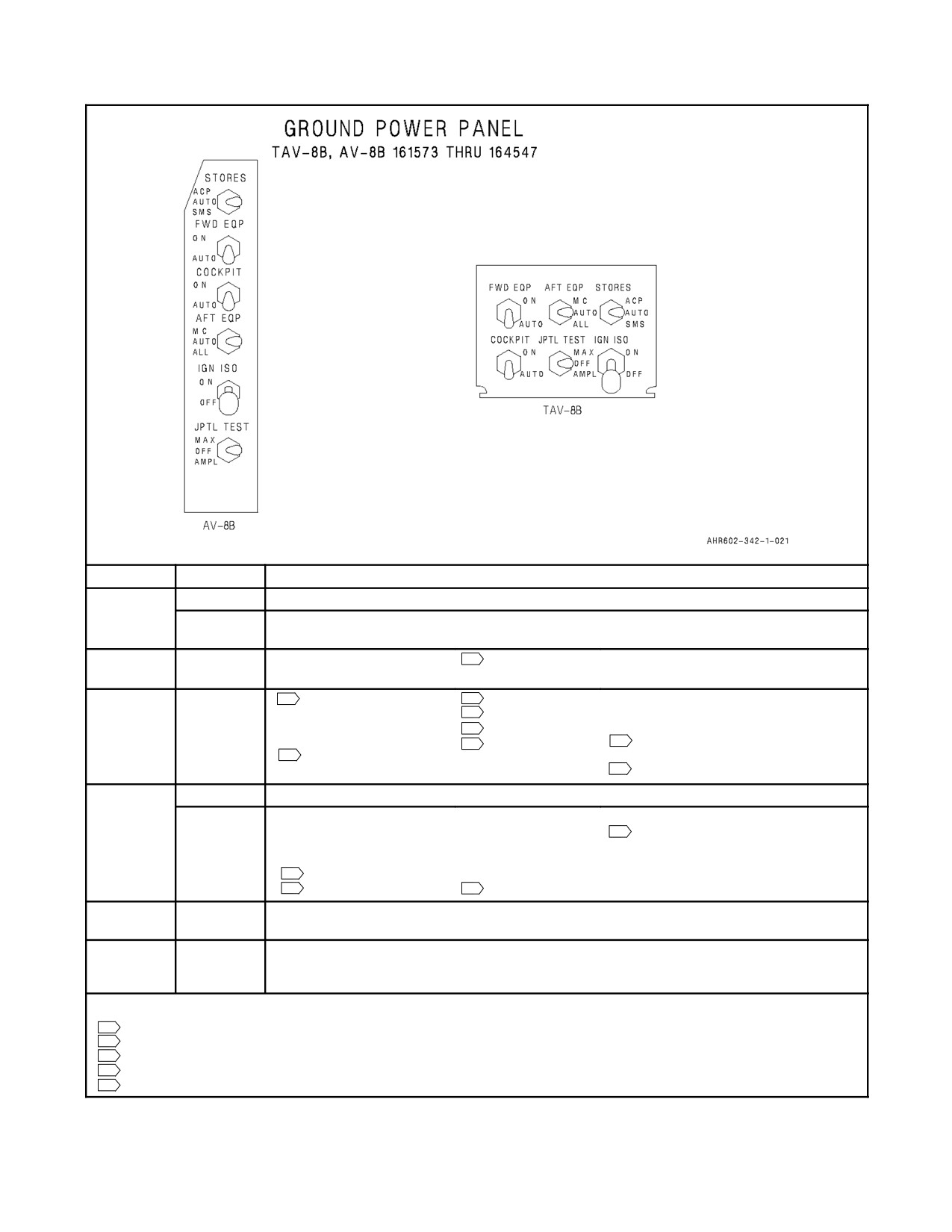
A1-AV8BB--NFM--000
SWITCH
POSITION
EQUIPMENT
ACP
ARMAMENT CONTROL PANEL
STORES
SMS
STORES MANAGEMENT COMPUTER
ARMAMENT CONTROL PANEL
ON
ARBS
2
FLIR
FWD EQP
INS
ON
1
DDI
2
L/R MPCD
TURN AND SLIP INDICATOR
EDP
2
VRS
STANDBY ATTITUDE INDICATOR
HUD
2
DDS
STANDBY ALTIMETER
COCKPIT
UHF
1
HSI
1
STANDBY REFERENCE
5
DISPLAY COMPUTER
ALTIMETER VIBRATOR
3
MOTION PICTURE CAMERA/VRS
MC
MISSION COMPUTER
ALL
MISSION COMPUTER
UHF/VHF NO.1
TACAN
CNI DATA COMPUTER
UHF/VHF NO.2
2
DVMS
AFT EQP
RADAR ALTIMETER
ECM
INVERTER
RADAR BEACON
RWR
4
DISPLAY COMPUTER
IFF
2
TACTS
2
DECM/ASPJ
ON
REFER TO ENGINE FUEL SYSTEM, PARAGRAPH 2.3.6.2
IGN ISO
OFF
MAX
REFER TO ENGINE CONTROLS, PARAGRAPH 2.4.6
JPTL TEST
OFF
AMPL
NOTES:
1
TAV--8B, AV--8B DAY ATTACK
2
AV--8B NIGHT ATTACK
3
AV--8B DAY ATTACK
4
TAV--8B
5
AV--8B 161573 THROUGH 164547
Figure 2-11. Ground Power Switches and Equipment Controlled (Sheet 1 of 2)
2-35
ORIGINAL
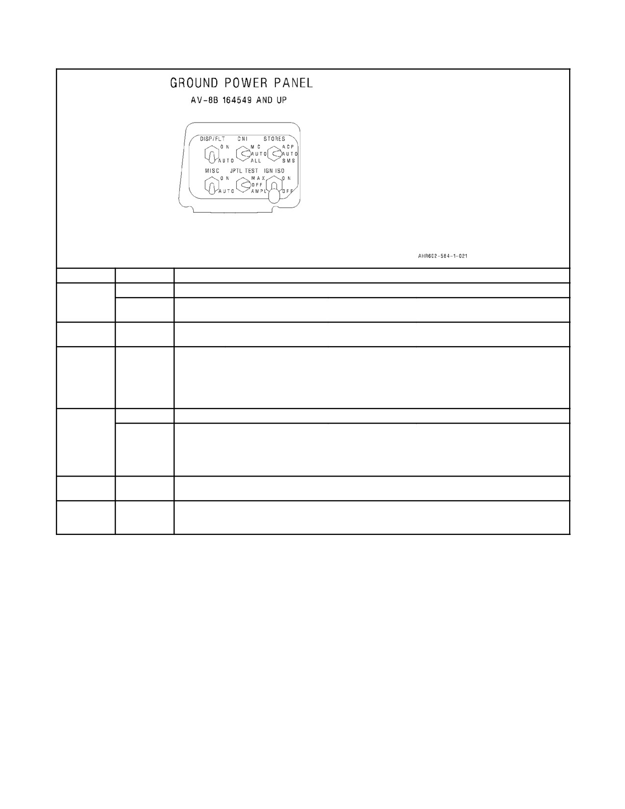
A1-AV8BB--NFM--000
SWITCH
POSITION
EQUIPMENT
ACP
ARMAMENT CONTROL PANEL
STORES
SMS
STORES MANAGEMENT COMPUTER
TACTS
ARMAMENT CONTROL PANEL
DECM/ASPJ
ON
TACAN
RWR
MISC
EXT LTS
ON
HUD
L/R MPCD
TURN AND SLIP INDICATOR
EDP
VRS
STANDBY ATTITUDE INDICATOR
FLIR
DSS
STANDBY ALTIMETER
DISP/FLT
INVERTER
DVMS
STANDBY REFERENCE
UFC
ADC
ALTIMETER VIBRATOR
VRS
SAAHS
DISPLAY PROCESSOR--GENERATOR
MC
MISSION COMPUTER
ALL
MISSION COMPUTER
UHF/VHF NO.1
INS
CNI DATA COMPUTER
UHF/VHF NO.2
DVMS
CNI
RADAR ALTIMETER
ECM
RADAR
RADAR BEACON
RWR
DECM/ASPJ
KY--58
IFF
ON
REFER TO ENGINE FUEL SYSTEM, PARAGRAPH 2.3.6.2
IGN ISO
OFF
MAX
REFER TO ENGINE CONTROLS, PARAGRAPH 2.4.6
JPTL TEST
OFF
AMPL
Figure 2-11. Ground Power Switches and Equipment Controlled (Sheet 2)
2.11.1.3 Formation Lights
Twelve formation lights are provided. One light on each side of the vertical tail fin, one light on each side of the
fuselage just forward of the tail section, one on each upper wing tip aft of the position lights, two on the upper fuselage
just aft of the canopy, and two on each side of the fuselage just below the canopy. The formation lights are controlled
by the FORM lights knob on the exterior lights panel which provides variable lighting between positions OFF and
BRT.
On Radar and Night Attack aircraft, the formation lights operate in the visible mode when the exterior lights master
switch is set to NORM and in the covert (NVG) mode when the exterior lights master switch is set to NVG.
2.11.1.4 Anti--Collision Lights
Two anticollision lights are provided. One light is on the upper fuselage near the midpoint between the tail and
canopy. The other light is on the lower fuselage just forward of the tail section. The anti--collision lights are controlled
by the ANTI COLL lights switch on the exterior lights panel with positions OFF and ON.
ORIGINAL
2-36
A1-AV8BB--NFM--000
On Radar and Night Attack aircraft, the anticollision lights operate in the visible mode when the exterior lights master
switch is set to NORM and in the covert (NVG) mode when the switch is set to NVG.
2.11.1.5 Sideslip Vane Lights
Sideslip vane lights, consisting of a vertical light strip on the back of the vane and a horizontal light strip on top of
thevaneareprovidedtoilluminatethevaneinpoorvisibilityconditionswiththegeardown.Toilluminatethesideslip
vane lights, the instrument lights must be turned on, the gear handle down and the exterior lights master switch in
the EXT LT position on TAV--8B and Day Attack aircraft. On Radar and Night Attack aircraft, the exterior lights
master switch must be in the NORM or NVG position.
On the TAV--8B, an additional sideslip vane light is installed on top of the front canopy bow.
2.11.1.6 Landing/Taxi Lights
There are two landing lights, both on the nose gear strut. The approach landing light has two filaments, one of 250
watts for full brilliance during landing and the other 150 watts for hovering. The approach light is controlled by the
main landing light switch on the trim panel. The main landing gear (MLG) must be down and locked, and the exterior
lights master switch must be on for the approach light switch to operate.
APPROACH (APRCH) - The 250 watt filament illuminates.
HOVER (HVR) - The 150 watt filament illuminates.
OFF - Lights are off.
The other landing light is the auxiliary landing light which contains a 70 watt lamp. The auxiliary landing light is
used as a taxi light. The light is controlled by the auxiliary landing light switch on the exterior lights panel and does
not require the exterior lights master switch to be on.
AUX - Auxiliary landing light illuminates.
OFF - Auxiliary landing light off.
2.11.1.7 Landing/Taxi Lights (Rear Cockpit)
A main landing light switch, similar to the front cockpit switch, is provided on the miscellaneous panel on the left
console in the rear cockpit. The switch has positions APRCH, HVR, and FWD. The APRCH and HVR positions
operate the same as for the corresponding switch positions in the front cockpit. With the rear switch in APRCH or
HVR, the front switch is inoperative. The FWD position gives control of the landing lights to the switch in the front
cockpit.
2.12
INTERIOR LIGHTING
Except for the utility flood, chart light, and kneeboard light, controls for the interior lights are on the interior lights
control panel. On Radar and Night Attack aircraft, all lights are NVG compatible except for the chart and kneeboard
lights and the utility floodlights when white is selected.
2.12.1 Front Cockpit
For console lights, console floodlights, emergency floodlights, and instrument lights in the front cockpit to operate,
the front cockpit lights cutoff switch in the rear cockpit must be in the ON position. With the switch OFF, only the
utility floodlight, chart and knee board lights, and the warning/caution/advisory lights in the front cockpit will
operate. The TEST position of the lights test switch tests the warning/caution/advisory lights in both cockpits.
2.12.2 Rear Cockpit
The rear cockpit contains the same lighting as thefront cockpit. An interiorlights control panel, on the right console,
is identical to the front cockpit panel. Operation of the rear cockpit lighting is identical to the front cockpit lighting,
except as noted in the following paragraphs.
2.12.3 Instrument Lighting
Integral and light panel lighting for the main instrument panel is controlled by the INST PNL knob which provides
variable lighting between positions OFF and BRT.
2-37
ORIGINAL
A1-AV8BB--NFM--000
2.12.4 Console Lighting
Integral and light panel lighting for the left and right consoles, landing gear control and emergency jettison button
panels, hydraulics indicator panel and the cockpit altimeter is controlled by the CONSL knob which provides variable
lighting between positions OFF and BRT.
2.12.5 Floodlights
Three console floodlights are above each console and one (two on Radar and Night Attack aircraft, instrument
floodlight is on each side of the windshield arch. There is also an additional instrument floodlight on each side of
the fixed canopy in the rear cockpit of the TAV--8B. The instrument floodlights are also used for the emergency
floodlights. The console floodlights and instruments floodlights are white lights (on the Radar and Night Attack
aircraft they are night vision goggle (NVG) green, The lights are controlled by the FLD knob which provides variable
lighting between positions OFF and BRT.
2.12.5.1 Emergency Floodlights
The instrument floodlights provideemergency lighting in thecockpit. Theselights comeon automatically whenever
power to the 115 volt ac bus, which provides power for normal instrument lighting, is lost. With loss of the essential
115 volt bus and the INST PNL knob out of the OFF position emergency 28 volts is provided for operation of all
console and emergency floodlights. The lights are controlled by the FLD knob in both normal and emergency
operation. The knob provides variable lighting between positions OFF and BRT.
2.12.5.2 Utility Floodlight (TAV--8B, AV--8B Day Attack Aircraft)
A portable utility floodlight is provided and normally stowed above the right console. An alligator clip attached to
the light may be used to fasten the light at various locations in the cockpit at the pilot’s discretion. The light contains
a knob which provides variable lighting between off and bright, and a button which when pressed causes the light
to come on at full intensity. The light also contains a rotary selector for red or white lighting. The light is on the alert
bus.
2.12.5.3 Utility Floodlights (AV--8B Radar and Night Attack Aircraft)
Two portable utility floodlights are provided and normally stowed above the right and left console. An alligator clip
attached to each light may be used to fasten the light at various locations in the cockpit at the pilot’s discretion. The
lights contain a knob which provides variable lighting between off and bright, and a button which when pressed
causes the lights to come on at full intensity. The lights also contain a rotary selector for green or white lighting. The
lights are powered by the alert bus.
2.12.6 Warning/Caution Lights Knob
A knob labeled WARN/CAUT is provided on the interior lights control panel to switch the warning/caution/advisory
lights from bright intensity to the low intensity range, and then vary the brightness within the low intensity range.
Warning/caution/advisory lights can be switched to the low intensity range by placing the warning/caution lights
knob momentarily to RESET, providing the instrument panel knob is out of the OFF position and the flood knob is
less than half way to BRT. Once in the low intensity range, the warning/caution/advisory lights can be brought back
to high intensity by turning the flood knob to BRT, turning the instrument panel knob to the OFF position, or
removing and re--applying power to the aircraft.
2.12.7 Compass/Lights Test Switch
The COMP/LTS TEST switch is provided to control the standby compass light and test the warning/caution/advisory
lights.
COMP - The compass light is on, provided CONSL knob is out of OFF position.
OFF - Compass light and test function are off.
TEST - Serviceable warning/caution/advisory lights come on. TEST position is spring--loaded to off.
2.12.7.1 Compass/Lights Test Switch (Rear Cockpit)
The COMP position is a dummy position, since the rear cockpit does not have a standby compass.
ORIGINAL
2-38
A1-AV8BB--NFM--000
2.12.7.2 Front Cockpit Lights Switch (Rear Cockpit)
The front cockpit lights switch on the rear cockpit left console outboard of the miscellaneous panel is used to control
operation oftheconsolelights, consolefloodlights,emergency floodlights,and instrumentlights inthefrontcockpit.
OFF - Controlled lighting inoperative.
ON - Full operation of controlled lighting by controls in the front cockpit.
2.12.8 Chart and Kneeboard Lights
A chart light is installed on the left windshield arch above the emergency floodlight and a knee board light is installed
above the emergency floodlight on the right windshield arch. These lights swing out from their stowed positions and
are turned on when positioned 17° or more from the stowed position. Once turned on, rotating the bezels varies
lighting brightness. Returning them to within 17° of the stowed positions turns off the lights. The knee board light
is on the alert bus and the chart light is on the emergency bus.
2.13
HYDRAULIC POWER SUPPLY SYSTEM
Hydraulic power is generated by two engine driven hydraulic pumps and is distributed by two independent 3,000
psi hydraulic systems; Hyd 1 and Hyd 2. Both systems provide power to the stabilator, aileron, and flap dual system
flight control actuators. Either system is capable of providing the power necessary for actuator operation in the event
of the loss of theother system. Hyd 1 provides powerfor thevarious utility functions, in addition to the flight control
actuation systems. A flow control priority valve in Hyd 1 restricts the flow to the landing gear when the system
pressure drops below 2,000 psi in order to maintain pressure for the flight control actuation system. Hyd 2 is dedicated
to the flight control actuators except upon loss of Hyd 1, it is then used for emergency nosewheel steering when the
aircraft is on the ground. The rudder automatically reverts to manual operation in the event of Hyd 1 pressure loss.
Emergency wheel braking can be accomplished by stored accumulator power and emergency landing gear extension
can be accomplished by stored pneumatic power if normal landing gear extension fails. Transient demands can exceed
pump capacity. If this occurs, the extra demand is supplied by an accumulator in each system. Each system contains
relief valves to prevent overpressurization. Pressure switches and electronic pressure transmitters are installed in each
hydraulic system to sense pressure and transmit signals to the cockpit indicators. See Hydraulic System foldout for
simplified schematic of the hydraulic power system.
Steady state Hyd 1 and Hyd 2 indicator readings of 3000 ±200 psi are normal throughout engine rpm range with no
hydraulic system demands.
2.13.1 HYD 1 Power Generation System
The Hyd 1 loads can be divided into three groups:
1. PUMP OUTPUT AND ACCUMULATOR - Ailerons, stabilator, flaps, rudder, aileron droop, and auto
stabilization servos.
2. PUMP OUTPUT - Fuel flow proportioner, nosewheel steering, wheel brake, Q--feel, LIDS, speedbrake, and
in--flight refueling probe.
3. NON--PRIORITY - Landing gear functions.
The first group is supplied from the system accumulator section, downstream of the accumulator check valve. In the
event of large simultaneous flow demands, in excess of the pump capacity, the accumulator provides additional power
to this group of loads. The first group is isolated from the second group by the check valve to maximize the time
available before discharge of the system accumulator following an engine shutdown. This allows more time for flight
controls operation and improves aircraft control during an engine restart or pilot egress. The second group is supplied
from the main system just downstream of the pressure filter. The loads have either relatively low flow demands, or
the flow demands occur only on the ground. The landing gear is supplied from the main system via a priority valve.
The priority valve starts restricting the landing gear flow when the system pressure drops below 2,000 psi. Landing
gear flow is zero if system pressure drops below 1,600 psi. Emergency nitrogen/helium is available as a backup to
operate the non--priority landing gear functions.
2-39
ORIGINAL
A1-AV8BB--NFM--000
2.13.2 HYD 2 Power Generation System
The Hyd 2 loads are the aileron actuators, stabilator actuator, and flap actuators.
Hyd 2 also provides a back--up supply for the nosewheel steering, via a solenoid operated switching valve
incorporated into the nose gear steering selector/switching valve. The use of Hyd 2 as a back--up for nosewheel
steering is inhibited except with weight--on--wheels, with Hyd 1 pressure less than 1,400 psi, and with nosewheel
steering selected. The back--up supply is flow limited to retard Hyd 2 depletion if a nosewheel steering line failure
is the cause of the Hyd 1 failure. In addition to the Hyd 2 backup system, a Hyd 2 accumulator is included for
temporary backup of nosewheel steering. The Hyd 2 accumulator will provide about 3 cycles (a cycle is from neutral
to 3° L to 3° R and back to neutral) of nosewheel steering if both hydraulic pump outputs are lost. Steering reaction
will be slower when operating on HYD 2.
2.14
FLIGHT CONTROL SYSTEM
2.14.1 Primary Flight Controls
The primary flight controls (see Figure 2-12) are the stabilator, rudder and ailerons for aerodynamic control and a
reaction control system for jetborne control. The stabilator, rudder, and ailerons are hydraulically powered. Artificial
feel systems simulate aerodynamic feel. The trim system moves the entire control surface through the actuator.
Secondary controls are the flaps, drooped ailerons and speedbrake.
If the front and rear cockpit trim simultaneously in opposite directions, the resulting trim will be nose down, left wing
down, and left rudder.
2.14.1.1 Aileron Control System
The lateral control system consists ofthe control stick, high speed aileron stop, spring feel unit, trim actuator, cables,
control rods, two tandem hydraulic actuators, two ailerons and two roll reaction control valves. With the landing gear
down,ailerontravelduetostickmovementis about25°upand 10°down. Withthelandinggearup(except onAV--8B
162070 or 162071), or above 0.4 Mach, aileron travel is reduced because of the solenoid operated high speed stop
at the base of the control stick; however, the stop can be overridden to obtain full aileron travel. On AV--8B 162942
and up, aileron deflection is increased between 0.88 and 0.96 Mach when angle of attack is between --2.6° and 9.1°
to improveroll rate. At 0.92 Mach theroll rateis increasedapproximately 40°persecondproviding a120°persecond
roll rate capability. Lateral stick movement is transmitted by control rods and cables to the aileron actuator control
valves. The control valves meter hydraulic fluid to tandem power cylinders in proportion to the displacement. The
tandem power cylinders allow simultaneous use of both hydraulic systems. If a single hydraulic system fails, the
remaining system will supply adequate power for control.
2.14.1.1.1 Lateral Control Feel and Stop
Aileron feel is provided by a nonlinear spring unit. With the landing gear up, or above 0.4 Mach, solenoid operated
aileron stops at the base of the control stick restrict lateral stick movement to about 75 percent of full throw. The stops
are actuated by a switch in the air data computer. The stops are spring loaded and can be overridden.
2.14.1.1.2 Lateral Trim System
The lateral trim system consists of a trim switch on the stick grip (Figure 2-13) and an electric trim actuator. When
the switch is actuated, the trim actuator repositions the spring feel unit which, in turn, moves the ailerons. An auto
trim system automatically trims the aircraft when automatic flight control (AFC) is engaged. Manual trim overrides
auto trim. Total trim travel is 5.6° trailing edge up/4.5° trailing edge down.
2.14.1.1.3 Aileron Trim Indicator
The aileron trim indicator, on the left console, indicates trim setting. The left end of the arc represents full left trim
and the right end represents full right trim.
ORIGINAL
2-40
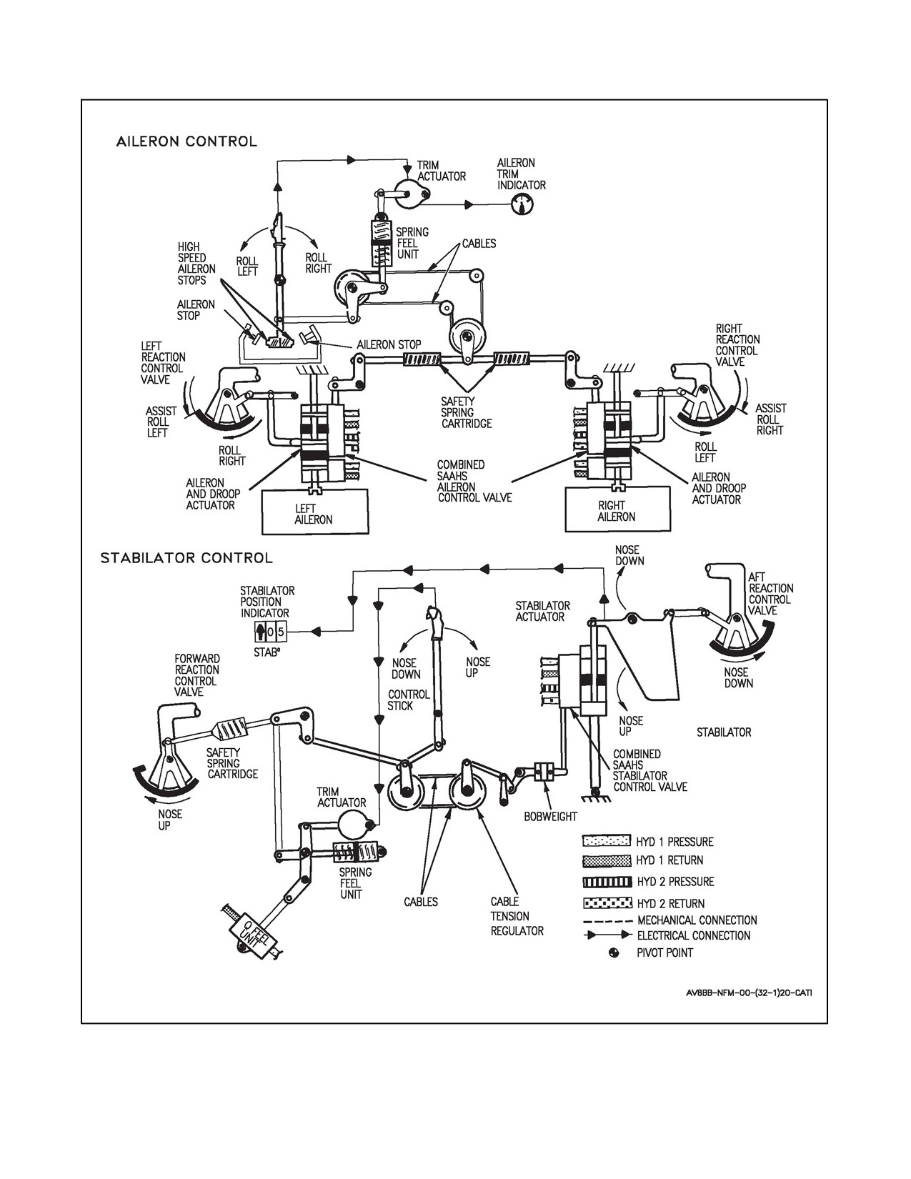
A1-AV8BB--NFM--000
Figure 2-12. Flight Controls (Sheet 1 of 2)
2-41
ORIGINAL
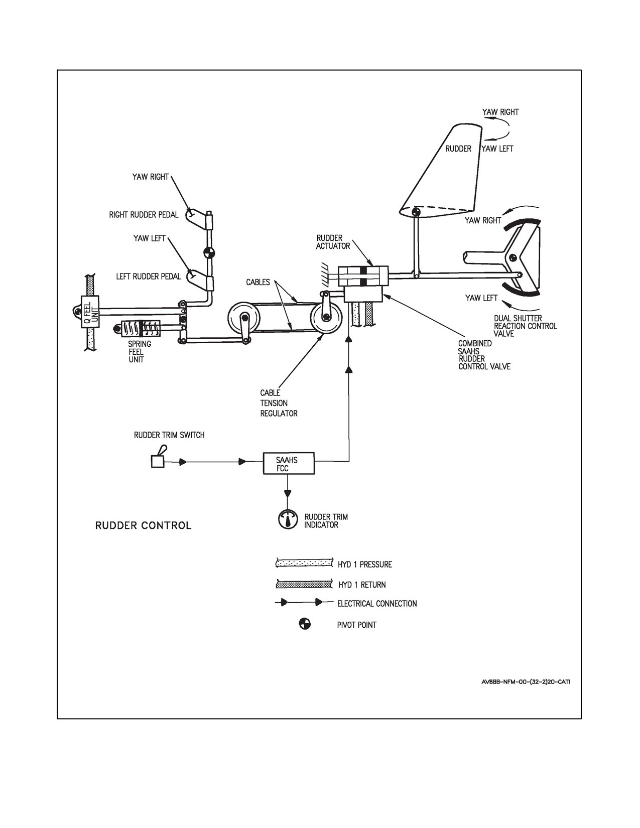
A1-AV8BB--NFM--000
Figure 2-12. Flight Controls (Sheet 2)
ORIGINAL
2-42
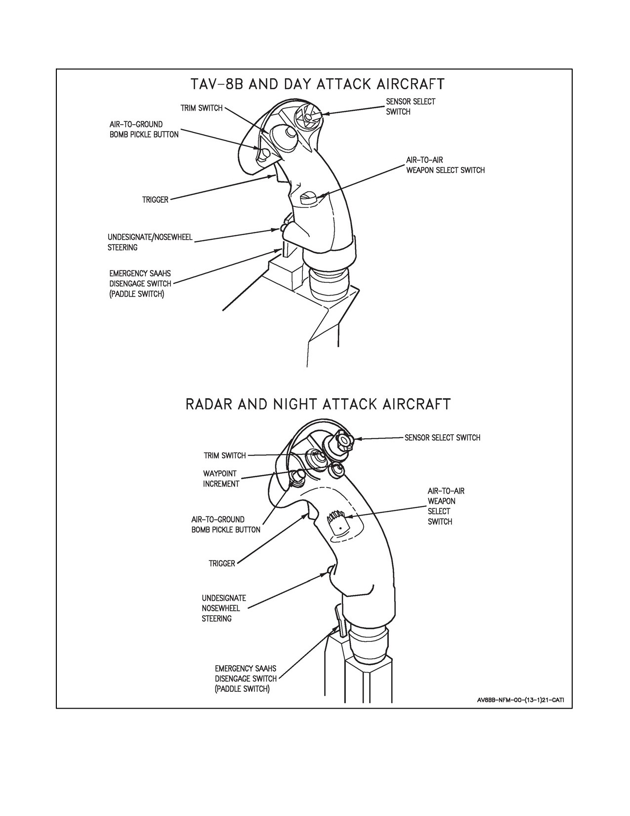
A1-AV8BB--NFM--000
Figure 2-13. Control Stick Grip
2-43
ORIGINAL
A1-AV8BB--NFM--000
2.14.1.1.4 Aileron Safety Cartridge Assemblies
An aileron safety cartridge assembly, located at the intersection of the fuselage and wing on each side of the aircraft,
permits control of the aircraft by allowing operation of one aileron if the other is jammed. These assemblies normally
act as a solid link. In the event of one wing’s aileron becoming jammed, stick pressure will override that wing’s
cartridge assembly’s spring tension, thereby allowing movement of the opposite wing’s aileron. Stick pressure
required will vary depending on the deflection angle of the jammed aileron. An increase in lateral stick pressures may
be an indication of compression or extension of the aileron safety spring cartridge assembly. Reducing the air loads
acting upon the aircraft will decrease the aircraft’s roll rate tendency for a given jammed deflection.
2.14.1.2 Stabilator Control System
The longitudinal control system consists of the control stick, spring feel unit, hydraulically operated Q--feel unit,
cables, control rods, a tandem hydraulic actuator, a stabilator, and two pitch reaction control valves. Stabilator travel
is about 10°trailing edgeup and11°trailingedgedown.Longitudinal movementofthestick istransmitted bycontrol
rods and cables to the stabilator actuator control valve. The control valve meters hydraulic fluid to the tandem power
cylinders in proportion to the displacement. The tandem power cylinders allow simultaneous use of both hydraulic
systems. If a single hydraulic system fails, the remaining system will supply adequate power for control.
2.14.1.2.1 Longitudinal Control Feel
Longitudinal control feel is provided by ahydraulicQ--feelunit poweredby theHYD 1system andanonlinearspring
unit. The spring unit provides stick forces independent ofairspeed up to 165 knots. Above165 knots, the Q--feel unit
increases stick forces as airspeed increases. Hydraulic supply for the Q--feel is controlled by a valve which is
energized open by the air data computer at 165 knots. The Q--feel system may be shut off by placing the Q--feel switch,
on the left console, OFF. With the Q--feel off, airspeed over 500 knots may cause a pilot induced oscillation (PIO).
A bobweight is installed on the rear bellcrank (Figure 2-12) which controls the stabilator actuator control valve. The
addition of the bobweight to the longitudinal flight control system improves the pilot’s stick feel forces and the
aircraft’s pitch flying qualities.
2.14.1.2.2 Longitudinal Trim System
The longitudinal trim system consists of a trim switch on the stick grip and an electric trim actuator. When the trim
switch is actuated, the actuator repositions the spring feel unit which, in turn, moves the stick neutral position. Total
trim travel is 7.5° stabilator trailing edge down (nose down) and 4° stabilator trailing edge up (nose up). An auto trim
system automatically trims the aircraft when AFC is engaged. Manual trim overrides auto trim.
2.14.1.2.3 Stabilator Position Indicator
Stabilator position is provided on both the EDP and the DDI. The EDP is located on the right side of the main
instrument panel and the DDI on the left side (Day Attack aircraft) or either side of the main instrument panel for
Radar and Night Attack aircraft. Both indicators display stabilator position in degrees with an arrow to indicate nose
up or nose down. Stabilator position on the DDI is displayed on the engine data display and is accessible through
the menu display by selecting ENG.
2.14.1.2.4 Forward RCV Safety Cartridge Assembly
A safety spring cartridge is located in the longitudinal axis between the forward reaction control valve (RCV) and
the RCV servo. The double acting spring cartridge is designed to allow the RCV servo to function and to provide
aft longitudinal control (stab) if the forward RCV jams, longitudinal stick force will override the cartridge assembly’s
spring tension, allowing the control linkages between the stick and stabilator actuator to move. Pitch authority will
be reduced during jetborne or semi--jetborne flight. The reduced authority should be compensated for by increasing
the airspeed, thereby increasing the pitch control authority of the stab. With nozzles aft (butterfly valve closed or no
RCS pressure), the forward RCV jam will have no effect on controllability of the aircraft.
ORIGINAL
2-44
A1-AV8BB--NFM--000
2.14.2 Control Stick
The control stick is mounted to permit left, right, fore, and aft movement for control of the ailerons and stabilator
(see Figure 2-13). The stick grip contains seven controls (eight on Radar and Night Attack aircraft): a sensor select
switch, a four way trim switch, an air--to--ground bomb pickle button, a trigger, an air--to--air weapon select switch,
a nosewheel steering switch and an emergency SAAHS disengage switch (paddle switch). A waypoint increment
switch (WINC) is added to the control stick on Radar and Night Attack aircraft.
2.14.3 Rudder Control System
The rudder control system consists of the rudder pedals, aspring feel unit, cables, control rods, rudder pedal shakers,
rudder actuator, rudder and a dual reaction control valve. Rudder travel is 15° right and left. Movement of the rudder
pedals is transmitted by control rods and cables to the rudder actuator control valve. The rudder actuator is powered
by the HYD 1 system. Direct mechanical control of the rudder is provided if a hydraulic failure occurs.
2.14.3.1 Rudder Feel System
RudderfeelisprovidedbytheQ--feelunit andalinearspring unit.Thespringunit providesrudderforcesindependent
of airspeed up to 165 knots. Above 165 knots, the Q--feel unit increases rudder forces as airspeed increases. The
Q--feel system may be shut off by placing the Q--feel switch on the left console OFF.
2.14.3.2 Rudder Trim System
Theruddertrim system consists ofatrim switch on the left console which positions therudder actuatorand has about
2° authority.
2.14.3.3 Rudder Trim Indicator
The rudder trim indicator is on the left console. The left end of the arc represents full left trim and the right end
represents full right trim. Rudder trim indication is furnished from the stability augmentation and attitude hold system
(SAAHS) computer.
2.14.3.4 Rudder Pedal Shakers
At low speed, rudder pedal shakers give early warning of sideslip. In flight, at approximately 165 knots or below,
if over 0.06 lateral g’s occur, one of the two shakers will oscillate its associated pedal, giving a cue to the pedal that
should be pushed.
The rudder pedal shaker is only enabled for the preceding conditions if the aircraft configuration is one of the
following:
1. Gear down with STOL flaps selected.
2. Gear down and flaps AUTO/CRUISE at less than 0.3 Mach.
3. Gear up and flaps STOL at less than 0.3 Mach.
4. Nozzles greater than 10°.
Each shaker is an electric motor which drives an eccentric to shake its pedal. The shaker is activated through the
SAAHS computer logic using inertial navigation system (INS) lateral acceleration inputs. The INS also provides
lateral acceleration to the display processor to provide sideforce indication on the head--up display (HUD). The rudder
pedal shaker (RPS) switch, on the left console allows the RPS system to be tested on the ground.
2.14.3.5 Rudder Pedals Adjustment
When the rudder pedals adjust knob is pulled, the rudder pedals can be pushed forward or allowed to move aft under
spring pressure. Thepedalsshould berestrained fromsnapping aftwhen therudderpedaladjust knobis pulled.When
the knob is returned, the pedals will lock in the selected position. Ensure the knob is returned fully without use of
force, retaining no feeling of springiness. Press hard on both pedals to ensure they are locked.
2-45
ORIGINAL
A1-AV8BB--NFM--000
2.14.3.6 Rudder Pedal Shaker Switch
The Rudder Pedal Shaker (RPS) switch is on the forward end of the left console and has three positions.
OFF - Rudder pedal shakers disables.
ON - Rudder pedal shakers enabled.
TEST - Allows therudder pedal shakers to be tested on theground. Whiletaxiing with the nosewheel steering
engaged, hold the RPS switch to TEST and turn the aircraft with nosewheel steering. This imposes a side force
from the side with the forward deflected rudder pedal. Check that the rear rudder pedal oscillates briefly and
the HUD sideforce symbol briefly indicates sideforce in the direction of applied rudder.
The RPS switch is not installed in the rear cockpit of the TAV--8B.
2.14.4 Reaction Controls
Control is maintained, when jetborne, by reaction control valves. These are shutter valves supplied with bleed air
ducted from the HP compressor, through a master butterfly valve which is interconnected with the engine nozzles
control mechanism. The master butterfly valve opens automatically when the nozzles are deflected from fully aft.
Air supply is progressive as the nozzles are lowered from 0° to 36° down.
2.14.4.1 Duct Pressure Indicator
Theduct pressureindicatorindicatesreaction controlduct pressure.When thenozzles arefull aft,themasterbutterfly
valve is closed and the indicator indicates 0 to 3 psi. As the nozzles are rotated and the master butterfly valve opens,
the duct pressure indicator will indicate duct pressure.
2.14.4.2 Lateral Control
Lateral control is provided by two wing tip reaction control valves which are interconnected with the aileron
actuators. These blow downward when the associated aileron is trailing edge down. The downblowing valve becomes
fully open at about half aileron travel and then the opposite wing reaction valve opens progressively and blows
upwards.
2.14.4.3 Longitudinal Control
Longitudinal control is provided by two downblowing reaction control valves, one at the nose and one at the tail.
The forward valve is linked to the control column through a safety spring cartridge. An actuator on the forward valve
linkage is used for the stability augmentation system (SAS). The aft valve is linked directly to the stabilator. Neutral
control coincides with 2° nose down trim, at which time both valves are just closed.
2.14.4.4 Directional Control
Directional control is provided by a double reaction control valve at the tail. This is connected to the rudder actuator
and blows in accordance with rudder movement.
2.15
SECONDARY FLIGHT CONTROLS
2.15.1 Flaps
The electro--hydraulic operated trailing edge flaps (see Flap System foldout) are controlled by a dual channel
electronic flap controller, a dual system hydraulic control valve and two dual tandem actuators. Flap positioning is
provided by the flap controller in accordance with switch selection by the pilot. A STOL mode (25° to 62°), an AUTO
mode (0° to 25°), and a CRUISE mode (5°) may be selected. Two cockpit switches, an air data computer, a landing
gear down relay, a WOW relay, dual sensors on the engine nozzles, and dual sensors on the flaps, provide control
inputs to the flap controller. Dual output commands to the hydraulic module control two hydraulic sources to two
dual tandem hydraulic cylinders. Engine nozzle and flap positions are shown on the HUD. Flap position is also
displayed on the flap position indicator. Nozzle position is also displayed on the engineperformance indicator(EPI).
The flap controller uses two electric inputs to provide two separate channels for flap control.
ORIGINAL
2-46
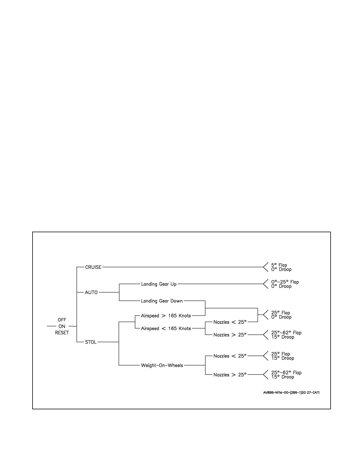
A1-AV8BB--NFM--000
2.15.1.1 For Aircraft Without ECP--255 R1
Channel 1 is powered by the switched battery bus. Channel 2 is powered by the emergency 28 volt dc bus. The flap
controller shuts down a failed channel depending on the detected fault source. Power interruption to the emergency
28 volt dc bus may cause loss of channel 2. This can occur when a generator or the main TRU comes on or goes off
line, such as during engine start or when the DC test switch is used. Channel 1 will not be lost due to a power
interruption if the battery switch is in BATT. Single failures do not affect flap system performance. If a dual channel
controller failure or an asymmetric flap greater than 3° occurs, the dual shutoff valves will lock the flaps in place.
With a dual channel controller failure, the flaps can then be retracted with the emergency retract button on the throttle.
Figure 2-14 describes the flap and aileron droop logic.
2.15.1.2 For Aircraft With ECP--255 R1
The channel 1 primary flap power comes from the switched battery bus. The channel 2 primary flap power comes
from the emergency 28 volt dc bus. The primary flap power is removed from the flap controller when the flap switch
is in the OFF position. The digital flap controller is provided an additional source of switched battery bus power that
is not routed through the flap ON/OFF switch. This additional power source allows the flap and nozzle displays to
remain active when the flap switch is in the OFF position. This additional power source also reduces the likelihood
of a nuisance flap system fault when a generator or main TRU comes on or goes off line, such as during engine start
or when the DC TEST switch is used. Single failures do not affect flap system performance. If two similar controller
failures occur or flap asymmetry exceeds 5°, the dual shutoff valves will lock the flaps in place. When the flaps are
locked, the flaps can be retracted with the emergency retract button on thethrottle. Figure2-14 describes the flap and
aileron droop logic.
Figure 2-14. Flap and Aileron Droop Logic
2-47
ORIGINAL

A1-AV8BB--NFM--000
2.15.2 Flap Select Switches and Indicators
2.15.2.1 Flaps Power Switch (AV--8B)
The flaps power switch is on the landing gear control panel.
OFF
For aircraft without ECP--255 R1: Shuts off power to the flaps mode switch and
flap controller. Selecting flaps OFF causes a FLAPS warning and loss of flap and
nozzle position indication.
OFF
For aircraft with ECP--255 R1: Shuts off power to the flaps mode switch.
Selecting flaps OFF causes a FLAPS warning and removes primary flap power
from the flap controller. Flap and nozzle position indications are still active.
ON
For aircraft without ECP--255 R1: Applies power to the flaps mode switch and
flap controller.
ON
For aircraft with ECP--255 R1: Applies power to the flaps mode switch and
provides primary flap power to the flap controller.
RESET
Momentary. Resets flap controller failure logic and stops an initiated BIT.
2.15.2.2 Flaps Power Switch (TAV--8B)
The flaps power switch is on the landing gear control panel.
OFF
For aircraft without ECP--255 R1: Shuts off power to the flaps mode switch and
flap controller. Selecting flaps OFF causes a FLAPS warning and loss of flap and
nozzle position indication.
OFF
For aircraft with ECP--255 R1: Shuts off power to the flaps mode switch and
removes primary flap power from the flap controller. Selecting flaps OFF causes
a FLAPS warning. Flap and nozzle position indications are still active.
FWD
Flaps power controlled by front cockpit switch.
RESET
Momentary. Resets flap controller logic and stops an initiated BIT.
2.15.2.3 Flaps Mode Select Switch
The flaps mode select switch is located on the landing gear control panel. See Figure 2-15 for flap schedules.
STOL
Provides 25° flaps if airspeed over 165 knots. Below 165 knots, flaps are
scheduled from 25° to 62° as nozzles are rotated from 25° to 50°. Below 165
knots, with nozzles over 25°, provides 15° aileron droop. With
weight--on--wheels, ailerons droop 15°.
AUTO
With the landing gear up, flaps are scheduled from 0° to 25° as a function of
Mach number, airspeed, and angle--of--attack. With the landing gear down,
provides 25° flaps even if an AUT FLP caution is present.
CRUISE
Provides 5° flaps.
On TAV--8B aircraft this switch is located in the front cockpit only. However, the flaps mode selected in the front
cockpit is shown in the rear cockpit on an indicator on the landing gear control panel.
ORIGINAL
2-48
A1-AV8BB--NFM--000
2.15.2.4 Flaps Schedule
Figure2-15 covers both STOL and AUTO flap schedules. To usethechart to determineSTOL flap anglewith respect
to NOZZLE ANGLE for airspeeds less than 165 KCAS use bottom chart and enter the NOZZLE ANGLE on the
horizontal axis. From NOZZLE ANGLE entry angle rise vertically until you intersect the printed heavy black line.
From this intersection move horizontally to vertical axis and record corresponding FLAP ANGLE.
To determine FLAP ANGLE in AUTO using the upper chart in Figure 2-15. This chart is actually three charts in a
single display. Moving from left to right.
2.15.2.4.1 Using INDICATED AOA
The FLAP ANGLE as a function of INDICATED AOA is determined for both T/AV--8B using the heavy black solid
line. Enter INDICATED AOA on the horizontal axis and rise vertically until the printed heavy black line is
intersected. From this intersection move horizontally to the vertical axis and record corresponding FLAP ANGLE.
The resulting FLAP ANGLE determined by INDICATED AOA chart may or may not yield the correct answer. The
FLAP ANGLE must be determined as a result of MACH NUMBER and AIRSPEED. Use the lowest FLAP ANGLE
result as the planned FLAP ANGLE for any particular condition of AOA, MACH No, and AIRSPEED.
2.15.2.4.2 Using MACH NUMBER
ThischartcontainsasolidheavylineforusewithTAV--8BandadashedlineforsingleseatAV--8B.Below0.3MACH
and above 0.87 MACH the heavy line is used for both T/AV--8B. Entering the displayed MACH number on the
horizontal axis and rise vertically until the heavy solid (TAV--8B) or dashed line (AV--8B) is intersected. From this
intersection move horizontally to the vertical axis and record corresponding FLAP ANGLE. The resultant FLAP
ANGLE determined by MACH NUMBER may or may not yield the correct answer. The FLAP ANGLE must be
determined as a result of INDICATED AOA and AIRSPEED. Use the lowest FLAP ANGLE result as the planned
FLAP ANGLE for any particular condition of AOA, MACH No, and AIRSPEED.
2.15.2.4.3 Using INDICATED AIRSPEED
ThischartcontainsasolidheavylineforusewithTAV--8BandadashedlineforsingleseatAV--8B.Below200KCAS
to 50 KCAS the solid line is used for both. Entering the displayed airspeed on the horizontal axis and rise vertically
until the heavy solid (TAV--8B) or dashed line (AV--8B) is intersected. From this intersection move horizontally to
the vertical axis and record corresponding FLAP ANGLE. The resultant FLAP ANGLE determined by AIRSPEED
may or may not yield the correct answer. The FLAP ANGLE must be determined as a result of MACH NUMBER
and INDICATED AOA and use the lowest FLAP ANGLE result as the planned FLAP ANGLE for any particular
condition of AOA, MACH No, and AIRSPEED.
2.15.2.5 Emergency Flap Retract Button
The emergency flap retract button on the throttle (Figure 2-6) retracts the flaps when held pressed when both flap
channels have failed or flap power switch is OFF.
2.15.2.6 Flap Position Indicator
The left flap position indicator is on the landing gear control panel and is controlled by channel 1. If the indicator
fails it will show “BARBER POLE”. Right flap position is shown on the HUD in the V/STOL mode and is controlled
by channel 2.
2.15.2.7 Flaps Warning Light
For all aircraft with or without ECP--255 R1:
The FLAPS warning light, a red light, on the warning/threat light panel (green light on the warning light panel on
AV--8B Radar and Night Attack aircraft), indicates a dual channel flap failure or flap power switch OFF. On TAV--8B
163856 and up, AV--8B 163519 and up, a FLAP FAILURE, FLAP FAILURE voice warning is provided in
conjunction with the FLAPS warning light.
2-49
ORIGINAL
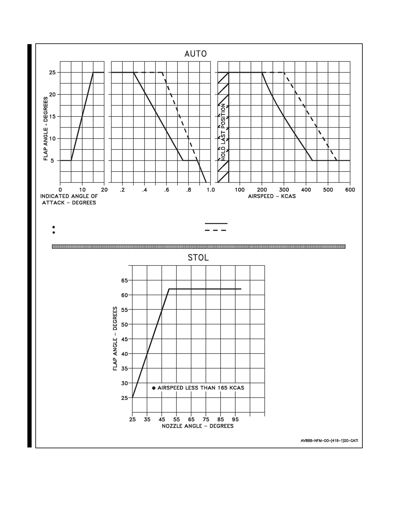
A1-AV8BB--NFM--000
INDICATED MACH NUMBER
(FOR AV--8B AND TAV--8B)
TAV-8B
LANDING GEAR UP.
AV-8B
FLAPS COMMANDED TO THE SMALLEST COMPUTED
ANGLE BETWEEN AOA, IMN, AIRSPEED.
Figure 2-15. Flap Schedules
ORIGINAL
2-50
A1-AV8BB--NFM--000
For aircraft with ECP--255 R1:
If the FLAPS warning light is not cleared, the FLAP FAILURE, FLAP FAILURE voice warning will reoccur once
after 15 seconds if the flaps remain greater than 25°.
2.15.2.8 Flaps Caution Lights
For aircraft without ECP--255 R1:
The three flaps caution lights, (FLAPS 1, FLAPS 2, and AUT FLP) are on the caution/advisory light panel. FLAPS
1 or FLAPS 2 indicates a failure of flap channels 1 or 2. A FLAPS 2 caution may appear if the generator fails due
to a momentary loss of power.
For aircraft with ECP--255 R1:
The three flaps caution lights, (FLAPS 1, FLAPS 2, and AUT FLP) are on the caution/advisory light panel. FLAPS
1 or FLAPS 2 (but not both) indicates a failure in the flap system but no loss of function. The digital flap controller
will keep the flaps engaged as long as a valid signal path exists to control the flaps. A FLAPS 1 or FLAPS 2 caution
means that one more failure could result in locked flaps.
For all aircraft with or without ECP--255 R1:
The AUT FLP caution light indicates the loss of AUTO mode computation or air data computer input. On TAV--8B
163856 and up, and on AV--8B 163519 and up, a CAUTION, CAUTION voice warning is provided in conjunction
with either a FLAPS 1, FLAPS 2, or AUT FLP caution light. The flaps caution lights are yellow on the TAV--8B and
AV--8B Day Attack aircraft and are green on the AV--8B Radar and Night Attack aircraft.
2.15.2.9 STO Advisory Light
The green STO advisory light indicates the flap mode select switch is in STOL.
2.15.3 Flap IBIT
A pilot initiated built--in--test (IBIT) may be performed. To accomplish an IBIT, place the flap power switch from
OFF to ON. RESET will inhibit IBIT. Press the flaps BIT switch on the landing gear control panel. During the IBIT
sequence, FLAPS 1, FLAPS 2, and AUT FLP caution lights and the FLAPS warning light must be on prior to
initiation of the BIT. After a successful IBIT, the FLAPS caution and warning lights will go out and the flaps will
go to the selected mode. Failure of a FLAPS caution light to go out within 25 seconds indicates a NO GO condition.
If this occurs, place the flaps power switch OFF, beep the flaps up, place the flaps power switch ON, and again initiate
IBIT.
For aircraft without ECP--255 R1:
The IBIT system is inoperative with weight off the wheels, landing gear up, airspeed greater than 165 knots or after
RESET selected. If RESET is selected during IBIT, IBIT will immediately stop and the system will return to normal
operation. Once IBIT is successfully completed, it will be inhibited unless the flaps power switch is cycled through
OFF to ON. Post flight flap IBIT should not be performed since it clears the fault isolation indications on the flap
controller.
For aircraft with ECP--255 R1:
The IBIT system is inoperative with weight off the wheels, landing gear up, airspeed greater than 165 knots, nozzles
rotated less than 10°, or after RESET selected. If the AUT FLAP warning light flashes twice immediately after the
flaps BIT switch is pressed, verify that the nozzles are rotated to at least 10°. If the nozzles were rotated less than
10°, rotate them to beyond 10° and place the flaps power switch OFF and then to ON before pressing the flaps BIT
switch. If RESET is selected during IBIT, IBIT will immediately stop and the system will return to normal operation.
OnceIBIT is successfully completed, it will be inhibited unless theflaps powerswitch is cycled through OFF to ON.
2-51
ORIGINAL
A1-AV8BB--NFM--000
2.15.4 Aileron Droop
Aileron droop is accomplished by a single--cylinder aileron droop actuator in tandem with each aileron actuator. The
aileron droop actuators are powered by HYD 1. Aileron droop operation requires no pilot action. Inflight, with the
flap switch in STOL, the ailerons droop 15° when airspeed is below 165 knots and nozzles are over 25°. This
establishes a new aileron neutral position and aileron travel is 10° down to 25° up. After takeoff with the flap switch
in STOL, the ailerons begin to reposition up (0° droop)3 seconds after weight--off--wheels and nozzles less than 25°,
or exceeding 165 knots. Aileron droop requires approximately 7 seconds to reposition 15° down after selection of
STOL flaps with weight--on--wheels.
2.15.4.1 Aileron Droop Light
The aileron DROOP light on the caution/advisory light panel comes on when the ailerons are drooped.
2.15.5 Speedbrake
The electro--hydraulic operated speedbrake is hinged on the fuselage underside, aft of the main landing gear. With
the landing gear up, the speedbrakehas amaximum travel of 66°. This travel is progressively reduced with increased
airspeed. With the landing gear handle down, the speedbrake is set to 25° regardless of any previous selection. Control
is provided by a switch on the throttle. A SPD BRK light, on the caution/advisory lights panel, is off when the
speedbrake is fully retracted with the landing gear up or when the speedbrake is at 25° with the landing gear down.
Hydraulic power is from the HYD 1 system. Electrical power is from the main 28 volt dc bus. There is no specific
speedbrake emergency operation; however, with an electrical orhydraulic failure, airloads will close thespeedbrake.
The speedbrake will not extend upon reduction of airspeed.
2.15.5.1 Speedbrake Switch
With the landing gear up, control of the speedbrake is by a thumb actuated switch on top of the throttle (day attack
and TAV8B aircraft.) On Radar and Night Attack Aircraft, the switch is on the side of the throttle beneath the comm
switch (See Figure 2-6). The switch has three positions: OUT, NORM and IN. The switch is spring loaded to NORM.
When OUT is selected, the speedbrake extends. When IN is selected the speedbrake retracts.
2.16
STABILITY AUGMENTATION AND ATTITUDE HOLD SYSTEM
The two basic SAAHS modes of operation are the stability augmentation system (SAS) mode and the automatic flight
control (AFC) mode. The mode selection controls are located on the SAAHS panel on the left console just forward
ofthethrottlenozzlequadrant. Referto FO--1 (AV--8B Day Attack), FO--2 (AV--8B Radar and Night Attack aircraft),
or FO--3 (TAV--8B). The Q--feel switch on the SAAHS panel is not part of the SAAHS. For a description of this
switch, see longitudinal control feel, paragraph 2.14.1.2.1.
2.16.1 Stability Augmentation System
The three SAS mode selection controls are the PITCH, ROLL and YAW switches which engage the stability
augmentation in the corresponding aircraft axes. The stability augmentation system increases aircraft stability and
improves the response to pilot inputs in maneuvering flight throughout the entire flight envelope. The yaw SAS also
provides a lateral stick to rudder interconnect for improved turn coordination.
The SAS switches may be engaged and disengaged individually to provide stability augmentation in any desired
combination of the three axes. Disengaging individual SAS switches degrades departure resistance (DEP RES) which
greatly increases the possibility of violent departure in certain flight regimes. An interlock between the yaw SAS
switch and the weight--on--wheels switch on the main gear inhibits the yaw stability augmentation when the aircraft
is on the ground.
Pressing the emergency SAAHS disengage switch (paddle switch) located on the control stick grip interrupts the
stability augmentation system in all three axes and also removes rudder trim. Releasing the paddle switch restores
stability augmentation to those axes selected by the SAS switches and restores the rudder trim.
2.16.1.1 Departure Resistance
The DEP RES improves lateral/directional handling at low to moderate AOA and resists out--of--control departures
at AOA below and above the maneuvering tone. DEP RES is at all AOA and varies in function depending on airspeed,
Mach number and AOA.
ORIGINAL
2-52
A1-AV8BB--NFM--000
Above 4° AOA, lateral stick commands increasing rudder in the direction of the roll and decreasing aileron in order
to reduce adverse sideslip and improve high AOA roll performance. Lateral stick also commands nose--down
stabilator to reduce AOA build--up from inertial and kinematic coupling. The maximum rudder commanded by the
SAS is equivalent to 1/2 pedal and occurs at 8° AOA and above with lateral stick at the high speed stop. The departure
resistance incorporates a roll rate feedback and increased gain to the ailerons at low airspeed that improve Dutch roll
damping at high AOA and lessen wing rock. Wing rock is greatly reduced or eliminated above 120 KCAS above the
maneuvering tone.
Above 3° AOA and 10° AOA respectively, rudder and ailerons are commanded in a direction to reduce sideslip
excursions. To improve Dutch roll damping and lessen wing rock, rudder and ailerons are also commanded in the
direction to oppose the rate--of--change of sideslip. The ability ofDEP RES to control sideslip is degraded to varying
degrees by overriding the lateral high speed stop, by large rudder pedal deflections, by large lateral weight
asymmetries, and by installation of the inflight refueling probe. These effects are cumulative and in combination can
overwhelm the ability of DEP RES to prevent departures. The departure resistance in the absence of the air refueling
probe, eliminates rudder induced departures at all AOA.
Departures, when they occur, have been softened by the DEP RES. Autorolls may occur following recovery from
post stall gyrations. These additional rolls have been termed positive AOA autorolls. Opposite rudder will aid
recovery.
Departure resistance is intentionally inhibited at all airspeeds with the gear down and STOL flaps selected. It is also
inhibited below 0.3 Mach if either the gear is down or STOL flaps are selected.
2.16.1.2 Spin Mode
Departure resistance is effective in preventing departures and/or reducing the severity of a departure. However,
shouldaspindevelopafterdeparture,departureresistancewillnotresist thespin andcould reduceailerons andrudder
authority needed by the pilot to recover from the spin. Spin logic disengages all feedback and interconnect paths
(essentially SAS off) while recovering from a spin and reengages those paths once the spin is broken to resist a
departure in the opposite direction. The spin logic is as follows:
1. Fade out all feedback and interconnect signals within 0.5 seconds if angle of attack is greater than 25° or less
than --7° and absolute yaw rate is greater than 18° per second for 4 seconds.
2. Fade in all feedback and interconnect signals if absolute yaw rate is less than 15° per second.
2.16.1.3 DEP RES Light
Alternate roll rate, lateral acceleration, AOA, and yaw rate and some alternatives to other parameters are available.
When the in--flight monitor (IFM) detects invalid sensor data, alternative inputs are selected automatically. When
this results in significant degradation in handling qualities, the DEP RES light comes on.
2.16.2 Automatic Flight Control
The two AFC mode selection controls are the AFC and ALT HOLD solenoid held switches. All three SAS switches
must be engaged in orderto engagethe AFC mode selection switches. Also, an interlock with theweight--on--wheels
switch on the main gear inhibits engagement of the AFC mode switches on the ground and disengages the switches
upon main gear touchdown on landings.
The AFC switch has three positions which provide the following functions:
AFC - Solenoid held position. Engages the AFC mode.
OFF - AFC mode is off.
RESET - Momentary position. SAAHS reset.
The ALT HOLD switch has two positions which provide the following functions:
ALT HOLD - Solenoid held position. Engages altitude hold option of AFC mode.
OFF - Altitude hold is off.
2-53
ORIGINAL
A1-AV8BB--NFM--000
The AFC switch must be engaged with the INS switch in NAV or IFA in order to engage the ALT HOLD switch.
The AFC modemay bedisengaged by turning theAFC switch off. Disengaging the AFC switch also causes theALT
HOLD switch to return to the OFF position if it is engaged. Disengaging any of the three SAS switches will disengage
the AFC mode. The AFC and ALT HOLD switches will return to the off position if they are engaged. Pressing the
paddle switch also disengages the AFC and ALT HOLD switches if they are engaged. Both switches will remain in
the off position when the paddle switch is released. The technique of “clicking” the paddle switch may be used to
revert from the AFC mode to the SAS mode. Attitude references are to the aircraft waterline.
2.16.2.1 AFC Mode -- AFC Switch Only Engaged
When the AFC switch is engaged and the ALT HOLD switch is in the off position, the AFC mode provides pitch
attitude hold, roll attitude hold and heading hold. At airspeeds above 50 knots, the AFC will capture and hold pitch
attitudes in the ±30° range and roll attitudes within ±60° which are outside of the ±5° range about wings level.
Heading hold is provided inside the ±5° roll attitude range for airspeeds above 140 knots if gear and flaps are up or
above 0.3 Mach if the gear is down or if STOL flaps are selected (but not both). Heading hold is inhibited at all
airspeeds if both the gear is down and STOL flaps are selected. With heading hold inhibited, roll attitudes within ±5°
are rolled to wings level. Neither pitch nor roll attitude capture will occur for attitudes which exceed one or both of
the±30° pitch attitude orthe ±60°roll attituderanges. TheAFC switch will remain engaged, however, the pilot must
control the aircraft in both pitch and roll as in the SAS mode until the attitudes are within both limits. No cockpit
indication is given to the pilot when he has maneuvered the aircraft outside the attitude capture limits. With the AFC
engaged, mild stick vibration or chatter in pitch may occur during landing approach due to abrupt movement of the
forward reaction control valve caused by flight control computer noise. This is normal and should be disregarded.
At airspeeds below 50 knots, the roll attitude range is restricted to ±20° and the roll to wings level action extends
to the full ±20° range. The pitch attitude capture and hold action is restricted to the +3° to +12° range. Pitch attitudes
outside this range but within --15°to +20°will bedriven to the nearest of the+3° to +12° rangeboundaries. TheAFC
switch will disengage and reversion to the SAS mode will occur if either the ±20° roll attitude range or the --15° to
+20° pitch attitude range is exceeded. If the true angle of attack exceeds +15° with the airspeed greater than 60 knots,
the AFC mode will be disengaged and reversion to the SAS mode will occur.
Automatic pitch and roll trim are provided the AFC mode. The automatic trim tracks the aircraft pitch and roll changes
tokeeptheseriesservoactuatorsclosetotheirneutralpositionsaneffort tominimizedisengagetransients. Onaircraft
with departure resistance, the lateral stick to aileron interconnect may prevent the roll auto trim from keeping the
aileron series servos near the center of the ±6° range. The automatic trim rates correspond to approximately 0.25°
per second stabilator and aileron surface rates and cause the control stick to move in the direction the trim change.
2.16.2.2 AFC Mode -- AFC and ALT HOLD Switches Engaged
The ALT HOLD switch permits selection of altitude hold in place pitch attitude hold in the AFC mode. The AFC
switch must be engaged in order for the ALT HOLD switch to be engaged. In addition, the airspeed must be greater
than 160 knots and the climb or descent rate must be less than 2,000 feet per minute for the ALT HOLD switch to
be engaged. Altitude hold may be manually disengaged by “clicking” the pitch manual trim button as well as by
turning the panel switch off. The operation of the roll attitude hold, heading hold and automatic pitch and roll trim
is identical that with the AFC switch only engaged. If either the pitch attitude limits of ±30° or theroll attitudelimits
of ±60° are exceeded, the ALT HOLD switch will be disengaged and reversion to the AFC mode without altitude
hold will occur. The ALT HOLD and AFC switches will also disengage if the displayed AOA exceeds +16° ±1°.
Altitude hold is also monitored by logic which will disengage the ALT HOLD switch and revert to AFC without
altitude hold if any of the following events occur:
1. The altitude hold does not lock on to an altitude reference within ±250 feet following manual engagement of
the trim switch or following interruption of altitude hold by longitudinal stick forces exceeding 1 pound. An
altitude reference is established when the altitude rate is driven below 500 feet per minute by the altitude hold
synchronization.
2. An excursion in altitude which differs by more than ±250 feet from the altitude reference.
3. The altitude changes due to stick or trim inputs by a cumulative total of more than ±250 feet following
establishment of an altitude reference.
4. The altitude rate exceeds 2,000 feet per minute or the airspeed falls below 160 knots.
ORIGINAL
2-54
A1-AV8BB--NFM--000
2.16.2.3 Maneuvering Flight In AFC Mode
The AFC mode includes a pitch and roll control stick steering (maneuvering) capability with the AFC switch
engaged. The pilot can use the control stick and the manual trim switch to maneuver the aircraft and lock the AFC
onto new pitch attitude, roll attitude and heading references without disengaging the AFC switch during the
maneuvers. Pilot applied longitudinal and lateral stick forces in excess of approximately 1 pound interrupt the attitude
and heading hold functions and inhibit the pitch and roll automatic trim allowing the aircraft to be maneuvered as
in the SAS mode. Just as in SAS mode maneuvering, the pilot must trim out any stick forces prior to releasing the
stick. This is important becausetheauto trim capability may havebeen exceeded when significant trim changes were
made as a result of maneuvering.
Small attitude changes can be made with stick forces below the 1 pound level by inducing aircraft motion with small
stick inputs and “clicking” the manual trim switch. Activating the pitch and roll manual trim switch interrupts the
attitude and heading hold functions and automatic trim so that “clicking” the trim switch has the effect of updating
the attitude hold references to the current aircraft attitudes. If altitude hold is engaged, changes in the roll attitude
can be made in the same manner. “Clicking” the pitch manual trim switch disengages the ALT HOLD switch which
provides a convenient method for reverting to pitch attitude hold for making altitude changes. ALT HOLD shall be
disengaged whenever any pitch maneuvering is done. The ALT HOLD switch must be turned back on to re--engage
altitude hold at the new altitude.
Heading changes can be made by banking outside the ±5° roll attitude range to interrupt the heading hold and rolling
to wings level on the new heading. Small heading changes of a few degrees can be made without banking by
sideslipping the aircraft to the new heading with the rudder pedals, “clicking” the roll manual trim switch to capture
thenew heading reference, and slowly releasing therudderpedal input to minimizetheheading transient. Atendency
to hold a heading in a slight bank is indicative of a steady heading sideslip due to rudder mis--trim. This can be
corrected by trimming the rudder.
AFC mode interrupts by stick force and manual trim switch inputs operate independently in pitch and roll within the
AFC mode attitude limits of ±30° in pitch and ±60° in roll above 50 knots and --15° to +20° in pitch and ±20° in roll
below 50 knots. The pilot can maneuver the aircraft in pitch without affecting the roll attitude hold and heading hold
functions or maneuver in roll without affecting pitch attitude or altitude hold.
During significant aircraft trim changes, such as those produced by engine nozzle rotation and aileron droop, the
action of the AFC mode is to hold the aircraft pitch and roll attitudes. The automatic pitch trim adjusts for the
longitudinal trim change and the automatic roll trim adjusts for any roll trim changes due to asymmetric effects. If
thepilot opts to control theaircraft manually during such trim changes, theattitudehold andautomatictrimfunctions
will be inhibited and it will be necessary to retrim the aircraft manually in pitch and roll to smoothly restore the
attitude hold functions. Rapid acceleration or deceleration with asymmetric loaded stores may cause aircraft roll rates
that exceed the response capability of AFC roll trim. If this happens the pilot should take control of the aircraft until
the acceleration or deceleration is over, manually trim the aircraft and then reengage AFC. On aircraft with departure
resistance, at the AOA where departure resistance becomes effective, a slow transition between AFC and departure
resistance occurs.
2.16.3 Stability Augmentation and Attitude Hold System (TAV--8B)
There is no SAAHS panel in the rear cockpit. However, the rear cockpit crew member can disengage the AFC and
ALT HOLD switches by pressing the emergency disengage switch on the control stick. He can also temporarily
disengage the PITCH, ROLL, and YAW switches by pressing the emergency disengage switch. There is an AFC and
ALT HOLD light which illuminates in the rear cockpit to the left of the DDI when the front crew member engages
the respective modes. Both cockpits have caution lights for AFC, YAW, PITCH, and ROLL mode failures or
disengagement. If AFC or ALT HOLD is engaged, command stick steering is not functional from the rear cockpit,
and the emergency disengage switch must be depressed for the rear crew member to take control of aircraft.
2.16.4 Preflight Initiated Built--In--Test
With the weight--on--wheels and engine rpm less than 40 percent, preflight IBIT is initiated by pressing MENU, BIT,
SAAHS on the DDI. Preflight IBIT tests all SAAHS functions which can be automatically checked. Pressing the
paddle switch or increasing the rpm above 40 percent will stop the IBIT test.
2-55
ORIGINAL
A1-AV8BB--NFM--000
2.16.5 In--Flight Monitor
The IFM operates when power is applied to the flight control computer. It checks series servo actuators, the flight
control computer, rate sensors, accelerometers, plus data received from the air data computer and inertial navigation
system. If the IFM detects a failure it will usually shut off the affected axis except that the departure resistance SAS
is usually reconfigured when a failure is detected. The AFC and ALT hold will be disengaged if engaged when a
failure is detected. A reset may be attempted by placing the AFC switch to RESET. If the failure was transient, the
system will reset and the lost functions will again be available.
2.17
LANDING SYSTEMS
The landing systems consist of the landing gear, nosewheel steering, brakes, antiskid and a lift improvement device
system (LIDS).
2.17.1 Landing Gear System
The aircraft is equipped with a fully retractable landing gear that consists of a nose gear, a main gear with twin
wheels in tandem with the nose gear, and two single wheel wing gears. The nose gear retracts forward and the
maingearretractsaftintofuselagebays.Thewinggearsretractaft andarepartiallyenclosed inafairingassembly
justinboardoftheailerons.Allfourlandinggearareelectricallycontrolledbytheemergencydcbus,andactuated
bytheHyd1system.Accidentalretraction,whentheaircraftisontheground,ispreventedbyaweight--on--wheels
(WOW) switch on the main gear, and ground safety locks.
2.17.1.1 Main Gear
The main gear is hydraulically retracted and extended, and mechanically locked in the up and down positions. When
themain gearis retracted, thefuselagebay isenclosed byflush fittingdoors. Thefuselagebaydoors aremechanically
connected to the main gear to open and close on gear retraction and extension. The main gear strut has a long stroke
shock absorber to absorb impact due to high rates of descent during touchdown. The main gear doors can be opened
on the ground by a release button and lever on the door operating strut adjacent to the main gear strut. Normally the
doors are closed; however, if they are left open they will close on gear retraction.
2.17.1.2 Nose Gear
The nose gear is hydraulically retracted and extended. It is mechanically locked in the down position and
hydraulically locked in the up position. The nose gear strut is mechanically shortened for stowage. Hydraulically
operated doors aresequenced to close when the gearis fully extended orretracted. During high g flight, thehydraulic
forces holding the nose gear up can be overcome and the nose gear may drop and rest on the nose gear door. When
the g load is released, the nose gear will return to the retract position with an audible thump. The nose gear doors
are held closed by mechanical locks and are opened on the ground by a T handle located forward of the lower left
inlet duct. The doors are operated by wheel brake accumulator pressure.
Note
The T handle acts as a door safety lock and must be fully seated before
engine start or the nose gear doors will not close.
2.17.1.3 Wing Gear
The two wing gears are hydraulically retracted and extended, and are mechanically locked in the extended and
retracted position. The wing gear struts when retracted, are enclosed by the fairing doors attached to the wing gear
fairing pods.
2.17.1.4 Landing Gear Handle
The landing gear handle is on the lower left main instrument panel. A mechanical downlock stop locks the landing
gear handle in the down position when aircraft weight is on the main landing gear. The downlock stop is electrically
retracted when aircraft weight is removed from the main landing gear. EMER extend can be selected from either the
ORIGINAL
2-56
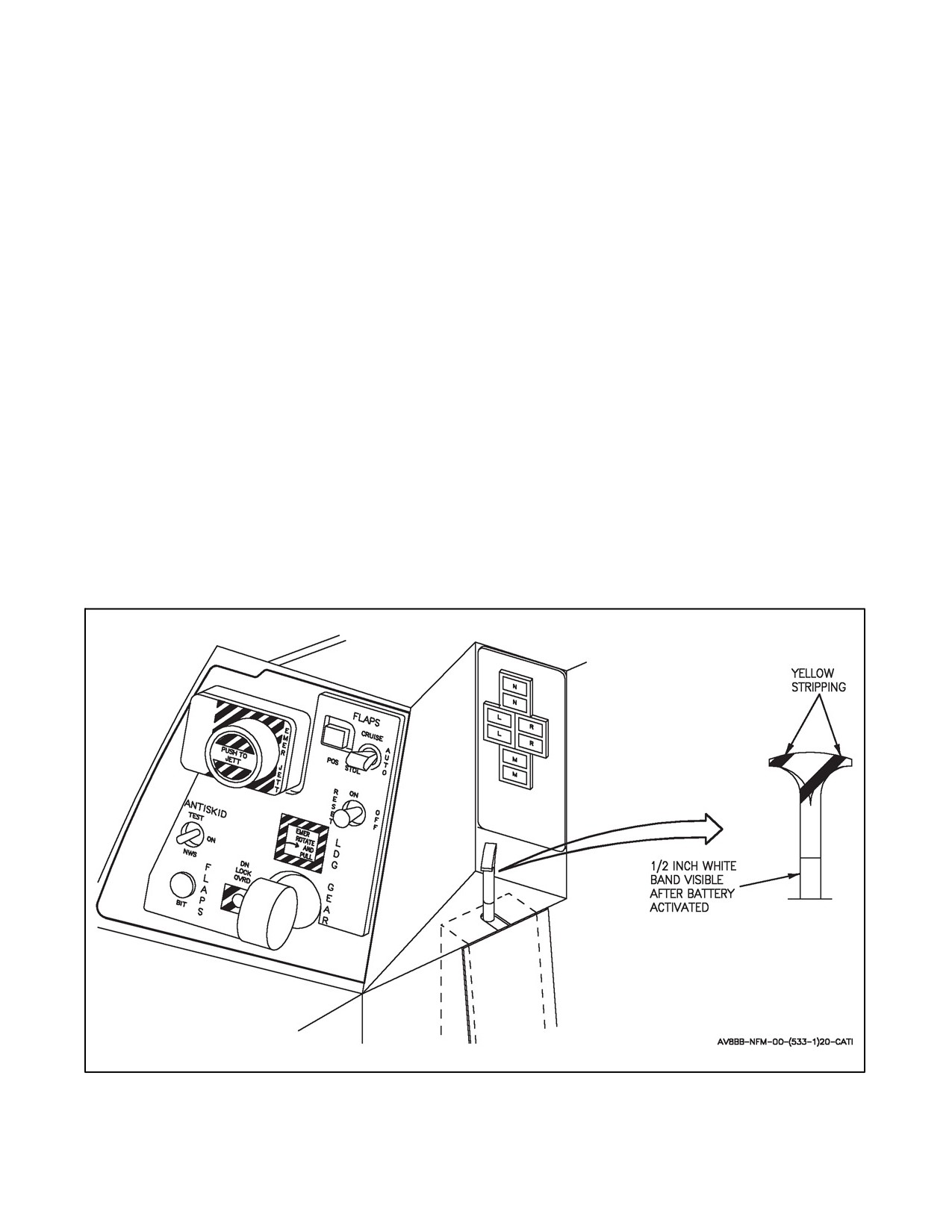
A1-AV8BB--NFM--000
handle up or handle down position. To select EMER, rotate the handle 90° clockwise and pull out to the stop. After
selecting EMER, the handle is locked in this position until maintenance restores normal operation.
DOWN - Extends landing gear.
UP - Retracts landing gear.
EMER - Rotated 90° cw and pulled. Actuates emergency pneumatic system to extend landing gear.
2.17.1.5 Emergency Landing Gear Handle (TAV--8B)
The emergency landing gear handle is located on the lower left main instrument panel and provides emergency
extension of the landing gear from the rear cockpit. The handle is lever locked in the up (normal) and down
(emergency) positions. When emergency is selected the landing gear handle in the front cockpit is disabled. To select
emergency, pull the handle out and set to down position. The normal position can be selected from the emergency
position by pulling handle out and setting to the up position, however, the landing gear will remain in the extended
position by emergency nitrogen/helium pressure.
2.17.1.6 LDG Gear Emergency Battery
(AV--8B 164151 and up, also AV--8B 161573 through 164150, TAV--8B 162747 through 164542 after AFC--328).
The LDG gear emergency battery is located on the left console below the landing gear position indicators. The battery
is a one shot device for the emergency extension of the landing gear when electrical power is lost. The battery must
be activated with the landing gear handle in the EMER position in order for the pneumatic system to extend the
landing gear. The battery is activated by extending a pull shaft upward approximately 1/2 inch. The pull shaft is
mechanically locked to prevent reseating of the handle. A 1/2 inch band of white paint on the exposed portion of the
rod provides a visual indication that the battery has been actuated. After selection, maintenance must replace the
battery. See Figure 2-16 for landing gear emergency battery.
Figure 2-16. Landing Gear Emergency Battery
2-57
ORIGINAL
A1-AV8BB--NFM--000
2.17.1.7 DN Lock OVRD Button
The DN LOCK OVRD button is on the lower left main instrument panel to the left of the landing gear handle. Pressing
the DN LOCK OVRD button disengages the mechanical downlock stop and permits the landing gear handle to be
set to the up position with aircraft weight on the main landing gear.
2.17.1.8 Landing Gear Position Indicators
The landing gear position indicators are on the lower left main instrument panel. The N (nose gear), L (left wing gear),
R (right wing gear) and M (main gear) green indicators come on when the respective gear is down and locked. The
N,L, Rand Mamberindicatorsarein--transitindicators andcomeonwhen therespectivegearis notdown andlocked
or up and locked. The N amber indicator will remain on if the nose gear is up and the nose gear doors are not closed.
2.17.1.8.1 Landing Gear Warning Lights and Aural Tone
The landing gear warning lights consist of the GEAR light on the upper right main instrument panel and the light
in the landing gear handle. Both warning lights are red and come on simultaneously. The warning lights come on
steady when any gear position disagrees with the landing gear handle position or with the landing gear up and either
nose gear door is not closed. The warning lights and the N (nose gear) amber position indicator will both be on when
the nose gear is up and either nose gear door is not closed. With the gear down and locked, improper door position
will not cause the warning lights to illuminate.
With the landing gear handle in the up position both warning lights will flash and the aural tone will sound in the
pilot’s head set when the aircraft altitude is below 6,000 feet, airspeed is less than 160 knots and the sink rate is over
250 feet per minute. On TAV--8B 163856 and up, AV--8B 163519 and up, a LANDING GEAR, LANDING GEAR
voice warning is provided in conjunction with the flashing GEAR warning lights.
2.17.1.8.2 Landing Gear Warning Lights (TAV--8B)
The landing gear warning lights operate as described for the AV--8B when the emergency landing gear handle is in
the normal (up) position. When the emergency landing gear handle is set to emergency, the warning lights come on
if any gear is not down and locked regardless of the landing gear handle (forward cockpit) position.
2.17.2 Emergency Pneumatic System
The pneumatic system consists of a single, hermetically sealed nitrogen/helium bottle, located in the main wheelwell,
and provides the pneumatic power for emergency extension of the landing gear. When emergency gear extension is
selected, the nitrogen/helium is released by ignition of an electrical pyrotechnic cartridge in the valve mounted on
the bottle. This valve releases pressurized nitrogen/helium into the landing gear actuators only and also seals the
pneumaticsystem.VariousothervalvesoperatetoisolatethepneumaticsystemfromtheHyd1system. Anadditional
feature of the system is an external indicator on the bottle that pops out when pressure falls below 2,400 psi. This
would normally indicate a low charge in the bottle. Once the emergency system is activated the emergency gear
extension handle is locked in the emergency position and cannot be reset by the pilot.
2.17.3 Nosewheel Steering (Before AFC 391)
The nosewheel steering (NWS) system is an electro--hydraulic operated system that provides directional control for
ground operations in three modes: steer, caster and center. The steering mode has a range of 45° left and right. A
hydraulic shutoff valve blocks off hydraulic flow to the steering motor when this range is exceeded. The hydraulic
flow is returned when the gear is back within the proper steering angle. The caster mode has a range of 179° left or
right. Mechanical stops are used to contain this range. The center mode is automatic when UP is selected with the
landing gear handle. The nosewheel will automatically steer to a center position at which point landing gear retraction
will commence.
Rudder pedal movement is transmitted to the nosewheel steering input on the nose landing gear (NLG)via aselector
actuator and a non--linear/vernier mechanism in the flight controls. With steering deselected, the selector actuator is
retracted and pedal inputs are not passed to the non--linear/vernier mechanism.
ORIGINAL
2-58
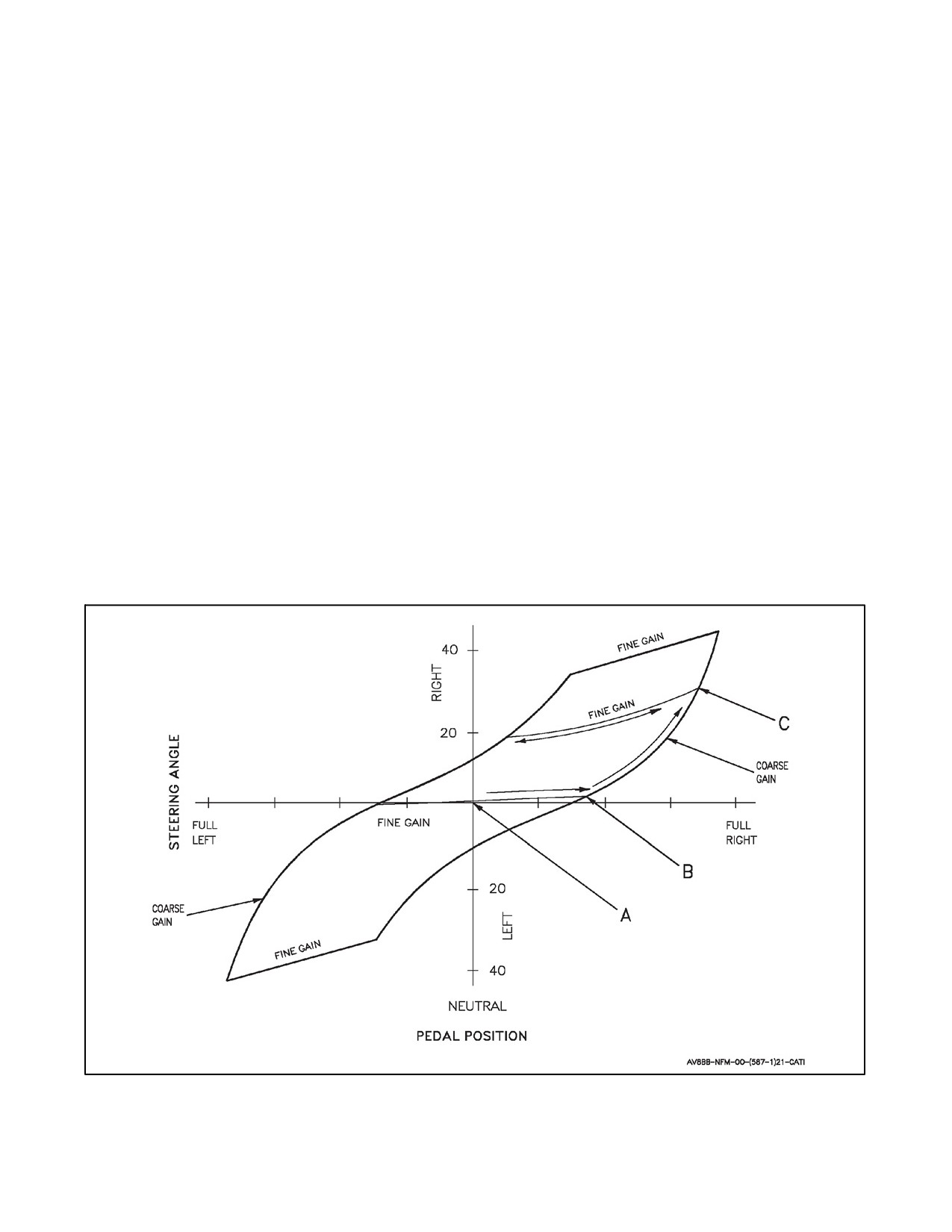
A1-AV8BB--NFM--000
The non--linear/vernier mechanism accommodates the requirements for a fine steering gain about neutral pedals for
runway operations and a maximum steering range of 45° L/R for minimum turn radius turns. The non--linear/vernier
mechanism provides a floating fine steering gain. When steering is initially selected, with rudder pedals neutral and
zero crab, the fine steering gain is centered about neutral pedals (point ‘A’ in Figure 2-17). This provides fine steering
control during landing rollouts. At approximately half pedal, fine steering ends (point ‘B’) and a coarse steering,
which takes the nosewheel to 45° left or right, starts. When pedal travel is reversed, steering is again in fine steering
(point ‘C’) which allows for precise steering control on taxiways and tight quarters. Note that after an excursion into
the coarse steering, neutral pedals will likely not produce 0° steering angle. To regain 0° steering angle at neutral
pedals, the system must be reset by deselecting nosewheel steering, letting the nosewheel caster to center (zero crab),
neutralizing the pedals and reselecting nosewheel steering.
Steering selection technique is critical to eliminating a transient nosewheel steering output during landing rollout.
Rudder pedals should be neutralized prior to steering selection as the nosewheel steering system will immediately
move to the commanded rudder pedal position when steering is selected. Selecting steering at other than neutral
pedals may result in a rapid heading change that can be towards or away from the desired direction of travel. Also,
crab angle, while on the runway, must be eliminated or reduced as much as possible when selecting steering. Selecting
nosewheel steering while crabbed will result in a steering output away from the desired direction of travel.
With antiskid system on, the nosewheel steering system is controlled by a two position springloaded switch on the
stick grip. With the gear down, pressing the switch selects nosewheel steering. With the gear down and the antiskid
system off, nosewheel steering operates at all times on the ground and in the air. In both these conditions thesteering
motor is controlled by rudder pedal movement. When the selector switch is released with the antiskid on, the nose
wheel is free to swivel about an arc of ±179° from center and rudder pedal movement is isolated from the system.
A SKID light, on the caution light panel, comes on to indicate failure of nosewheel castering. However, this is adual
function light and a determination must be made as to type of failure, caster or antiskid. Refer to Part V, paragraph
16.3.1 for failure mode determination.
Figure 2-17. Steering Gain (Before AFC--391)
2-59
ORIGINAL
A1-AV8BB--NFM--000
On TAV--8B 163860 and up, AV--8B 163677 and up, a CAUTION, CAUTION voice warning is also provided in
conjunction with the SKID light.
Hydraulic power is normally provided by the Hyd 1 system. In the event that Hyd 1 pressure drops to less than 1,400
psi, the aircraft is on the ground and nosewheel steering is selected, a switching valve will cause the system to be
powered by Hyd 2 pressure. The Hyd 2 accumulator will provide about 3 cycles (neutral to 3° L to 3° R and back
to neutral) of nosewheel steering if both hydraulic pumps fail. If power is lost to the Essential 28 Vdc bus (i.e., DC
caution light ON) then the antiskid will fail and nosewheel steering will be on at all times.
2.17.4 Nosewheel Steering (After AFC 391)
The nosewheel steering system is an electrohydraulic operated system that provides directional control for ground
operations with three modes: caster, lo gain steering and hi gain steering. A fourth steering mode, centered, is used
for gear retraction. Lo gain steering has a range of 14° left and right while hi gain steering provides 45° left and right.
The caster mode has a range of 179° left and right. Mechanical stops are used to contain this range. When the landing
gear handle is placed in the up position, the nosewheel will automatically steer to the center position at which time
landing gear retraction will commence.
Rudder pedal movement is transmitted to the nosewheel steering input on the NLG via a ratio changer actuator and
bellcrank in the nosewheel bay. With the actuator retracted, pedal movement is ratioed down to produce a 14° steering
input to the NLG. With the actuator extended, pedal movement is ratioed up to produce a 45° steering input to the
NLG.
In a TAV--8B, the front cockpit NWS button can command high or low gain steering normally with the exception
thatitcanbeoverriddenbytherearcockpit.Therearcockpit switchin aTAV--8B cannotselect highgain NWS.When
the nosewheel steering button is selected in the rear cockpit low gain steering will be enabled. If both the front cockpit
and rear cockpit switches are pressed the rear cockpit switch will override the front cockpit selection enabling low
gain steering.
With the landing gear handle DOWN, the nosewheel steering mode is controlled by the antiskid switch and the
undesignate/nosewheel steering button on the stick grip. With antiskid set to ON, caster mode is selected. With
antiskid set to NWS, lo gain steering is selected. Pressing the stick button increases the steering mode by one gain
such that with antiskid on, pressing the stick button produces lo gain steering and with antiskid set to NWS, pressing
the stick button produces hi gain steering.
Hi gain steering is undesirable above 20 KGS due to poor directional control characteristics. A Hi Gain Lockout,
actuated by throttle position, has been added to deselect hi gain steering if it has been inadvertently selected during
takeoff. If hi gain steering has been selected, advancing the throttle to approximately midway between IDLE and
MAX (approximately 75 percent fan speed) will automatically select lo gain steering. Hi gain steering will
automatically be reselected when the throttle is reduced through the mid point. The hi gain lockout feature has no
affect when either lo gain steering or caster mode has been selected.
HUD indications provide cues as to steering position and mode. Whenever the nosewheel is within 3° of neutral, a
C will appear inside the sideslip ball. A steering mode indication is provided in the lower right hand corner of the
HUD. Display computer logic determines which mode the steering system is in via inputs from hydraulic pressure
switches and relays. The indications are:
CTR - Centered.
CAST - Caster.
NWS - Lo gain.
NWS HI - Hi gain.
Illumination of NWS light on the caution/advisory panel is an indication of a NWS system failure. NWS failure mode
is ascertained by comparing the mode selected by the pilot with the mode displayed on the HUD. If CAST displayed
in the HUD with ANTISKID switch ON, engaging NWS button will result in either HI gain or centered steering
mode. If NWS displayed in HUD with ANTISKID switch on, caster mode has failed to LO gain NWS (“hot” NWS)
and will remain in LO gain when the NWS button is engaged. The mode displayed on the HUD is the active steering
mode.
ORIGINAL
2-60
A1-AV8BB--NFM--000
Hydraulic power is normally provided by the Hyd 1 system. In the event that Hyd 1 pressure drops to less than 1,400
psi, the aircraft is on the ground, and nosewheel steering is selected, a switching valve will cause the system to be
powered by Hyd 2 pressure. The Hyd 2 accumulator will provide about 3 cycles (neutral to 3° L to 3° R and back
to neutral) of nosewheel steering if both hydraulic pumps fail. Electrical power is provided by the emergency bus.
In the event that all electrical power is lost, including the battery, the steering system will revert to lo gain steering.
2.17.5 Lift Improvement Device System
The lift improvement device system (LIDS) is part of the landing gear system. The LIDS, composed of fixed strakes
and a retractable fence, increase the vertical lift 1,200 pounds by directing the jet fountain energy and reducing hot
air reingestion in ground effects. The LIDS fence extends into the airstream and is powered and held up by Hyd 1
pressure. Mechanically actuated locks hold the fence in the retracted position with Hyd 1 loss. The fence normally
extends and retracts with the landing gear. However, the fence may be retracted to reduce conventional takeoff drag
with the LIDS switch. Fence retraction is automatic above 125 knots.
A LIDS light on the caution light panel indicates that the landing gear selector handle and fence position do not agree,
the LIDS fence is down above 125 knots, is up below 125 knots or is unlocked with the gear handle up and the LIDS
retracted. If the air data computer fails, the 125 knot auto extend/retract is lost and, the LIDS will operate with the
gear.
2.17.5.1 LIDS Switch
The LIDS switch (fwd cockpit only) is located on the pilot’s services panel on the left console and is a two position
lever--locked switch.
RET - Retracts LIDS fence.
NORM - LIDS fence operates normally.
2.17.6 Brake System
The twin--wheel main landing gear is equipped with hydraulic operated carbon disc brakes. An antiskid system and
parking brake are also incorporated into the brake system. Both brakes operate simultaneously and progressively as
either brake pedal is depressed. Cables from each brake pedal and the parking brake lever operate a common cable
to the brake control valve. Hydraulic pressure is supplied by the Hyd 1 system. A nitrogen charged accumulator
provides limited hydraulic pressure for normal and antiskid braking if Hyd 1 pressure is not available. Two pressure
indicators adjacent to the inboard side of the caution light panel, provide information on brake accumulator pressure,
and applied brake pressure. The brake accumulator usable pressure range is 3,000 to 1,000 psi. When accumulator
pressure drops below 1,000 psi, braking power is lost. The brakes are limited in the amount of energy they can absorb
and dissipate in the form of heat without damage. The amount of heat added to the brakes for each braking effort
during taxi--out and rejected take--off or a landing rollout and taxi--in is cumulative and is a function of the speed of
the aircraft and its gross weight at the time the brakes are applied. The heat generated in the brakes is transferred to
the wheel and tire and (depending on the severity of the stop) can cause the tire pressure to rise to dangerous levels.
Thermal fuseplugs withinthewheelaredesignedto preventwheel explosionby relievingpressurefromthetirewhen
the wheels attains a particular temperature. There are no brake pressure or hydraulic pressure indicators in the rear
cockpit.
2.17.6.1 Parking Brake
The parking brake handle is located outboard of the throttle (fwd cockpit only). When the throttle is in idle the handle
can be moved into the parking detent. The throttle cannot be advanced until the parking brake is released from the
detent.
Actuation of the parking brake applies brake pressure in the system. Ensure the aircraft is properly secured (chained
or chocked as required) after shutdown as brake pressure will bleed off within approximately 3 hours to a level that
is insufficient to keep the aircraft in place.
2-61
ORIGINAL