EA-18G. FLIGHT MANUAL (2008) - page 12
A1-E18GA-NFM-000
AIR REFUELING
SIGNAL
MEANING
RESPONSE
DAY
NIGHT
One finger turn-up sig-
By receiver: start tur-
Tanker execute. Re-
nal.
bine.
ceiver gives thumbs-up
when turbine starts.
Form cone-shape with
Tanker execute. Re-
hand, all fingers ex-
ceiver give thumbs-up if:
tended aft (make signal
close to canopy).
1. Cone moved aft
1. By receiver: extend
1. Drogue extends
drogue.
properly.
2. Cone moved for-
2. By receiver: retract.
2. Drogue retracts
ward
fully and air turbine
feathers.
Make hand into cup-
By tanker: I am going to
By receiver: Nod. Give
shape, then make re-
dump fuel.
thumbs-up when fuel
peated pouring motions.
dumping commences.
Slashing motion of index
By tanker: I have
By receiver: Give
finger across throat.
stopped dumping fuel.
thumbs-up if fuel dump-
ing has ceased
Figure 26-1. Visual Communications (Sheet 9 of 9)
VII-26-9
(Reverse Blank)
ORIGINAL
A1-E18GA-NFM-000
CHAPTER 27
Deck/Ground Handling Signals
Communications between aircraft and ground personnel are visual whenever practical, operations
permitting. The visual communications chapters of Aircraft Signals NATOPS Manual (NAVAIR
00-80T-113) should be reviewed and practiced by all flightcrew and ground crew personnel. For ease
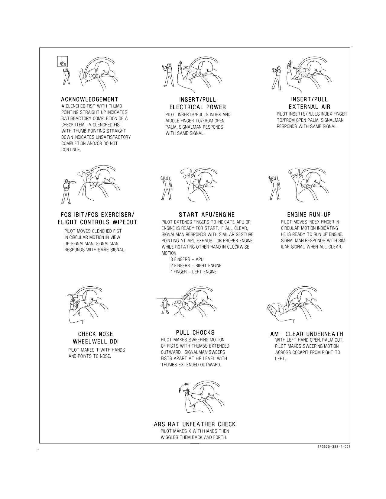
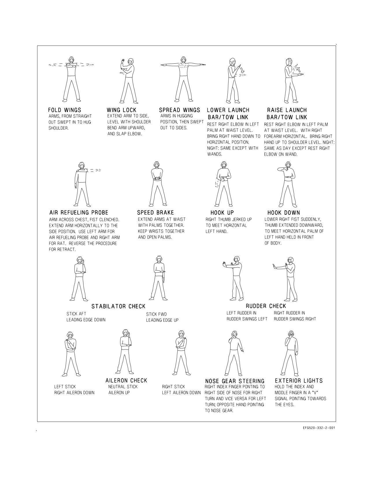
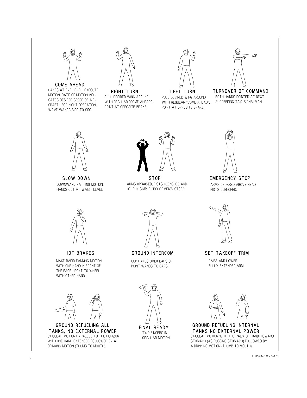
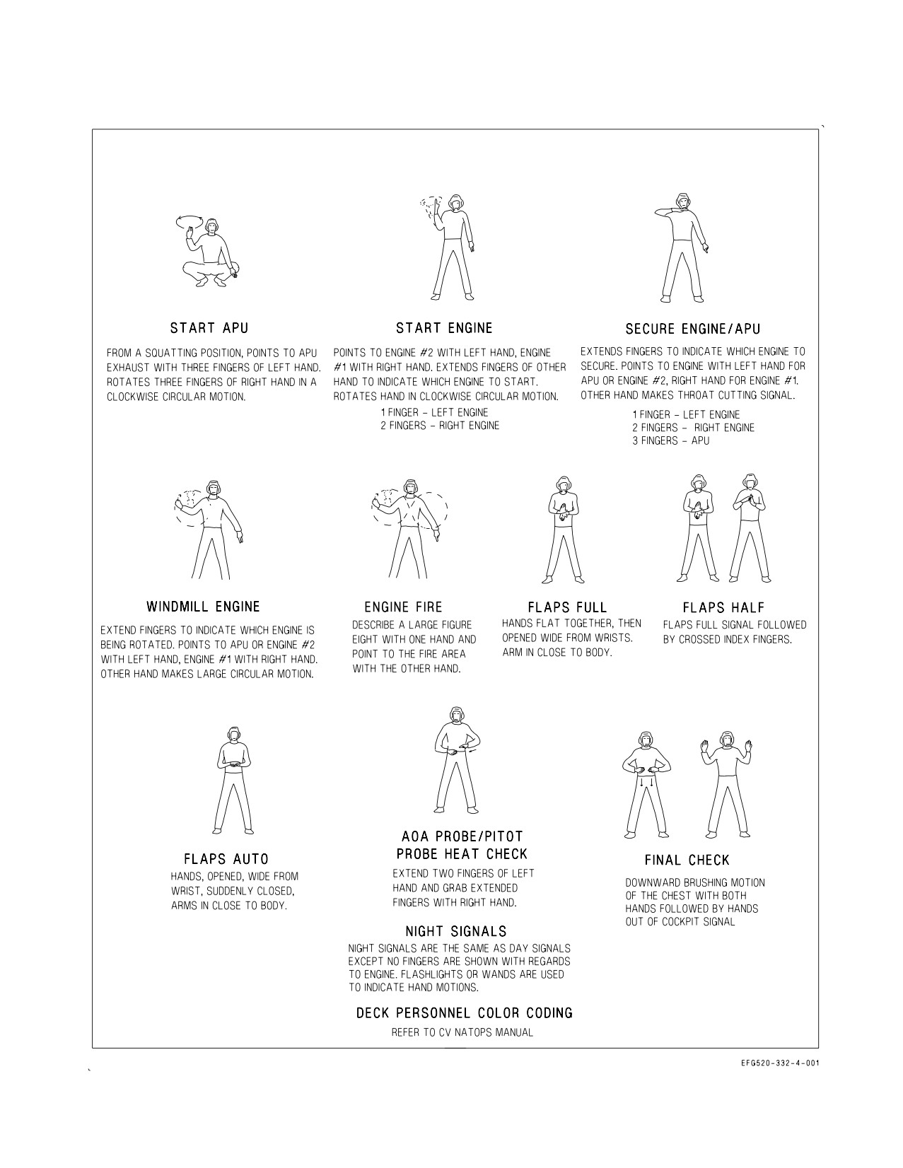
of reference, visual signals applicable to deck/ground handling are listed in Figure 27-1. During night
operations, wands shall be substituted for hand and finger movements.
VII-27-1
ORIGINAL
A1-E18GA-NFM-000
Figure 27-1. Deck Ground Handling Signals (Sheet 1 of 4)
VII-27-2
ORIGINAL
A1-E18GA-NFM-000
Figure 21-1. Deck Ground Handling Signals (Sheet 2 of 4)
VII-27-3
ORIGINAL
A1-E18GA-NFM-000
Figure 27-1. Deck Ground Handling Signals (Sheet 3 of 4)
VII-27-4
ORIGINAL
A1-E18GA-NFM-000
Figure 27-1. Deck Ground Handling Signals (Sheet 4 of 4)
VII-27-5
(Reverse Blank)
ORIGINAL
A1-E18GA-NFM-000
PART VIII
WEAPONS SYSTEMS
Refer to NTRP 3-22.2-EA-18G (EA-18G Classified Manual) for information on weapons systems.
69
(Reverse Blank)
ORIGINAL
A1-E18GA-NFM-000
PART IX
FLIGHT CREW COORDINATION
Chapter
28 - Aircrew Coordination
Chapter
29 - Crew Coordination Standards
71
(Reverse Blank)
ORIGINAL
A1-E18GA-NFM-000
CHAPTER 28
Aircrew Coordination
28.1 DEFINITION
Aircrew coordination is the use and integration of all available skills and resources to collectively
achieve and maintain flight efficiency, situational awareness, and mission effectiveness.
28.2 CRITICAL SKILLS OF AIRCREW COORDINATION
28.2.1 Situation Awareness. The degree of accuracy by which one’s perception of the current
environment mirrors reality. It is the ability to identify the source and nature of problems, extract and
interpret essential information, maintain an accurate perception of the external environment, and
detect a situation requiring action. Mission accomplishment depends on the level of situational
awareness of all members of the flight and of outside agencies.
28.2.2 Assertiveness. An individual’s willingness to actively participate, state, and maintain a
position until convinced by the facts that the other options are better.
28.2.3 Decision-Making. The ability to choose a course of action using logical and sound judgment
based on available information. Effective decision making requires assessing the situation, verifying
information, identifying solutions, anticipating the consequences of decisions, making the decision,
informing others of the decisions and rationale, and evaluating the decision. Good decisions optimize
risk management and minimize errors. Poor decisions can increase errors, lead to mission failure, and
are a leading cause of mishaps.
28.2.4 Communication. The ability to clearly and accurately send and acknowledge information,
instructions, or commands and provide useful feedback. Effective aircrew communication skills ensure
timely transfer and assimilation of accurate information and provide useful feedback. Open, profes-
sional communication that avoids defensiveness and encourages accurate understanding of the
intended message is critical to information flow in the flight. Aviators should be aware of the basic
sociological, psychological, and environmental barriers to communications, and attempt to overcome
them.
28.2.5 Leadership. The ability to direct and coordinate the activities of other crewmwmbers or
wingmen, and to stimulate the flight to work together as a team. The ultimate responsibility for safety
of flight rests with the aircraft commander/pilot in command; however, every crewmember has a
responsibility for safety of flight, compliance with NATOPS and SOP, and mission accomplishment.
Within the chain of command each crewmember must exercise vigilance and support the aircraft
commander with timely recommendations and back up as directed.
28.2.6 Adaptability/Flexibility. The ability to alter a course of action based on new information,
maintain constructive behavior pressure, and adapt to internal and external environment changes. The
critical aspects are anticipating problems, recognizing and acknowledging any changes or abnormali-
ties, taking alternative actions, providing and asking for assistance, and interacting constructively with
flight members. The success of a mission depends on the ability to alter behavior and dramatically
manage flight resources to meet situational demands.
IX-28-1
ORIGINAL
A1-E18GA-NFM-000
28.2.7 Mission Analysis. The ability to develop short-term, long-term, and contingency plans; and to
coordinate, allocate, and monitor crew and aircraft resources. Effective planning leads to flight conduct
that removes uncertainty, increases mission effectiveness, and enhances safety.
28.2.8 Factors That Degrade Aircrew Coordination.
1. Fixation on one task to the detriment of others.
2. Confusion.
3. Violation of NATOPS/FLIGHT minimums.
4. Violation of SOP.
5. No one in charge.
6. No lookout doctrine.
7. Failure to meet mission/planning milestones.
8. Absence of communication.
28.3 FLIGHT MEMBER POSITIONS
28.3.1 Mission Commander. The mission commander shall be a qualified naval aviator or naval
flight officer designated by appropriate authority. The mission commander shall be responsible for all
phases of the assigned mission except those aspects of safety-of-flight which relate to the physical
control of aircraft and within the prerogatives of the pilot in command. In accomplishing this, the
mission commander may exercise command over a single naval aircraft or formations of naval aircraft.
The mission commander shall direct a coordinated plan of action and be responsible for effectiveness
of the mission. Mission commander responsibilities include, but are not limited to:
1. Allocation of assets.
2. Supervision and allocation of planning tasks.
3. Assessment of capabilities and limitations of the flight.
4. Establishment of go/no-go criteria.
5. Assignment of roles and responsibilities.
6. Assurance of compliance with applicable orders, directives, and ROE/ROC.
28.3.2 Pilot In Command. The pilot in command is the pilot of an individual aircraft. The pilot in
command is responsible for the safe, orderly flight of the aircraft and the well-being of the crew. In the
absence of direct orders from higher authority cognizant of the mission, responsibility for starting or
continuing a mission with regard to weather or any other condition affecting the safety of the aircraft
rests with the pilot in command. The pilot in command may also be mission commander or formation
leader when so designated.
28.3.3 Formation Leader. A formation of one or more naval aircraft shall be under the direction of
a formation leader who is authorized to pilot naval aircraft. The formation leader is responsible for the
IX-28-2
ORIGINAL
A1-E18GA-NFM-000
safe and orderly conduct of the formation. The status of each member of the formation shall be clearly
briefed and understood prior to takeoff. The formation leader may also be the mission commander
when so designated.
28.3.4 Weapon Systems Operator (WSO). The WSO is directly involved in all operations and weapon
systems employment of the EA-18G aircraft except actual control of the aircraft. The WSO integrates
with the pilot to collectively achieve and maintain crew efficiency, situational awareness, and mission
effectiveness. When designated as mission commander, the WSO is also responsible for all phases of
the assigned mission.
28.4 AIRCREW RESPONSIBILITIES BY FLIGHT PHASE
28.4.1 Mission Planning and Briefing. All members of the flight should be involved in the mission
planning process and must be familiar with the mission requirements prior to the brief. The flight brief
shall be conducted with all members of the flight present. Any supporting assets (such as GCI, fighter
escort, EW, etc.) shall be briefed face-to-face, if possible. Flights requiring special coordination or
control should also be briefed face-to-face. Each type of flight or phase of flight may require unique
briefing requirements.
28.4.2 Pretakeoff. Aircraft discrepancy book (ADB) review, preflight, prestart, and poststart evolu-
tions are conducted individually with the aid of ground maintenance crews (plane captains, trouble
shooters, ordnance handlers, etc.). Timing must be considered when coordinating operations with other
activities. Marshalling and taxi as a flight should be in order with special emphasis on FOD avoidance.
A minimum taxi interval should be emphasized for FOD considerations. During section taxi the
wingman should not focus on other tasks or get behind.
28.4.3 Takeoff/Departure. The following should be considered and briefed when conducting a
formation takeoff in addition to the typical takeoff considerations such as gross weight, performance,
and abort capability:
• Interval for FOD avoidance
• Staggered line-up for abort
• Crosswind handling characteristics
• Jet exhaust/turbulence patterns
• Abort criteria and configuration changes prior to IMC
• Wingman positioning
• Airspeed
• Runway length/conditions
• Abort speed/procedures
Departure procedures are dependent upon weather and mission requirements.
The following are some considerations that may require crew coordination:
• Clearance compliance
• Climb schedule and interval of multi-plane formations
• Weather avoidance or penetration
• Individual departure to join on top
28.4.4 Enroute. Enroute procedures may differ greatly depending on mission requirements.
IX-28-3
ORIGINAL
A1-E18GA-NFM-000
28.4.5 Recovery. Egress, approach, and landing operations are numerous and dependent upon
mission objectives, weather, and types of landing. The following elements should be considered and
may require aircrew coordination:
• Navigation and communication systems management
• Course rules and re-entry procedures
• Approach and landing weather
• Landing type and capabilities (e.g., gross weight, crosswind limitations, asymmetry limitations,
etc.)
• Fuel for normal and alternate recoveries
• Formation size and composition based upon maneuverability and landing area congestion
• Instrument recovery/penetration procedures (single aircraft and/or formation)
• Power and maneuvering margins for wing men
• Jet wash and turbulence avoidance
• Terminal control/LSO procedures
• Landing interval and priorities
• FOD avoidance during landing and taxi
• De-arming procedures
28.4.6 Mission Critique. Mission assessment is critical following a flight whether the mission was a
multi-aircraft strike, an FCLP period, or a functional check flight. A critical and credible debrief of
mission effectiveness improves future mission success and enhances aircrew and supporting agency
coordination. A proper debrief should provide flight members and supporting agencies with informa-
tion on strengths and weaknesses so that future training and mission planning can focus on problem
areas and exploitation of strong areas.
28.5 SPECIAL CONSIDERATIONS
28.5.1 Functional Checkflights. All requirements for functional checkflights are listed in
OPNAVINST 4790.2 (Series) and are to be performed using the applicable functional check flight
checklist. Crew coordination shall be in accordance with standard NATOPS procedures and apply
during the entire checkflight. EA-18G NATOPS Chapter 10 outlines checks to establish acceptance
standards for the systems peculiar to the EA-18G aircraft. All instrument and indicator readings,
warning lights, and radar and navigation displays in the rear cockpit shall be compared throughout the
flight with the corresponding information available from the front cockpit. Close crew coordination
ensures proper and correct utilization of all functional check flight procedures.
28.5.2 Formation Flights. Formation flights involving two or more aircraft require a high degree of
crew coordination to ensure mission accomplishment and to reduce mid-air collision potential.
28.6 EMERGENCIES
Mission planning and briefing should address contingencies which may affect the flight. Proper
planning minimizes the effect of deviations from the planned mission. The possibility of a mission
abort, or even the loss of an aircraft or aircrew, can be significantly reduced by anticipating critical
phases of flight and preparing for potential emergency situations. An example is the thorough brief of
bird strike emergencies and divert fields along a low-level navigation route. Part V contains procedures
to correct an abnormal or emergency condition. Modify these procedures as required in cases of
multiple emergencies, adverse weather, or other peculiar factors. Use common sense and sound
judgment to determine the correct course of action.
IX-28-4
ORIGINAL
A1-E18GA-NFM-000
CHAPTER 29
Crew Coordination Standards
29.1 PHILOSOPHY
EA-18G crews tactically employ the aircraft utilizing community-wide standards for task-
assignment and crew coordination. The EA-18G community’s disciplined and standardized approach
to crew coordination enables any combination of pilot and EWO to benefit from life-saving, individual
habit patterns while implementing a time-tested system of checks and balances.
Crews must approach EA-18G employment with an understanding that mission accomplishment
depends upon effective crew coordination and that crew coordination is an obligation equally shared.
The pilot is responsible for safety of flight, formation keeping, threat awareness, and weapons
employment. The EWO is responsible for avionics, weapons and sensors interface, communication, and
copilot duties. The most effective crews will complete their individual assignments while monitoring
the progress of the mission as a whole.
What follows are the crew coordination standards for administrative phases of flight. The
information contained herein is not meant to be used as a checklist, but should serve as a guide for
ensuring the aircrew work together effectively as a team. For tactical crew coordination standards, refer
to the Strike Fighter Squadron One Two Two Crew Coordination Standardization Manual.
29.2 MISSION PLANNING
Pilots and EWOs share mission planning responsibilities as delegated by the mission commander.
29.3 CREW BRIEFING
Individual crews shall discuss mission related coordination points and review relevant crew
coordination standards before each flight.
29.4 COMMUNICATIONS
Pilot
1. Make administrative inter-flight communications to include dressing the formation, fuel and g
checks, and configuration changes.
EWO
1. Change radio frequencies as required.
2. Perform all other non-administrative, inter-flight communications.
29.4.1 Intra-Cockpit Communications (ICS)
Crews will strive to fly with minimal ICS communication. Following crew coordination standards
and using standard EA-18G terminology and guidelines minimizes ICS requirements and builds
situational awareness.
IX-29-1
ORIGINAL
A1-E18GA-NFM-000
29.4.2 Guidelines for Effective Communications
• ICS communication regarding aircraft/aircrew survivability has priority over all other commu-
nications (ICS or radio).
• Use ICS Standard Communication Brevity Terms, delineated in paragraph 29.9, to minimize
and standardize ICS communication.
• Adjust ICS volumes and VOX sensitivities throughout flight so that administrative communi-
cations and tactical communications/tone (weapon/RWR) are appropriately balanced.
• Do not communicate via ICS over incoming or outgoing radio transmissions unless a safety of
flight or time-critical mission situation exists.
• Time ICS communications to allow the flight to gain/maintain SA via radio transmissions.
• Lead with directive communication and follow-up with descriptive communication.
• Limit descriptive communication during critical flight phases.
• Communicate visual acquisitions and lost sight situations ASAP.
• Communicate information pertinent to the entire flight via radio communications.
• Either aircrew may change the Master Mode, Bingo bug, or RALT setting, but must alert the
other crewmember of the change via ICS. Changes to navigation system by either crewmember
should also be enunciated.
29.5
PRE-FLIGHT
Pilots and EWOs shall both read the Aircraft Data Book. The pilot in command signs for the aircraft.
Whenever possible the crew will walk together to the aircraft. Both the pilot and EWO shall account
for the aircraft pins and verify the VDEDP codes are correct. After the VDEDP codes are verified, the
pilot and EWO will split apart to conduct individual pre-flight inspections in accordance with Chapter
7. The pilot will walk clockwise around the aircraft while the EWO will walk counter-clockwise. Notify
the other crewmember, as well as maintenance personnel, of any discrepancies found during the
inspection. Both the pilot and EWO shall verify all panels are closed before manning the aircraft.
29.6 FLIGHT PHASES
General
1. Both aircrew are responsible for maintaining lookout doctrine, to include terrain clearance, at all
times.
29.6.1 Start/Taxi/Takeoff
Pilot
1. Perform all checks in accordance with Chapter 7.
2. Report ″rolling″, ″saluting″, or ″lights on″, as appropriate during CV operations, to EWO.
IX-29-2
ORIGINAL
A1-E18GA-NFM-000
EWO
1. Perform all checks in accordance with Chapter 7.
2. Monitor engine instruments, airspeed, and runway remaining.
29.6.2 Departure
Pilot
1. Relay engine instrument readings to the EWO.
2. Advise the EWO of any abnormal aircraft issues or events.
3. Confirm assigned headings and altitudes with the EWO, if required.
4. Maintain proper lookout doctrine.
EWO
1. Copy and acknowledge all clearances.
2. Provide a departure brief after completing takeoff checks, but before taking the runway.
Departure brief will include departure and transition name, runway, departure heading, initial
altitude restriction, the first turn, and navigation system setup. If the first turn is an arc, add the arc
distance. After takeoff, the EWO shall update the pilot on the SID staying one step ahead so that the
pilot is neither getting too much information at once nor feels the need to reference the approach
plate.
3. During section takeoff, check engine instruments/aircraft status if in wing aircraft and monitor
the wingman’s airplane/position if in the lead aircraft.
4. Monitor airspeed and runway remaining.
5. Monitor instruments.
6. Maintain proper lookout doctrine.
7. Monitor the published or clearance departure procedures and alert the pilot to any significant
deviations from the prescribed heading, airspeed, or altitude.
29.6.3 Rendezvous and Formation
Pilot
1. Execute rendezvous.
EWO
1. Crosscheck the pilot on rendezvous mechanics (airspeed, angle of bank, altitude, closure rate,
relative bearing, and altitude separation).
IX-29-3
ORIGINAL
A1-E18GA-NFM-000
29.6.4 Cruise
Pilot
1. Maintain situational awareness of geographical position relative to divert fields.
2. Monitor fuel status, navigation systems, and frequencies assigned.
3. If experiencing vertigo/disorientation, notify the EWO immediately.
EWO
1. Maintain proper lookout doctrine.
2. Maintain an instrument scan.
3. Maintain navigation system.
4. Maintain situational awareness of geographical position relative to divert airfields along the route
of flight, winds at operating altitude, and bingo profile altitude.
5. Copy all clearances and acknowledge all heading/altitude changes.
6. Monitor fuel status.
7. If the pilot experiences vertigo/disorientation, carefully monitor instruments/HUD video and
inform pilot of attitude, altitude, and airspeed as required. Be prepared to direct the pilot how to
maneuver the aircraft back to a wings-level attitude.
29.6.5 Inflight Refueling
Pilot
1. Complete the air-refueling checklist in accordance with Chapter 9.
2. Ensure the amber light is visible before commencing approach.
3. Notify EWO of the position of the fuel switches prior to and after tanking.
4. After disengagement, stay behind the drogue until all members of the flight are sighted.
5. Complete the post-refueling checklist.
EWO
1. Acquire the tanker with aircraft sensors and visually.
2. Monitor azimuth, range, and closure during rendezvous.
3. Visually clear the immediate airspace around the tanker prior to maneuvering into pre-contact
position and prior to maneuvering from behind tanker when tanking is complete.
4. Monitor closure and advise the pilot if an unsafe condition is developing.
IX-29-4
ORIGINAL
A1-E18GA-NFM-000
5. Make required voice reports as briefed.
6. Count up every 1000 pounds of fuel over the ICS and report to pilot when fuel transfer is
complete.
7. Advise the pilot of unusual fuel spillage or unsafe probe/drogue conditions.
8. Verify status of fuel switches with pilot.
29.6.6 Approach
Pilot
1. Determine as a crew the type of approach desired with respect to existing weather.
2. Complete the descent/instrument penetration checklist.
3. Monitor UHF communication conducted by the EWO.
4. When executing a CCA, conform to procedures contained in this manual, CV NATOPS manual,
and approach control’s instructions.
5. Confirm headings and altitudes with the EWO as required.
6. Advise the EWO if the fuel dump switch has been activated/deactivated.
7. Advise the EWO if experiencing vertigo/disorientation.
EWO
1. Determine as a crew the type of approach desired with respect to existing weather.
2. Verify the descent/instrument penetration checklist complete.
3. Whenever flying to an unfamiliar field, EWOs will give the pilot a field brief. Field briefs will
include field elevation, runway description, approach lighting, TACAN location, arresting gear, and
minimum safe altitude.
4. Alert the pilot to significant deviations from published/assigned course or altitude.
5. Maintain situational awareness to the ship’s/field position relative to bingo fuel.
6. Decrement the HSI range scales at approximately 20 and 10 nautical miles and set courseline to
appropriate runway heading.
7. Aid in planning holding/marshall entry and pattern timing.
8. Monitor altitude, attitude, and airspeed during holding, penetration, and approach.
IX-29-5
ORIGINAL

A1-E18GA-NFM-000
9. Provide a timely approach brief as described in figure 29-1.
Approach Type
Approach Brief
Missed Approach
Precision
Airfield name, runway, final ap-
Give the initial heading, altitude
(Prior to enroute descent)
proach course, and decision
restriction, and first turn.
height.
Update missed approach instruc-
Non-Precision
Airfield name, approach name,
tions staying one step ahead
(Prior to the initial approach fix) runway, initial approach fix, ini-
thereafter.
tial heading, and initial altitude
restriction.
Visual
VFR course rules.
(Prior to the initial point)
Figure 29-1. Approach Briefs
10. Monitor the appropriate approach plate and advise pilot of required heading and altitude
changes as prescribed by the approach.
11. Report to the pilot during penetration and/or descents through each 5000 feet of altitude above
5000 feet AGL and each 1000 feet below 5000 feet AGL, until reaching the desired altitude.
12. Monitor the fuel quantity when dumping.
13. Be prepared to talk down the pilot through distance/altitude checkpoints when executing a CCA
utilizing radar, TACAN, and INS/GPS (i.e., during a self-contained emergency approach).
14. Inform the pilot when changing radio, TACAN, or IFF.
29.6.7 Landing
Pilot
1. Perform the landing checklist in accordance with Chapter 7.
EWO
1. Monitor traffic pattern entry altitude and airspeed as prescribed by local course rules or CV
NATOPS Manual, while maintaining a proper lookout doctrine and assisting the pilot in determin-
ing the interval.
2. Verify landing checklist completion in accordance with Chapter 7.
3. Calculate on-speed.
4. Make UHF transmissions.
5. Be alert for, and report traffic to the pilot.
IX-29-6
ORIGINAL
A1-E18GA-NFM-000
6. On roll-out be prepared to advise of arresting gear location (field landing).
7. Report to the pilot airspeed in conjunction with runway remaining if prudent to do so.
29.6.8 Post Flight
Pilot
1. Perform post flight checks in accordance with Chapter 7.
2. Download MU/maintenance card.
EWO
1. Perform post flight checks in accordance with Chapter 7.
2. Advise pilot when ready for shutdown.
3. Complete NALCOMIS.
29.7 DEBRIEFING
Mission Commander
1. Conduct a thorough debrief to include specific comments on errors and techniques, and review
procedures for correcting/improving them.
Formation Leader/Mission Commander
1. Conduct a thorough flight debrief.
29.8 SPECIAL CONSIDERATIONS
29.8.1 Functional Check Flights
PMCF aircraft demand closer scrutiny than normal during aircraft discrepancy book screening,
preflight, flight, and postflight maintenance debriefing. During the flight brief, the PMCF aircrew
should give special attention to briefing those malfunctions or emergencies that are more likely to occur
as a result of a maintenance action taken.
29.8.2 Emergencies
The primary responsibility of the aircrew during the resolution of an aircraft malfunction or
emergency is to fly the aircraft safely. During an emergency, the assistance of the EWO is of the utmost
value. After backing up the pilot on completion of NATOPS boldface procedures, the EWO should
review the appropriate emergency checklist with the pilot while monitoring the flight performance of
the aircraft. It is recommended a challenge-reply format be used for working through the checklist and
it is important the EWO set a pace that ensures no steps are missed.
Pilot
1. Maintain safe control of the aircraft.
2. Perform the boldface procedures.
IX-29-7
ORIGINAL
A1-E18GA-NFM-000
3. Perform emergency procedures as challenged by the EWO.
4. Ensure aircraft is properly configured for emergency landing (if applicable).
EWO
1. Monitor flight performance.
2. Initiate challenge and reply procedures utilizing PCL. (Review all boldface procedures to ensure
appropriate actions are complete.)
3. Summarize Notes, Warnings, and Cautions that apply to the emergency.
4. Configure navigation system for emergency divert, as applicable.
5. Coordinate with air traffic controllers as required.
29.9 STANDARD ICS TERMS
Refer to figure 29-2 for standard ICS terms.
Terms
Action(s)
″FIRE TEST″
PILOT IS INITIATING THE FIRE TEST SWITCH. EX-
PECT TO SEE FIRE/APU/BLEED LIGHTS WITH VOICE,
TWICE.
″GOOD WAYPOINT 0″
IMPLIES GOOD WAYPOINT 0 AND MAGVAR. USED
WHEN NOT USING THE WAYPOINT 0 LOADED ON
THE MU. SHORE OPS ONLY.
″CANOPY″
PILOT CALL BEFORE RAISING OR LOWERING THE
CANOPY. LISTEN FOR ″CLEAR″ OR ″STANDBY″ FROM
EWO.
″FOUR DOWN″
PILOT IS ACCOMPLISHING THE FOUR DOWN POR-
TION OF NATOPS CHECKS. HANDS ABOVE THE
CANOPY RAIL IF IN F(T).
″MOVING″
PILOT INFORMATIVE CALL THAT THE AIRCRAFT IS
TAXIING.
″ORDIES″
BOTH AIRCREW HANDS UP FOR WEAPON ARMING.
Figure 29-2. Standard ICS Terms (Sheet 1 of 3)
IX-29-8
ORIGINAL
A1-E18GA-NFM-000
Terms
Action(s)
″FENCE COMPLETE″, ″FENCE
INFORMATIVE THAT ALL THE AIRCREW’S SYSTEMS
COMPLETE, EXCEPT __″
ARE SET ACCORDING TO STAN/BRIEF. IMPLIES
READY FOR TAXI. NORMALLY EWO REPORTS FIRST
AFTER DOUBLE CHECKING THE EW SUITE IF RE-
QUIRED.
″WINGS″
PILOT CALL BEFORE SPREADING OR FOLDING
WINGS. LISTEN FOR ″CLEAR″ OR ″STANDBY″ FROM
EWO.
″SEATS″
CALL TO EITHER SAFE OR ARM EJECTION SEATS.
FOR BOTH SAFING AND ARMING THE SEATS, WHO-
EVER INITIATES THE CALL, THE OTHER AIRCREW
MUST REPORT SAFE OR ARMED FIRST.
″GOING FLYING″
PILOT CALL AT BRIEFED MAX ABORT SPEED ON
TAKEOFF ROLL.
″CONTINUE, (CAUTION)″
TAKEOFF ROLL CAUTION. EWO CALL AND OPINION
TO CONTINUE.
Ex: ″CONTINUE, MU LOAD″
″ABORT″
ABORT TAKEOFF, DIVE, ETC.
″CODES CHECKED″
EWO CALL THAT BOAS, BITS, MSP’S, AND FLIR CODES
CHECKED.
″GOOD UPDATE″
INS IS UPDATED.
″READY FOR SHUTDOWN″
INFORMATIVE CALL FROM EWO THAT ALL ELECTRI-
CAL EQUIPMENT IS OFF.
″SHUTTING DOWN″
INFORMATIVE CALL FROM PILOT THAT THE LAST
MOTOR IS BEING SHUT DOWN.
″COUPLED (WAYPOINT, TACAN
PILOT INFORMATIVE CALL THAT THE AIRCRAFT AU-
SEQUENCE)″
TOPILOT IS COUPLED TO WHAT IS MENTIONED.
Note: Also shows on the advisories.
″UNCOUPLE(D) (WAYPOINT,
DIRECTIVE TO UNCOUPLE OR INFORMATIVE THAT
TACAN, SEQUENCE)″
THE AIRCRAFT IS UNCOUPLED FROM THE AUTOPI-
LOT.
Figure 29-2. Standard ICS Terms (Sheet 2)
IX-29-9
ORIGINAL
A1-E18GA-NFM-000
Terms
Action(s)
″YOUR (SENSOR, AVIONICS,
DIRECTIVE FOR OTHER AIRCREW TO OPERATE THE
MENU, ETC.)″
SPECIFIED DISPLAY/SENSOR. INITIATING AIRCREW
IS RELINQUISHING CONTROL.
Ex: ″YOUR RADAR″, ″YOUR TDC″, ″YOUR HSI″
″MY (SENSOR, AVIONICS,
I AM OPERATING THE SPECIFIED DISPLAY/SENSOR.
MENU, ETC.)″
Ex: ″MY RADAR″, ″MY FLIR″, ″MY HSI″
″CHECK (SENSOR, AVIONICS,
PIMP OTHER AIRCREW TO CHECK WHAT IS SPECI-
MENU, ETC.)″
FIED.
Ex: ″CHECK AZ/EL″, ″CHECK ALE-47 PROGRAM″,
″CHECK ALTITUDE″
″SET (SENSOR, AVIONICS,
DIRECTIVE FOR OTHER AIRCREW TO SET WHAT IS
MENU, ETC.) ___″
SPECIFIED.
Ex: ″SET RADALT 450″, ″SET 35 ALPHA″
″(SENSOR, AVIONICS, MENU,
INFORMATIVE TO OTHER AIRCREW.
ETC.) SET ___″
Ex: ″RADALT SET 450″, ″BINGO SET 3.5″, ″STORES SET″,
″ALTIMETER SET 2992″, ″EW SUITE SET″
Note: Mandatory ICS calls when changing Bingo, Radalt, or
Altimeter.
″CYCLE (WEAPON, AVIONICS,
DIRECTIVE TO CYCLE OFF AND ON WHAT IS
ETC.)″
REQUESTED.
Ex: ″CYCLE TACAN″
″GO (RADAR MODE, WEAPON,
DIRECTIVE FOR OTHER AIRCREW TO SELECT WHAT
MASTER MODE, ETC.)″
IS REQUESTED.
Ex: ″GO WINDER″, ″GO WACQ″, ″GO AIR TO GROUND″
″GOING (RADAR MODE,
INFORMATIVE THAT THE AIRCREW IS SELECTING
WEAPON, MASTER MODE,
WHAT IS STATED AFTER A SHORT PAUSE FOR OB-
ETC.)″
JECTIONS.
Ex: ″GOING WACQ″, ″GOING AIR TO GROUND″
Note: Mandatory ICS call before changing Master Modes
Figure 29-2. Standard ICS Terms (Sheet 3)
IX-29-10
ORIGINAL
A1-E18GA-NFM-000
PART X
NATOPS EVALUATION
Chapter
30 - NATOPS Evaluation
73
(Reverse Blank)
ORIGINAL
A1-E18GA-NFM-000
CHAPTER 30
NATOPS Evaluation
30.1 CONCEPT
The standard operating procedures prescribed in this manual represent the optimum method of
operating the EA-18G aircraft. The NATOPS Evaluation is intended to evaluate compliance with
NATOPS procedures by observing and grading individuals and units. This evaluation is tailored for
compatibility with various operational commitments and missions of both Navy and Marine Corps
units. The prime objective of the NATOPS Evaluation program is to assist the unit commanding
officer in improving unit readiness and safety through constructive comment. Maximum benefit from
the NATOPS Program is achieved only through the vigorous support of the program by commanding
officers as well as flight crewmembers.
30.1.1 Implementation. The NATOPS Evaluation program shall be carried out in every unit
operating naval aircraft. Pilots desiring to attain/retain qualification in the EA-18G shall be evaluated
initially in accordance with OPNAV Instruction 3710.7 series, and at least once during the twelve
months following initial and subsequent evaluations. Individual and unit NATOPS Evaluations are
conducted annually; however, instruction in and observation of adherence to NATOPS procedures
must be on a daily basis within each unit to obtain maximum benefits from the program. The NATOPS
Coordinators, Evaluators, and Instructors shall administer the program as outlined in OPNAVINST
3710.7 series. Evaluees who receive a grade of Unqualified on a ground or flight evaluation shall be
allowed 30 days in which to complete a reevaluation. A maximum of 60 days may elapse between the
date the initial ground evaluation was commenced and the date the flight evaluation is satisfactorily
completed.
30.1.2 Definitions. The following terms, used throughout this section, are defined as to their specific
meaning within the NATOPS program.
30.1.2.1 NATOPS Evaluation. A periodic evaluation of individual flight crewmember standardiza-
tion consisting of an open book examination, a closed book examination, an oral examination, and a
flight evaluation.
30.1.2.2 NATOPS Reevaluation. A partial NATOPS Evaluation administered to a flight crewmem-
ber who has been placed in an Unqualified status by receiving an Unqualified grade for any of his
ground examinations or the flight evaluations. Only those areas in which an unsatisfactory level was
noted need be observed during a reevaluation.
30.1.2.3 Qualified. A qualified evaluation means that a flight crewmember is well standardized and
demonstrates highly professional knowledge of and compliance with NATOPS standards and proce-
dures. Momentary deviations from or minor omission in non-critical areas are permitted if prompt and
timely remedial action is initiated by the evaluee.
30.1.2.4 Conditionally Qualified. A conditionally qualified evaluation means that a flight crewmem-
ber is satisfactorily standardized. One or more significant deviations from NATOPS standards and
procedures, but had no errors in critical areas and no errors jeopardizing mission accomplishment or
flight safety.
X-30-1
ORIGINAL
A1-E18GA-NFM-000
30.1.2.5 Unqualified. An unqualified evaluation means that a flight crewmember is not acceptably
standardized and fails to meet minimum standards regarding knowledge of and/or ability to apply
NATOPS procedures, one or more significant deviations from NATOPS standards and procedures
which could jeopardize mission accomplishment or flight safety.
30.1.2.6 Area. A performance area consisting of preflight, flight, or postflight.
30.1.2.7 Sub-area. A performance sub-division within an area, which is observed and evaluated
during an evaluation flight.
30.1.2.8 Critical Area/Sub-area. Any area or sub-area which covers items of significant importance
to the overall mission requirements, the marginal performance of which would jeopardize safe conduct
of the flight.
30.1.2.9 Emergency. An aircraft component, system failure, or condition which requires instanta-
neous recognition, analysis, and proper action.
30.1.2.10 Malfunction. An aircraft component or system failure or condition which requires recog-
nition and analysis, but which permits more deliberate action than that required for an emergency.
30.2 GROUND EVALUATION
30.2.1 General. Prior to commencing the flight evaluation, an evaluee must achieve a minimum
grade of Qualified on the open book and closed book examinations. The oral examination is also part
of the ground evaluation but may be conducted as part of the flight evaluation. To assure a degree of
standardization between units, the NATOPS instructors may use the bank of questions contained in
this section in preparing portions of the written examinations.
30.2.1.1 Open Book Examination. The open book examination shall consist of, but not be limited to,
the question bank. The purpose of the open book examination portion of the written examination is to
evaluate the knowledge of appropriate publications and of the aircraft.
30.2.1.2 Closed Book Examination. The closed book examination may be taken from, but not
limited to, the question bank and shall include questions concerning normal/emergency procedures
and aircraft limitations. Questions designated critical shall be so marked.
30.2.1.3 Oral Examination. The questions may be taken from this manual and drawn from the
experience of the Instructor/Evaluator. Questions should be direct and positive and should in no way
be opinionated.
30.2.1.4 OFT/WST Procedures Evaluation. An OFT may be used to assist in measuring flight
crewmember efficiency in the execution of normal operating procedures and reaction to emergencies
and malfunctions. In areas not served by an OFT, this may be done by placing the flight crewmember
in an aircraft and administering appropriate questions.
30.2.1.5 NAMT Systems Check. If desired by the individual squadron, Naval Air Maintenance
Trainer facilities may be utilized to evaluate flight crewmember knowledge of aircraft systems and
normal and emergency procedures.
30.2.1.6 Grading Instructions. Examination grades shall be computed on a 4.0 scale and converted
to an adjective grade of Qualified or Unqualified.
X-30-2
ORIGINAL
A1-E18GA-NFM-000
30.2.1.6.1 Open Book Examination. To obtain a grade of Qualified, an evaluee must obtain a
minimum score of 3.5.
30.2.1.6.2 Closed Book Examination. To obtain a grade of Qualified, an evaluee must obtain a
minimum score of 3.3.
30.2.1.6.3 Oral Examination and OFT Procedure Check (If Conducted). A grade of Qualified or
Unqualified shall be assigned by the Instructor/Evaluator.
30.3 FLIGHT EVALUATION
The flight evaluation should be conducted in an OFT but may be conducted on any routine syllabus
flight with the exception of flights launched for FCLP/CARQUAL training. Emergencies shall not be
simulated unless the flight is accomplished with a qualified IP in the rear seat.
The number of flights required to complete the flight evaluation should be kept to a minimum;
normally one flight. The areas and sub-areas to be observed and graded on a flight evaluation are
outlined in the grading criteria with critical areas marked by an asterisk (*). Sub-area grades shall be
assigned in accordance with the grading criteria. These sub-areas shall be combined to arrive at the
overall grade for the flight. Area grades, if desired, shall also be determined in this manner.
The areas and sub-areas in which flight crewmembers may be observed and graded for adherence to
standardized operating procedures are outlined in the following paragraphs.
NOTE
• If desired, units with training missions may expand the flight evalua-
tion to include evaluation of standardized training methods and
techniques.
• The IFR portions of the Flight Evaluation shall be in accordance with
the procedures outlined in the NATOPS Instrument Flight Manual.
30.3.1 Mission Planning/Briefing.
1. Flight Planning.
2. Briefing.
3. Personal Flying Equipment (*)
30.3.2 Preflight/Line Operations. Because preflight/line operations procedures are graded in detail
during the ground evaluation, only those areas observed on the flight check shall be graded.
1. Aircraft Acceptance
2. Start
3. Before Taxiing Procedures
X-30-3
ORIGINAL
A1-E18GA-NFM-000
30.3.3 Taxi.
30.3.4 Takeoff (*).
1. ATC (air traffic control) Clearance
2. Takeoff
30.3.5 Climb/Cruise.
1. Departure
2. Climb and Level-Off
3. Procedures Enroute
30.3.6 Approach/Landing (*).
1. Tacan, GCA, ILS/ACLS, Radar, ADF
2. Landing
30.3.7 Communications.
1. R/T Procedures
2. Visual Signals
3. IFF Procedures
30.3.8 Emergency/Malfunction Procedures
(*).
In
this
area,
the
flight
crewmember
shall
be
evaluated only in the case of actual emergencies, unless evaluation is conducted in the OFT/WST or
EA-18G.
30.3.9 Post Flight Procedures.
1. Taxi
2. Shutdown
3. Inspection and Records
4. Flight Debriefing
30.3.10 Mission Evaluation. This area includes missions covered in the NATOPS Flight Manual and
NTRP 3-22.2-EA-18G (EA-18G Classified Manual) for which standardized procedures/techniques
have been deployed.
30.3.11 Applicable Publications. The NATOPS Flight Manual contains the standard operations
criteria for EA-18G aircraft. Publications relating to environmental procedures peculiar to shorebased
and shipboard operations and tactical missions are NTRP
3-22.2-EA-18G
(EA-18G Classified
Manual), NWPs, NWIPs, ATC/CATCC Manual, Local Air Operations Manual, and Ship Air
Operations Manual.
X-30-4
ORIGINAL
A1-E18GA-NFM-000
30.3.12 Flight Evaluation Grading Criteria. Only those sub-areas provided or required will be
graded. The grades assigned for a sub-area shall be determined by comparing the degree of adherence
to standard operating procedures with adjectival ratings listed below. Momentary deviations from
standard operating procedures should not be considered as disqualifying provided such deviations do
not jeopardize flight safety and the evaluee applies prompt corrective action.
30.3.13 Flight Evaluation Grade Determination. The following procedure shall be used in deter-
mining the flight evaluation grade: A grade of Unqualified in any critical area/sub-area shall result in
an overall grade of Unqualified for the flight. If not unqualified, flight evaluation (or area) grades shall
be determined by assigning the following numerical equivalents to the adjective grade for each
sub-area. Only the numerals 0, 2 or 4 shall be assigned in a sub-area. No interpolation is allowed.
Unqualified
0.0
Conditionally qualified
2.0
Qualified
4.0
The numerical grade is determined for each area and the overall grade for the flight, adding all the
points assigned to the sub-areas and dividing this sum by the number of sub-areas graded. The
adjective grade shall then be determined on the basis of the following scale.
Unqualified
0.0 to 2.19
Conditionally qualified
2.2 to 2.99
Qualified
3.0 to 4.0
EXAMPLE: (Add Sub-area numerical equivalents)
(4+2+4+2+4) ÷ 5 =3.20 Qualified
30.3.13.1 Final Grade Determination. The final NATOPS Evaluation grade shall be the same as the
grade assigned to the flight evaluation. An evaluee who receives an Unqualified on any ground
examination or the flight evaluation shall be placed in an Unqualified status until achieving a grade of
Conditionally Qualified or Qualified on a reevaluation.
30.3.13.2 Records and Reports. A NATOPS Evaluation Report (OPNAV Form 3510-8) shall be
completed for each evaluation and forwarded to the evaluee’s commanding officer only. This report
shall be permanently filed in the individual NATOPS Flight Personnel Training/Qualification jacket.
30.3.13.3 Critique. The critique is the terminal point in the NATOPS evaluation and shall be given
by the Evaluator/Instructor administering the check. Preparation for the critique involves processing,
reconstructing data collected, and oral presentation of the NATOPS Evaluation Report. Deviations
from standard operating procedures shall be covered in detail using all collected data and worksheets
as a guide. Upon completion of the critique, the flight crewmember receives the completed copy of the
NATOPS Evaluation Report for certification and signature. The completed NATOPS Evaluation
Report is then presented to the Unit Commanding Officer.
30.3.13.4 NATOPS Evaluation Question Bank. The following bank of questions is intended to assist
the unit NATOPS Instructor/Evaluator in the preparation of ground examinations and to provide an
abbreviated study guide. The questions from the bank may be combined with locally originated
questions in the preparation of ground examinations. The closed book exam shall consist of no less
than 50 questions. The time limit for the closed book exam is 1 hour and 30 minutes. The requirements
for the open book exam are the same as those for the closed book exam, except there is no time limit.
X-30-5
ORIGINAL
A1-E18GA-NFM-000
30.4 NATOPS EVALUATION QUESTION BANK
1. What is the EA-18G basic weight?
2. What is the takeoff gross weight (operating weight plus full internal fuel, and 2 AIM-120s)?
3. What is military thrust of the F414-GE-400 engine?
4. What is afterburner thrust of the F414-GE-400 engine?
5. When will you get engine ignition?
a.
b.
c.
d.
6. True/False: Afterburner ignition is activated anytime main engine ignition is commanded.
7. How is a limited amount of fuel provided for negative G or inverted flight?
8. True/False: The EA-18G’s IDLE rpm is the same on the ground as inflight.
9. Which one of the following caution and advisory displays will not activate the “engine left (right)”
voice alert?
a. L or R OVRSPD
b. L or R EGT HIGH
c. L or R BOOST LO
d. L or R OIL PR
10. What are the modes of operation of the automatic throttle control (ATC)?
a.
b.
11. What conditions must be met to engage the approach mode of the automatic throttle control?
a.
12. What conditions must be met to engage the cruise mode of the automatic throttle control?
a.
b.
X-30-6
ORIGINAL
A1-E18GA-NFM-000
13. Which fuel tanks are transfer tanks?
a.
b.
c.
14. Which fuel tanks are feed tanks?
a.
b.
15. Normal internal fuel is transferred using
16. External fuel is transferred by
17. True/False: With external tank control switch in stop transfer and hook handle down, fuel will
transfer when FUEL LO caution display comes on.
18. What two fuel valves close when an engine fire light is pressed?
a.
b.
19. List four events which individually will cause fuel dump to stop.
a.
b.
c.
d.
20. True/False: The fuel low level indicating system is completely independent of the fuel quantity
indicating system.
21. What fuel state illuminates the FUEL LO light, MASTER CAUTION light, and activates fuel
low voice alert?
22. True/False: There is no voice alert associated with BINGO fuel.
23. Either AMAD may be driven pneumatically through an
by the APU, opposite engine bleed
air, or external air.
24. Each AMAD mechanically drives a
,
, and
25. True/False: Operation of APU is totally automatic after the APU switch is placed ON.
X-30-7
ORIGINAL
A1-E18GA-NFM-000
26. What provides electrical power for APU ignition and start control circuits?
27. What is used to start the APU?
28. True/False: If ATS caution is on when a DDI comes on, shut down the affected engine to avoid
starter damage.
29. What is the cockpit warning of a single TR failure?
30. What is indicated by the BATT SW light coming on in the air with the battery switch on?
31. What seven circuit breakers are located in the cockpit?
32. True/False: The exterior lights master switch must be on for operation of the position and
formation lights, but not for the strobe lights.
33. What failure(s) will illuminate the emergency instrument light and the BATT SW caution light?
34. The right or HYD system 2 provides power to:
35. What are the primary flight controls?
36. What does pressing the T/O trim button in flight do?
37. What is the FCS reset button used for?
38. With the spin switch in NORM, when will the spin recovery mode be activated?
39. On takeoff, accelerating with the flaps switch in HALF, at what speed will the flaps begin AUTO
scheduling?
40. True/False: Once EMERG has been selected on FCS COOL switch, selection of NORM will
switch FCC A and right TR cooling back to avionics air.
41. Rudder toe-in is a function of flap switch position and
with maximum toe-in being
42. True/False: Stabilator position on the FCS status display on the DDI shows a (+) for trailing
edge up (or nose up), and a (-) for trailing edge down (or nose down).
43. What occurs with gear handle UP, airspeed below 175 KCAS, altitude less than 7,500 feet, and
rate of descent greater than 250 feet per minute?
a.
b.
44. True/False: Pressing and holding the nosewheel steering button a second time will select the
high mode (±75°) and NWS HI is displayed on the HUD.
45. True/False: The hook light remains on except when the hook is up and latched.
46. Normally, what kind of power is needed to fold or spread the wings?
X-30-8
ORIGINAL
A1-E18GA-NFM-000
47. Is it normal to have L PITOT HT and R PITOT HT advisories displayed on the DDI while on
the ground with pitot heat switch in AUTO?
48. What will the standby attitude indicator be powered by if the right 115 volt ac bus fails?
49. The APU fire detection/extinguishing systems operates from
power, provided the
switch is ON.
50. The bleed air shutoff valves are closed when the fire and bleed air test switch is placed to TEST
A and TEST B positions. How do you get the valves back open?
a.
b.
51. True/False: The canopy can be jettisoned in the closed position only.
52. Why would you not pull the manual override handle in flight before ejection?
53. What conditions must be met to utilize the emergency jettison button?
a.
b.
54. The
switch must be in the
position to use the selective jettison system.
55. What occurs when the unlighted MASTER CAUTION light is pressed?
56. True/False: For cautions with voice alert, the master caution tone comes on after the voice alert.
57. What two ways can you stop any BIT test in progress and return the equipment to normal
operation?
a.
b.
58. What two systems require additional switchology other than pressing the associated button
when performing initiated BIT checks?
a.
b.
59. What is the fuel quantity of tank 1?
60. True/False: The rear cockpit does not have an internal canopy switch or an internal manual
canopy handcrank.
61. True/False: There are provisions for normal landing gear extension from the rear cockpit.
X-30-9
ORIGINAL
A1-E18GA-NFM-000
62. The leg restraint lines must be buckled at all times during flight to ensure
and to enhance
63. Failure to route the restraint lines properly through the garters could cause:
64. True/False: High gain nosewheel steering should be used on takeoff roll up to 50 KIAS.
65. On a section takeoff, turns into the wingman will not be made at altitudes less than
feet
AGL.
66. True/False: The second section may commence the takeoff roll after the first section has rolled
1,000 feet.
67. True/False: Before descent it is necessary to preheat the windshield by increasing defog airflow.
68. True/False: For optimum braking above 40 KIAS, with anti-skid, full brake pressure should be
used.
69. True/False: Ensure anti-skid is OFF for all shipboard operations.
70. Nosewheel steering low mode (may/may not) be engaged while the launch bar is down (circle
correct answer).
71. A carrier landing pattern starts with a level break at
feet, on the
bow of the ship.
72. True/False: The seat rocket thrusters may ignite spilled fuel or hydraulic fluid and may injure
ground crew in the immediate vicinity.
73. True/False: If you must land with the launch bar extended, you should request that the field
arresting gear cables be removed.
74. A time critical situation exists if you have directional control problems during takeoff. If you
suspect nosewheel steering failure, the first thing you should do is
75. If the aircraft begins to settle after a catapult launch and the settling cannot be stopped you
must
76. What are the emergency procedures if you have lost thrust on takeoff?
77. True/False: It is unlikely that a blown nose tire will FOD an engine.
78. During flight brief consideration of takeoff abort possibilities, the following items should be
considered.
a. Weight
b. Speed
c. Runway length remaining
d. All of the above
X-30-10
ORIGINAL
A1-E18GA-NFM-000
79. When making an arrested abort, allow time for the arresting hook to extend; as a guide, lower
the hook
feet before the cable.
80. If the landing gear fails to retract you should perform the following:
a. Pull the landing gear control circuit breaker.
b. Cycle the gear and pull negative g’s.
c. Put the landing gear handle down and do not cycle
d. Press on - it’s probably a false light.
81. What two methods may be used to retain both hydraulic systems if the engine core is rotating:
a.
b.
82. True/False: If the right engine is being rotated with crossbleed to provide normal systems
operation and fuel flow on the left engine is reduced below 2,000 pph (as during landing) the right
engine hydraulic pump may not provide sufficient flow for nosewheel steering and normal brakes.
83. True/False: Most engine stalls are self clearing.
84. True/False: Engine stalls may produce audible bangs.
85. True/False: If a stalled engine will not clear, you may shut down the engine and attempt a
restart.
86. What airspeed may be required to maintain 12% windmilling rpm?
87. True/False: Engine crossbleed may not be used to achieve a 12% rpm for engine restart.
88. With one engine windmilling below 12%, the remaining engine should be operated at or above.
%rpm and
PPH fuel flow to utilize the crossbleed airstart capability.
89. True/False: Hydraulic system 2A failure is the only single hydraulic system failure which
requires flight crewmember action.
90. Hydraulic system 1A does not power which of the following;
a. Right Aileron
b. Right Trailing Edge Flap
c. Leading Edge Flaps
d. Left Trailing Edge Flaps
91. True/False: With HYD 2A failure, anti-skid is available.
X-30-11
ORIGINAL
A1-E18GA-NFM-000
92. With HYD 2A failure what type of landing should be considered?
a. Normal landing
b. Formation landing
c. Long field arrestment
d. Short field arrestment if practical
93. True/False: Gravity fuel flow is sufficient to sustain minimum afterburner operation.
94. True/False: You are in the spooldown restart envelope at 450 KIAS, 23,000 feet and N2 50%.
95. True/False: You are in the windmill restart envelope at .75 Mach, 25,000 feet and 14%N2.
96. True/False: A crossbleed restart is recommended at .68 Mach and 10,000 feet.
97. True/False: As a last resort, you may attempt an APU restart at 250 KIAS and 10,000 feet.
98. True/False: An APU restart should be one of the first procedures you utilize after an engine
failure.
99. True/False: One generator is insufficient to carry the total aircraft electrical load.
100. The battery will provide limited dc power for approximately
minutes.
101. True/False: The most probable source of visible smoke or fumes in the cockpit is from the
engine bleed or residual oil in the ECS ducts.
102. True/False: With both generators inoperative and a good battery your landing gear position
indicator will function normally.
103. True/False: With both generators inoperative and a good battery your hydraulic pressure
indicator will be inoperative.
104. True/False: Weight must be off the main landing gear or landing gear handle must be up for
the emergency jettison system to be operational.
105. True/False: Failure of FCS channels 1 and 3 will not affect the flying qualities of the aircraft.
106. True/False: With FLAPS OFF caution, a reset of the system may cause the leading edge and
or trailing edge flaps to retract.
107. True/False: If the trailing edge flaps are failed in the 0° position, final approach airspeed is not
significantly affected.
108. True/False: A single-engine landing is made at HALF flaps.
109. With 1,000 feet per minute sink rate, at 130 to 150 KIAS, the minimum altitude for a successful
ejection is
feet in the EA-18G at 0° angle of bank.
X-30-12
ORIGINAL
A1-E18GA-NFM-000
110. The correct procedure for an APU ACCUM caution airborne is:
111. List the steps for an out-of-control (OCF).
112. Thunderstorm penetration should be made between optimum cruise and
KIAS below
35,000 feet, and no less than
KIAS above 35,000 feet.
113. What precautions must be observed when using the windshield rain removal?
114. The COM-NAV functions not available when MC 1 has failed are:
115. True/False: The right and left DDIs are physically and functionally interchangeable.
116. The bank angle scale pointer, on the HUD, is limited at ... and ...when the limit is exceeded.
117. The velocity vector represents:
118. True/False: Do not lock the gyro in the caged position with the pull to cage knob if the gyro is
spinning.
119. Using Stall Speed chart:
Mil power
Gross weight - 42,900 pounds
Gear/flaps - DOWN
Determine - Stall Speed 0° Bank=
120. Determine - Stall Speed 45° Bank=
121. Using Landing Approach Speed chart:
Gross weight - 42,900 pounds
Flaps - HALF
122. Determine - Recommended Approach Speed=
123. What action must the flight crewmember take in order to slew the moving map with the TDC?
a.
b.
124. The GYRO position on the INS mode selector switch
a. Connects the gyros to the attitude heading reference system in order to complete an inflight
alignment
b. Enables the mission computer to use the gyros in computations for air-to-air weapons delivery
c. Is the attitude mode where the INS operates in the gyro mode
d. All of the above
X-30-13
ORIGINAL
A1-E18GA-NFM-000
125. REJ 1 removes what from the HUD display?
126. If you see the following in the upper left corner of the HSI display or MPCD, what does it tell
you?
237/108
18:00
NLC
a.
Your aircraft is 108 miles from Lemoore TACAN on the 237° radial
b.
Your aircraft is 108 miles from Lemoore TACAN on the 057° radial
c.
Your aircraft is 18 miles from Lemoore TACAN on the 057° radial, 108° magnetic heading
d.
Your aircraft is 18 miles from Lemoore TACAN on the 108° radial, 237° magnetic heading
127.
During a data link ACLS (SPN-42) approach the HUD displays:
a.
A TD box overlying the touchdown point
b.
A fly-to tadpole symbol
c.
Fly-to needles (similar to ILS)
d.
A course arrow and elevation steering bar
128.
True/False: During an ILS approach the standby attitude indicator displays the ILS needles.
129.
What is the internal fuel capacity of the EA-18G
pounds?
130.
State the following limitations:
a.
Maximum steady state EGT -
b.
Maximum start EGT -
c.
Maximum transient rpm (N2)
131.
State the ranges for the following:
a.
Ground idle rpm -
b.
Flight idle rpm -
c.
Maximum oil pressure (2 minutes after start with ambient temperature below -18°C, 0°F)
Minimum oil pressure (ground idle) -
d.
Inflight oil pressure:
(1) Idle -
(2) 95% rpm -
X-30-14
ORIGINAL
A1-E18GA-NFM-000
(3) Military -
132.
The maximum speeds of the following are:
a.
Refueling probe -
b.
Gear retraction/extension -
c.
Gear emergency extension -
d.
Trailing edge flaps -
e.
Canopy open -
133.
State the following limitations:
a.
Maximum gross weight field takeoff -
b.
Maximum landing weight (field landing - flared) -
c.
Maximum weight (touch and go)
d.
Maximum air refueling altitude -
e.
Maximum closure on refueling drogue -
f.
Maximum time at negative g -
g.
Minimum time between negative g maneuvers -
134.
If the velocity vector begins to flash slowly but is not HUD limited:
a.
Selected ordnance has been released.
b.
The mission computer may be displaying a degraded velocity vector
c.
The waterline symbol is HUD limited
d.
STBY attitude indicator is providing HUD attitude information
135.
The HUD landing display (elongated horizon bar, AOA bracket, waterline symbol, steering
display) will be presented
a. When selected through the HUD control panel
b. When selected on the right DDI
c. When gear is down and NAV master mode is selected
d. Any time that the gear is down
X-30-15
ORIGINAL
A1-E18GA-NFM-000
136. True/False: While using NAV master mode, the flight crewmember has the option to cage or
uncage the velocity vector on the HUD.
137. At what altitude will the cockpit begin to pressurize?
138. What action should be taken if FCS HOT caution light comes on in flight?
a.
b.
139. When the G XMT switch is placed to COMM 1 or COMM 2 the
a. Selected radio will receive/transmit on 243.0 only
b. Selected radio will receive only 243.0
c. Selected radio will transmit only 243.0
140. The hydraulic pumps are located on the
and maintain the hydraulic pressure at
approximately
psi.
141. The HYD 2 priority valves close at approximately
psi.
142. Placing the HI mode selector switch to NORMAL displays compass rose aligned with the
aircraft
a. Magnetic ground track
b. Magnetic heading
143. By what method are external tanks pressurized on the ground?
144. What indication does the flight crewmember have to indicate low or lost motive flow pressure?
145. Fuel is transferred from external tanks by:
a. The passing of motive flow fuel through an ejector pump which utilizes the venturi principle
to induce fuel flow.
b. Bleed air to pressurize each external tank.
c. Electrically powered boost pumps located inside each tank.
d. AMAD driven boost pumps that utilize the venturi principle to induce the flow from each tank.
146. True/False: In the EA-18G there is no provision to raise the landing gear from the rear cockpit.
147. With a failure of hydraulic system 2A, what alternate method exists for extending the air
refueling probe?
X-30-16
ORIGINAL
A1-E18GA-NFM-000
148. Fuel dump is accomplished by:
a. Motive flow (ejector pumps)
b. Electrical pump powered by essential bus
c. AMAD driven boost pump
d. Variable displacement pumps driven by hydraulic system 2A
149. Normal brake system pressure is provided by hydraulic system
150. What optical indications of NWS failure will the flight crewmember have available besides the
MASTER CAUTION light?
a.
b.
151. Where is the manual canopy crank handle located inside the EA-18G cockpit?
152. Depending on aircraft attitude and power setting, the fuel dump rate is about
pounds/minute.
153. True/False: Mechanical linkage will allow normal retraction of the nose gear even with the
launch bar extended.
154. After emergency extension of the air refueling probe, how is the probe retracted? (With loss of
2A system)
155. How many low fuel indications does the flight crewmember receive?
What are they?
156. Switching to RDR position on the HUD altitude switch will:
a. Cause radar altimeter information to be displayed at all times, until BARO is reselected.
b. Cause radar altimeter information to be displayed when at or below 5,000 feet AGL and valid.
c. Cause radar altimeter information to be displayed on the HUD while barometric altitude
continues to be displayed on the DDI.
d. Cause radar altimeter information to be displayed just below the boxed barometric altitude
display.
X-30-17
ORIGINAL
A1-E18GA-NFM-000
157. When data link information has been lost during an ACL mode 1 or 2 approach, the HUD
indication will be:
a. TILT cue
b. Break X
c. Flashing velocity vector
d. Both a and b
158. While using the A/A master mode the velocity vector on the HUD will be:
a. Caged
b. Uncaged
159. True/False: With an air-to-ground store or tank on a wing station, maximum roll rate is
automatically reduced about 33%.
X-30-18
ORIGINAL
A1-E18GA-NFM-000
PART XI
PERFORMANCE DATA
Refer to Supplemental Flight Manual (DM)A1-E18GA-NFM-200.
75
(Reverse Blank)
ORIGINAL
A1-E18GA-NFM-000
APPENDIX A
SYSTEM ORGANIZATIONAL MAINTENANCE MANUALS.
System Organizational Maintenance Manuals (except for System Schematic and Classified Supple-
ment Manuals) are in the Interactive Electronic Technical Manuals (IETM).
The IETM also references System Schematic and Classified Supplement Manuals. The following list
contains the publication numbers and titles of the System Schematic and Classified Supplement
Manuals.
Classified Supplements
System Schematics
System Title
A1-F18EA
A1-F18EA
-120-500
Seat, Canopy, Survival Equip-
ment, and Boarding Ladder
-130-500
Landing Gear and Related Sys-
tems
-240-500
Secondary Power System
-270-500
Power Plant and Related Systems
-410-500
Environmental Control Systems
-420-500
Electrical System
-440-500
Lighting System
-450-500
Hydraulic System
-460-500
Fuel System
-510-500
Instrument Systems
-570-500
Integrated Flight Controls
-580-500
Flight Incident Recorder and
Monitoring System
-600-500
Communication, TACAN, ADF,
Electronic Altimeter, and IFF Sys-
tems
A-1
ORIGINAL
A1-E18GA-NFM-000
Classified Supplements
System Schematics
System Title
A1-F18EA
A1-F18EA
-630-110
-630-500
Data Link, Instrument Landing,
and Radar Beacon Systems
-710-500
Global Positioning System
-730-500
Inertial Navigation, Backup Alti-
tude, and Navigation Systems
-731-500
Digital Map Set
-732-500
Accurate Navigation (ANAV) Sys-
tem
-740-500
Weapon Control System
-741-500
Mission Computer System
-742-150
-742-500
Radar System
-743-500
APG-79 AESA Radar System
-744-500
Forward Looking Infrared System
-745-500
Multipurpose Display Group
-746-500
Navigation Infrared Receiving
System
-747-500
Joint Helmet Mounted Cueing
System
-760-500
Tactical Electronic Warfare Sys-
tems
-770-500
Video Recording and Reconnais-
sance System
A-2
ORIGINAL
A1-E18GA-NFM-000
FOLDOUTS
TABLE OF CONTENTS
Page No:
Forward Cockpit
FO-3
Rear Cockpit
FO-7
Electrical Bus Power
FO-11
Ejection Seat
FO-13
Fuel System
FO-17
Environmental Control System
FO-21
FOLDOUT SECTION
The purpose of the Foldout Section is to make these illustrations available for ready reference while
reading the associated text. The illustrations are referenced from several sections of the manual and are
referred to in the text as (see figure FO-, foldout section).
The System Foldouts are simplified to provide a general understanding of complicated systems.
They do not contain all components, circuits, etc. For a complete diagram(s) of a system, refer to the
applicable maintenance publication.
FO-1 (Reverse Blank)
ORIGINAL
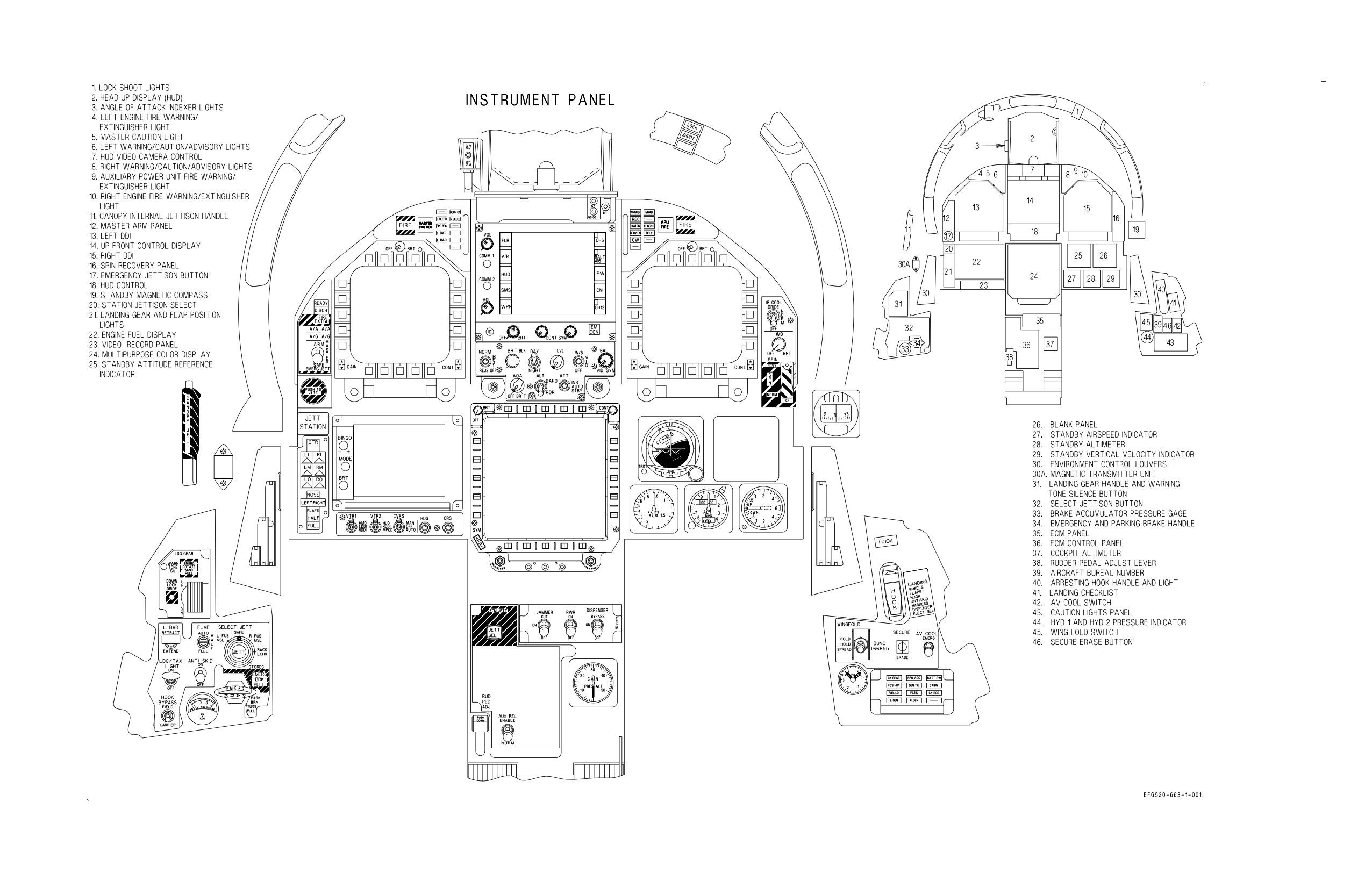
A1-E18GA-NFM-000
Figure FO-1. Forward Cockpit (Sheet 1 of 2)
FO-3 (Reverse Blank)
ORIGINAL
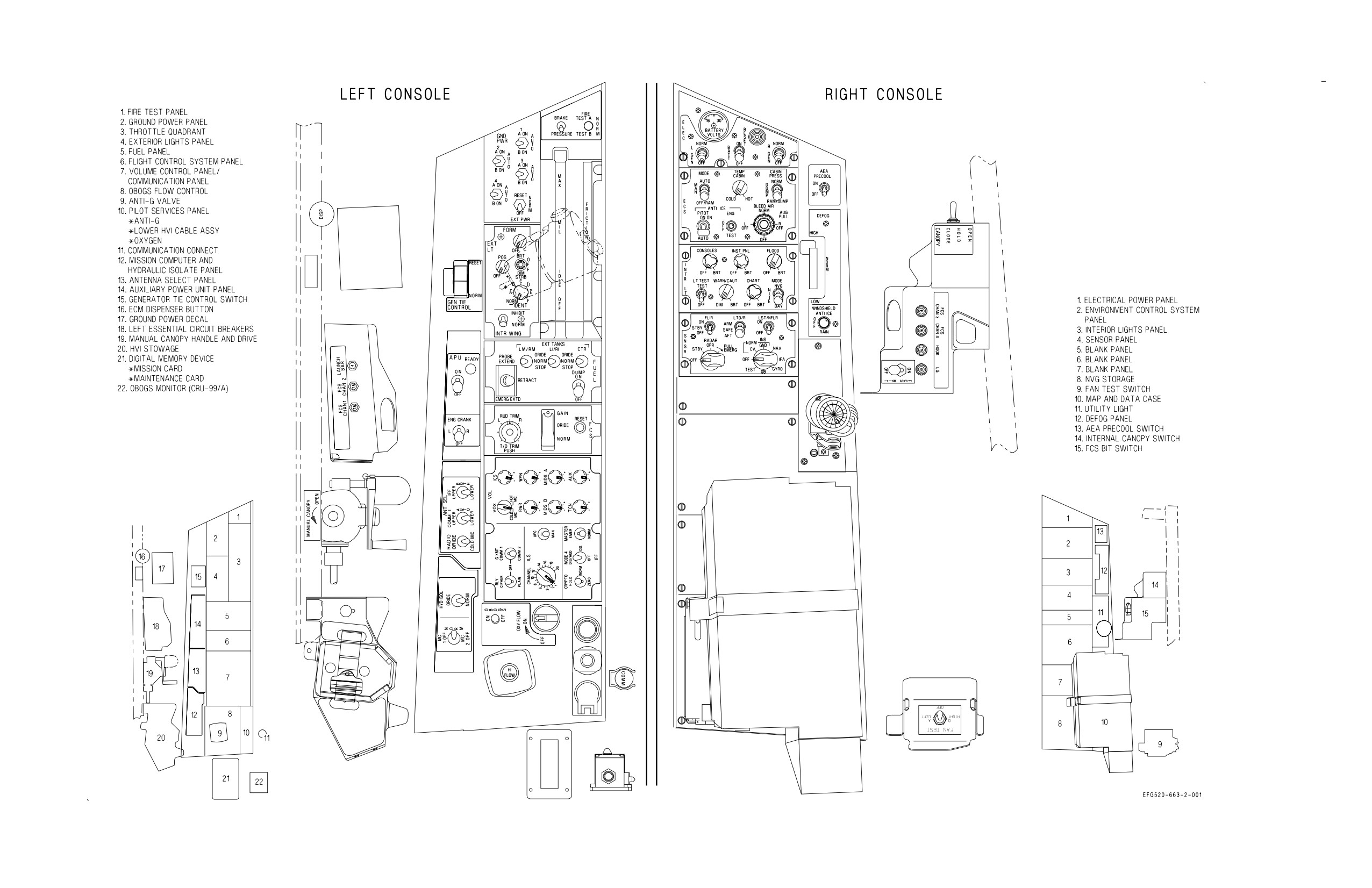
A1-E18GA-NFM-000
Figure FO-1. Forward Cockpit (Sheet 2 of 2)
FO-5 (Reverse Blank)
ORIGINAL
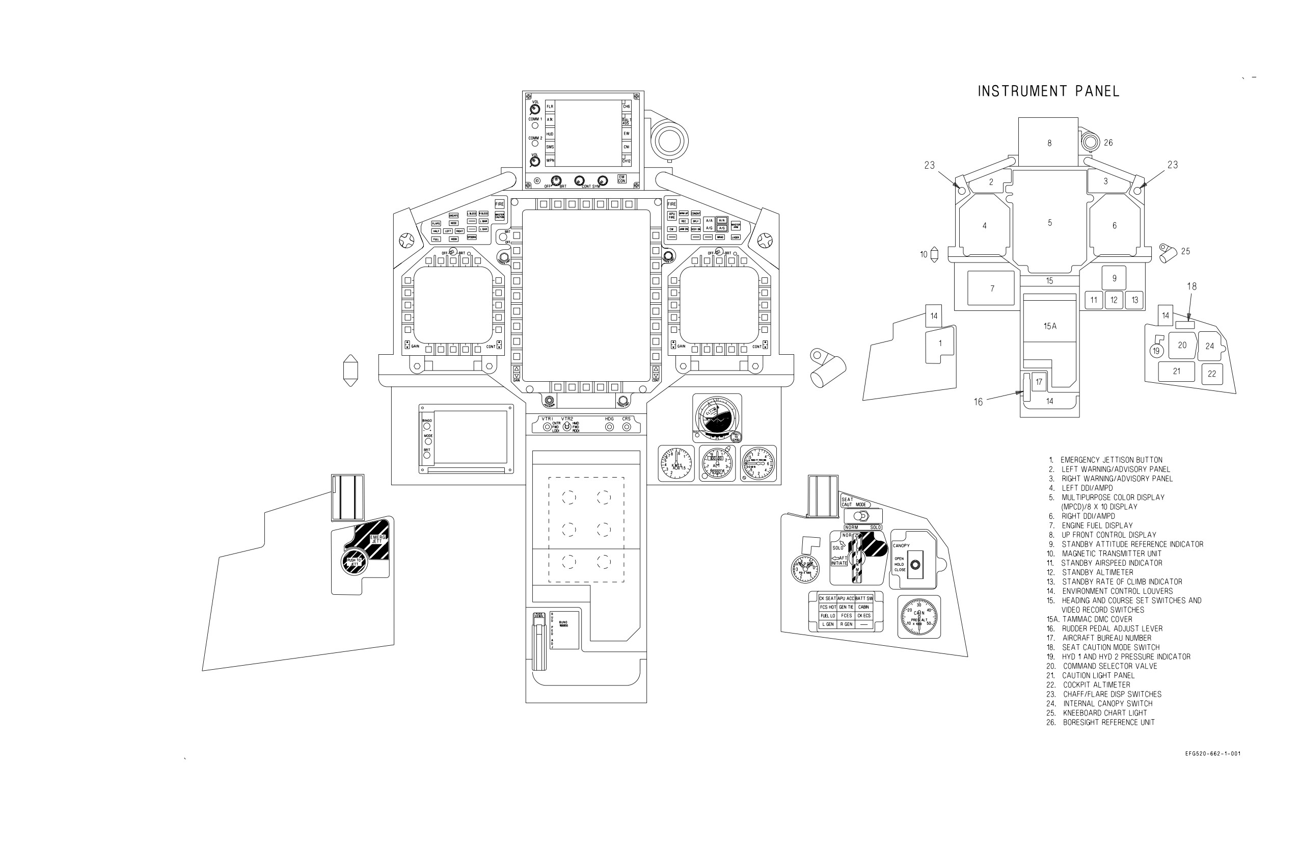
A1-E18GA-NFM-000
Figure FO-2. Rear Cockpit (Sheet 1 of 2)
FO-7 (Reverse Blank)
ORIGINAL
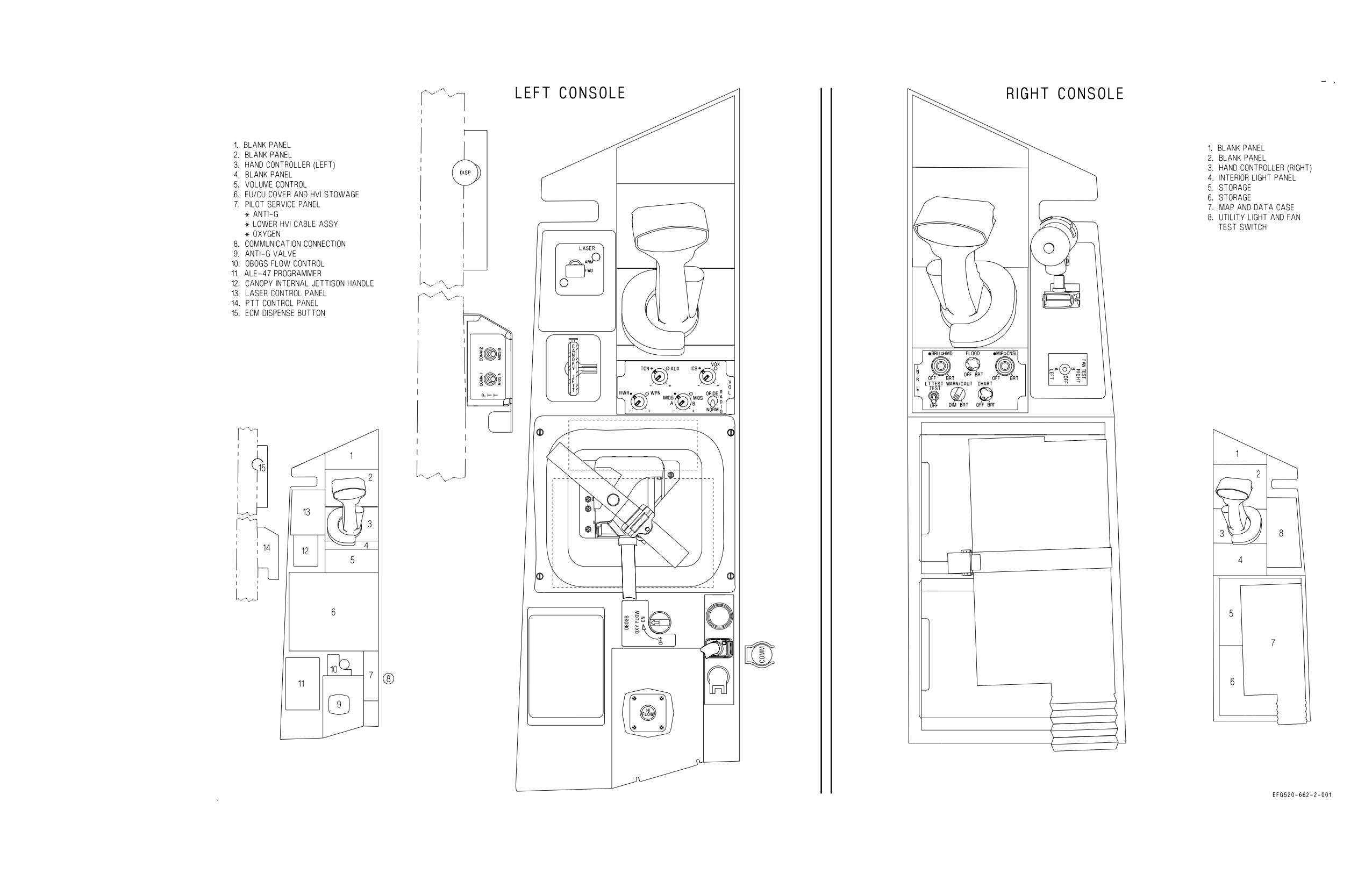
A1-E18GA-NFM-000
Figure FO-2. Rear Cockpit (Sheet 2 of 2)
FO-9 (Reverse Blank)
ORIGINAL
A1-E18GA-NFM-000
ALE-50 CONTROLLER
BATT CHARGER
CSC (AC)
ICE DETECTOR (AC)
R AOA HEATER (AC)
RDDI(s)
TACAN
APPROACH LTS (AC)
BATT HEATER
CVRS (AC)
INTERFERENCE
R ECS DUCT DOOR
RECCE WINDOW DEFOG
TACTS (AC)
RIGHT 115
ARM STA 6 THRU 10
COCKPIT STROBE
GPS
BLANKER
R PITOT HEATER
SMS (AC)
TK 1 XFR PUMP
VOLT AC BUS
ARS POWER
LIGHT
HARM CLC (AC)
JHMCS
R TR
STBY ATTITUDE
26 VAC AUTO XFMR
AVIONICS GROUND
COOLING FAN
HUD (AC)
MC 2
R WINGFOLD EDU
REFERENCE
POSITION LTS
RAD ALT
INDICATORS
RIGHT 26 VOLT
MAGNETIC AZIMUTH DETECTOR (CH 2 & 4)
AC BUS
ALE-47 CONTROLLER
COMM 2
HUD (DC)
ICE DETECTOR (DC)
NVG FLOOD LIGHTS
R PROBE HEATER
SMS (DC)
ALE-47 SEQUENCERS
CSC (DC)
HYD 1 PRESSURE
ICS
R AOA HEATER (DC)
CONTROLLER
TACTS (DC)
RIGHT 28 VOLT
ALE-50 CONTROLLER
CVRS (DC)
INDICATOR
INCANS
R ENG FADEC CH B
R WING UNLOCK
UNDER COOL SENSOR
DC BUS
ALQ-218 (STA 11)
ECS CONTROLLER
HYD 2 PRESSURE
INTERIOR LIGHTS
R PRIMARY BLEED
MOTOR
ARM STA 6 THRU 10
HARM CLC (DC)
INDICATOR
LGCU
AIR SHUTOFF VALVE
SECONDARY BLEED
CBN RAM AIR VALVE
LST/CAM
AIR SHUTOFF VALVE
APU CONTROL
CROSSFEED VALVE
ENG START
FCS AV COOL
FUEL DUMP
R ENG FADEC CH A
SMS
AEA PRECOOL
CROSS COOLING
CONTROL
ACTUATOR
ICS
R ENG OIL PRESSURE
STBY ALTIMETER
ESSENTIAL
BK PRESS IND
VALVE
FCES 1 (EBB)
FEED TK SHUTOFF
IFF EMERG
INDICATOR
STBY ARI (FRONT
28 VOLT
BL AIR LK DET ABL
EMER JETT STAs
FCES 2 (EBB)
VALVE
L ENG FADEC CH A
R FUEL S/O VALVE
COCKPIT ONLY)
AIR LK DET B
(2, 3, 4, 6, 9, 10)
FCES 3 (EBB)
FIRE DET LOOP A
L ENG OIL PRESSURE
R LG PROXIMITY
UTILITY LIGHTS
DC BUS
CABIN EMERG VENT
EMER PROBE EXTEND
FCES 4 (EBB)
FIRE DET LOOP B
INDICATOR
SWITCH
WARNING/CAUTION
VALVE
EFD
FIRE EXTINGUISHER
PITCH TRIM
LIGHTS
COMM 1
AEA PALLET
BCN AUGMENTATOR
EXT FUEL TANK
FUEL TRANSFER
L BLEED AIR CONT
LAUNCH BAR CONTROL
PROBE CONTROL
ALQ-218 (STA 1)
BUS TIE
CONTROL
VALVES
VALVE (PRIM)
VALVE
RADAR (DC)
ALE-47 SEQUENCERS
DATA LINK
EXT LTS CONTROL
GND PWR CONTROL
L ENG FADEC CH B
LG CONTROL VALVES
SEAT ADJ (FRONT &
LEFT 28 VOLT
ALR-67 (DC)
DBFSS
FCCB ASYM BRK DC
HOOK LIGHT
L PROBE HEATER
MATT CONT
REAR)
ANAV
DFIRS POWER
FUEL LOW LEVEL
HOSE JETTISON
CONTROL
MEMORY UNIT (MU)
THROTTLE
DC BUS
ANTI-SKID CONTROL
DIG MAP SET (DC)
WARNING
HYD ISOL ORIDE
L WINGFOLD UNLOCK
MSTR ARM
BACKDRIVE
UNIT
ECM COOLING
ILS (DC)
MOTOR
NWS CONTROL VALVE
WSHLD ANTI-ICE
ANTENNA SELECT
ENG IDL/A-B LKOUT
OBOGS CONTROL
REMOVAL
LEFT 115 VOLT
AEA ECS VLV
EMERG AV COOLING
ILS (AC)
L PITOT HTR
LCS FAN
MATT
PROBE LT
AEA PALLET
FAN
INS
L TR
LCS PUMP
MC 1
RADAR (AC)
AC BUS
ALQ-165 ASPJ
FORMATN LTS
L AOA HTRS (AC)
L WING FOLD EDU
LDDI(s)
MPCD(s)/UFCD(s)
STROBE LTS
ALR-67 (AC)
IFF
L ECS DUCT DOOR
LDG/TAXI LT
OBOGS CONCENTRATOR
ARM STA 2 THRU 5
DIG MAP SET (AC)
MAINTENANCE
APU PRIM
GEN TIE LOGIC
SDC
CANOPY
INS KEEP ALIVE
SMP (CODE CHECK)
BUS
FCS KEEP ALIVE CH 1
LADDER DEPLOY
VENT TANK WET
THRU 4
LIGHT
Figure FO-3. Electrical Bus Power
FO-11 (Reverse Blank)
ORIGINAL
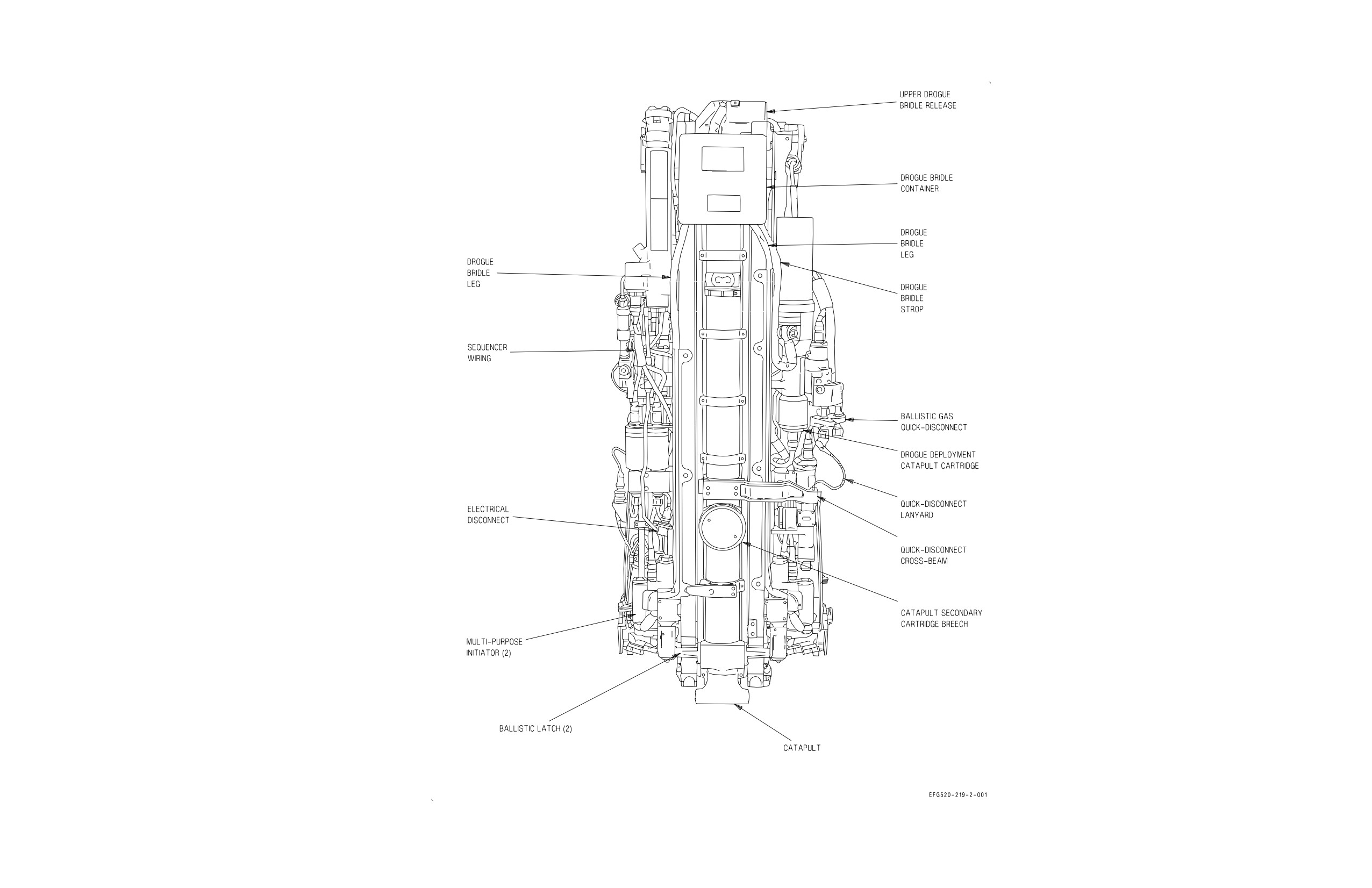
A1-E18GA-NFM-000
Figure FO-4. Ejection Seat (Sheet 1 of 2)
FO-13 (Reverse Blank)
ORIGINAL
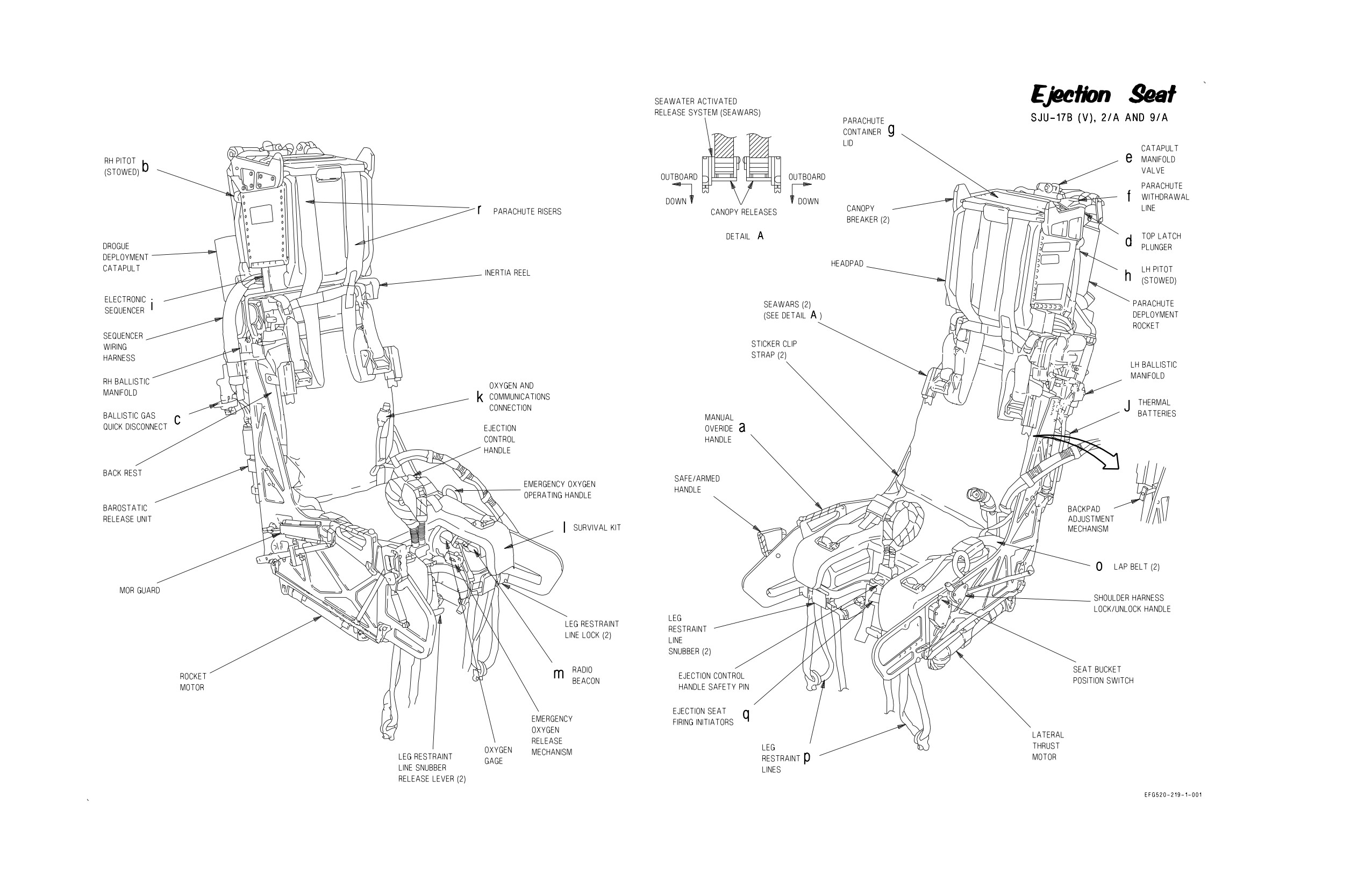
A1-E18GA-NFM-000
Figure FO-4. Ejection Seat (Sheet 2 of 2)
FO-15 (Reverse Blank)
ORIGINAL
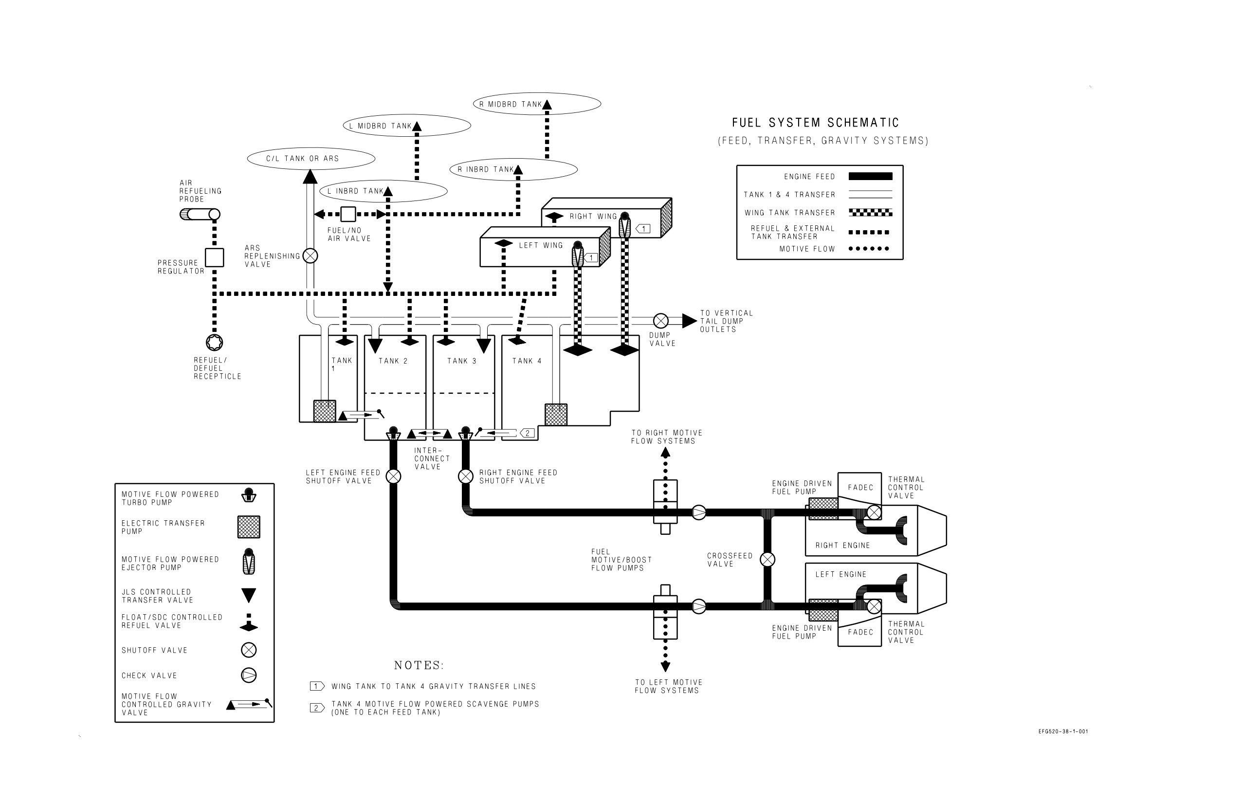
A1-E18GA-NFM-000
Figure FO-5. Fuel System (Sheet 1 of 2)
FO-17 (Reverse Blank)
ORIGINAL
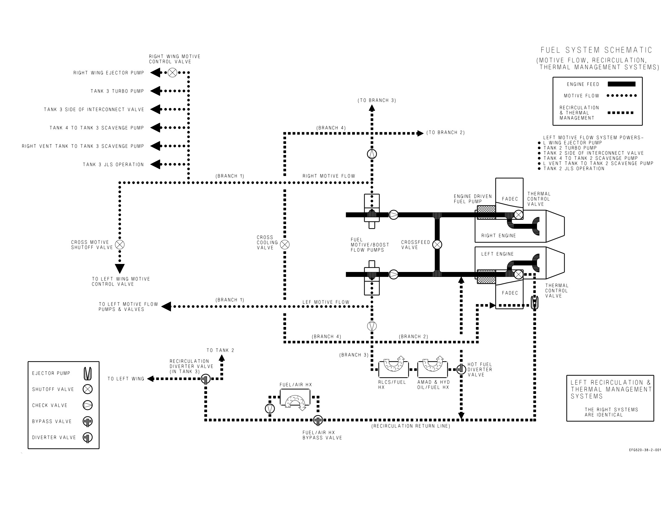
A1-E18GA-NFM-000
Figure FO-5. Fuel System (Sheet 2 of 2)
FO-19 (Reverse Blank)
ORIGINAL
A1-E18GA-NFM-000
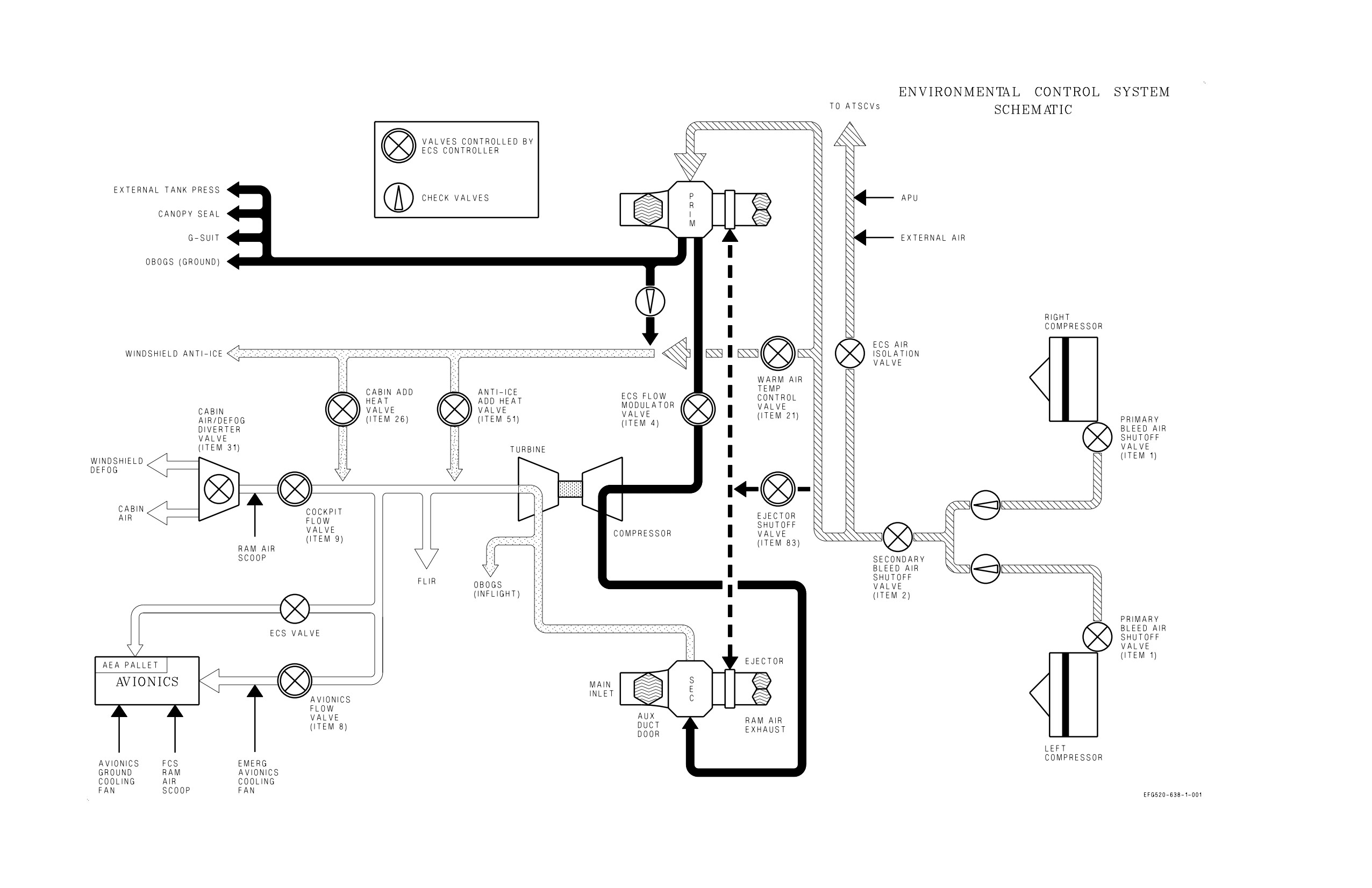
Figure FO-6. Environmental Control System
FO-21 (Reverse Blank)
ORIGINAL
A1-E18GA-NFM-000
ALPHABETICAL INDEX
Page
No.
1
10,000 Feet Checks
III-10-24, III-10-30, III-10-32
10,000 Feet to Landing
III-10-27
10,000 Foot Checks
III-7-34
A
A/A Weapon Select Switch
I-2-88
ABORT
V-14-2, V-18-3
Aborted Takeoff
III-9-1
AC Electrical Power
I-2-30
Acceleration Limitations
I-4-5
ACL Mode 1
VII-24-63
ACL MODE 1 AND 1A APPROACHES
III-8-16
ACL Mode 1A
VII-24-65
ACL Mode 2
VII-24-65
ACL MODE 2 APPROACH
III-8-18
ACL Mode Displays
VII-24-57
ACL Mode Operation
VII-24-60
ACL Option (HSI Format)
VII-24-9
Adaptability/Flexibility
IX-28-1
AEA Pallet Ground Cooling Mode
I-2-95
AEA Power Control
I-2-169
Aerobraking Technique
III-7-41
AFCS Mode Deselection
I-2-86
AFCS Mode Selection
I-2-84
AFCS Related Caution and Advisories
I-2-87
Aft Cooling Fan Shutoff Valve
I-2-97
Aft UFCD MUX FAIL
I-2-171
After Landing
III-7-44
AFTER LANDING
VI-21-2
After Landing Checks
III-7-44, III-10-27
After Takeoff Checks
III-7-34, III-10-21
AFTERBURNER FAILURE
V-15-1
Afterburner Limiting (ABLIM) Function
I-2-5
A/G Weapon Release Button
I-2-90
AHRS Failure Flying Qualities
IV-11-14
AILERON HINGE FAILURE - SUSPECTED, INBOARD
V-15-39
Air Conditioning System (ACS) Pack
I-2-97
Air Data Function
I-2-71
Air Refueling Checklist
III-9-5
AIR REFUELING (RECEIVER)
III-9-5
AIRBORNE CHECKS
III-7-34
Airborne Electronic Attack (AEA) pallet Cooling
I-2-94
Index-1
ORIGINAL
A1-E18GA-NFM-000
Page
No.
Airborne HMD Accuracy Check with Radar
III-9-14
AIRBORNE HMD ACCURACY CHECKS
III-9-13
Aircraft (A/C) Programming
VII-24-31
Aircraft Attitude Data
I-2-215
AIRCRAFT DESCRIPTION
I-1-1
Aircraft Gross Weight
I-1-3
AIRCREW RESPONSIBILITIES BY FLIGHT PHASE
IX-28-3
Airframe Mounted Accessory Drive (AMAD)
I-2-27
Airspeed during Ejection
V-17-2
Airspeed Limitations
I-4-1
AJ MENU From Fixed Frequency COMM Sublevel
VII-23-13
AJ MENU From Have Quick COMM Sublevel
VII-23-20
AJ MENU From SINCGARS COMM Sublevel
VII-23-21
ALE-47 Advisories
I-2-182
ALE-47 Countermeasures Dispensing Set
I-2-182
ALE-47 DISP Switch
I-2-94
Alert Five Launch
III-9-13
ALERT SCRAMBLE LAUNCH PROCEDURES
III-9-12
Alignment Exit
I-2-212
Alignment Verification
I-2-215
All Equipment
I-2-189
ALQ-99 POD FIRE/MECHANICAL MALFUNCTION
V-15-41
ALQ-99 POD RAT FAILURE
V-15-41
ALT Selector Switch
I-2-156
Altitude Required For Recovery Calculations
I-2-137
AMAD Related Cautions
I-2-29
AMPCD
I-2-151, VII-25-2
AMPCD Initiated BIT
I-2-195
ANAV BIT
VII-24-20
Angle Of Attack Indexer
I-2-141
ANTI SKID Switch
I-2-53
Anti-g System
I-2-104
Anti-Jam Operation
VII-23-13
Anti-skid BIT and the ANTISKID Caution
I-2-53
Anti-skid System
I-2-51
AOA Indexer Control Knob
I-2-156
AOA Limit Display
I-4-5
AOA Limitations - Flaps AUTO
I-4-5
AOA Probes
I-2-72
AOA Warning Tone
I-2-75
Applicable Publications
X-30-4
Approach
III-9-6, III-9-11
Approach
IX-29-5
Approach Lights
I-2-39
Approaches
VI-19-1
Approach/Landing (*)
X-30-4
APU Fire Extinguishing System
I-2-112
APU FIRE Light
I-2-111
Index-2
ORIGINAL
A1-E18GA-NFM-000
Page
No.
APU FIRE LIGHT
V-18-1
APU READY Light
I-2-28
APU Switch
I-2-28
ARC-210/DCS
VII-23-28
Area
X-30-2
Areas of Limited CFIT Protection
I-2-139
Areas of No CFIT Protection
I-2-140
Armament Gas Ingestion (AGI) Protection
I-2-4
Arrested Landing
III-9-11
ARRESTED LANDING AND EXIT FROM THE LANDING AREA
III-8-20
Arresting Gear Types
V-16-13
Arresting Hook System
I-2-57
ARRESTMENT - FIELD
V-16-13
Arrestment - Long Field
V-16-14
Arrestment - Short Field
V-16-14
Arrestment and Exit From the Landing Area
III-8-23
Arrestment Decision
V-16-14
Assertiveness
IX-28-1
Asymmetric Stores Landings
III-7-43
ATC Approach Mode Technique
III-8-14
ATC Approaches
III-7-39
ATC Automatic Disengagement
I-2-11
ATC Disengagement
I-2-11
ATC Engagement
I-2-10
ATC Related Cautions
I-2-11
ATS Air Sources
I-2-28
ATS Protection
I-2-29
ATT Selector Switch
I-2-157
AUG PULL
I-2-29, I-2-101
AUTO BIT
I-2-192
AUTO Option (HSI Format)
VII-24-8
AUTO Sequential Steering
VII-24-40
AUTO Update
VII-24-35
Automatic Battery Cutoff
I-2-33
Automatic Carrier Landing (ACL) Mode
VII-24-56
Automatic Erase
I-2-145
AUTOMATIC FLIGHT CONTROL SYSTEM (AFCS)
I-2-84
Automatic Throttle Control (ATC)
I-2-10
Auxiliary Power Unit (APU)
I-2-28
AV COOL Switch
I-2-62, I-2-104
Avionics BIT
I-2-183
Avionics Cooling Fans
I-2-97
AVIONICS SUBSYSTEM
I-2-141
B
Backpad Adjustment Mechanism
I-2-125
BACKUP ATTITUDE AND NAVIGATION SYSTEM
VII-25-1
Backup Attitude and Navigation System Controls and Indicators
VII-25-2
Index-3
ORIGINAL
A1-E18GA-NFM-000
Page
No.
Backup Erase Controller
I-2-146
BACKUP FREQUENCY CONTROL
VII-25-5
Backup Heading Mode Control
VII-25-4
Backup Navigational Information on Backup HUD
VII-25-1
BAL Control Knob
I-2-156
Balanced Cruise Formation
III-9-4
Barometric Altitude Hold (BALT)
I-2-86
Barometric (BARO)/Radar Low Altitude Warning Programming
VII-24-32
BARRICADE ARRESTMENT
V-16-14
Basic Autopilot
I-2-86
BATT SW Caution and Caution Light
I-2-33
BATT Switch
I-2-33
Battery
I-2-32
Battery Gauge
I-2-33
Before Engine Shutdown Checks
III-7-46, III-10-28
Before Entering Cockpit
III-7-9
BEFORE ENTERING COCKPIT
VI-22-1
Before Takeoff
VI-19-1
Before Takeoff Checks
III-7-29
Before Taxi
III-8-21
BEFORE TAXI
VI-22-1
BEFORE TAXI CHECKS
III-7-22
Before Taxi Checks
III-8-2, III-10-15, III-10-31
BIT Initiation
I-2-186
BIT Recording On The Memory Unit
I-2-208
BIT Top Level Display
VII-23-33
BIT-STATUS MONITORING SUBSYSTEM
I-2-182
Black Level Control Knob
I-2-156
BLEED AIR Knob
I-2-95
Bleed Air Leak Detection (BALD) System
I-2-113
Bleed Air Leak Detection System Test
I-2-113
Bleed Air Shutoff Valves
I-2-95
Bleed Air Subsystem
I-2-96
BLIN Codes
I-2-197
BLOCK NUMBERS
I-1-3
Boarding Ladder
I-2-117
Bolter
III-9-11
Boresight Reference Unit (BRU)
I-2-203
Brake Accumulator Pressure Gauge
I-2-45
BRAKE FAILURE/EMERGENCY BRAKES
V-13-3
Braking Technique
III-7-40
Breathing Regulator
I-2-109
Briefing
III-6-1
BRIEFING/DEBRIEFING
III-6-1
Brightness and Contrast Controls
I-2-150
Brightness Knob
I-2-147
BRK PRESS Switch
I-2-46
Built-In Test (BIT)
I-2-204
Index-4
ORIGINAL
A1-E18GA-NFM-000
Page
No.
C
CABIN Caution Light
I-2-103
Cabin Louvers/Foot Air Outlet
I-2-101
CABIN PRESS Switch
I-2-103
Cabin Pressure Altimeter
I-2-103
Cabin Pressurization
I-2-102
Cabin Pressurization Warning System (CPWS)
I-2-103
CABIN TEMP knob
I-2-101
Cage/Uncage Button
I-2-90
CANOPY JETT Handle (Front Cockpit)
I-2-117
CANOPY JETT Handle (Rear Cockpit)
I-2-117
Canopy Jettison System
I-2-117
Canopy Operation
I-2-115
Canopy Switch (External)
I-2-115
CANOPY Switch (Internal)
I-2-115
Canopy System
I-2-114
CAS Operating Modes
I-2-63
Catapult Endspeed Requirements
III-8-11
Catapult Hook-Up
III-8-9, III-8-21
Catapult Launch
III-8-10, III-8-21
Catapult Launch Flyaway Characteristics
III-8-12
Catapult Suspend
III-8-11, III-8-23
Catapult Trim
III-8-4
Cautions and Advisories
I-2-186, VII-23-33
Cautions/Advisories
I-2-203
Ceiling/Visibility Requirements
II-5-3
CFIT Protection Provided
I-2-137
CG Limitations
I-4-1
Chaff/Flare Dispense Switch
I-2-92
Chaff/Flare/ALE-50 Dispense Switch
I-2-90
CHART Light Knob
I-2-41
Ciphered Reception
VII-23-24
Ciphered Relay Mode
VII-23-24
Ciphered Transmission
VII-23-24
Circuit Breakers
I-2-36
CK ECS Caution Light
I-2-103
CK SEAT Caution
I-2-121, I-2-126
Climb
III-7-34
Climb/Cruise
X-30-4
Closed Book Examination
X-30-2, X-30-3
Coarse Alignment
I-2-209
Cockpit AEA Precool switch
I-2-94
Cockpit Controls and Displays
I-2-146
Cockpit Displays Initiated BIT
I-2-192
COCKPIT SMOKE, FUMES, OR FIRE
V-15-14, V-18-4
COCKPIT TEMPERATURE HIGH
V-15-13
Cockpit Unit (CU)
I-2-203
Cockpit Video Recording System (CVRS)
I-2-173
Index-5
ORIGINAL
A1-E18GA-NFM-000
Page
No.
COMM 1 and 2 Channel Knobs
I-2-172
COMM 1 AND 2 OPERATION
VII-23-8
COMM 1 and 2 VOL (Volume) Control Knobs
VII-23-4
COMM 1 and COMM 2 Channel Select Knobs
VII-23-4
COMM 1 and COMM 2 Volume Controls
VII-23-28
COMM 1 Antenna Select (ANT SEL) Switch
VII-23-7
COMM BIT Sub-Level Display
VII-23-33
COMM Control Panel
VII-23-6
COMM Foot Pedal Switches
VII-23-7
COMM Keypad Options and Scratchpad Display
VII-23-5
COMM Sublevel - Guard and Cue Presets
VII-23-9
COMM Sublevel - Manual Preset
VII-23-10
COMM Sublevel - Presets 1 Thru 20 (Anti-Jam)
VII-23-18
COMM Sublevel - Presets 1 Thru 20 (Fixed Frequency)
VII-23-12
COMM Sublevel - Ship Maritime Preset
VII-23-9
COMM Sublevel Selection
VII-23-8
COMM Throttle Switch
VII-23-7
COMM Touch Option/Displays
VII-23-5
COMM VOL Knobs
I-2-172
Communication
IX-28-1
COMMUNICATION-IDENTIFICATION DATA ENTRY
VII-23-47
COMMUNICATION-NAVIGATION-IDENTIFICATION INTERFACE
VII-23-47
COMMUNICATIONS
IX-29-1
Communications
X-30-4
CONCEPT
X-30-1
Conditionally Qualified
X-30-1
CONFIG Display
I-2-198
CONFIG Display Country ID Code
I-2-197
Configuration Check
I-2-204
CONSOLES Lighting Knob
I-2-41
CONT Control
I-2-147
Contact
III-9-7
Control Augmentation System (CAS)
I-2-64
CONTROLLABILITY CHECK
V-15-19
Countdown Time (CD)
VII-24-32
COUNTERMEASURES DISPENSING SYSTEM
I-2-182
Coupled Auto Sequential Steering
VII-24-41
Coupled Data Link Modes
I-2-87
Coupled Steering Modes (CPL)
I-2-87
Coupled TACAN Steering
VII-24-50
Coupled Waypoint/OAP Steering
VII-24-40
CREW BRIEFING
IX-29-1
Critical Area/Sub-area
X-30-2
CRITICAL SKILLS OF AIRCREW COORDINATION
IX-28-1
Critique
X-30-5
Crossfeed Valve
I-2-12
Crosswind Landings
III-7-42
Crosswind Takeoff
III-7-33
Index-6
ORIGINAL
A1-E18GA-NFM-000
Page
No.
CRS Select Switch
VII-24-9
CRS Set Switch
I-2-147, I-2-166
Cruise
III-7-34
Cruise
IX-29-4
Cruise Check
III-7-35
Crypto Key Options
VII-23-28
CRYPTO Switch
VII-23-46
CURRENCY REQUIREMENTS
II-5-2
CV Alignment Modes
VII-24-12
CV Manual Alignment
VII-24-13
CV RECOVERY MATRIX
V-16-15
CV RF/CBL (SINS) Alignment
VII-24-13
CVRS Control Switches
I-2-174
CVRS Mode Switch
I-2-174
CVRS RDCR ON Light
I-2-174
D
Data Entry
VII-23-47
Data Entry Using the Alphanumeric Keypad
I-2-167
Data Entry Using the Keypad
I-2-167
Data Entry Using the Shifted Keypad
I-2-167, VII-23-47
DATA LINK SYSTEM
VII-24-54
DATA Option (HSI Format)
VII-24-7
Date (DATE)
VII-24-33
Day ID Light
I-2-40
Day ID Test Switch
I-2-40
DAY OPERATIONS
III-8-1
DC Electrical Power
I-2-32
DCS - Avionics Subsystem
VII-23-31
DCS Communications Security (COMSEC)
VII-23-28
DDI Controls
VII-23-28
DDI Formats on MPCD
I-2-151
DDI Pushbuttons
I-2-147
DDI/HUD Initiated BIT
I-2-192
DDIs
I-2-147
Debriefing
III-6-4
DEBRIEFING
IX-29-7
Decision-Making
IX-28-1
DEFENSIVE COMBAT MANEUVERING
IV-11-5
DEFINITION
IX-28-1
Definitions
X-30-1
DEFOG Handle
I-2-102
DEGRADED MODE HANDLING QUALITIES
IV-11-8
DEGRADED SYSTEMS
VI-19-1
Departure
IX-29-3
Departure Characteristics
IV-11-6
Departure from Controlled Flight
V-15-17
Departure Recovery
V-15-17
Index-7
ORIGINAL
A1-E18GA-NFM-000
Page
No.
Departure Resistance
IV-11-6
Departures with Lateral Weight Asymmetries
V-15-17
Deployable Flight Incident Recorder Set (DFIRS)
I-2-182
Descent
VI-19-1
Descent/Penetration
III-7-35
Descent/Penetration Checks
III-7-35
DESCENT/RECOVERY
VI-21-2
Design Limit-g
I-2-68
Designation
VII-24-42
Designation (DSG) Update
VII-24-34
Designator Controller (DC)
I-2-92
Designator Controller (DC) Assignment Switch
I-2-92
DFIRS Record Code 8
I-2-136
DIGITAL COMMUNICATION SYSTEM (DCS)
VII-23-27
Dimming and Test Functions
I-2-128
Disengagement
III-9-7
DISPENSER Switch
I-2-182
DISPLAY MALFUNCTION
V-15-16
DITCHING
V-17-4
D/L Option (HSI Format)
VII-24-9
DMD Maintenance Format Options and Display Information
I-2-178
DMD/PC Cards Cautions and Advisories
I-2-181
DOUBLE TRANSFORMER-RECTIFIER FAILURE
V-15-8
DOWNLOCK ORIDE Button
I-2-47
Dry Bay Fire Suppression System (DBFS)
I-2-114
DUAL L BLEED and R BLEED WARNING LIGHTS//L/R ATS CAUTION
V-18-1
DUAL MISSION COMPUTER (MC) FAILURE
V-15-16
E
EAU Power Control
I-2-171
ECS AUTO Mode
I-2-98
ECS Auxiliary Duct Doors
I-2-96
ECS MAN Mode
I-2-99
ECS MODE Switch
I-2-101
ECS OFF/RAM Mode
I-2-100
ECS Operating Modes
I-2-98
ECS Related Warnings, Cautions, and Advisories
I-2-106
ECS RESET
I-2-104
ECS RESET and AV COOL Switch
I-2-104
EFD Initiated BIT
I-2-195
Effects of Light
III-9-10
Effects on Vision
III-9-9
EJECT MODE Handle
I-2-125
EJECTION
V-17-1
Ejection Control Handle
I-2-120
Ejection Procedures
V-17-4
Ejection Seat
I-2-119
Ejection Seat Restrictions
V-17-1
Index-8
ORIGINAL