HELICOPTER, ATTACK, AH-64D LONGBOW APACHE. TECHNICAL MANUAL (2002) - page 12
TM 1-1520-251-10
set-up and shut-down of loading operations. Their use re-
pylon and the ballistic ejector for stores jettison. The PIU
quires that the MODE Switch be placed in the AUTO posi-
provides the interface between the weapons processor
tion and the OPERATE Switch be placed in the OFF posi-
and pylon discrete signals. The pylons can be articulated
tion.
in elevation by hydraulic power in response to pointing
commands from the weapons processor. The pylons are
d. MODE Switching. This three position latching
equipped with hydraulic and electrical quick-disconnect
toggle switch provides three command modes. Center
provisions and contain electrical aircraft interfaces for the
position is OFF, prohibiting any S/MC loading operations.
2.75 in. Aerial Rocket Subsystem, auxiliary fuel tanks,
The down position is used for MANUAL operations which
Hellfire Modular Missile System and servo control of rack
is used only as needed by the operator to address non-
position.
standard operating conditions. The up position is the AU-
4.69.2 Wing Stores Jettison. Each pylon is equipped
TO mode for which Sideloader system use is optimized. In
with an electrically operated ballistic ejector circuit to jetti-
the AUTO mode, the operator is freed from control inputs
son the attached wing store. Refer to Chapter 2, para-
while uploading of ammunition is accomplished. Down-
graph 2.28 for operation.
loading in all operating modes requires the operator to
maintain pressure on the OPERATE toggle switch, in the
4.70 WING STORES PYLON SUBSYSTEM
downward direction, to accomplish the DOWNLOAD op-
OPERATION
eration.
The weapons processor commands the pylons to the re-
e. OPERATE Switching. This three position toggle
quired elevation angles for the various fire control modes.
switch provides three operational states. Center position
The modes include ground stow, flight stow, and articula-
is OFF, prohibiting all Loader Assembly operations except
tion mode.
AUTO ENGAGE and DISENGAGE. The DOWNLOAD
position operates the Sideloader system in the download
4.70.1
Ground Stow. The ground stow mode com-
direction as long as the operator maintains pressure on
mands the pylons to a stow position ( - 5°) so that the wing
the toggle switch. The toggle switch latches in the up
stores are parallel with the ground (level terrain). The
(UPLOAD) position only during AUTO MODE operation.
ground stow mode is automatically commanded when the
While in the MANUAL MODE, operator pressure must be
squat switch indicates GROUND and either a rocket
maintained in either the UPLOAD or DOWNLOAD posi-
launcher or a hellfire launcher is present. The pylons can
tion for continued operation.
be manually ground stowed while in flight using the WPN
UTIL page.
4.68.2 Turret Control Box. The TCB serves as the gun
turret assembly controller performing BIT, mode control,
4.70.2 Flight Mode. The flight mode commands the py-
and turret servo loop closure in response to commands
lons to a single fixed position (+4°). The flight mode is au-
received from the Weapons Processors. The TCB pro-
tomatically commanded ON at takeoff when the squat
vides intermediate power outputs to the Gun Control Box
switch indicates airborne for more than 5 seconds.
(GCB) as well as the Train Rate Sensor (TRS) and eleva-
4.70.3 Articulation. In flight the pylons remain in the
tion actuator located in the gun turret assembly. The TCB
flight mode until missiles or rockets are actioned. Pylons
outputs arming and firing signals to the GCB to control
are independently controlled through a range of +4° to
gun firing. The TCB also processes bolt position status
- 15° in elevation.
from the GCB to derive rounds decrement status which is
output to the Weapons Processors.
4.71 AERIAL ROCKET SUBSYSTEM DESCRIPTION
4.69 WING STORES PYLON SUBSYSTEM
The 2.75 in. Aerial Rocket Subsystem consists of light-
DESCRIPTION
weight rocket launchers mounted on any of the four wing
stations. Remote fuzing capability is incorporated and ac-
The Wing Stores Pylon Subsystem consists of four pylon
commodates use of both penetration and air burst fuze
assemblies, a Selectable Stores Jettison panel, and an
types. Penetration fuzes permit use of variable detonation
Emergency Jettison button.
timing to defeat bunkers and targets masked by forest
canopy. Air burst fuzes permit deployment of payloads at
4.69.1 Wing Store Pylons. The wing store pylon con-
optimum range and height offsets.
sists of a pylon frame, the ejector rack, Pylon Interface
Unit (PIU), pylon actuator, and pylon fairings. The ejector
4.71.1 Rocket Launcher. The M261 lightweight rocket
rack contains attaching lugs for securing the store to the
launcher consists of 19 tubes in a cylindrical configuration
Use or disclosure of this information is subject to the restriction(s) on the title page of this document.
4-95
TM 1-1520-251-10
and a hardback with 14 inch lug spacing. Each tube con-
struction may be reduced to 350 ft. Fir-
tains a mechanical detent for holding the rocket until fired.
ing this combination with the
Two electrical interface connectors are provided: one for
ballistics for the M151 warhead will re-
providing firing signals to the rocket motor igniters and the
sult in reduced rocket range.
other for externally setting the rockets fuze circuitry.
• Firing MK66 in a hover or low speed at
4.71.2
2.75 Inch Folding Fin Aerial Rockets. The
a height of less than 7 ft AGL, and for
rocket system is compatible with the MK-66 rocket type.
all other flight conditions of 5 ft AGL,
Available warhead and rocket motor types are listed be-
is not authorized.
low:
• Do not fire rockets with the M433 fuse
MK-66 Rocket Motor/Warheads
in situations where they might fly
closer than 51m from other airborne
• 6PD
- Point Detonation, High Explosive
helicopters. This restriction comes
• 6RC
- Penetration, High Explosive
from Safety of Usage Message, U. S.
• 6MP
- Time, Multi-purpose Submunition
Army Industrial Operations Command
(SOUM IOC) #2-97.
• 6IL
- Time, Illumination
• 6SK
- Time, Smoke
• Due to the possibility of surging the
• 6FL
- Flechette
engines, do not fire rockets from in -
board stations. Fire no more than
4.72
AERIAL ROCKET SUBSYSTEM OPERATION
pairs with two outboard launchers ev-
ery three seconds, or fire with only
one outboard launcher installed with-
CAUTION
out restrictions (ripples permitted).
These are the only conditions per-
Firing of 2.75 inch Hydra-70 rocket con-
mitted.
figuration (fuse/warhead/motor) flight
conditions as follows:
• Use of the MK66 MOD 2 rocket motor
NOTE
is prohibited.
• Re - inventory and attempting to fire 6MP,
• Rockets with jericho nozzles are pro-
6FL, and 6SK rocket types, after a NO -
hibited.
FIRE event is not recommended due to
significant impact on accuracy. The rock-
• Do not use a MK66 rocket motor which
ets should not be used for at least 10
has been continuously stored above
days to allow the M439 fuse to reset.
140° F (60° C).
• Discard any rocket which has been
• The minimum range to target when firing
dropped.
Flechette rocket is 800 meters. The effec-
tive range with MK66 rocket motors is 1
• M439/M261/MK66 at ranges less than
to 3 Km. Effectiveness is reduced with
1000 meters and/or speeds greater
ranges greater than 3 Km.
than 90 kts are not authorized.
• When forward airspeed exceeds 10
KTAS, do not use M229/M423 war-
The Aerial Rocket Subsystem can be employed indepen-
head/fuse combination for engage-
dently by either crewmember or in the cooperative mode
ment of targets under 450 ft distance,
when the active sight is HMD, TADS, or FCR
. The sub-
and ensure the line of fire is clear of
system permits the crewmember to select the warhead
obstruction (trees/buildings) for at
and quantity desired. Articulating wing pylons move in
least 450 ft. When at a hover or for-
elevation based on the selected sight and weapons pro-
ward airspeed is less than 10 KTAS,
cessor ballistics calculations, while the crewmember
engagement distance and the require-
aligns helicopter heading based on steering symbols pro-
ment for line of fire to be clear of ob-
vided on cockpit displays.
Use or disclosure of this information is subject to the restriction(s) on the title page of this document.
4-96
Change 4
TM 1-1520-251-10
4.73 LONGBOW HELLFIRE MODULAR MISSILE
4.74.4 RF Missile Transfer Alignment. Transfer align-
SYSTEM DESCRIPTION
ment (transfer of aircraft inertial data to missile inertial
platform) occurs automatically, whether in - flight or not, at
missile powerup with no pilot action required. The “R” in
The Longbow Hellfire Modular Missile System is the pri-
the missile icon on the WPN page indicates that the mis-
mary weapon on the AH-64D. The system consists of mis-
sile is ready to receive the target.
sile launchers mounted on any of the four wing pylons.
The system employs SAL 1 and SAL 2 and RF Hellfire
4.74.5 RF Missile Target Handover. The missile re-
missiles. The SAL portion of the missile system is capable
ceives targeting information, to include North, East, and
of both PRF and PIM laser code operation.
Down data, from the acquisition source:
4.73.1 Missile Launcher. The M299 missile launcher
• TADS
consists of a hardback, a removable Launcher Electronics
Assembly (LEA), and four missile rails. The launcher is
• FCR
capable of firing all Hellfire missile types.
•
IDM
4.73.2 Hellfire Missile. The missile is comprised of
four major assemblies; the guidance section, the warhead
Handover will occur when the WAS is actioned during a
group, the control section, and the propulsion section.
scan or if WAS is actioned prior to a scan, handover will
Currently the missile system employs two types of SAL
occur after the first scanburst of the scan is completed.
missiles:
• Basic (SAL 1)
4.74.6
RF Missiles Launch. RF missiles may be
• Hellfire II (SAL 2)
launched after target acquisition using targeting data from
the FCR
or the aircraft’s fire control system, TADS, and
targeting data received through the IDM. Automatic mis-
The SAL 1 missile is capable of only PRF laser codes.
sile firing selection from alternating sides of the aircraft is
SAL 2 missiles are capable of both PRF and PIM laser
performed by the WP to minimize the possibility of missile
codes.
radars from interfering with each other. Targets will be as-
signed by the WP to missiles on opposite sides of the air-
4.74 LONGBOW HELLFIRE MODULAR MISSILE
craft, with only one missile per side possessing a target at
SYSTEM OPERATION
any given time. If missiles are only present on one side,
only one missile will be assigned a target.
4.74.1 Target Designation Modes. Laser target desig-
nation may be autonomous or remote. Autonomous is
NOTE
when the target is designated by the aircraft. Remote is
when the target is designated by a remote laser source.
Operation of tactical missiles is not possible
while the training mode is enabled. All tacti-
4.74.2 Missile Launch Types. The aircrew has the ca-
cal missile icons will be coded as NA on the
pability of two types of missile launches; Lock-On-Before
WPN page.
Launch (LOBL) where the missile is tracking prior to
launch, and Lock-On-After Launch (LOAL) where the
4.74.7 TRAIN Mode. The TRAIN mode enacts a soft-
missile acquires and tracks the target after launch.
ware component (Training Mission Emulator [TME])
loaded in the missile launcher that provides the capability
4.74.3 RF Missile Loading. Loading of RF missiles
of simulating missile operations. The TME can simulate
should be balanced between both sides of the aircraft, pri-
the functioning of 4 RF missiles for each launcher. The
marily on outboard launchers. This allows automatic mis-
TME emulates the missile control decision making pro-
sile firing selection from alternating sides of the aircraft to
cess, replicates the missile launch mode selection pro-
minimize the possibility of missile radars from interfering
cessing, target acquisition and tracking function, BIT rou-
with each other. Outboard launcher loading also mini-
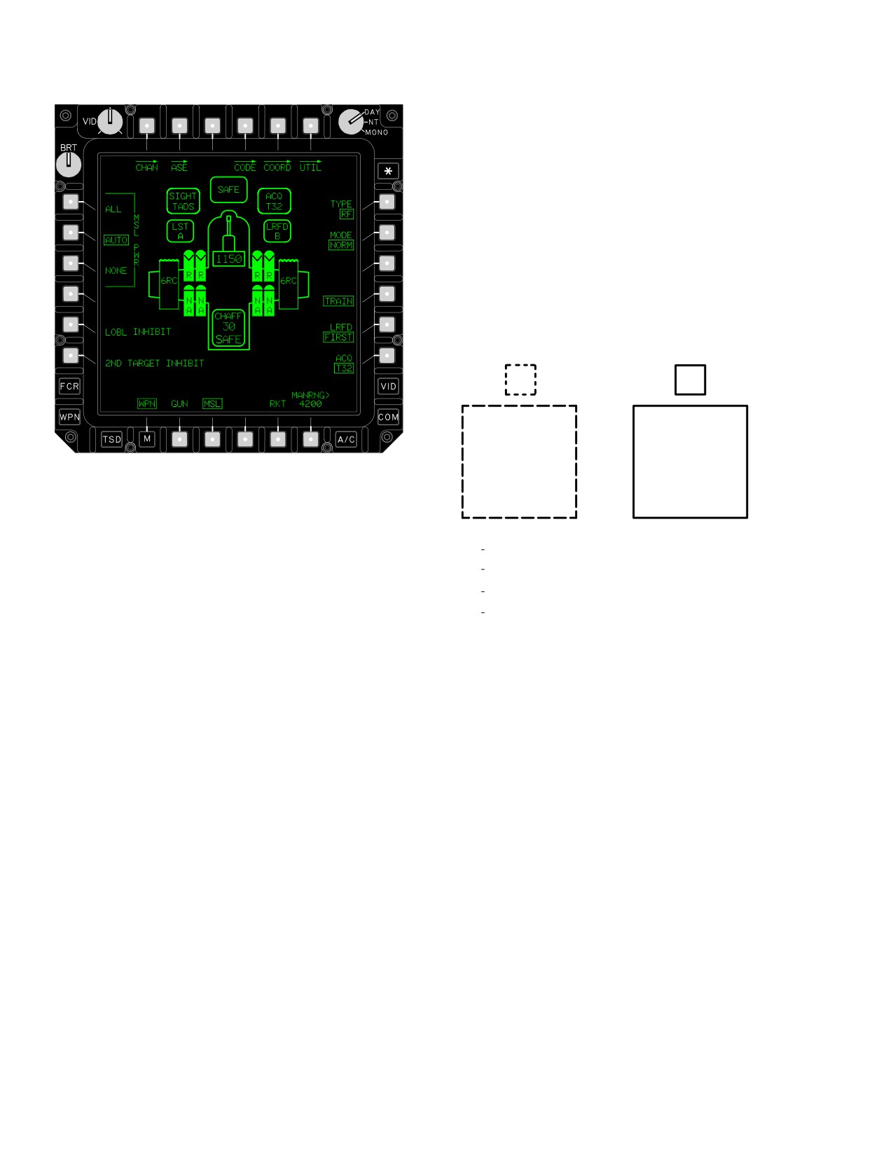
tines and thermal management characteristics (fig 4-92).
mizes missile-to-target masking by the aircraft fuselage
During simulated Hellfire missile launch, rocket launch, or
by selecting missiles from alternating sides. Missile-to-tar-
if gun fire occurs, the Communications Interface Unit will
get masking by the fuselage increases crew workload
provide the respective weapons launch/firing audio effect.
associated with keeping missiles within launch
for additional TRAIN mode functionality, refer to para-
constraints.
graph 4.76.
Use or disclosure of this information is subject to the restriction(s) on the title page of this document.
Change 2
4-97
TM 1-1520-251-10
(3) Upon actioning the missile system, the TME
transitions to the prelaunch mode and target assignments
from the FCR are passed to the firing missile. In the pre-
launch mode the TME will replicate target acquisition and
tracking characteristics.
(4) HAD Messages and WPN page icons will be
displayed in conjunction with the TME track processing.
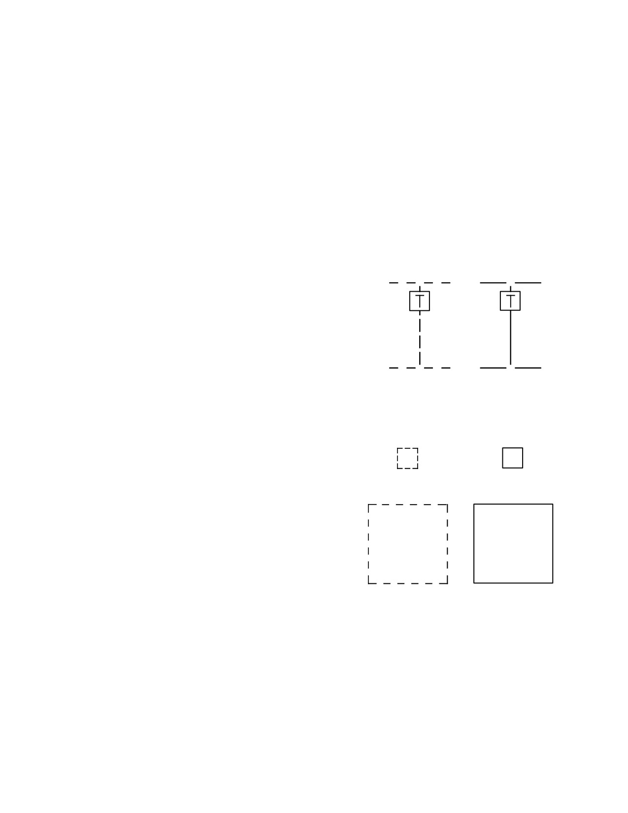
(5) A centered “T” (fig 4-93) will be displayed in the
missile constraints box when the training mode is enabled
and the weapon system is actioned.
1
2
T
T
LBA2555
T
T
Figure 4-92. WPN Page with TRAIN ON
3
4
1 LOAL OUT−OF−CONSTRAINTS MISSILE BOX
a. Training Mode BIT Functions. The training
2 LOAL IN−CONSTRAINTS MISSILE BOX
mode will replicate PBIT and IBIT functions with appropri-
ate delays built in for simulation accuracy. IBIT may be ini-
3 LOBL OUT−OF−CONSTRAINTS MISSILE BOX
tiated when the system has completed PBIT and is not ac-
4 LOBL IN−CONSTRAINTS MISSILE BOX
tioned. IBIT can be commanded on an aircraft power up,
LBA2585
but will not function until PBIT is complete.
Figure 4-93. Missile Constraints Boxes
b. Thermal Management. A training mode missile
(Training Mode)
is allowed an elapsed ON time of 30 minutes. If this time is
exceeded, an overtemperature (OT) symbol will appear
on the affected missile icon on the WPN page. The timer
(6) The weapon inhibit field will display “SAFE”
can be reset by turning the missile OFF and then back
when the training mode and missile system is actioned
ON.
and the weapon system is safed. Upon arming the weap-
on system, the weapon inhibit field will change to “TRAIN-
c. TME Operational Sequence.
ING”.
NOTE
(7) Upon determining that the firing missile has
met all prelaunch constraints, it will notify the WP, which
The TRAIN button is not displayed until mis-
will display the “in constraints” box on the weapons
sile power is applied.
symbology display. The trigger may then be actioned to
initiate launch commands. The training mode will display
(1) Missile system power is selected in the normal
a successful launch by signalling the WP to blank the fir-
manner.
ing missile icon from the WPN page. The WP will also
cause the target on the FCR page to change to the “shot
at” icon.
(2) When in the training mode, empty launcher
rails will indicate an RF missile present and rails with SAL
training missiles installed will indicate SAL missiles pres-
(8) Successive target engagements may then pro-
ent. Tactical missiles will indicate NA.
ceed as per the tactical system design.
Use or disclosure of this information is subject to the restriction(s) on the title page of this document.
4-98
TM 1-1520-251-10
4.75 TACTICAL ENGAGEMENT SIMULATION
type entries are only changed by administrative input to
SYSTEM (TESS)
the TECU and subsequent transmission to the Weapons
Processor or by simulated gun/rocket fire. Simulated in-
ventory is not considered in aircraft gross weight and per-
The TESS is an interactive simulation system that allows
formance calculations.
aircrew training for all of the AH - 64D sight and weapons
systems. The system provides real time casualty assess-
4.75.2 Symbology/HAD Indications. A centered “T”
ment (RTCA) for force - on - force (FOF) training for Com-
(fig 4-94) will be displayed in the Hellfire constraints and
bat Training Center - Instrumentation (CTC - I) and home
rocket steering cursor symbols when TESS training is en-
station instrumentation (HSI). The TESS will interface with
abled and either of these weapons are actioned. The HAD
the ground instrumentation at CTCs and HSI. TESS is ap-
weapon inhibit field will display “SAFE” when the training
portioned into two component systems. The A Kit is com-
mode and missile system is actioned and the weapon sys-
prised of modifications to the AH - 64D software and fixed
tem is safed. Upon arming the weapon system, the weap-
hardware required to interface with the removable B - Kit.
on inhibit field will change to “TRAINING”.
The B - kit contains an eye safe laser rangefinder/MILES
laser designator that physically replaces the TADS laser
rangefinder/designator and laser spot tracker. The eye
1
2
safe laser rangefinder and MILES laser designator func-
tionally replace the TADS laser rangefinder/designator.
Laser spot tracking is simulated during TESS training.
The B kit also adds a TADS internal boresight adapter.
Simulated weapons inventory is used to provide realistic
interaction between aircrew, aircraft and targets. TESS in-
corporates the capability to interact with ground based Af-
ter Action Review (AAR), Executive Control (EXCON),
and targeting systems. Information is provided from the
1. INHIBITED CURSOR
2. ARTICULATING CURSOR
aircraft systems to the B Kit for processing and transmis-
sion to the ground instrumentation systems. The ground
instrumentation system elements can provide real - time
LBA3013
status display, administrative control, data archiving, tar-
get position tracking, and real time casualty assessment
(RTCA) of targets. If the TESS electronic control unit
(TECU) is installed without the TESS training missile
(TTM), the aircraft enters a live fire instrumentation config-
(1)
(2)
uration and transmits tactical weapon event data to the
TECU for recording and transmission to ground instru-
mentation systems.When the TECU is installed without
the TTM, the aircraft will enter a live fire instrumentation
configuration that will be used for training. When in this
T
T
configuration, the Weapons Processor will transmit tacti-
cal weapon event data to the TECU for recording and
transmission to ground instrumentation systems.
(3)
(4)
LBA3014
4.75.1
Simulated Weapons Inventory. For TESS
training, weapon stores inventory is simulated by adminis-
trative input to the TECU and subsequent transmission to
Figure 4-94. TESS Training Indication
the Weapons Processor. Simulated inventory is uploaded
upon TESS B kit power up and by subsequent administra-
tive input. If any Hellfire missile or rocket is detected dur-
4.75.3
Weapons Effects. When during TESS training
ing the initial stores inventory or if a gun rounds inventory
a simulated Hellfire missile launch, rocket launch, or gun
of greater than 0 is stored, a“LIVE AMMO” indication will
fire occurs, the communications interface unit (CIU) will
be displayed in the HAD weapon inhibit field and TESS
provide the respective weapon launch/firing audio effect
training will not be enabled. The specific type ammunition
and the TESS B kit will provide an external visual effect
will be indicated on the UFD. Gun rounds count and rocket
(firing flash).
Use or disclosure of this information is subject to the restriction(s) on the title page of this document.
4-99
TM 1-1520-251-10
4.75.4
Real Time Casualty Assessment. During
• In the event the flashing AKI creates a hazard to
TESS training the TECU determines, either from the laser
flight due to adverse weather conditions, the
warning receiver (LWR) or administrative input, that an
capability to turn off the AKI is available to the
RTCA event has occurred, the TECU will transmit the
aircrew via the WPN Page AKI button (R4) ( fig
RTCA status (hit, near miss or kill) and a weapon ID code
4-96 ). The weapons TRAIN button is not available
to the aircraft and the following will occur:
when TESS is enabled.
• The CIU will provide the aircrew with an RTCA
audio effect (tone with voice messages):
“ding, YOU HAVE BEEN KILLED”
“ding, YOU HAVE BEEN HIT”
“ding, NEAR MISS”
• The RTCA status will be displayed on the UFD (hit
and near miss for 8 seconds, kill continously):
“SIM KILL”
“SIM KILL”
“SIM KILL”
• The RTCA status and weapon ID code will be
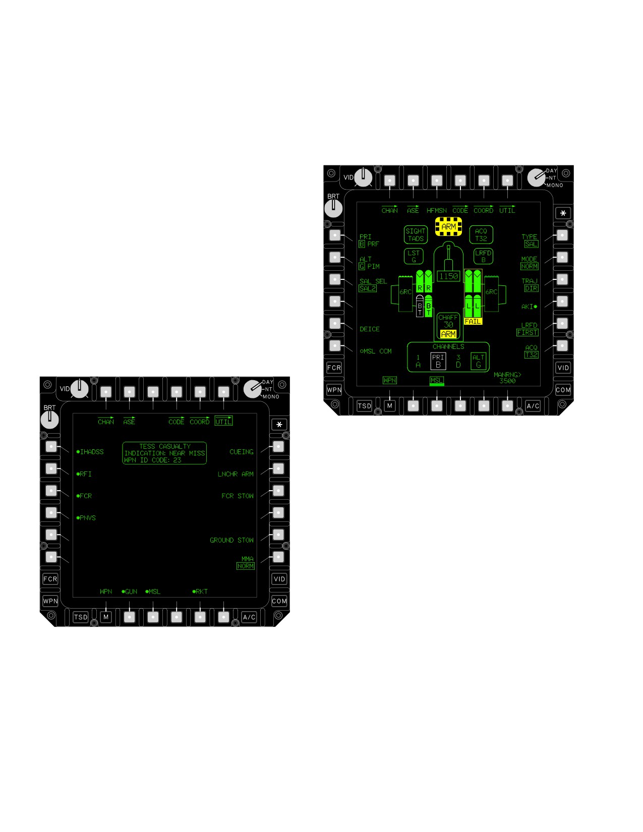
made available on the WPN UTIL Page (Fig 4-95).
LBA3016
Figure 4-96. AKI Button on WPN Page
When during TESS training the TECU determines that an
RTCA kill event has been revoked by administrative input
of a resurrect or reset status, the TECU will transmit the
resurrect or reset command to the aircraft and the follow-
ing will occur:
• The CIU will provide the aircrew with resurrect or
reset audio effect:
“SIMULATION IS RESET”
“SIMULATION IS RESURRECTED”
•
The RTCA status will be removed from the UFD.
• The RTCA status and weapon ID code will be
LBA3015
removed from the WPN UTIL Page.
• The resurrect or reset status will be displayed on
the UFD for 8 seconds:
Figure 4-95. RTCA Status on WPN UTIL Page
• “SIM RESET” - TESS has commanded the aircraft
to a reset state.
• If a kill status is received, the aircraft will be
inhibited from firing any weapon.
• “SIM RESURR” - TESS has commanded the
aircraft to a resurrect state.
• The TTM will power the external aircraft kill
indicator (AKI) to indicate the RTCA status.
• The aircraft will be permitted to fire any weapon.
Use or disclosure of this information is subject to the restriction(s) on the title page of this document.
4-100
TM 1-1520-251-10
• The TTM will power off the external AKI.
• 19 rockets for each installed and inventoried M260
launcher
• If a resurrect is received, the TECU will update the
weapon stores inventory with the same inventory
that was available before the kill was processed.
• 888 gun rounds
• If a reset is received, the TECU will update the
weapon stores inventory with the initial inventory
that was available upon power up.
Resident Hellfire launchers will be placed in the TME
mode resulting in the simulation of RF missiles on each
4.76 WEAPON TRAINING MODE
launch rail in which no missile was inventoried during ini-
tial missile inventory. The TME operation is described in
The weapon training mode is an emulation of weapon sys-
paragraph 4.74.7.
tems operation that allows aircrew training for all AH - 64D
weapon systems. The weapon training mode is activated
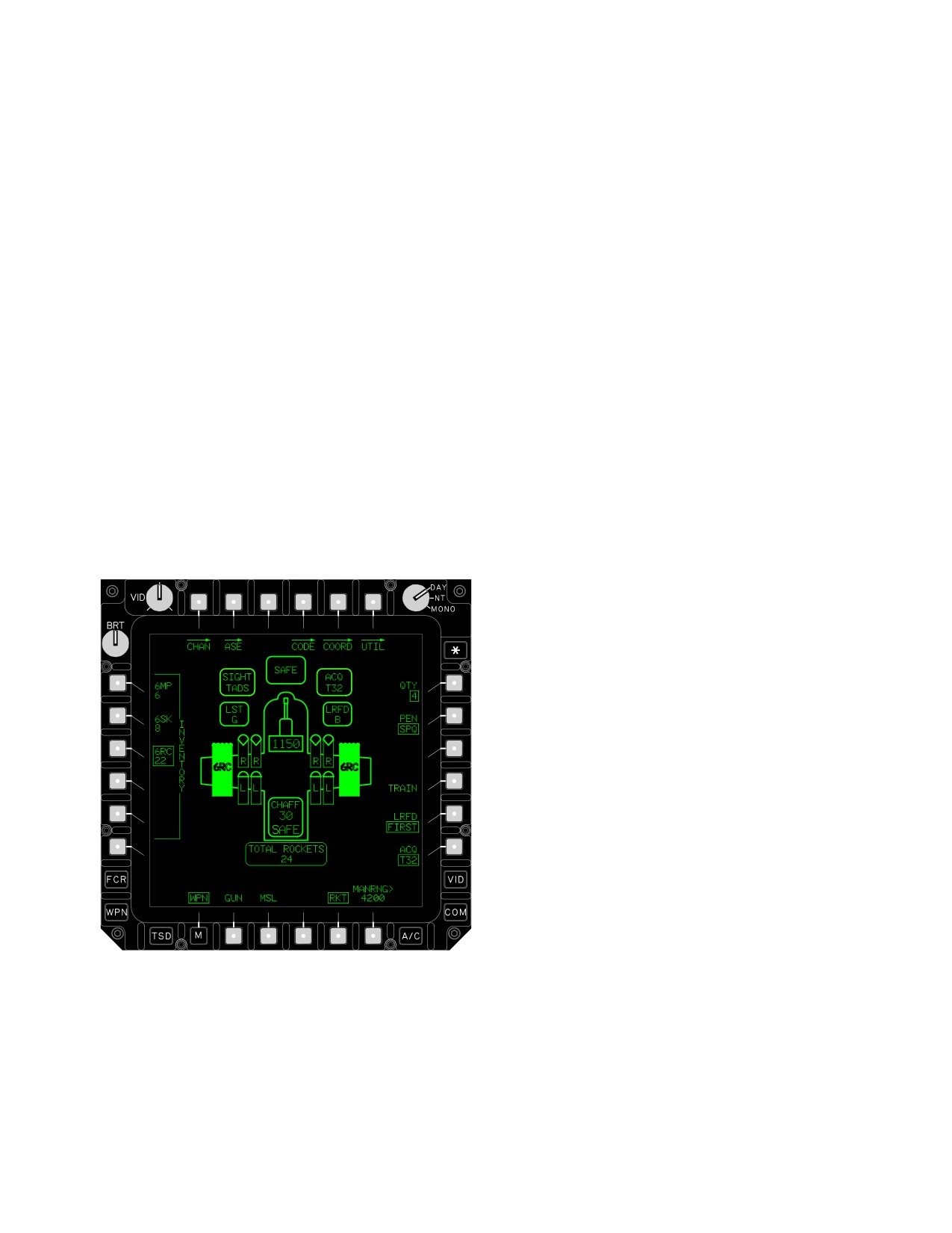
and deactivated using the TRAIN button (R4) on the WPN
page (Fig 4-97). This mode is not available when TESS is
Simulated inventories will decrement in response to valid
enabled. The aircrew can enter and exit the weapon train-
firing requests. Inventories are restored each time the
ing mode only when the armament control is in SAFE and
weapon training mode is activated. When SAL training
no weapon system is actioned. Weapon systems opera-
missiles are installed on a Hellfire launcher, all tactical
tions in the weapon training mode are as per the tactical
missiles will be made unavailable. Simulated inventories
design. Any faults or failures experienced by the systems
are not considered in aircraft gross weight and perfor-
will impact the weapon systems operation in the training
mance calculations. A data entry change to the gun
mode as it does in the tactical mode.
rounds count or the use of rocket ’spoofing’ devices will
adversely impact aircraft gross weight.
4.76.2 Symbology/HAD. A centered “T” will be dis-
played in the Hellfire constraints and rocket steering cur-
sor symbols when operating in the weapon training mode
and either of these weapons are actioned (same as
TESS, Figure 4-94). The HAD weapon inhibit field will dis-
play “SAFE” when in the training mode, a weapon system
is actioned and the armament control set to SAFE. Upon
setting the armament control to ARM, the weapon inhibit
field will change to “TRAINING”.
4.76.3 Sound Effects. When operating in the weapon
training mode, and a simulated Hellfire missile launch,
rocket launch, or gun fire occurs, the communications in-
terface unit (CIU) will provide the respective weapon
LBA1977A
launch/firing audio effect.
Figure 4-97. WPN Page TRAIN Button
4.76.4 Safety Considerations. The weapon training
4.76.1 Simulated Weapons Inventory. The armament
mode may be operated with live ammunition at the weap-
subsystem will adopt the following simulated weapon in-
on stations. As such, the weapon training mode employs
ventory when the weapon training mode is selected for
multiple safety features to minimize hazards associated
use:
with its use:
Use or disclosure of this information is subject to the restriction(s) on the title page of this document.
4-101
TM 1-1520-251-10
• Application of arm power to weapon stations is
9. CPG WAS - MSL. (Observe HAD messages
inhibited by both the SPs and WPs when the
and WPN page configuration/fault indications.)
weapon training mode is active. In addition,
existing continuous BIT algorithms ensure that
10. Pilot WAS - MSL. (Observe HAD messages
arm power and discrete firecommands are absent
and WPN page configuration/fault indications.)
at these stations when the weapon training mode
is in use. Detection of hazardous conditions via
11. GND ORIDE switch - OFF.
CBIT results in non - availability of the affected
weapon station.
4.78 AWS OPERATING PROCEDURES
• Launch events are simulated; no tactical launch/
firing command are issued to stores or to the gun
WARNING
when the weapon training mode is in use.
• The crew interface imposes a barrier on the
• If 300 or more rounds have been fired
weapon TRAIN button to minimize the potential for
in the preceding ten minutes, and a
inadvertent entry into the weapon training mode
stoppage occurs, personnel must re-
during a live - fire engagement. Likewise, the
main clear of the aircraft for 30 mi-
barrier logic minimizes the potential for accidental
nutes. Aircraft crewmembers should
exit of the weapon training mode during a simu-
remain in the aircraft and continue
lated engagement.
positive gun control.
4.77
WEAPONS OPERATIONAL CHECK
• Failure to adhere to the published gun
duty cycle may result in a catastrophic
NOTE
failure, loss of aircraft, injury or death.
Weapons initialization is used to verify go/
4.78.1 M230E1, 30mm Gun - FIRE GUN.
no-go status of the weapons using fault in-
dications and symbolic messages. It also
1.
WPN page - Select.
places the weapons in a condition that will
require minimal switch selection prior to en-
gagement.
2.
GUN button - Select.
1. SIGHT SELECT - (pilot - HMD) (CPG - TADS).
3.
GUN MODE and BURST LIMIT buttons - Select
As desired.
2. GND ORIDE switch - ON ( required on ground).
4.
Sight Select switch - Select as desired.
3. ARM/SAFE switch - ARM. (Arm power and in-
dications verified by both pilot and CPG.)
5.
Target - Acquire and track.
4. ARM/SAFE switch - SAFE.
6.
WAS - GUN.
5. CPG WAS - GUN. (Observe HAD messages
7.
A/S button - ARM.
and WPN page configuration/fault indications.)
8.
Range - Establish to target.
6. PLT WAS - GUN. (Observe HAD messages and
WPN page configuration/fault indications.)
9.
HAD messages - Observe.
7. CPG ORT WAS - RKT. (Observe HAD mes-
10.
Weapons trigger switch - Press, continue to fire
sages and WPN page configuration/fault indica-
as required.
tions.)
8. PLT WAS - RKT. (Both seats observe COOP
11.
WAS - Deselect as desired.
HAD messages and WPN page configuration/
fault indications.)
12.
A/S button - As desired.
Use or disclosure of this information is subject to the restriction(s) on the title page of this document.
4-102
TM 1-1520-251-10
4.78.2 M230E1, 30mm Gun - Dynamic Harmonization
5. Sight Select switch - Select as desired.
(CPG Only).
6. CPG - Acquire and track target.
NOTE
7. ORT WAS - RKT.
Harmonization procedures should be ac-
8. Pilot WAS - RKT.
complished between 500 to 1000 meters
from the target.
9. A/S button - ARM.
1.
WPN page - Select.
10. Range - Establish to target.
2.
GUN button - Select.
11. Pilot - Align rocket steering cursor.
12. HAD messages - Observe.
3.
HARMONIZE button - Select.
13. Pilot Weapons trigger switch - Press.
4.
Sight Select switch - TADS.
14. ORT WAS - Deselect as desired.
5.
Target - Auto track in NFOV DTV/FLIR.
15. Pilot WAS - Deselect as desired.
6.
WAS - GUN.
16. A/S button - As desired.
7.
A/S button - ARM.
4.79.2 Fire Rockets - PILOT OR CPG ONLY MODE.
8.
Range to target - Establish Laser or Manual.
1. WPN page - Select.
2. INVENTORY button - As desired.
9.
Weapons trigger switch - Press. Observe Mean
Point of Impact (MPI) of rounds.
3. QTY button - As desired.
10.
MAN TRK thumbforce controller - Position
4. PEN button - As desired.
dashed reticle over MPI.
5. Sight Select switch - Select as desired.
11.
STORE/UPDATE switch - Store.
6. Target - Acquire and track.
12.
GUN DH NOT VALID status window - Verify not
7. WAS - RKT.
displayed. If present repeat steps 3 through 12.
8. A/S button - ARM.
13.
WAS - Deselect as desired.
9. Range - Establish to target.
14.
A/S button - As desired.
10. Rocket steering cursor - Align.
15.
Sight Select switch - Select as desired.
11. HAD messages - Observe.
4.79 AERIAL ROCKET SUBSYSTEM OPERATING
12. Weapons trigger switch - Press.
PROCEDURES
13. WAS - Deselect as desired.
4.79.1 Fire Rockets - COOPERATIVE MODE.
14. A/S button - As desired.
1. WPN page - Select.
4.80 LONGBOW HELLFIRE MISSILE SYSTEM
OPERATING PROCEDURES
2. INVENTORY button - As desired (CPG).
NOTE
3. QTY button - As desired (CPG).
If FCR was sight selected during this proce-
dure, ensure the MSL TYPE option is reset
4. PEN button - As desired (CPG).
to SAL.
Use or disclosure of this information is subject to the restriction(s) on the title page of this document.
4-103
TM 1-1520-251-10
4.80.1 SAL Missile Engagement (NORMAL - LOBL).
3. TYPE button - SAL.
1.
WPN page - Select.
4. PRI button - Select primary channel as desired.
5. ALT button - Select alternate channel as desi-
2.
MSL button - Select.
red.
3.
TYPE button - SAL.
6. SAL SEL button - Select type of SAL missile as
desired.
4.
PRI button - Select primary channel as desired.
7. MODE button - NORM or MAN.
5.
ALT button - Select alternate channel as desi-
red.
NOTE
6.
SAL SEL button - Select type of SAL missile as
If trajectory is set to LO or HI, ensure that
desired.
ACQ select is the desired target.
8. TRAJ button - Select as desired.
7.
MODE button - NORM or MAN.
9. WAS - MSL.
8.
WAS - MSL.
10. A/S button - ARM.
9.
A/S button - ARM.
11. WPN page or AND - Observe for missile selec-
10.
WPN page or AND - Observe for missile selec-
tion, coding, and ready status.
tion, coding, and ready status.
12. Aircraft - Establish in constraints.
11.
Target - Lase, observe for proper missile track
status.
13. HAD messages - Observe.
12.
Pilot - Establish aircraft in constraints.
NOTE
If performance constraint criteria are not
13.
HAD messages - Observe.
met, the 2nd detent of the weapons trigger
switch may be used to override constraint
NOTE
inhibits and fire missile. Safety inhibits can-
If performance constraint criteria are not
not be overridden.
met, the 2nd detent of the weapons trigger
switch may be used to override constraint
14. Weapons trigger switch - Press.
inhibits and fire missile. Safety inhibits can-
not be overridden.
15. Target - Lase or call for remote designator in ad-
equate time for terminal guidance.
14. Weapons trigger switch - Press.
16. WAS - Deselect as desired.
15. LRFD trigger - Release on missile impact.
17. A/S button - As desired.
16. WAS - Deselect as desired.
4.80.3 SAL Missile Engagement (RIPPLE - LOBL).
17. A/S button - As desired.
1. WPN page - Select.
4.80.2 SAL Missile Engagement (NORMAL - LOAL).
2. MSL button - Select.
1. WPN page - Select.
3. TYPE button - SAL.
2. MSL button - Select.
4. PRI button - Select primary channel as desired.
Use or disclosure of this information is subject to the restriction(s) on the title page of this document.
4-104
TM 1-1520-251-10
5. ALT button - Select alternate channel as desi-
4.80.4 SAL Missile Engagement (RIPPLE - LOAL).
red.
1.
WPN page - Select.
6. SAL SEL button - Select type of SAL missile as
2.
MSL button - Select.
desired.
3.
TYPE button - SAL.
7. MODE button - RIPL.
4.
PRI button - Select primary channel as desired.
8. TRAJ button - Select as desired.
5.
ALT button - Select alternate channel as desi-
9. WAS - MSL.
red.
6.
SAL SEL button - Select type of SAL missile as
10. A/S button - ARM.
desired.
11. WPN page or AND - Observe for missile selec-
7.
MODE button - RIPL.
tion, coding, and ready status.
8.
TRAJ button - Select as desired.
12. Pilot - Establish aircraft in constraints.
9.
WAS - MSL.
13. HAD messages - Observe.
10.
A/S button - ARM.
NOTE
11.
WPN page or AND - Observe for missile selec-
If performance constraint criteria are not
tion, coding, and ready status.
met, the 2nd detent of the weapons trigger
12.
Pilot - Establish aircraft in constraints.
switch may be used to override constraint
inhibits and fire missile. Safety inhibits can-
13.
HAD messages - Observe.
not be overridden.
NOTE
14. Weapons trigger switch - Press and release.
If performance constraint criteria are not
met, the 2nd detent of the weapons trigger
15. Target - Lase and continue lasing until missile
switch may be used to override constraint
impact.
inhibits and fire missile. Safety inhibits can-
not be overridden.
16. Pilot - Establish aircraft in constraints for alter-
nate channel.
14. Weapons trigger switch - Press and release.
15. Target - Lase or call for terminal guidance.
17. HAD messages - Observe.
16. Pilot - Establish aircraft in constraints for alter-
nate channel.
18. Weapons trigger switch - Press and release.
17. HAD messages - Observe.
19. Target - Lase or call for terminal guidance.
18. Weapons trigger switch - Press and release.
19. Target - Lase or call for terminal guidance.
NOTE
NOTE
Execute steps 12 through 19 until desired
number of missiles has been fired.
Execute steps 12 through 19 until desired
number of missiles has been fired.
20. WAS - Deselect as desired.
20. WAS - Deselect as desired.
21. A/S button - As desired.
21. A/S button - As desired.
Use or disclosure of this information is subject to the restriction(s) on the title page of this document.
4-105
TM 1-1520-251-10
4.80.5 RF Missile Engagement (Sight FCR
).
12. HAD messages - Observe.
1. WPN page - Select.WAS
NOTE
2. MSL button - Select.
If performance constraint criteria are not
met, the 2nd detent of the weapons trigger
3. TYPE button - RF.
switch may be used to override constraint
4. MSL PWR button - As desired.
inhibits and fire missile. Safety inhibits can-
not be overridden.
5.
2nd TARGET INHIBIT button - As desired.
13. Weapons trigger switch - Press and release.
6. LOBL INHIBIT button - As desired.
14. WAS - Deselect as desired.
7. Sight Select switch - Select LINK if visual identi-
fication desired.
15. A/S button - As desired.
8. WAS - MSL.
4.80.7 RFHO Send.
9. A/S button - ARM.
1. NTS - Desired target.
10. WPN page or AND - Observe for missile selec-
tion, coding, and ready status.
2. RFHO button - Select.
11. Aircraft - Establish in constraints.
3. Zone Member Callsign button - Select.
12. HAD messages - Observe.
4. SEND button - Select.
NOTE
4.80.8 RF Missile Engagement (RFHO).
If performance constraint criteria are not
1. UFD - Observe RFHO advisory.
met, the 2nd detent of the weapons trigger
2. TSD page - Select.
switch may be used to override constraint
inhibits and fire missile. Safety inhibits can-
3. REC button - Select.
not be overridden.
4. TSD page - Observe target and NTS symbol.
13. Weapons trigger switch - Press and release.
5. Pilot - Establish aircraft in position for launch.
14. WAS - Deselect as desired.
6. Sight Select switch - FCR.
15. A/S button - As desired.
7. WPN page - Select.
4.80.6 RF Missile Engagement (Sight - TADS).
8. TYPE button - Verify default to RF.
1. Sight Select switch - TADS.
9. WAS - MSL.
2. WPN page - Select.
10. A/S button - ARM.
3. MSL button - Select.
11. WPN page or AND - Observe for missile selec-
tion, coding, and ready status.
4. TYPE button - RF.
12. Pilot - Establish aircraft in constraints.
5. MSL PWR button - As desired.
NOTE
6.
2nd TARGET INHIBIT button - As desired.
If performance constraint criteria are not
7. LOBL INHIBIT button - As desired.
met, the 2nd detent of the weapons trigger
8. WAS - MSL.
switch may be used to override constraint
inhibits and fire missile. Safety inhibits can-
9. A/S button - ARM.
not be overridden.
10. Target - Track and lase target for at least 3 se-
13. Weapon trigger switch - Press and release.
conds or until HAD message TARGET DATA?
blanks.
14. WAS - Deselect as desired.
11. Aircraft - Establish in constraints.
15. A/S button - As desired.
Use or disclosure of this information is subject to the restriction(s) on the title page of this document.
4-106
Change 2
TM 1-1520-251-10
4.80.9 RFI Only Operation - Pinned MMA.
12.
IDM auto transmit capability - Set as required.
1. Manually rotate MMA until forward alignment
a. SET page IDM INHBT - Deselect as re-
mark is aligned with pedestal alignment mark.
quired: IDM INHIBIT advisory is not dis-
played and IDM INHIBIT button is non OIP.
NOTE
or
BLK 1
perform b,c, and d.
MMA movement may be required to engage
locking pin.
b. AUTO REPLY - Set as required.
2.
Press locking pin detent and push locking pin
c. AUTO ACK - Set as required.
until spring is compressed. Hold locking and re-
lease detent. Verify MMA will not move and lock-
d. TACFIRE Net - Set as required.
ing pin remains engaged.
13.
HF RADIO - Set as required.
3.
FCR UTIL page - Verify PINNED.
a. HF RADIO GND OVRD - On or Off.
4.
RFI button - ON.
and/or
4.80.10
Rapid Rearming.
b. HF RADIO SILENT - On or Off.
1.
WPN UTIL page - MSL, RKT, GUN - OFF.
4.80.11
Armament Safing and Postflight Procedures.
2.
A/S button - SAFE.
3.
GND ORIDE button - OFF.
WARNING
4.
TAIL WHEEL button - LOCK.
• Do not preflight or postflight until ar-
5.
PARK BRAKE - Set.
mament systems are safe.
6.
Armament and pylon safety pins - Installed.
• During preflight and after all live fires,
when the AWS has been used, the bar-
7.
Launcher A/S switch(es) - SAFE.
rel will be inspected by the crew for
8.
IDM auto transmit - Disable
cracks.
a. SET page IDM INHBT - Select, IDM IN-
If armament system has been used, check as follows:
HIBIT advisory is displayed.
1. Right EFAB - Open. Check feed system for
rounds.
or
BLK 1
perform b,c, and d.
2. Gun chute assembly - Check for rounds.
b. AUTO REPLY - Off.
3. Bolt status indicator - FEED (green range).
c. AUTO ACK - Off.
4. Transfer door - Open. Check bolt is to rear, no
d. TACFIRE Net - Not tuned.
rounds in transfer assembly, and chamber clear.
9.
HF RADIO - Disable auto radio transmission
5. Transfer door - Secure.
capability.
6. AWS - General condition and security. Check
a. HF RADIO GND OVRD - Off.
for leaks and proper piston index groove indica-
tion.
or
7. Launcher ARM/SAFE switches - SAFE.
b. HF RADIO SILENT - On.
8. Wing stores pylon - Check for unexpended ord-
10.
Rearming - Monitor.
nance.
11.
Launcher A/S switch(es) - ARM.
9. Armament and pylon safety pins - Install.
Use or disclosure of this information is subject to the restriction(s) on the title page of this document.
Change 3
4-107
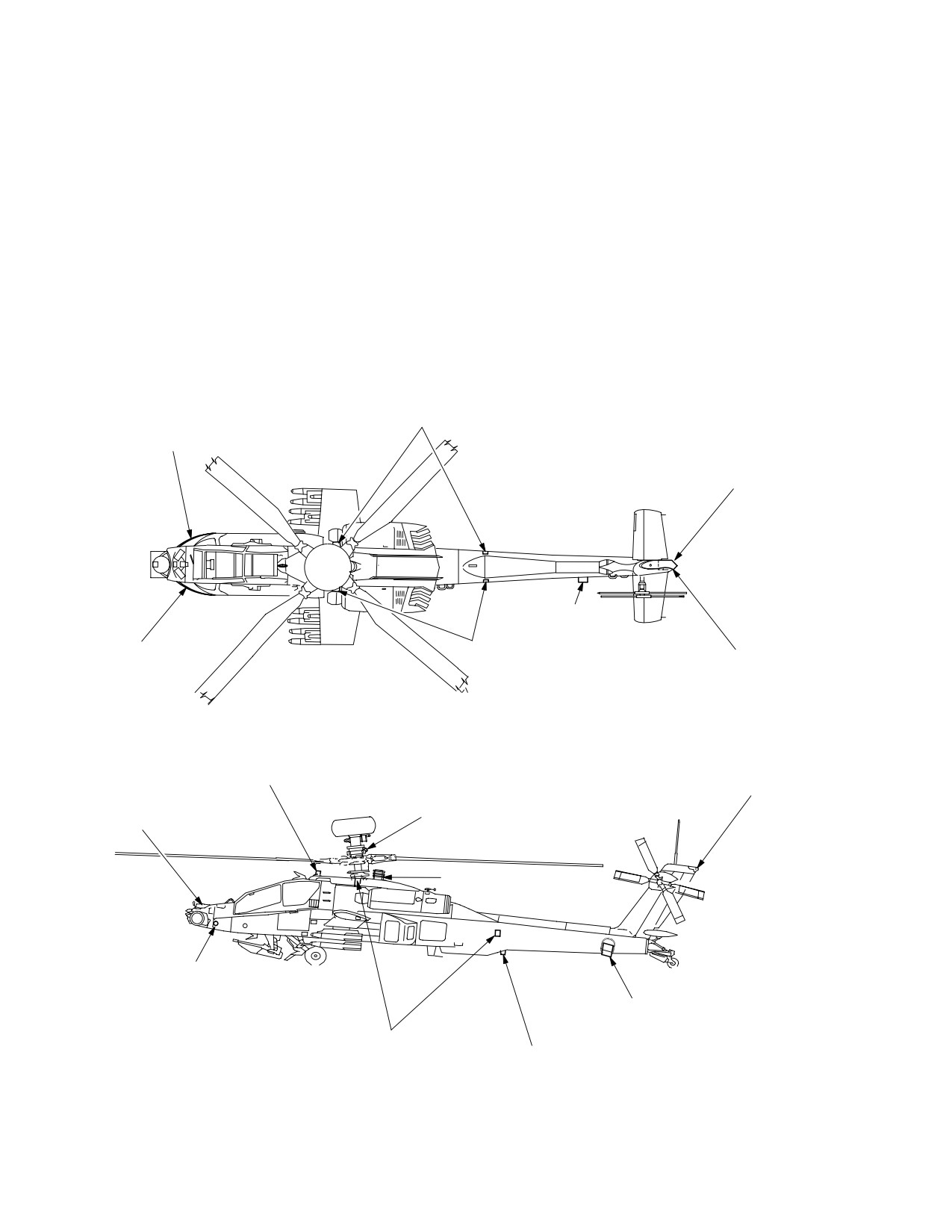
TM 1-1520-251-10
Section III. ACTIVE AND PASSIVE DEFENSE EQUIPMENT
4.81 INTRODUCTION
Defense Subsystems consists of the following compo-
nents:
INTRODUCTION. Active and Passive Defense Equip-
• AN/APR-39A(V)4 Radar Signal Detecting Set
ment (fig 4-98) consists of active countermeasures and
• AN/AVR-2A Laser Signal Detecting Set
electronic passive threat detection as well as airframe fea-
• AN/APR-48A Radar Frequency Interferometer
tures such as armor, IR paint, and the Wire Strike Protec-
(RFI)
tion System (WSPS). This section describes the Active
4.81.2 Active Defense Subsystems. The Active De-
and Passive Defense Subsystems that are operated from
fense Subsystems consists of the following components:
dedicated controls and the MPD. There is no power up
• AN/ALQ-136(V)5 Radar Jammer
BIT for the ASE equipment.
• AN/ALQ-144A(V)3 Infrared Jammer (IRJAM)
4.81.1 Passive Defense Subsystems. The Passive
• M-141 Chaff Dispenser (CHAFF)
LASER DETECTION SYSTEM
RADAR DETECTION
SENSORS (AVR−2A)
SYSTEM (RDS)
SENSOR (APR−39A(V)4)
RADAR DETECTION SYSTEM (RDS)
SENSOR (APR−39A(V)4)
CHAFF DISPENSER (M141)
RADAR DETECTION
LASER DETECTION SYSTEM
SYSTEM (RDS)
SENSORS (AVR−2A)
RADAR DETECTION SYSTEM (RDS)
SENSOR (APR−39A(V)4)
SENSOR (APR−39A(V)4)
RADAR JAMMER
RECEIVE ANTENNA
RADAR DETECTION SYSTEM (RDS)
(ALQ136(V)5)
SENSOR (APR−39A(V)4) (2 PLACES)
RADAR JAMMER
TRANSMIT ANTENNA
RADAR FREQUENCY INTERFEROMETER (RFI)
(ALQ136(V)5)
(APR−48A)
IR JAMMER TRANSMITTER
(ALQ−144A)
RADAR DETECTION
SYSTEM (RDS)
SENSOR (APR−39A(V)4)
(2 PLACES)
CHAFF DISPENSER (M141)
LASER DETECTION SYSTEM
SENSORS (AVR−2A)
RDS BLADE ANTENNA
(4 PLACES)
(APR−39A(V)4)
LBA1969
Figure 4-98. ASE Equipment Locations
Use or disclosure of this information is subject to the restriction(s) on the title page of this document.
4-108
TM 1-1520-251-10
4.82 AN/APR-39A(V)4 RADAR SIGNAL DETECTING
• Threat Count
SET
• Threat Priority
• Threat Type
CAUTION
• New Threat Signal - Bold for 3 Seconds
• Threat Signal No Longer Detected - Ghosted for
To prevent damage to the receiver detec-
10 Seconds
tor crystals, assure that the radar warn-
• Threat Mode (Search, Acquisition, Track, or Lock -
ing set antennas are at least 60 meters
On/Launch)
from active ground radar antennas or 6
meters from active airborne radar anten-
• Correlated C/D bank Threat
nas. Allow an extra margin for new, un-
• Threat Azimuth
usual, or high power emitters.
In addition, the digital processor also generates a corre-
4.82.1
System Description. The AN/APR-39A(V)4
sponding computer-synthesized voice threat message
Radar Signal Detecting Set (RSDS) is a passive electron-
which is sent to the communication interface unit for dis-
ic warfare system that provides visual and aural indica-
semination to the pilot and CPG headsets. Selection and
tions of the presence of and bearing to active radar trans-
volume control of this audio is provided by the commu-
mitters. The system is omnidirectional and provides for
nication control panel in each crewstation. If the received
signal parameters do not match a threat in the EID files,
the detection, identification, classification, and prioritiza-
the digital processor generates the threat data for a “U” to
tion of pulse and pulse doppler radar emitters and also
indicate an unknown threat. The digital processor also
supplies moding and bearing information about these
processes threat data inputs from the laser detecting set
emitters. The RSDS detects those pulse radar signals
AN/AVR-2A for display on the MPDs and annunciation
usually associated with hostile fire control radars operat-
over the ICS. When dense signal environments cause the
ing in the C/D and E-M frequency bands. These pulse ra-
system to operate in a degraded (reduced sensitivity)
dar signals are seen as potential threats to the helicopter
mode, the system informs the operator with the voice
and are displayed as symbols on the MPDs. The system
message “Threat Detection Degraded,” heard over the
also generates computer-synthesized voice threat mes-
ICS. When the system sensitivity returns to normal, the
sages for audible indications of potential threats. These
voice message “Threat Detection Restored” will be enun-
voice threat messages, heard over the Intercommunica-
ciated over the ICS.
tions System (ICS), and the display symbols, seen on the
MPDs, occur simultaneously to indicate the type of threat,
4.83 AN/AVR-2A LASER SIGNAL DETECTING SET
threat mode, and its relative bearing to the helicopter. The
system consists of a digital processor, two radar receivers
4.83.1 AN/AVR-2A Laser Detecting Set (LDS) System
(one forward and one aft), four hi-band spiral antenna-de-
Description. The AN/AVR-2A Laser Detecting Set
tectors (two forward and two aft), and a lo-band blade an-
(LDS) is a passive electronic warfare system that detects,
tenna. The RSDS employs a removable User Data Mod-
locates, and identifies hostile laser-aided weapon threats
ule (UDM) which is mounted in the top of the digital
fired from both airborne and ground-based platforms. The
processor. The UDM contains the classified portion of the
LDS is a frequency extension of the RSDS and interfaces
system Operational Flight Program (OFP) and the classi-
with the RSDS to function as an integrated Radar Laser
fied Emitter Identification Data (EID) files. The EID files
Warning Receiver (RLWR). The system detects optical
contain the threat library which includes threat signal
radiation illuminating the helicopter, processes this laser
parametric data.
data into laser threat messages, and sends these mes-
sages to the RSDS digital processor. The digital proces-
4.82.2 System Operation. The RSDS uses the four hi-
sor processes these inputs to provide for both visual and
band antenna-detectors and the lo-band (C/D) blade an-
aural threat indications for the system. The LDS can also
tenna to receive RF energy from pulse radars. Each of the
be used with both the RSDS and the Air-to-Ground En-
three spiral elements within an antenna-detector receive
gagement System (AGES) to provide an engagement
RF signals in their respective band and supply it to the de-
simulation system, in the operational training mode. The
tector circuits. A radar warning receiver track file that is
system is composed of five components: four laser sensor
transferred from the digital processor to the display pro-
units and an Interface Unit Comparator (IUC). The four
cessors contains threat information from up to 10 RLWR
sensor units are strategically located around the helicop-
detected emitters and includes the following data:
ter with two mounted forward, facing forward and two
Use or disclosure of this information is subject to the restriction(s) on the title page of this document.
4-109
TM 1-1520-251-10
mounted aft, facing aft. Each sensor unit provides a 100°
a. Training. During training operation, the LDS op-
Field-Of-View (FOV) and ±45° of coverage in elevation.
erates as a detecting system in a MILES environment and
This configuration provides for 360° coverage in azimuth
the operating software within the LDS does not recognize
and ±45° in elevation about the helicopter with substantial
.904 micron gallium arsenide (GaAs) MILES laser hits as
overlap. Each sensor unit contains four separate laser de-
actual laser threats.
tectors. They are located under a special optical window
and supply coverage of three different spectral regions:
b. Tactical. During tactical operation, the LDS de-
Electro-Optical (EO) bands I, II, and III. Two detectors are
tects, identifies, and characterizes three different types of
employed in the band III region, the band IIIA and band
optical signals. Each sensor unit provides laser threat
IIIB detectors, to provide the required band III detection
detection in three different spectral bands; band I, band II,
coverage.
and band III. When a sensor unit detects optical, coherent
radiation within its FOV, it provides band and pulse char-
acteristics as laser threat data to the IUC. The IUC further
processes this threat data, thus comparing received sig-
4.83.2 System Operation. The sensor units perform
nal characteristics with stored parameters. It then deter-
the actual laser detection function for the system and con-
mines the existence of a laser threat, threat type, and
tain the necessary electronics to process detected laser
Angle-Of-Arrival (AOA) (quadrant resolution only).
signals. If a validated laser signal is detected, a threat
message containing the laser type (band I, II, or III) is sent
This threat data is sent as laser threat messages to the
to the IUC for processing. Each sensor unit contains opti-
RSDS digital processor for manipulation to provide visual
cal and electrical Built-In Test (BIT) electronics to perform
threat indications on the MPD ASE and TSD pages and
a self-test upon command from the IUC. When a self-test
aural voice threat messages over the helicopter ICS. Both
command is received, the sensor unit disables detection
the visual and aural threat indications provide threat type
of all externally generated signals and performs a self-
and relative position information to the crewmembers.
test. When the self-test is completed, the appropriate
pass or fail message is sent to the IUC for processing and
4.84 AN/APR-48A RADAR FREQUENCY
normal operation is resumed. The IUC is located in the LH
INTERFEROMETER (RFI)
aft avionics bay. It is mounted just forward of the RSDS
digital processor with which it directly interfaces. The IUC
4.84.1 System Description. The AN/APR-48A Radar
provides the control and timing necessary for the interface
Frequency Interferometer (RFI) is a passive Electronic
with the sensor units. It also provides the interface with the
Support Measure (ESM) system that provides for the
RSDS. The LDS was designed to operate in conjunction
detection, acquisition, identification, classification, loca-
with the RSDS, therefore, being an integral part of the
tion, and prioritization of radar emitters. The system de-
RSDS. The IUC provides the majority of the wiring inter-
tects and processes pulse, pulse doppler, and Continuous
face between the RSDS and the associated helicopter
Wave (CW) radar signals operating in a currently classi-
systems. If the IUC is removed from the helicopter, a
fied frequency range. The RFI is primarily an offensive
jumper box must be installed in the system or an alternate
system providing narrow FOV target cueing for onboard
connector configuration employed to permit the RSDS to
and offboard sights/sensors for the accurate and timely
operate. The LDS employs a removable User Data Mod-
employment of weapons. It also supplies highly effective
ule (UDM) which is mounted in the face of the IUC. The
defensive threat warning capability for the ASE suite. The
UDM contains the classified operational software required
high sensitivity of the system provides for not only main
for tactical operation of the system. This software gets
beam signal detection, but also sidelobe and/or backlobe
downloaded into volatile memory within the sensor units
signal detection as well. The system is designed to detect
during system power-up and initialization, and the sensor
Low Probability of Intercept (LPI) signals and to detect the
units then become classified. When system power is re-
threat long before it detects the helicopter. It is capable of
moved, the sensor units zeroize the classified software
threat acquisition well beyond threat lethal range and pro-
and become unclassified components. The removal of
vides for masked detection of threats based on its mount-
system power and the UDM for the IUC effectively declas-
ing location above the rotor mast. The RFI provides for
sifies the system. The LDS has the capability to operate in
360° coverage about the helicopter for coarse DF and
two modes, training and tactical. In the training mode, the
instantaneous 90° coverage for precision fine DF. The
system operates with AGES in the Multiple Integrated La-
coarse DF routing employs amplitude DF techniques and
ser Engagement System (MILES) to provide the crew-
utilizes four coarse DF antenna elements, comparing the
members with a realistic combat tactical training system
amplitude of adjacent antenna channels to determine sig-
that closely simulates the effect of weapon engagements.
nal AOA. The system utilizes a five antenna baseline for
Use or disclosure of this information is subject to the restriction(s) on the title page of this document.
4-110
TM 1-1520-251-10
the phase interferometry to perform the accurate fine DF
• RF, PRI, Sigma PRI, PW Limits
(8 Specific
routine Pulse Spacing (PS).
Parameters)
• Scan Type
• Parametric Volume (Ambiguity Resolver)
• Scan Rate
• Priority
• Time In Main Beam (TIMB)
• Identification Code
• Flags ( Hostile/Friendly, Airborne, CW, etc.)
4.84.2 System Operation. The identification proces-
sing allows for the handling of multi-beam emitters that
4.85 AN/ALQ-136(V)5 RADAR JAMMER
output more than one type of RF signal either simulta-
COUNTERMEASURES SET (RJAM)
neously or on a time scheduled basis. The RFI correlates
these signals so that only one threat ID is displayed with
4.85.1 System Description. The AN/ALQ-136(V)5 Ra-
its corresponding moding information (search, acquisition,
dar Jammer Countermeasures Set (RJAM) is an active
track, lock-on/launch, etc.) on the MPD. The sophisticated
Electronic Counter Measure (ECM) system designed to
signal processing allows for the detection and identifica-
protest the helicopter against certain Anti-Aircraft Artillery
tion of frequency and Pulse Repetition Interval (PRI) agile
(AAA) and Surface-to-Air Missile (SAM) threats. It is a
emitters. The RFI processor controls the RFI receiver and
self-contained system that receives, detects, analyzes,
the RFI antenna to detect and classify threats. It develops
and processes those pulse radar signals usually
both coarse and fine azimuth locations of emitters, based
associated with hostile fire control radars, and initiates the
on aspect angle and threat frequency. The RFI antenna
appropriate jamming in an attempt to effectively counter
consists of two array sets; a coarse array set and a fine
the detected threats. The RJAM system consists of a Re-
array set. The coarse array provides 360° coverage in azi-
ceiver/Transmitter (R/T) and two antennas; one antenna
muth about the helicopter, while the fine array phase an-
used for reception and one antenna used for transmis-
tennas are switched to forward, left, or right channels for
sion. The system performs effectively as both a detection
Intermediate Frequency (IF) processing. The RFI receiver
system and a jamming system for pulse radar threats. The
measures pulse parameters from four inputs received
receive antenna receives pulse radar signals and supplies
from the RFI antenna providing 360° coverage. The sys-
them to the R/T receiver circuits via a special low-loss
tem performs accurate parametric data measurement for
coaxial cable. The receiver processes this Radio Fre-
precise, unambiguous identification and classification of
quency (RF) energy and extracts the video (pulses) from
detected emitters. The threat parametric data scrutinized
it. This video is filtered, limited, amplified, and detected,
by the processor for detected signals includes:
and provided to the processor section of the R/T for analy-
• Frequency
sis. The processor compares the resultant video with the
stored threat signal parameters to determine whether the
• Bandwidth
received signal originated from a threat. These signal pa-
rameters include:
• Pulse Width (PW)
• Pulse Width
The emitter acquisition process involves the evaluation of
• Pulse Spacing
received pulse parameters and the sorting of these pulse
parameters into emitters. Once emitter parameter mea-
• Pulse Repetition Interval
surement is complete, the emitters are identified utilizing a
• Signal Strength
threat library stored on the UDM. The system must then
resolve multiple matches and perform the correlation of
• Modulation Type
multiple signals emanating from one emitter. The UDM is
mounted in the face of the RFI processor. It contains the
• Center Frequency
classified portion of the operational software, a Dwell Se-
quence Monitor Table (DSMT), and an Emitter ID table
If it is determined that a threat exists, the processor quer-
(EIDT). The DSMT controls the sequence of RF band
ies the stored jamming parameters table for the appropri-
monitoring, with each entry in the table containing a fre-
ate jamming profile. If one exists, the jamming parameters
quency band at which to dwell, a length of time in which to
are extracted, to include center frequency, modulation
dwell, and the number of sort windows. The EIDT accom-
type, and jamming technique, and sent to the transmitter
modates 100 threat entries with each entry containing the
section. The transmitter section generates the appropriate
following information:
jamming signals and applies them to the transmit antenna
Use or disclosure of this information is subject to the restriction(s) on the title page of this document.
4-111
TM 1-1520-251-10
for radiation via another low-loss coaxial cable. The Sys-
4.86 AN/ALQ-144A(V)3 INFRARED JAMMER
tem can detect, process, and jam multiple threats in a mul-
COUNTERMEASURES SET (IRJAM)
tiplex fashion using one set of antennas; however, the cur-
rent system configuration only provides for forward sector
WARNING
coverage for pulse radar threats.
Do not continuously look at the infrared
countermeasures transmitter during op-
eration, or for a period of 1 minute from a
distance of less than 3 feet. Skin expo-
WARNING
sure to countermeasure radiation for
longer than 10 seconds at a distance
less than 4 inches shall be avoided.
The AN/ALQ-136(V)5 system poses a po-
tential RF radiation hazard to personnel
CAUTION
due to its operating frequency range and
• The infrared countermeasures set (IR
transmitter output power. When the sys-
Jammer) should be operated for a
tem is powered up, personnel should re-
minimum of 15 minutes after energiz-
main clear of the transmit antenna by a
ing the system, otherwise life of the
minimum of 10 feet to prevent overexpo-
source may be drastically shortened.
sure to high frequency RF radiation and
• The IR jammer can be damaged if the
its corresponding effects.
IR jammer is not turned off for one
minute via the MPD prior to removing
power from the aircraft.
4.85.2 System Operation. The system radiates during
4.86.1 System Description. The AN/ALQ-144A(V)3
self-test (at a reduced power setting) and when stimulated
Infrared Jammer (IRJAM) is an active infrared counter-
by a threat signal while in the operate mode. The RJAM
measure set that operates as an omnidirectional IR trans-
receiver/transmitter contains a WAR/TNG switch which is
mitter to jam heat-seeking IR missiles. The system con-
located on the face of the unit. The switch is a lever-
sists of an IR transmitter located on the fairing
locked, two position switch which is safety wired in the de-
immediately aft of the rotor mast. The transmitter consists
sired position.
of an IR source, low and high speed modulators, covert
window, and housing. The transmitter generates IR ener-
gy, modulates it, and then passes it through the covert
window in the form of invisible IR energy. The transmis-
a. Training. In a training environment, the switch is
sion of unwanted wavelengths of electromagnetic energy,
safety wired in the TNG position. With TNG selected, the
such as visible light, is blocked by the covert windows.
system provides very limited frequency band coverage,
The radiation is modulated mechanically at low and high
frequencies. This IR energy is used to confuse IR seeking
utilizes non-operational test programs, and generates un-
missiles.
classified, non-operational jamming signals. The primary
purpose of the training mode is to exercise the system in
4.86.2 System Operation. The transmitter requires
a peacetime environment without compromising its actual
approximately a 1 minute warm-up period. The IR jammer
operational capability, which is classified.
is equipped with the following switches and indicators
which can be accessed and observed when the BIT indi-
cator panel is removed from the transmitter. RST/FXD/
SWP Switch - allows the operator to reset the BIT indica-
b. Tactical. In a wartime environment, the switch is
tors (RST), select fixed (FXD) frequency mode of
safety wired in the WAR position. With WAR selected, the
operation, and select sweep (SWP) frequency mode of
system provides full-up operational capability to include
operation. After using this switch to reset the BIT indica-
complete frequency band coverage, operational ECM
tors, ensure that the switch is set to the required jam pro-
programs, and actual jamming signals.
gram mode (FXD or SWP).
Use or disclosure of this information is subject to the restriction(s) on the title page of this document.
4-112
Change 4
TM 1-1520-251-10
Jam Program Selector Switch - this thumb wheel switch
screws. The retainer plate contains slots to permit the im-
selects the jam program for transmitter operation. Jam
pulse cartridges to mate with the breech plate contact pins
Program Indicator - this indicator displays the selected
and grounding clips to enable electrical contact to fire the
jam program through an opening in the wall of the card
cartridges.
cage. Elapsed Time Indicator - this indictor monitors the
operation time of the unit and provides a digital readout in
c. Chaff Safety Switch. The chaff safety switch is
hours.
located on the tailboom about 3 inches forward of the
chaff dispenser and provides another means of safing the
4.87 M141 GENERAL PURPOSE AIRCRAFT
system to prevent inadvertent expenditure of impulse/
DISPENSER (CHAFF)
chaff cartridges. When the safety pin is installed in the
switch, chaff arm power is disconnected from the chaff
dispenser and the chaff test connector. When the safety
WARNING
pin is removed from the switch, arm power is distributed to
both the dispenser and the test connector. The SP serves
Avoid exposure to high concentrations
as the primary processing center for the chaff dispenser
of chaff; high concentrations of chaff can
system management control. The SP monitors direct sta-
cause temporary irritation to eyes and
tus inputs from the cyclic chaff dispense switches and
throat.
controls the firing of chaff based on these inputs. The SP
receives chaff control selections made on the MPDs from
4.87.1 System Description. The M141 General Pur-
the DP via MUX bus channel 1. It controls arm power to
pose Aircraft Dispenser (CHAFF) is an active ECM sys-
the chaff dispenser and monitors arm power status
tem designed to protect the helicopter from AAA, SAM,
through ELC #1.
and Airborne Intercept (AI) radar threats. The system can
dispense up to 30 chaff cartridges (MI) as a countermea-
4.87.2 System Operation. The M141 system can dis-
sure against radar guided weapons systems. The chaff
pense chaff in 1 of 2 modes of operation: manual or pro-
system is basically composed of three components, the
gram. In the MANUAL mode, the system dispenses one
dispenser assembly, the payload module, and the chaff
chaff cartridge when either of the chaff dispense switches
safety switch.
is actioned. The programming of the chaff burst/salvo set-
tings can be accomplished on the MPD ASE UTIL page or
a. Dispenser Assembly. The dispenser assembly
can be uploaded into the system via the DTC. Regardless
consists of a breech plate, sequencer switch module, and
of the selected mode, the dispensing of chaff cartridges
a chaff/flare select switch. The breech plate contains 30
must be manually initiated by one of the crewmembers,
contact pins and 15 spring grounding clips, which mate
thus requiring crewmember interaction and the latency
with the impulse cartridges when a payload module is
associated with that interaction.
installed. The contact pins are wired to the sequencer
switch electrical connector. The breech plate also con-
4.88 DEDICATED CONTROLS
tains 2 guide pins and 2 fastener receptacles to align and
secure the payload module to the dispenser assembly.
The passive defense subsystem interfaces with 2 dedi-
The sequencer switch module converts dispense signals
cated controls that augment the MPD format controls. The
to 1 dispenser breech plate contact pin to electrically fire
RLWR volume control on the COMM panel and the chaff
the impulse cartridge. The sequencer switch contains 2
dispense position on the cyclic.
rotary stepping switches, 2 circuit cards, and 2 electrical
connectors. The rotary stepping switch resets to its initial
starting sequence when a payload module is installed, the
4.88.1 COMM Panel - RLWR Volume Control. The
safety pin is removed, and electrical power is applied to
RLWR volume control (fig 3-5) provides independent vol-
the dispenser assembly.
ume control of the RLWR voice messages, allowing the
crew the capability to set the audio output to a comfortable
b. Payload Module. The payload module consists
level. This volume control knob cannot be pulled to dis-
of a molded fiberglass block with compartments for 30
able audio.
cartridges and a metal retainer plate. The block also con-
tains 2 quick disconnect bolts to secure the payload mod-
4.88.2 CHAFF (C) Button. The CHAFF (C) button (fig
ule to the dispenser assembly. The retainer plate is to be
4-99) is located on both the pilot and CPG cyclic grips. If
installed after the cartridges are loaded. The retainer plate
the CHAFF is armed, chaff can be dispensed by depress-
fits onto the front of the block and is secured by 2 retaining
ing the CHAFF (C) button.
Use or disclosure of this information is subject to the restriction(s) on the title page of this document.
4-113
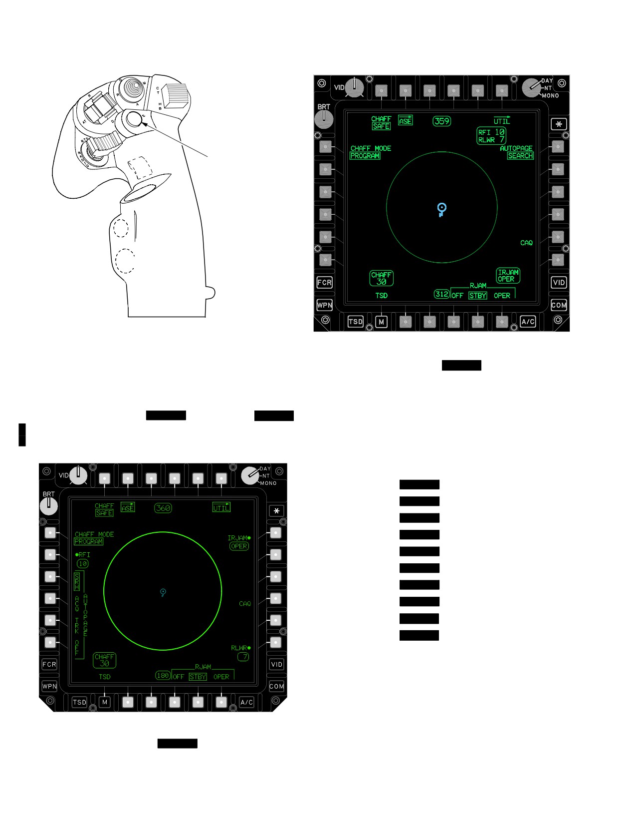
TM 1-1520-251-10
CHAFF
LBA−1971
LBA5172
Figure 4-99. Cyclic Grip-Chaff Dispense Button
Figure 4-100A.
[
BLK 2
ASE Page]
4.89 AIRCRAFT SURVIVABILITY EQUIPMENT (ASE)
PAGE
The ASE page contains the following unique buttons:
The ASE page (figs [
BLK 1
4-100] and [
BLK 2
• T1
CHAFF button
4-100A ] ) can be accessed from the MENU page, TSD
• T2
ASE button
UTIL page, or the WPN page.
•
T6
ASE UTIL button
• L1
CHAFF MODE button
• L2
[
BLK 1
RFI button]
• L3
[
BLK 1
AUTOPAGE SRH button]
• L4
[
BLK 1
AUTOPAGE ACQ button]
• L5
[
BLK 1
AUTOPAGE TRK button]
• L6
[
BLK 1
AUTOPAGE OFF button]
• R1
[
BLK 1
IRJAM button]
• R4
[
BLK 1
CAQ button]
• R6
[
BLK 1
RLWR button]
• R1
[
BLK 2
AUTOPAGE button]
• R5
[
BLK 2
CAQ button]
• B4
RJAM OFF button
• B5
RJAM STBY button
• B6
RJAM OPER button
4.89.1 CHAFF Button. The CHAFF button modes the
LBA0418
chaff dispense system between SAFE and ARM. Chaff
SAFE/ARM status is also displayed on the WPN and ASE
Figure
4-100.
[
BLK 1
ASE Page]
UTIL pages.
Use or disclosure of this information is subject to the restriction(s) on the title page of this document.
4-114
Change 3
TM 1-1520-251-10
4.89.2 ASE Button. The ASE button displays the ASE
4.89.11 CAQ Select Button. It is barriered when the
page. The ASE page presents RFI and RLWR threat in-
RFI is powered OFF or sight selected is FCR.
dications, as well as subsystem controls.
4.89.11A [
BLK 2
AUTOPAGE Button. The AUTO-
PAGE button is used to select the state or condition of an
4.89.3 ASE UTIL Button. The ASE UTIL button dis-
acquiring threat system which causes autopaging of
plays the ASE UTIL page and presents chaff program
threat warning information.] The available selections are:
controls and other utility controls.
• SEARCH
4.89.4 CHAFF MODE Button. The CHAFF MODE but-
• ACQUISITION
ton modes the chaff dispense system between PRO-
• TRACK
GRAM and MANUAL. The PROGRAM mode provides
the ability to dispense chaff cartridges according to a pre-
• OFF
determined program when the chaff dispense switch is ac-
4.89.12 [
BLK 1
RLWR Button. The RLWR button
tioned. The MANUAL mode will dispense one chaff car-
powers the RLWR ON or OFF. Powering the RLWR ON
tridge each time the chaff dispense switch is actioned.
enables up to seven detected RLWR threats to be dis-
played on the inside of the ASE footprint and in the status
4.89.5 [
BLK 1
RFI Button. The RFI button is only
window.]
presented when the FCR is powered ON. The RFI button
powers the RFI ON or OFF. Powering the RFI ON enables
4.89.13 RJAM OFF Button. The RJAM OFF button
up to ten detected RFI threats to be displayed on the out-
powers the Radar Jammer OFF.
side of the ASE footprint and in the status window. RFI
ON/OFF is also presented on the FCR UTIL page and
NOTE
WPN UTIL page.]
RJAM STBY and OPER are not present
when RJAM is OFF on the TSD and VIDEO
4.89.6 [
BLK 1
AUTOPAGE SRH Button. The AU-
pages.
TOPAGE SRH button sets the ASE Autopaging threshold
to search. ASE Autopage triggering occurs when a new
4.89.14 RJAM STBY Button. The RJAM STBY button
RLWR is detected in the search mode or a threat transi-
sets the Radar Jammer in the standby mode for warm-up
tions to a higher mode.]
period of 3 minutes. A deselected JAM button is pres-
ented on the TSD and VIDEO pages which can be used to
mode the RJAM between standby and operate. Selecting
4.89.7 [
BLK 1
AUTOPAGE ACQ Button. The AU-
the OFF button will interrupt the standby mode warm up
TOPAGE ACQ button sets the ASE Autopaging threshold
period.
to acquisition. ASE Autopage triggering occurs when a
new RLWR is detected in the acquisition mode or a threat
4.89.15 RJAM OPER Button. The RJAM OPER but-
transitions to a higher mode.]
ton sets the Radar Jammer in the operate mode. A se-
lected JAM button is presented on the TSD and VIDEO
pages which can be used to mode the RJAM between op-
4.89.8 [
BLK 1
AUTOPAGE TRK Button. The AU-
erate and standby. The system processor reverts the
TOPAGE TRK button sets the ASE Autopaging threshold
RJAM back to standby if operate is selected before the
to track. ASE Autopage triggering occurs when a new
warm up period.
RLWR threat is detected in the track mode or a threat tran-
sitions to a higher mode.]
4.89.15A [
BLK 2
Combined Emitter Status Win-
dow. The Combined Emitter status window displays
4.89.9 [
BLK 1
AUTOPAGE OFF Button. The AU-
the number of emitters reported from the RFI (up to 10)
TOPAGE OFF button sets the ASE Autopaging to OFF.]
and the number of emitters reported from the RWR or
RLWR (up to 7). The RFI, RWR or RLWR line is not dis-
played if the equipment is not installed or power on. If
4.89.10 [
BLK 1
IRJAM Button. The IRJAM button
none of these boxes are power on, then the status window
powers the IR Jammer ON or OFF. When powered on, the
is not displayed.]
IR Jammer will begin to function after a one minute warm-
up period. While in the warm up mode, the status window
4.89.16 CHAFF Status Window. The CHAFF status
will reflect WARM, then change to OPER when complete.
window displays the remaining number of chaff cartridges
If the IRJAM is not installed, the IRJAM button is not dis-
decremented by the system processor. It is also displayed
played.]
on the WPN page.
Use or disclosure of this information is subject to the restriction(s) on the title page of this document.
Change 2
4-115
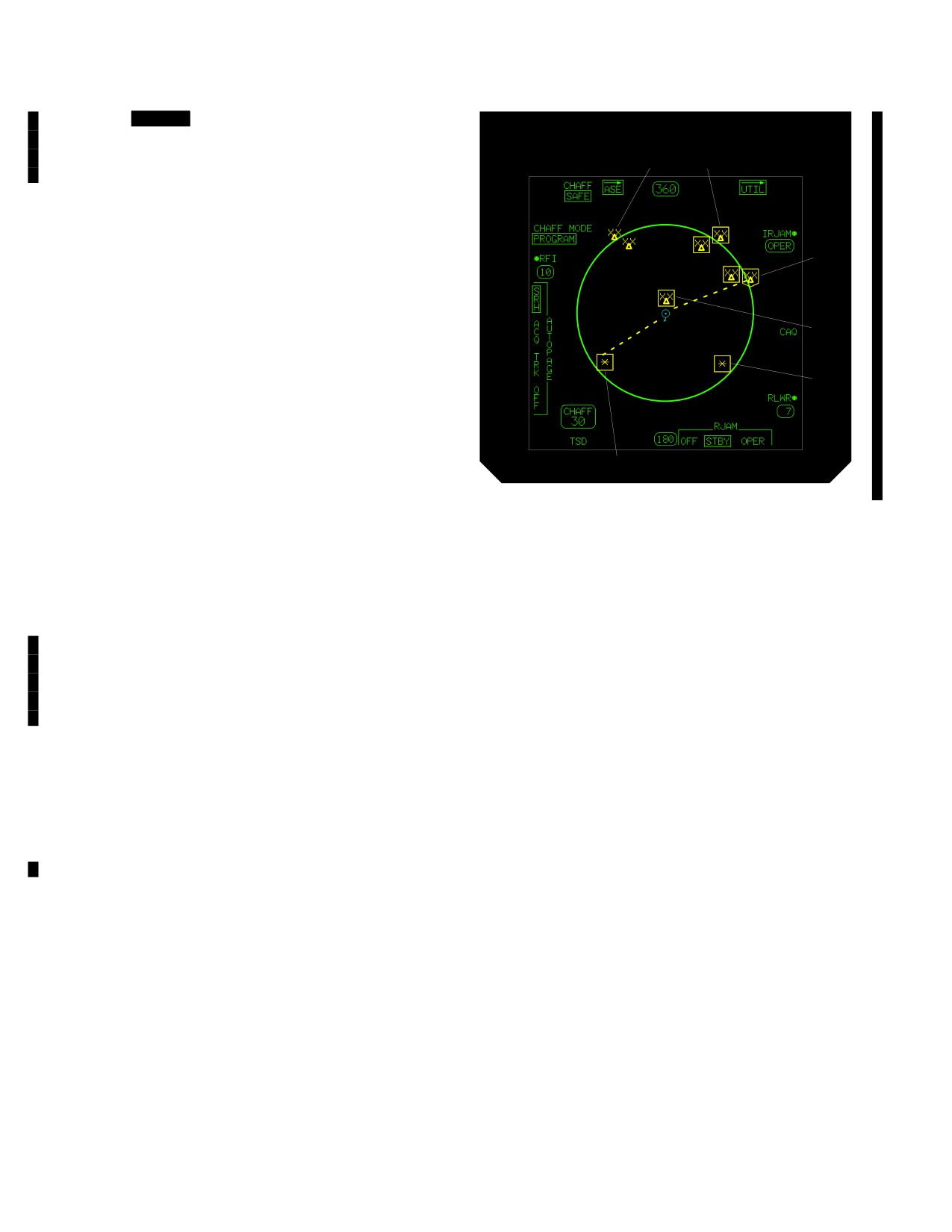
TM 1-1520-251-10
4.89.16A [
BLK 2
IRJAM Status Window. The IR-
JAM status window displays the state of the IR Jammer
(OPER or WARM). This status window is not displayed if
1
2
the IR Jammer is not installed or off.]
4.89.17 ASE Footprint. The ASE footprint is the circu-
lar area in the center of the ASE page. It is used to segre-
gate the RLWR and RFI threat indications. RLWR threat
3
indications appear on the inside of the ASE footprint and
RFI threat indications appear on the outside of the ASE
footprint. A rectangular threat footprint is also displayed
on the TSD page to segregate RLWR and RFI threat in-
5
dications.
4.89.18 RLWR or RFI Threat Indications. The RLWR/
6
RFI threat indications are displayed on the ASE footprint.
The symbology presented will identify the threats, show
the threat bearings relative to the ownship, and indicate
the mode of the threats (i.e. search, acquisition, track, or
7
launch). Friendly emitters are displayed in CYAN and en-
emy/gray emitters are displayed in YELLOW. Threat in-
LBA2486A
dications are also displayed on the TSD page.
Figure 4-101. ASE Symbology
4.89.19 Radar Jammer Icon. The Radar Jammer Icon
is displayed as a flashing lightening bolt in the center of
the Ownship Icon whenever the Radar Jammer is trans-
RWR and Other Than No.1 Emitter RFI Mode Icons.
mitting.
1. Search Mode. The search mode is identified by
4.89.20 Display Freeze Cue. The line through the A/C
the target symbol being unboxed.
Heading Status Window and the Next WPT Heading Sta-
tus Window indicates the ASE Symbology is not updating
2. Acquisition Mode. The acquisition mode is identi-
with respect to the aircraft. Reference Chapter 3, Section
fied by the target symbol being boxed.
III.
3. Tracking Mode. The tracking mode is identified
4.89.21 A/C Heading Map Freeze Cue. Reference
by the symbol being boxed and a dashed line between
Chapter 3, Section III.
Ownship and target symbol.
4.89.22 Ownship Icon. Reference Chapter 3, Section
4. Launch Mode. The launch mode is identified by
III.
the flashing box around the target symbol.
4.89.23 Deleted.
5. Uncorrelated RWR Detect. Identified by icon be-
ing oriented directly in front of ownship. Displays same as
4.89.24 Next WPT Heading Map Freeze Cue. Refer-
others (may or may not be boxed) but bearing unknown.
ence Chapter 3, Section III.
Laser Warning Receiver Mode Icons.
4.89.25 ASE Symbology. The symbology presented
(fig 4-101) will identify the threats, show the threat bear-
6. Ranging. Identified by icon being boxed.
ings relative to the ownship, and indicate the mode of the
threats (i.e. search, acquisition, track, or launch). Threat
mode icons are displayed in YELLOW. These icons will be
7. Designating. Identified by the icon being boxed
displayed on the ASE footprint of the ASE page and TSD
with dashed line between Ownship and target symbol.
page. RFI icons are displayed on the outside of the foot-
print and RLWR icons are displayed inside the footprint.
8. Beaming. Identified by the flashing box around
The FCR page only displays RFI icons (para.4.45.1).
the icon.
Use or disclosure of this information is subject to the restriction(s) on the title page of this document.
4-116
Change 2
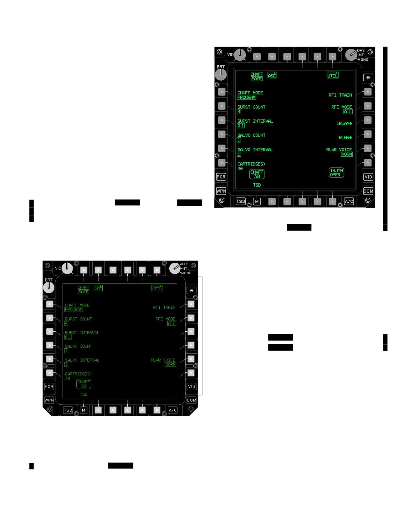
TM 1-1520-251-10
4.89.26 Load Maintenance Panel. Chaff inventory is
performed by the system processor and can be manually
updated by the ground crew via the load maintenance
panel or the air crew via the MPD. The ground crew enters
the CHAFF option from the display main menu via the
load maintenance panel key pad. After the ground crew
enters the number of loaded chaff cartridges (0-30) and
enter via the key pad, the load maintenance panel trans-
mits the new chaff count to the system processor repre-
senting the cartridge count via the load maintenance pan-
el serial link. The system processor monitors and updates
the display processor and load maintenance panel with
cartridge count status.
4.90 ASE UTIL PAGE
The ASE UTIL Page (figs [
BLK 1
4-102] and [
BLK 2
4-102A ] ) is as depicted below and is used to configure
LBA5173
the ASE Subsystem:
Figure 4-102A.
[
BLK 2
ASE UTIL Page]
The ASE UTIL page contains the following unique but-
tons:
• L2
BURST COUNT button
• L3
BURST INTERVAL button
• L4
SALVO COUNT button
• L5
SALVO INTERVAL button
• L6
CARTRIDGES button
• R1
RFI TRAIN button
• R2
RFI MODE button
• R3
[
BLK 2
IRJAM button]
• R4
[
BLK 2
RLWR button]
• R5
RLWR VOICE button
NOTE
BURST COUNT, BURST INTERVAL, SAL-
VO COUNT, and SALVO INTERVAL but-
tons are present if CHAFF MODE is set to
PROGRAM.
LBA0417
4.90.2 BURST COUNT Button. The BURST COUNT
button enables programming of 1, 2, 3, 4, 6, or 8 chaff car-
tridges to be fired per salvo.
4.90.3
BURST INTERVAL Button. The BURST IN-
TERVAL button enables programming of 0.1, 0.2, 0.3, or
Figure
4-102.
[
BLK 1
ASE UTIL Page]
0.4 tenths of seconds between chaff bursts.
Use or disclosure of this information is subject to the restriction(s) on the title page of this document.
Change 2
4-117
TM 1-1520-251-10
4.90.4 SALVO COUNT Button. The SALVO COUNT
4.90.10 RLWR VOICE Button. The RLWR VOICE but-
button enables programming of 1, 2, 4, 8, or CONTINU-
ton modes the RLWR system between NORM or TERSE
OUS salvos per activation of the Chaff Dispense switch.
voice messages.
4.90.5
SALVO INTERVAL Button. The SALVO IN-
4.91
DISPENSER KIT OPERATION
TERVAL button enables programming of 1, 2, 3, 4, 5, 8, or
RANDOM time intervals in seconds, between salvos.
RANDOM is actually a pseudo random sequence set at 3,
CAUTION
5, 2, and 4 seconds.
Operation is totally independent of air-
4.90.6
CARTRIDGES Button. The Chaff CAR-
craft ARM/SAFE power.
TRIDGES button provides a means to enter a number
from 0 to 30, indicating the number of cartridges loaded
1. CARTRIDGES - Set for number of chaff car-
into the M-141 Chaff Dispenser through the KU. This is an
tridges in payload module.
alternative to entering the data via the Load Maintenance
Panel (LMP).
2. CHAFF MODE - Program - Select BURST
4.90.7 RFI TRAIN Button. The RFI TRAIN button is
COUNT, BURST INTERVAL, SALVO COUNT,
only presented when the RFI is powered on. RFI TRAIN
and SALVO INTERVAL - As desired.
modes the RFI system to the training mode. RFI TRAIN is
also presented on the FCR UTIL page.
3. CHAFF - ARM.
4.90.8 RFI MODE Button. The RFI MODE button is
4. Chaff Dispense button - Press and release.
only presented when the RFI is powered on. RFI MODE
modes the RFI system to display ALL or HOSTILE
5. CHAFF - SAFE.
threats. RFI MODE is also presented on the FCR UTIL
page.
4.92
ASE OPERATIONAL CHECK
4.90.8 [
BLK 2
IRJAM Button. The IRJAM button
powers the IR Jammer ON or OFF. When powered on, the
1. WPN ASE page - Power ON ASE systems as
IR Jammer will begin to function after a one minute warm-
desired.
up period. While in the warm up mode, the status window
will reflect WARM, then change to OPER when complete.
2. DMS IBIT page - Perform IBITs and verify “NO
If the IRJAM is not installed, the IRJAM button is not dis-
FAULTS FOUND” for:
played.]
a. RJAM.
4.90.9
[
BLK 2
RLWR Button. The RLWR button
powers the RLWR ON or OFF. Powering the RLWR ON
b. RLWR.
enables up to seven detected RLWR threats to be dis-
played on the inside of the ASE footprint and in the status
window.]
3. UFD - Check WCA for advisories.
Use or disclosure of this information is subject to the restriction(s) on the title page of this document.
4-118
Change 3
TM 1-1520-251-10
CHAPTER 5
OPERATING LIMITS AND RESTRICTIONS
Section I. GENERAL
5.1 PURPOSE
See current Interim Statement of Airworthiness Qualifica-
tion (ISAQ) for additional limitations/restrictions.
This chapter identifies operating limits and restrictions
5.2.1 Exceeding Operational Limits. Any time an op-
that will be observed during ground and flight operations.
erational limit is exceeded, an appropriate entry shall be
made on DA Form 2408-13-1. Entry will state what limit or
limits were exceeded, range, time beyond limit and any
5.2 GENERAL
additional data that would aid maintenance personnel in
the maintenance action that may be required. The DMS
The operating limitations set forth in this chapter are the
provides engine performance evaluation and fault detec-
direct results of design analysis, test and operational ex-
tion.
periences. Normal, transient and maximum limits are dis-
played via the MPDs to the crew with corresponding digi-
5.2.2 Minimum Crew Requirements. The minimum
tal readouts, vertical scales, timers and color coding.
crew required to fly the helicopter is a pilot and a copilot. A
Compliance with restrictions and limits outlined in this
technical observer may be authorized to occupy the CPG
chapter will allow the pilot to safely perform the assigned
station during ground maintenance at the discretion of the
missions and to derive maximum utility from the aircraft.
commander.
Use or disclosure of this information is subject to the restriction(s) on the title page of this document.
5-1
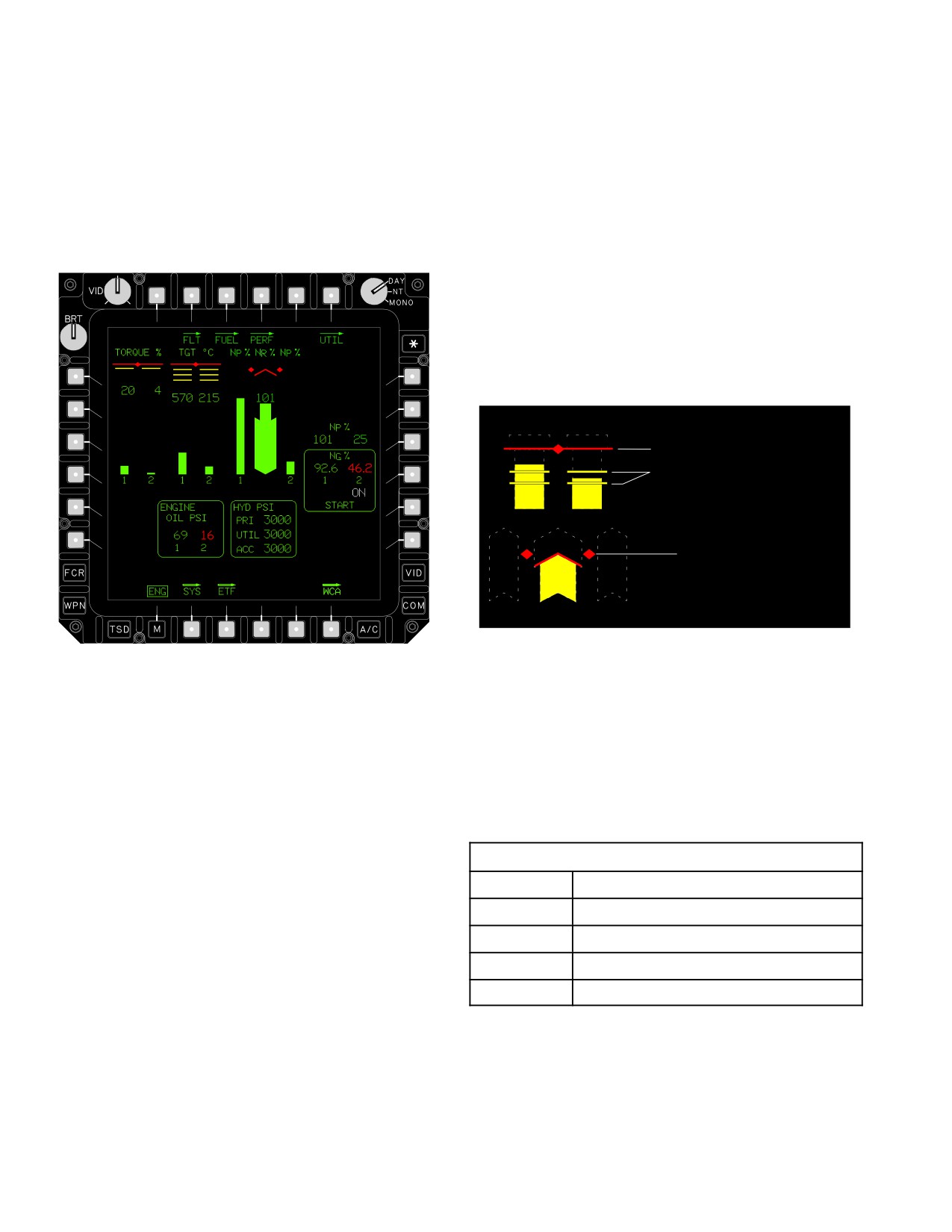
TM 1-1520-251-10
Section II. SYSTEM LIMITS
5.3 INSTRUMENT MARKINGS
• Wide: entire tape is RED; indicates the limit above
or below which continued operation is likely to
5.3.1 Instrument Marking Code. Operating limitations
cause damage or shorten component life.
and ranges are illustrated by graphic symbols and color
coding of systems instruments on the ENG page (fig 5-1).
Graphic symbols are displayed (fig 5-2) in conjunction
with each vertical tape to provide instrument limit mark-
ings:
• RED horizontal bar and diamond symbols indicate
the maximum operating limit.
• YELLOW horizontal bar indicates the beginning of
a sub - range cautionary operating range.
MAXIMUM LIMIT MARKING
SUBRANGE LIMIT MARKING
MAXIMUM LIMIT
MARKING (NR)
LBA3037
LBA−3036
Figure 5-2. Instrument Limit Marking Symbols
Figure 5-1. ENG Page Ground Format
5.3.2 Rotor Speed (NR) Limitations. Main rotor speed
Digital readouts are color coded according to normal
(NR %) (fig 5-3 ) is displayed as a vertical tape and a digi-
(GREEN), cautionary (YELLOW), maximum (RED) oper-
tal readout (within the tape) on the ENG page. The NR in-
ating ranges of the system. Readouts are displayed in
strument graphic is displayed in conjunction with the NP
WHITE when data is not in a valid range. Systems indica-
instrument of both engines. The following limits and their
tions displayed with a vertical tape incorporate color cod-
associated symbols apply to NR.
ing and shape coding (width of the tape) to delineate the
normal, cautionary, maximum operating ranges of the
LIMIT - NR (%) Digital Readout
system. Tapes are displayed in three different widths and
colors based on the current operating range:
110
Maximum (>110 RED)
• Narrow: entire tape is GREEN; indicates safe or
106 - 110
Transient operation (YELLOW)
normal range of operation.
106
High rotor warning annunciated
• Medium: entire tape is YELLOW; indicates range
95 - 105
Normal operation (GREEN)
when special attention should be given to opera-
0-94
Transient operation (RED)
tion.
Use or disclosure of this information is subject to the restriction(s) on the title page of this document.
5-2
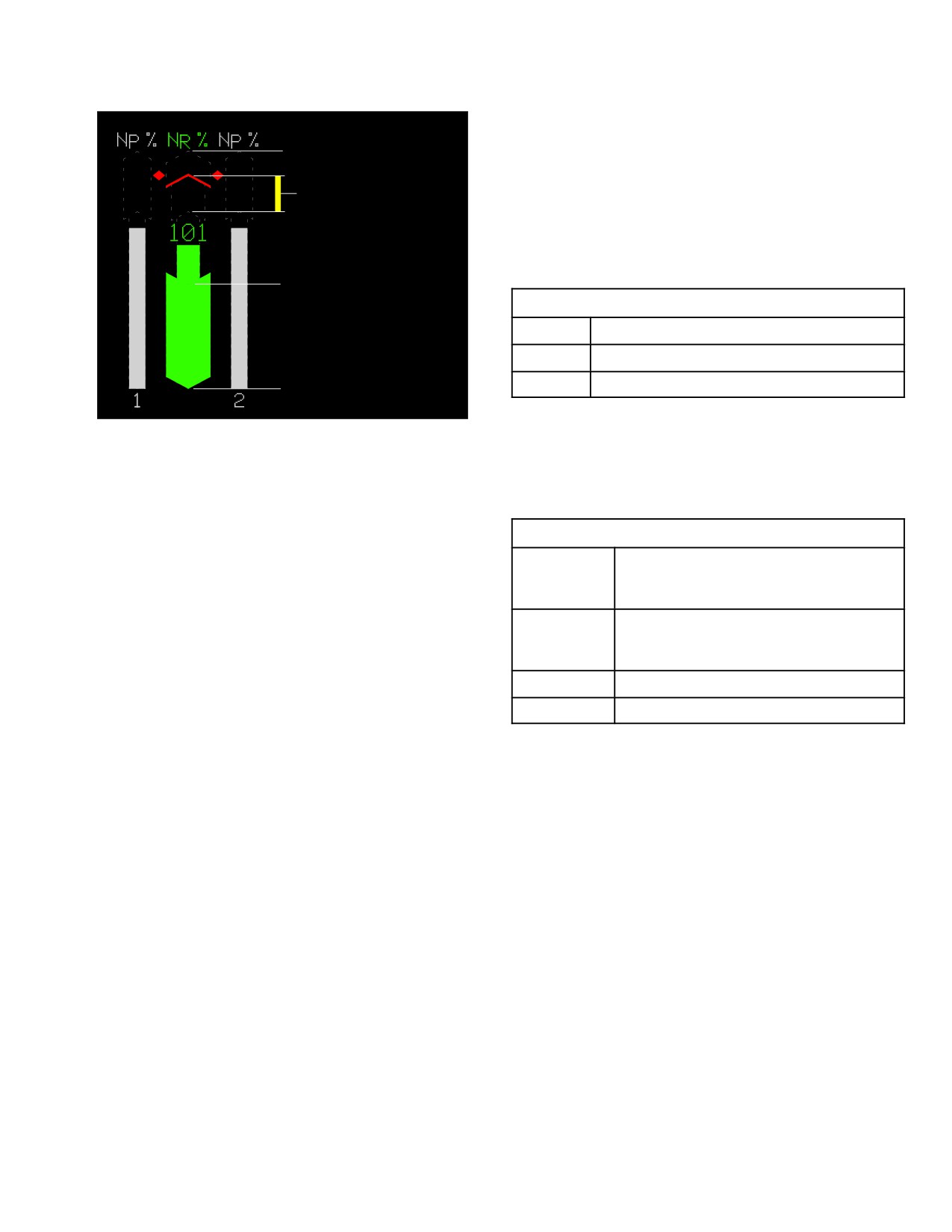
TM 1-1520-251-10
NOTE
120%
It is normal for oil pressure to be high during
first start when oil is cold. Oil pressure
110% MAXIMUM LIMIT
should return to normal after 5 minutes op-
106%110% TRANSIENT
eration at idle speed. During these 5 min-
105% MAXIMUM OF
utes, do not accelerate above ground idle
speed until oil pressure can be held at or be-
NORMAL OPERATING RANGE
low maximum limit throughout acceleration.
94% MINIMUM OF
LIMITS - ENGINE1 OR 2 OIL PRESSURE (PSI)
NORMAL OPERATING RANGE
120
Maximum (>120 RED w/box)
23 - 120
Normal operation (GREEN)
23
Minimum, PWR LVR at IDLE <23 RED
0%
5.3.4 Hydraulic Systems. Primary (PRI) utility (UTIL),
LBA3038
and accumulator (ACC) hydraulic (HYD) pressure (PSI)
are displayed as digital readouts on the ENG and aircraft
SYS pages. The limits for all hydraulic systems digital
readouts are as follows:
LIMITS - HYDRAULIC PRESSURE
Figure
5-3. NR Vertical Tapes
>3400
Transient operation permitted for 5 se-
conds (YELLOW). ( ≥ 5 seconds RED
w/box)
3310 - 3400
Transient - operation permitted for 5
5.3.3
Engine Lubrication System. Engine oil (EN-
minutes (YELLOW) ( ≥ 5 minutes RED
GINE OIL) pressure (PSI) is displayed as digital readouts
w/box)
on the ENG and aircraft SYS pages. Engine lubrication oil
2750 - 3300
Normal operation (GREEN)
pressure digital readout limitations during stabilized pow-
1260
Minimum (<1260 RED w/box)
er settings are as follows:
Use or disclosure of this information is subject to the restriction(s) on the title page of this document.
5-3
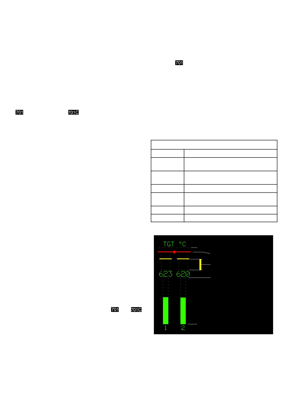
TM 1-1520-251-10
Section III. POWER LIMITS
5.4 ENGINE POWER LIMITATIONS
a.
701
Engine.
NOTE
The following limitations present absolute limitations for
the pneumatic engine starter and engine(s) power regard-
Each engine incorporates a steady state
less of the atmospheric conditions. For variation in power
TGT limiter control which limits engine op-
available with temperature and pressure altitude, refer to
eration according to the following indicated
the charts in the Performance Data Chapter (Chapter 7 for
TGT values:
and Chapter 7A for
engines).
Dual Engine: 860 +/ - 12 (848 - 872)° C
Single Engine: 917 +/ - 12 (905 - 929)° C
The limit value within these ranges can
5.4.1
Engine Starter Limitations. The pneumatic
change over a period time.
starter is capable of making the number of consecutive
start cycles listed below, when exposed to the environ-
LIMITS - 701 TGT (°C) DIGITAL READOUT
mental conditions specified, with an interval of at least 60
965
Maximum (> 965 RED)
seconds between the completion of one cycle and the be-
ginning of the next cycle. A starting cycle is the interval
920 - 965
Single engine transient, 12 second limit
(YELLOW)
from start initiation and acceleration of the output drive
shaft, from zero rpm, to starter dropout. The 60 second
865 - 919
Single engine contingency, 2.5 minute
delay between start attempts applies when the first at-
limit (YELLOW)
tempt is aborted for any reason and it applies regardless
869
Maximum during start
of the duration of the first attempt. If motoring is required
808 - 864
Intermediate rated power, 30 minute
for an emergency, the 60 second delay does not apply.
limit (YELLOW)
807
Maximum continuous power
a. Engine Starts At Ambient Temperatures of 61
0-807
Normal operation (GREEN)
°F (16 °C) and Below. Two consecutive start cycles
may be made, followed by a 3 minute rest period, followed
by two additional consecutive start cycles. A 30 minute
rest period is then required before any additional
starts.
999 °C
965 °C MAXIMUM LIMIT
b. Engine Starts At Ambient Temperatures Above
61 °F (16 °C). Two consecutive start cycles may be
808 °C 864 °C TRANSIENT
made. A 30 minute rest period is then required before any
RANGE (30 MINUTE)
additional starts.
807 °C MAXIMUM LIMIT
c. Dual Engine Starts. Dual engine starts are pro-
NORMAL OPERATING RANGE
hibited.
5.4.2 Engine Temperature Limitations (
and
engines). Engine Turbine Gas Temperature (TGT °C) is
displayed (figs 5-4, 5-5, 5-6, 5-7) as a vertical tape and a
0 °C
digital readout (within the tape) for each engine on the
ENG page. The configuration of the instrument graphic is
LBA3039
based upon the type engines installed and current mode
of operation, dual engine (DE) or single engine (SE). The
following limits and their associated symbols apply to TGT
limitations.
Figure
5-4. DE, 701 TGT Vertical Tapes
Use or disclosure of this information is subject to the restriction(s) on the title page of this document.
5-4
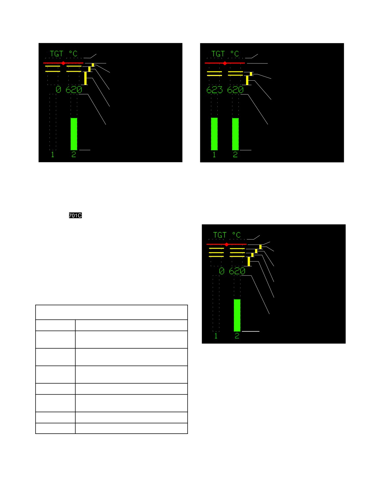
TM 1-1520-251-10
999° C
999° C
965° C MAXIMUM LIMIT
949° C MAXIMUM LIMIT
920 965 ° C TRANSIENT
RANGE (12 SECOND LIMIT)
871 878° C TRANSIENT
RANGE (10 MINUTE LIMIT)
865 919° C TRANSIENT
RANGE (2.5 MINUTE LIMIT)
811 870° C TRANSIENT
808 864° C TRANSIENT
RANGE (30 MINUTE LIMIT)
RANGE (30 MINUTE LIMIT)
807° C MAXIMUM OF
810° C MAXIMUM OF
NORMAL OPERATING RANGE
NORMAL OPERATING RANGE
°
0
C
0° C
LBA3040
LBA3041
Figure 5-5. SE, 701 TGT Vertical Tapes
Figure
5-6.
DE, 701C TGT Vertical Tapes
b.
701C
Engine.
NOTE
999° C
Each engine incorporates a steady state
949° C MAXIMUM LIMIT
TGT limiter control which limits engine op-
eration according to the following indicated
897 949° C TRANSIENT
RANGE (12 SECOND LIMIT)
TGT values:
Dual Engine: 867 +/ - 12 (855 - 879)° C
879 896° C TRANSIENT
RANGE (2.5 MINUTE LIMIT)
Single Engine: 896 +/ - 12 (884 - 908)° C
The limit value within these ranges can
871 878° C TRANSIENT
RANGE (10 MINUTE LIMIT)
change over a period time.
811 870° C TRANSIENT
RANGE (30 MINUTE LIMIT)
LIMITS - 701C TGT (°C) DIGITAL READOUT
810° C MAXIMUM OF
NORMAL OPERATING RANGE
949
Maximum (>949 RED)
0° C
897 - 949
Single engine transient, 12 second limit
(YELLOW)
LBA3042
879 - 896
Single engine contingency, 2.5 minute
limit (YELLOW)
Figure
5-7.
SE, 701C TGT Vertical Tapes
871 - 878
Intermediate rated power, 10 minute
limit (YELLOW)
851
Maximum during start
5.4.3
Engine Power Turbine Speed, (NP). Engine
811 - 870
Intermediate rated power, 30 minute
power turbine speed (NP %) is displayed (fig 5-8 ) as a
limit (YELLOW)
vertical tape and a digital readout for each engine on the
ENG page. The NP digital readouts are displayed sepa-
810
Maximum continuous power
rately from the vertical tapes. The following limits and their
0-810
Normal operation (GREEN)
associated symbols apply to engine NP:
Use or disclosure of this information is subject to the restriction(s) on the title page of this document.
5-5
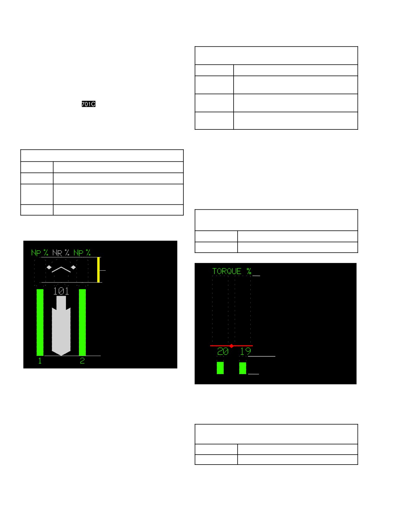
TM 1-1520-251-10
NOTE
LIMITS - ENGINE1 OR 2 NG (%) DIGITAL
READOUT
• It is not abnormal to observe a NP1 and
105.1
Maximum (>105.1 RED)
NP2 speed split during autorotation de-
scent when the engines are fully de-
102.3 -
Transient 12 second limit (YELLOW)
coupled from the transmission. A speed
105.1
increase from 101% reference to 103% is
63.1 -
Normal operation (GREEN)
possible for
only.
102.2
63
Minimum engine out warning annun-
• Maximum NP vertical tape indication is
ciated (<63.0 RED w/box).
120 %.
5.4.5 Engine Torque. Engine torque (TORQUE %) is
displayed (figs 5-9 thru 5-12) as a vertical tape and a digi-
LIMITS - ENGINE1 OR 2 NP (%) Digital Readouts
tal readout for each engine on the ENG page. The config-
uration of the instrument graphic is based upon main rotor
121
Maximum (>121 RED w/box).
speed (NR) and the current mode of operation, dual en-
115
Engine overspeed annunciated
gine (DE) or single engine (SE). The following limits and
their associated symbols apply to engine torque limita-
106 - 121
Transient operation, 12 seconds
tions:
(YELLOW, w/box at 107).
0-105
Normal operation (GREEN)
LIMITS - TORQUE (%) DIGITAL READOUT
WITH NR LESS THAN 50%
30
Maximum (>30 RED)
0-30
Normal operation (GREEN).
120%
106%120% TRANSIENT
130%
105% MAXIMUM OF
NORMAL OPERATING RANGE
0%
30% MAXIMUM,
DO NOT EXCEED WITH LESS
THAN 50% NR
LBA3043A
0%
LBA2618
Figure 5-8. NP Vertical Tapes
Figure 5-9. Torque Vertical Tapes, NR below 50%
LIMITS - TORQUE (%) DIGITAL READOUT
5.4.4
Engine Gas Generator (NG) Limitations. En-
WITH NR LESS THAN 90%
gine gas generator speed (NG %) is displayed as a digital
70
Maximum (>70 RED)
readout for each engine on the ENG page. The following
0-70
Normal operation (GREEN).
limits apply to engine NG:
Use or disclosure of this information is subject to the restriction(s) on the title page of this document.
5-6
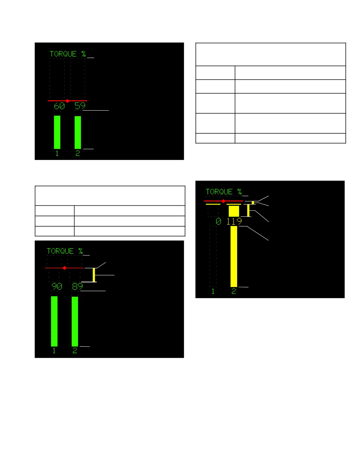
TM 1-1520-251-10
LIMITS - TORQUE (%) DIGITAL READOUT
130%
SINGLE ENGINE
125
Maximum (>125 RED)
123 - 125
Transient 6 second limit (YELLOW).
111 - 122
Single engine contingency, 2.5 minute
limit (YELLOW).
70% MAXIMUM,
DO NOT EXCEED WITH LESS
110
Single engine maximum continuous
THAN 90% NR
power (GREEN).
0-110
Normal operation (GREEN).
0%
LBA2619
Figure 5-10. Torque Vertical Tapes, NR 50% - 90%
LIMITS - TORQUE (%) DIGITAL READOUT
130%
125% MAXIMUM LIMIT
DUAL ENGINE
123%125% TRANSIENT
115
Maximum ( >115 RED)
RANGE (6 SECOND LIMIT)
101 - 115
Transient 6 second limit (YELLOW).
111%122%
RANG
E (2.5 MINUTE LIMIT)
0-100
Normal operation (GREEN).
110% MAXIMUM
NORMAL OPERATING RANGE
130%
115% MAXIMUM
LIMIT
101%115%
RANG
E (6 SECOND LIMIT)
0%
100% MAXIMUM OF
NORMAL OPERATING RANGE
LBA2621
0%
Figure 5-12. Torque Vertical Tapes, SE
LBA2620
Figure 5-11. Torque Vertical Tapes, DE
Use or disclosure of this information is subject to the restriction(s) on the title page of this document.
5-7
TM 1-1520-251-10
5.5 AUXILIARY POWER UNIT (APU) OPERATING
CAUTION
LIMITS
Do not operate the APU for more than 5
minutes at a main transmission oil tem-
CAUTION
perature of 120 - 130° C. Shut down APU
to prevent damaging accessory gearbox
components.
Avoid prolonged operation at 94% - 96%
NR with the APU running. The APU clutch
5.5.2 Extended APU Ground Operations. During pro-
will oscillate from engaged to disen-
longed ground operations greater than 30 minutes, ob-
gaged. This creates high loads on the
serve XMSN TEMP 1 and XMSN TEMP 2 on the SYS
clutch and shall be avoided.
page. If the temperatures exceed 130° C (266° F) the
APU shall be shutdown and the transmission fluid allowed
to cool for 30 minutes prior to resuming APU ground op-
5.5.1
APU Operating Limitations. APU operation is
erations; or transmission fluid may be cooled by operating
prohibited during normal flight. After a fault or aborted
an engine with rotor turning. There is no requirement to
start, wait 30 seconds after compressor has stopped be-
remove transmission side panels during extended APU
fore attempting another start. After 2 consecutive start at-
ground operations. However, the transmission fluid will
tempts, wait 20 minutes before third start attempt. No
not get as hot under high ambient temperature conditions
more than 3 start attempts are permitted in one hour.
if the side panels are removed.
Use or disclosure of this information is subject to the restriction(s) on the title page of this document.
5-8
TM 1-1520-251-10
Section IV. LOADING LIMITS
5.6 CENTER OF GRAVITY LIMITS
5.7 WEIGHT LIMITATIONS
Center of gravity limits for the helicopter to which this
The aircraft maximum gross weight is 20,260 pounds, ex-
manual applies and instructions for computation of center
cept for non - tactical ferry flights, which may not exceed
of the gravity are contained in Chapter 6.
23,000 pounds.
Section V. AIRSPEED LIMITS
5.8 AIRSPEED OPERATING LIMITS
5.8.6 Maximum Airspeed with Symmetrically Loaded
External Fuel Tanks (2 or 4) Installed. Maximum air-
See figure 5-13 to determine the Never Exceed Velocity
speed with symmetrically loaded external fuel tanks (2 or
(VNE) as a function of weight, altitude and temperature.
4) installed is 130 KTAS.
Additional airspeed limits listed below.
5.8.7 Maximum Airspeed for Stores Jettison. Jetti-
5.8.1
Airspeed Limits For Autorotation. Maximum
son of external armament stores is not authorized except
airspeed for autorotation is 145 KTAS.
for emergency conditions and then only from unacceler-
ated flight during:
5.8.2
Airspeed Limits With One Engine Inoperati-
ve. Maximum airspeed with one engine inoperative is
a. Maximum airspeed for stores jettison is 130 KTAS.
the greater of:
b. Hover to 45 KTAS (minimize side slip, if possible).
a.
67% of VNE determined from figure 5-13 using the
GROSS WEIGHT line.
c.
45 to 130 KTAS (ball centered, if possible).
b. The speed for minimum power determined from
the Chapter 7
or Chapter 7A
cruise charts using
5.8.8
Maximum Airspeed for External Tanks Jetti-
the MAX END/MAX R/C lines.
son. Jettison of external fuel tanks is not authorized ex-
cept for emergency conditions and then only from air-
5.8.3 Maximum Airspeeds During Manual Stabilator
speeds less than 100 KTAS. Jettison from level flight if
Operations. Maximum airspeeds are based on stabila-
possible, and if not, jettison at an airspeed which mini-
tor position. The stabilator position and nominal airspeed
mizes the rate of descent at the time of jettison.
restrictions are displayed on the FLT page, FLT SET
page, as well as the SYS page, as described in paragraph
5.8.9 Airspeed Operating Limits Chart. Referring to
2.68.
figure 5-13, sheet 1, note that a FAT scale and pressure
altitude scale are provided in the upper grid and a weight
5.8.4
Maximum Rearward/Sideward Flight
scale and true airspeed scale on the lower grid. Using the
Speed. Maximum rearward/sideward flight speed is 45
observed FAT and altitude obtained from the aircraft in-
KTAS for all gross weights.
struments and the calculated aircraft weight, enter the
chart as directed in the chart example. Determine maxi-
5.8.5
Maximum Airspeed for Searchlight Exten-
mum true airspeed at the left side of the lower grid. To de-
sion. The searchlight is designed for operation (extend/
termine the maximum indicated airspeed, refer to figure
retract/rotate) at speeds up to 90 knots. However, as long
5-13, sheet 2 and enter as directed in the chart example
as operation is not attempted, the lighthead can be left in
with the KTAS and density altitude determined from figure
any extended position at speeds up to 200 knots.
5-13, sheet 1.
Use or disclosure of this information is subject to the restriction(s) on the title page of this document.
5-9
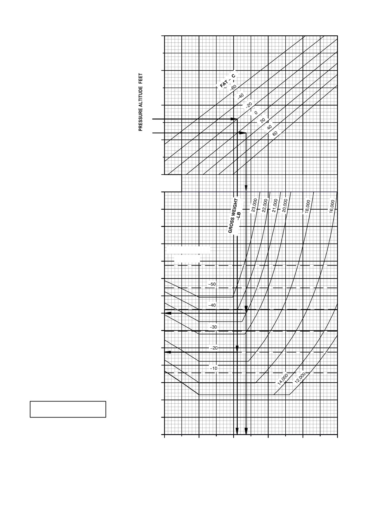
TM 1-1520-251-10
20000
AIRSPEED OPERATING LIMITS
101% ROTOR RPM
LEVEL FLIGHT
15000
°
EXAMPLE 1
10000
WANTED
MAXIMUM ALLOWED TRUE AIRSPEED
AND DENSITY ALTITUDE
KNOWN
PRESSURE ALTITUDE = 6000 FEET
5000
FAT = 10°C
GROSS WEIGHT = 21,000 POUNDS
METHOD
ENTER AT 6000 FEET
PRESSURE ALTITUDE
MOVE RIGHT TO FAT = 10°C
0
MOVE DOWN TO 21,000 POUND
GROSS WEIGHT OR MACH LIMIT
FAT, WHICHEVER IS ENCOUNTERED
FIRST. MOVE LEFT AT 21,000 LB LINE
80
AND READ TRUE
AIRSPEED = 150 KNOTS
MOVE DOWN, READ DENSITY
90
ALTITUDE = 6800 FEET
100
EXAMPLE 2
WANTED
110
MAXIMUM ALLOWED TRUE AIRSPEED
MACH NO. LIMITS
AND DENSITY ALTITUDE
KNOWN
120
FAT: 60°
PRESSURE ALTITUDE = 8000 FEET
FAT = 20°C
GROSS WEIGHT = 18,000 POUNDS
130
METHOD
ENTER AT 8000 FEET
140
PRESSURE ALTITUDE
MOVE RIGHT TO FAT = 20°C
MOVE DOWN TO 18,000 POUND
150
GROSS WEIGHT OR MACH LIMIT
FAT, IN THIS CASE, THE MACH
LIMIT FAT LINE IS ENCOUNTERED
FIRST. MOVE LEFT AT 20°C LINE
160
AND READ TRUE AIRSPEED = 172 KNOTS
MOVE DOWN, READ DENSITY
ALTITUDE = 5500 FEET
170
180
190
200
AIRSPEED
OPERATING LIMITS AH64D
210
220
5000
0
5000
10000
15000
20000
DATA BASIS:
DERIVED FROM FLIGHT TEST
DENSITY ALTITUDE ~ FEET
LBA01891
Figure
5-13.
Airspeed Operating Limits Chart (Sheet 1 of 2)
Use or disclosure of this information is subject to the restriction(s) on the title page of this document.
5-10
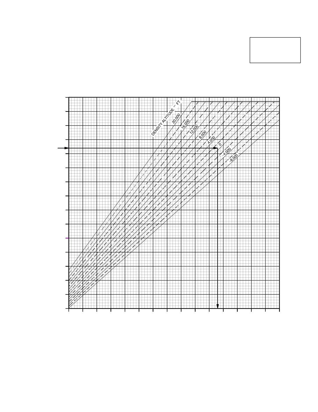
TM 1-1520-251-10
AIRSPEED CONVERSION
AIRSPEED
EXAMPLE
CONVERSION
AH−64D
ON SHEET 2 ENTER AT
164 KNOTS TRUE AIRSPEED
AND MOVE TO RIGHT TO 1500
FEET DENSITY ALTITUDE.
MOVE DOWN, READ INDICATED
AIRSPEED = 156 KNOTS.
NOTE: DASHED LINES ON CHART REPRESENT THE NEXT 2000 FT INCREMENT OF D.A. (POSITIVE AND NEGATIVE)
200
190
180
170
160
150
140
130
120
110
100
90
80
70
60
50
50
60
70
80
90
100
110
120
130
140
150
160
170
180
190
200
INDICATED AIRSPEED (PILOT’S GAUGE) ~ KNOTS
DATA BASIS: DERIVED FROM FLIGHT TEST
LBA01892
Figure 5-13. Airspeed Operating Limits Chart (Sheet 2 of 2)
Use or disclosure of this information is subject to the restriction(s) on the title page of this document.
5-11
TM 1-1520-251-10
Section VI. MANEUVERING LIMITS
5.9 MANEUVERING LIMITS
5.9.4 External Tanks. With external fuel tanks (2 or 4)
containing fuel, symmetrically installed, the following re-
For normal load factors, refer to figure 5-14. Intentional
strictions apply:
maneuvers beyond attitudes ± 30° in pitch or ± 60° in roll
are prohibited.
a. Normal load factor of 2 Gs shall not be exceeded.
5.9.1
Prevent Excessive Tail Rotor Loads. Avoid
b. Maneuvers are limited to those required to takeoff,
large pedal step inputs in arresting right hovering/low
climb to optimum altitude, heading/course corrections, ob-
speed yawing turns greater than 60°/second. This is to
stacle avoidance, descend and land.
prevent excessive tail rotor drive system loads.
c.
230 gal external fuel tanks shall be in the flight stow
5.9.2
Flight with Canopy Enclosure Open. Flight,
position (4° nose-up) with respect to the waterline (WL).
hovering flight and air taxiing with the canopy enclosure
open are prohibited, except for smoke/fume elimination.
d. Rapid and step-shaped pedal inputs in excess of
1/2 in. shall be avoided.
5.9.3 Landing Limits. Do not complete a landing on
terrain which produces a pitch attitude change from a hov-
e. Operation of the aircraft with the 230 - gallon Ex-
er greater than 7° nose up or 12° nose down; or a roll atti-
tended Range Fuel System (ERFS) is prohibited during
tude greater than 10°.
operations where hostile fire is highly probable.
Section VII. ENVIRONMENTAL RESTRICTIONS
5.10 ENVIRONMENTAL RESTRICTIONS
5.10.3
Flight In Instrument Meteorological Condi-
tions. The aircraft is not qualified for IMC flight. The
5.10.1 Flight into Turbulence. Flight into known or
back - up flight instruments are required to be installed and
forecast extreme turbulence or into known severe turbu-
operational for all flights.
lence is prohibited.
5.10.2 Flight In Icing Conditions. Intentional flights
into moderate icing conditions are prohibited. Flight into
5.10.4
Rotor Limitations
- Start and Stop Lim-
known or forecast trace or light icing conditions is autho-
rized and not considered a hazard unless the condition is
its. Maximum wind velocity for rotor start or stop is 45
encountered for an extended period (over one hour).
knots.
Section VIII. OTHER LIMITS
5.11 WING STORES CONFIGURATION
5.12 USE OF FORCE TRIM.
For authorized wing stores configurations refer to Chapter
Force trim will not be selected OFF except in a failed or
7
or 7A
, figure 7-26
or 7A-28
partial failed mode.
Use or disclosure of this information is subject to the restriction(s) on the title page of this document.
5-12
Change 4
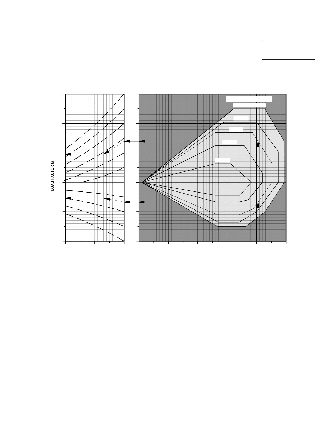
TM 1-1520-251-10
FLIGHT ENVELOPE
FLIGHT ENVELOPE
AH64D
4
4
GROSS WEIGHT ~ LB
14,660 OR LESS
16,530
3
3
18,280
20,260
2
2
23,000
1
1
0
0
1
1
20000
10000
0
50
0
50
100
150
200
DENSITY ALTITUDE ~ FT
TRUE AIRSPEED ~ KNOTS
EXAMPLE
WANTED
MAXIMUM AND MINIMUM LOAD FACTOR
KNOWN
GROSS WEIGHT = 18,280 POUNDS
DENSITY ALTITUDE = 7000 FEET
AIRSPEED = 152.5 KTAS
METHOD
ENTER AT V = 152.5 KTAS. MOVE UP TO UPPER AND LOWER ENVELOPE BOUNDARIES FOR
GROSS WEIGHT = 18,280 POUNDS.
MOVE LEFT TO DENSITY ALTITUDE OF ZERO FEET.
SLIDE TO LEFT ALONG DASHED LINES TO 7000 FEET DENSITY ALTITUDE.
MOVE LEFT TO LOAD FACTOR SCALE, READ MAX G = 1.96, MIN G = 0.46.
DATA BASIS: DERIVED FROM FLIGHT TEST
LBA0191
Figure 5-14. Flight Envelope Chart
Use or disclosure of this information is subject to the restriction(s) on the title page of this document.
5-13/(5-14 blank)
TM 1-1520-251-10
CHAPTER 6
WEIGHT/BALANCE AND LOADING
Section I.
GENERAL
6.1 INTRODUCTION
b. Pilot Crew Station. The pilot station extends
from fuselage station 115.0 to station 168.0. The pilot
This chapter provides information required for helicopter
nominal centroid is at fuselage station 143.3, but the seat
loading and computing weight and balance.
can be adjusted so the pilot centroid can vary from fuse-
lage station 142.8 to 143.8. This produces a small mo-
6.1.1 Extent Of Coverage. This chapter contains suffi-
ment variation and should be ignored.
cient instructions and data so that an aviator, knowing the
basic weight and moment of the helicopter, can compute
NOTE
any combination of weight and balance using the pre-
When loading these two bays, check for ex-
scribed Army charts and forms.
ceeding the aft CG limit.
6.1.2 Helicopter Class. Army AH-64D Apache helicop-
c. Left Aft Equipment Storage Bay. The aft stor-
ter is in Class 2. Additional directives governing weight
age bay is on the left side from fuselage station 280.0 to
and balance of Class 2 aircraft forms and records are con-
station 310.0 and can be loaded to 15 pounds per square
tained in AR
95-1, DA PAM
738-751 and TM
foot with a capacity of 60 pounds. The floor area is
55-1500-342-23.
approximately 4.2 square feet and the volume is approxi-
mately 12.1 cubic feet. Floor tiedown fittings are in place
6.1.3
Helicopter Bays and Stations. The helicopter
to accommodate the flyaway kit.
has many bays; most of them contain electronic or other
equipment. Figure 6-1 shows the general location of the
major bays and equipment. The boundaries of all bays
d. Survival Equipment Stowage Bay. The survival
and a listing of the equipment in each bay are provided in
equipment stowage bay is reached from either side. From
the helicopter records Chart A - Basic Weight Checklist,
fuselage station 310.0 to station 340.0, it can be loaded to
DD form 365-1. The bays of primary concern to pilot,
15 pounds per square foot with a capacity of 100 pounds.
when loading, are the crew stations, left aft storage bay,
A single concentrated load of 45 pounds with a load densi-
survival kit bay and left and right flyaway kit bays. These
ty of 45 pounds per square foot may be carried. The floor
bays may contain personal items or extra equipment not
area is approximately 7.8 square feet and the volume is
accounted for in the basic weight (para 6.2.1). Any addi-
approximately 21.4 cubic feet. Floor tiedown fittings are in
tional items must be entered on the Weight and Balance
place to accommodate the survival kit.
Form F (DD365-4).
e. Flyaway Storage Bays. The Flyaway Storage
a. CPG Crew Station. The CPG station extends
Bays are located on the left and right sides of the aircraft
from fuselage station 35.5 to station 115.0. The CPG nom-
from fuselage stations 155.0 to 189.0. The bays have a
inal centroid is at fuselage station 82.2, but the seat can
load capacity of 33.5 pounds per bay. The floor area is
be adjusted so the CPG centroid can vary from fuselage
approximately 2 square feet with a volume of 3.5 cubic
station 81.9 to 82.8. This produces a small moment varia-
feet per bay. There are no tie down fittings in the bays. The
tion and should be ignored.
bays are capable of removal from the aircraft.
Use or disclosure of this information is subject to the restriction(s) on the title page of this document.
6-1
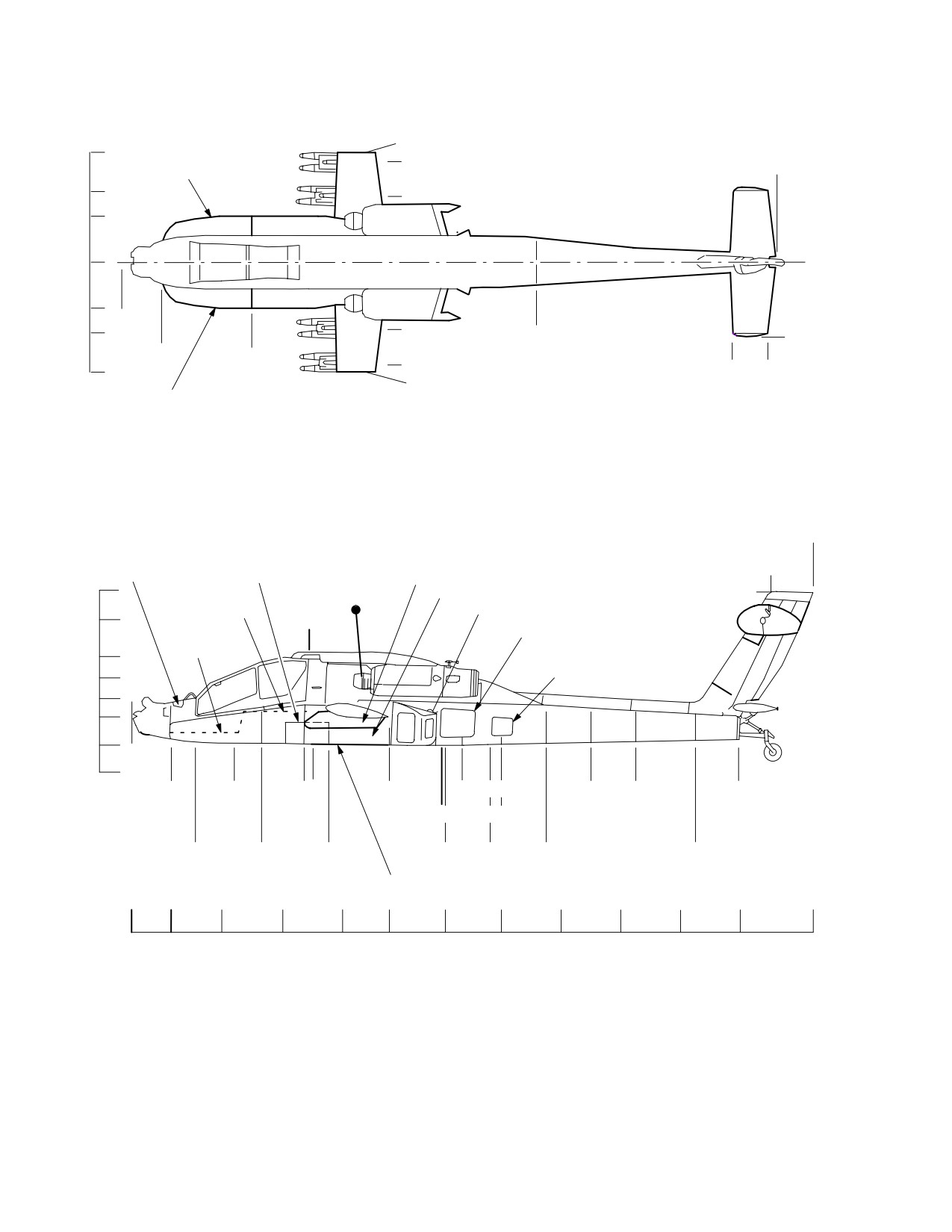
TM 1-1520-251-10
BL
BL 98.00
98.0
BL 93.00
FS 584.69
RIGHT EFAB
63.0
BL 63.00
41.0
0.0
BL 41.07
41.0
FS 0.00
63.0
BL 63.00
FS 370.00
BL 66.87
FS 35.50
FS
116.00
BL 93.00
FS 544.69
98.0
FS 576.54
BL 98.00
LEFT EFAB
PYLON FWD LUG STATION
ALL DIMENSIONS ARE IN INCHES
INBOARD = 184.4
BL BUTT LINE
OUTBOARD = 184.5
CL CENTERLINE
FS FUSELAGE
FS 596.18
NOSE ELECTRONICS
L/R FLYAWAY
PYLONS
KIT BAYS
FS 559.95
WL
BAY
199.0
ROTOR CL
AMMO BAY
242.2
WL242.2
PILOTS FLOOR
AFT FUEL TANK
215.9
FS 158.66
LEFT AFT EQUIPMENT STORAGE BAY
CPG FLOOR
183.0
SURVIVAL EQUIPMENT
STOWAGE BAY
164.0
FS 0.00
145.5
129.2
104.0
79.9
FS 35.50
FS 91.70
FS 154.30
FS 230.00
(FS 295.00)
FS 409.90
FS 450.00
FS 547.15
FS 166
FS 276.73
(FS 330.00)
FS 57.50
FS
FS 176.00
FS 280.00
FS 320.00 FS 370.00
FS 503.20
115.00
FWD FUEL TANK
FS
0.0
35.5
80.5
135.0
188.3
230.0
280.0
330.0
383.3
436.5
489.9
547.1
596.1
LBA0111
Figure 6-1. Station Diagram
Use or disclosure of this information is subject to the restriction(s) on the title page of this document.
6-2
TM 1-1520-251-10
Section II. WEIGHT AND BALANCE
6.2 WEIGHT AND BALANCE
b. Arm. For balance purposes, the term Arm is the
horizontal distance (in inches) from the reference datum
to the center of gravity of a given item. For special cases,
This section contains information needed to compute the
Arm can be determined from Figure 6-1. For the AH-64D
weight and balance for an individual helicopter by using
Apache helicopter, Arm and Fuselage Station (FS) are the
the prescribed standard charts and forms.
same.
6.2.1 Weight Definitions. The three major terms used
when defining helicopter weight: basic weight, operating
NOTE
weight and gross weight are described in the following
Throughout this chapter, moment/100 fig-
paragraphs.
ures have been rounded off to the nearest
whole number. When moments from other
NOTE
sources are being used, they must be di-
The basic weight of the helicopter will vary
vided by 100 and rounded off.
with mission requirements and structural
modifications such as addition or removal of
c. Moment. Moment is the weight of an item multi-
Longbow kit, wing pylons, peculiar kits,
plied by its Arm. For the AH-64D Apache helicopter, mo-
30mm gun, turret, ammo handling system,
ment divided by 100 (moment/100) is used to simplify cal-
etc. A continuing record of an individual heli-
culations by reducing the number of digits.
copter’s basic weight is maintained on Chart
C - Basic Weight and Balance Record, DD
d. Average Arm. Average Arm is the Arm obtained
Form 365-3.
by adding the weights and the moments of a number of
items and dividing the total moment by the total weight.
a. Basic Weight. The normal basic weight of this
helicopter includes wing pylons, all fixed operating equip-
e. Basic Moment. Basic moment is the sum of the
ment, 30mm gun, all oil and trapped fuel. It is only neces-
moments of all items making up the basic weight with re-
sary to add the variables or expendables to these items
spect to the helicopter reference datum.
for the missions. Basic weight can be entered into the
DTC via the AMPS and then loaded into the aircraft sys-
tem via the DTU.
f. Center of Gravity (CG). CG is the point about
which the helicopter would balance if suspended. Dis-
b. Operating Weight. The operating weight of the
tance from the reference datum is found by dividing the
helicopter is the basic weight plus those variables which
total moment by the gross weight of the helicopter.
remain substantially constant for a particular mission.
These items include crew, baggage, rocket launchers,
g. CG Limits. The CG limits are the extremes of
Hellfire launchers, any emergency or extra equipment that
movement to which the helicopter CG can travel without
may be required.
endangering controllability or structural integrity. The CG
of the loaded helicopter must remain within these limits at
c. Gross Weight. The gross weight is the total
takeoff, throughout flight and during landing. The forward
weight of the helicopter and its contents.
and aft CG limits are displayed on the PERF page (para
7.2.8
or 7A.2.8
. The actual CG will be displayed
6.2.2
Balance Definitions. The seven major terms
under CG and a vertical bar will move between the limits
used when defining helicopter balance: reference datum,
in direct proportion to the actual CG.
arm, moment, average arm, basic moment, center of
gravity (CG) and CG limits are described in the following
6.2.3 Chart C - Basic Weight and Balance Record, DD
paragraphs.
Form 365-3. Chart C is a continuous history of the basic
weight and moment resulting from structural and equip-
a. Reference Datum. The reference datum is an
ment changes in service. At all times, the last weight and
imaginary vertical plane from which all horizontal dis-
moment/100 entries are considered the current weight
tances are measured (in inches) for balance purposes.
and balance status of the basic helicopter.
Use or disclosure of this information is subject to the restriction(s) on the title page of this document.
6-3
TM 1-1520-251-10
6.2.4 Loading Data. The loading data in this chapter is
6.2.6 CG Management. This paragraph contains fuel
intended to provide information necessary to work loading
management methods that can be used to maintain CG
problems for the helicopter. From this data, weight and
limits in flight and during the expending of external stores
moment/100 are obtained for all variable load items and
for some helicopter configurations. Table 6-1 lists CG shift
are added to the current basic weight and moment/100
as stores are expended. When the storage bays are used
from Chart C (DD Form 365-3) to determine the gross
for miscellaneous equipment, it is possible to cause an aft
weight moment/100 using Form F (DD Form 365-4). The
CG condition.
effect on helicopter CG of expending the fuel and arma-
ment in logical sequence may be checked by subtracting
a. Fuel Loading. The helicopter takeoff CG can be
the weight and moment/100 of each item from the takeoff
moved by loading either tank with more fuel than the oth-
gross weight and moment/100; then, checking the new
er. Example: to move the CG forward, fill the forward tank
moment (or helicopter CG) with the CG limits chart. This
(1012 pounds of JP-4) and reduce fuel load in the aft tank
check should be made to determine if the CG will remain
depending on CG shift required. For some missions, it
within limits during the entire flight. Refer to paragraph
may be necessary to reduce the stowed weight.
6.2.1 for helicopter CG management.
b. Table of Expendables. The table of expend-
ables (table 6-1) provides a guide for quick definition of in-
termediate flight CG as stores/fuel are expended at vari-
6.2.5 Weight and Balance Clearance Form F, DD Form
ous gross weights and at forward and aft CG limits. Table
365-4. Form F is the summary of the actual disposition
6-1 eliminates calculation of intermediate CG when the
of the load in the helicopter. It records the balance status
helicopter is well within limits. When flight limits are doubt-
of the helicopter step-by-step. It serves as a work sheet on
ful or when operation is close to CG limits, a detailed cal-
which to record weight and balance calculations and any
culation must be made to determine any CG limit violation.
corrections that must be made to ensure that the helicop-
ter will be within weight and CG limits throughout the mis-
c. Fuel Management. The following example pres-
sion. There are two versions of this form: Transport and
ents normal CG/fuel management where each fuel tank
Tactical. Each was designed to provide for the respective
supplies an engine. This procedure prevents drastic heli-
loading arrangement of these two types of aircraft. The
copter CG shifts as fuel is expended. Refer to Chapter 2
general use and fulfillment of either version is the same.
for fuel system details.
Use or disclosure of this information is subject to the restriction(s) on the title page of this document.
6-4

TM 1-1520-251-10
Table 6-1. Helicopter CG Movement When Load Items are Expended
When Aircraft CG Near
When Aircraft CG Near
Aircraft Gross Weight
Fwd CG Limit
Aft CG Limit
Expended Items
Qty
14000
15000
17650
14000
15000
17650
Ammo
100
+0.32
+0.30
+0.27
+0.34
+0.31
+0.28
Ammo
200
+0.30
+0.28
+0.26
+0.33
+0.30
+0.28
Ammo
320
+0.29
+0.27
+0.25
+0.33
+0.30
+0.28
Rockets 27.1 lb
38
+0.90
+0.79
+1.01
+0.99
H-F Missiles (4 SAL, 4 RF)
8
+0.66
+0.58
+0.78
+0.75
Chaff
30
- 0.21
- 0.20
- 0.16
- 0.21
- 0.20
- 0.17
* Fuel
500 lb per tank
- 1.80
+1.85
Fuel
1000 lb per tank
** - 1.60
+3.15
NOTE
• A plus (+) means aircraft CG moves aft and negative ( - ) means forward CG movement.
• *The above fuel values represent the total fuel on board such that the 500 lb (1000 lb or full) in each tank
is the starting point and the expended fuel is 500 lb (1000 lb or full), leaving zero fuel in each tank.
• ** Limited to minimum 500 lbs when 1000 lbs fuel in forward tank in order not to exceed forward CG limit.
• ** Limited to minimum 500 lbs when 1000 lbs fuel in forward tank in order not to exceed forward CG limit.
EXAMPLE:
Using Table 6-1, refer to Expended Items column and look across the “Fuel 500 lb per tank” row. Note that fuel
expended at the aircraft gross weight of 15,000 at forward CG limit, produces an aircraft CG shift of a negative
1.80 in. (or movement in the forward direction); and at aft CG limit, produces an aircraft CG shift of a positive
1.85 in. (or movement in the aft direction). When the helicopter CG is at the combined fuel CG (202.8 in.),
expending fuel will produce a zero shift. This is true only when the forward fuel tank remains in the lower portion
of the L-shape tank.
When filling the forward tank into the upper portion of the L-shape, the combined fuel expended CG moves aft
to 212.4 in. which means that the helicopter will always shift forward during fuel burn-off in this area.
Refer to the 1000 lb fuel expended each tank line in Table 6-1. Note that fuel expended at 17,650 lbs gross
weight at aft CG limit is +3.15 in. This is correct when total 2,000 lbs of fuel is expended, but this includes a
helicopter CG shift forward during initial fuel burn-off due to the forward L-shaped tank.
Use or disclosure of this information is subject to the restriction(s) on the title page of this document.
6-5
TM 1-1520-251-10
Section III. FUEL AND OIL
6.3 OIL MOMENTS
WARNING
Oil is shown in basic weight, Chart F (DD 365-4). Entries
• An increase in the risk of post-crash
are not required.
fire exists if a mishap occurs after
tanks are pressurized. Crash worthi-
6.4 FUEL WEIGHT AND MOMENT
ness of the fuel system is reduced by
external fuel tanks, which are de-
When the actual or planned fuel loading (pounds or gal-
signed for FERRY MISSION ONLY. Ex-
lons) and type is known, the total fuel weight and mo-
ternal fuel tank installation is prohib-
ment/100 can be determined from the fuel moment Table
ited for use in tactical missions.
6-2. The data presents JP-4, JP-5, and JP-8 fuel quantity.
•
Extended Range Fuel System (ERFS)
6.4.1 Fuel Moments. The forward fuel moment calcu-
tanks do not have any ballistic protec-
lations are complicated by the L-shape of the tank. Con-
tion and are vulnerable to high - speed
sider the tank being filled from empty to 132.8 gal.; the fuel
projectiles. Projectiles passing
CG remains constant at 150.6 in. From 132.8 gal. to full
through a fueled ERFS tank can gen-
(156 gal.), the CG of the total fuel moves aft linearly to
erate a fuel driven fuselage fire and or
153.4 in. at capacity. The aft fuel CG is constant at 255 in.
cause the tank to detonate with the
potential for losing both thw aircrew
and aircraft.
CAUTION
With external tanks installed, it will be
necessary to carefully plan the wing
store configurations including fuel
transfer from external tanks, expending
weapons, and possible jettison of wing
stores, to ensure the lateral center-of-
gravity remains within limits throughout
the flight. When determining allowable
wing stores, zero lateral C.G. should be
assumed for aircraft operating weight
(basic weight plus crew weight).
6.4.2
Wing Auxiliary Fuel and Tanks. The auxiliary
fuel tanks are normally installed on the wing pylons in sets
of 2 or 4 and are for extending the helicopter ferry range.
Plumbing from the fuselage to the tank is provided with
each tank. Each tank has a capacity of approximately 230
gal.. Table 6-3 lists the weight and moment/100 of each
fuel tank, wing plumbing and fuel for JP-4, JP-5, and JP-8.
Note that the data is given for one tank, wing plumbing
and indicated fuel so that any combination can be deter-
mined. The table can be used for inboard and outboard
locations because the small moment/100 differences can
be ignored. Remember to add the tank and specific fuel
together for one location, then multiply by 2 or 4 depend-
ing on the number of tanks carried. Add wing plumbing for
2 or 4 tanks as appropriate.
Use or disclosure of this information is subject to the restriction(s) on the title page of this document.
6-6
Change 4
TM 1-1520-251-10
Table 6-2. Main Tanks - Fuel Loading (sheet 1 of 3)
JP-4 Density = 6.5 lb/gal (See sheet 1)
JP-5 Density = 6.8 lb/gal (See sheet 2)
JP-8 Density = 6.7 lb/gal (See sheet 3)
Fuel: JP - 4
Aft Tank
U.S.
Forward Tank
Weight
Moment
Gallons
U.S.
(lb)
100
JP-4
Weight
Moment
Gallons
50
127
7.7
(lb)
100
JP-4
100
255
15.4
50
75
7.7
150
382
23.1
100
151
15.4
200
510
30.8
150
226
23.1
250
637
38.5
200
301
30.8
300
765
46.2
250
377
38.5
350
892
53.8
300
452
46.2
400
1020
61.5
350
527
53.8
450
1147
69.2
400
602
61.5
500
1275
76.9
450
678
69.2
550
1402
84.6
500
753
76.9
600
1530
92.3
550
828
84.6
650
1657
100.0
600
904
92.3
700
1785
107.7
650
979
100.0
750
1912
115.4
700
1054
107.7
800
2040
123.1
750
1130
115.4
850
2167
130.8
800
1205
123.1
900
2295
138.5
850
1281
130.8
950
2422
146.2
900
1365
138.5
1000
2550
153.9
950
1450
146.2
1050
2677
161.5
1000
1535
153.8
1100
2805
169.2
1012
1555
155.7
1150
2932
176.9
1200
3060
184.6
1250
3187
192.3
1300
3315
200.0
1350
3442
207.7
1400
3570
215.4
1430
3646
220.0
Use or disclosure of this information is subject to the restriction(s) on the title page of this document.
6-7

TM 1-1520-251-10
Table 6-2. Main Tanks - Fuel Loading (sheet 2 of 3)
Fuel: JP - 5
Aft Tank
U.S.
Forward Tank
Weight
Moment
Gallons
U.S.
(lb)
100
JP-5
Weight
Moment
Gallons
50
127
7.4
(lb)
100
JP-5
100
255
14.7
50
75
7.4
150
382
22.1
100
151
14.7
200
510
29.4
150
226
22.1
250
637
36.8
200
301
29.4
300
765
44.1
250
377
36.8
350
892
51.5
300
452
44.1
400
1020
58.8
350
527
51.5
450
1147
66.2
400
602
58.8
500
1275
73.5
450
678
66.2
550
1402
80.9
500
753
73.5
600
1530
88.2
550
828
80.9
650
1657
95.6
600
904
88.2
700
1785
102.9
650
979
95.6
750
1912
110.3
700
1054
102.9
800
2040
117.6
750
1130
110.3
850
2167
125.0
800
1205
117.6
900
2295
132.4
850
1280
125.0
950
2422
139.7
900
1358
132.4
1000
2550
147.1
950
1443
139.7
1050
2677
154.4
1000
1528
147.1
1100
2805
161.8
1058
1623
155.7
1150
2932
169.1
1200
3060
176.5
1250
3187
183.8
1300
3315
191.2
1350
3442
198.5
1400
3570
205.9
1450
3697
213.2
1496
3815
220.0
Use or disclosure of this information is subject to the restriction(s) on the title page of this document.
6-8
TM 1-1520-251-10
Table 6-2. Main Tanks - Fuel Loading (sheet 3 of 3)
Fuel: JP - 8
Aft Tank
U.S.
Forward Tank
Weight
Moment
Gallons
U.S.
(lb)
100
JP-8
Weight
Moment
Gallons
50
127
7.4
(lb)
100
JP-8
100
255
14.9
50
75
7.5
150
382
22.4
100
151
14.9
200
510
29.9
150
226
22.4
250
637
37.3
200
301
29.9
300
765
44.8
250
377
37.3
350
892
52.2
300
452
44.8
400
1020
59.7
350
527
52.2
450
1147
67.2
400
602
59.7
500
1275
74.6
450
678
67.2
550
1402
82.1
500
753
74.6
600
1530
89.6
550
828
82.1
650
1657
97.0
600
904
89.6
700
1785
104.5
650
979
97.0
750
1912
111.9
700
1054
104.5
800
2040
119.4
750
1130
111.9
850
2167
126.9
800
1205
119.4
900
2295
134.3
850
1280
126.9
950
2422
141.8
900
1360
134.3
1000
2550
149.3
950
1455
141.8
1050
2677
156.7
1000
1530
149.3
1100
2805
164.2
1043
1603
155.7
1150
2932
171.6
1200
3060
179.1
1250
3187
186.6
1300
3315
194.0
1350
3442
201.5
1400
3570
209.0
1450
3697
216.4
1474
3758
220.0
Use or disclosure of this information is subject to the restriction(s) on the title page of this document.
6-9
TM 1-1520-251-10
Table 6-3. Wing Auxiliary Tanks and Fuel
JP-4 Density = 6.5 lb/gal
JP-5 Density = 6.8 lb/gal
JP-8 Density = 6.7 lb/gal
Auxiliary Fuel Tanks
Moment
Item
Weight Each (lb)
100
Auxiliary Fuel Tanks (each)
140.0
268
Wing Tank Plumbing
2 Tanks
16.0
35
4 Tanks
20.0
43
Fuel : JP - 4 (6.5 lb/gal)
Moment
U.S.
Condition*
Weight (lb)
(in-lb/100)
Gallons
Tank Full
1495.0
2906
230.0
Tank 3/4 Full
1121.3
2180
172.5
Tank 1/2 Full
747.5
1453
115.0
Tanks 1/4 Full
373.8
727
57.5
* Tank at 0° (level) attitude
Fuel : JP - 5 (6.8 lb/gal)
Moment
U.S.
Condition*
Weight (lb)
(in-lb/100)
Gallons
Tank Full
1564.0
3040
230.0
Tank 3/4 Full
1173.0
2280
172.5
Tank 1/2 Full
782.0
1520
115.0
Tanks 1/4 Full
391.0
760
57.5
* Tank at 0° (level) attitude
Fuel : JP - 8 (6.7 lb/gal)
Moment
U.S.
Condition*
Weight (lb)
(in-lb/100)
Gallons
Tank Full
1541.0
2996
230.0
Tank 3/4 Full
1155.8
2247
172.5
Tank 1/2 Full
770.5
1498
115.0
Tanks 1/4 Full
385.3
749
57.5
* Tank at 0° (level) attitude
NOTE
• Weight and moment are shown for one tank with fuel; and must be doubled for 2 inboard or
multiplied by 4 when inboard and outboard stations are used.
• Add wing tank plumbing for 2 tanks or 4 tanks as appropriate.
Use or disclosure of this information is subject to the restriction(s) on the title page of this document.
6-10
TM 1-1520-251-10
Table 6-3A. Internal Auxiliary Fuel System Tank and Fuel
JP-4 Density = 6.5 lb/gal
JP-5 Density = 6.8 lb/gal
JP-8 Density = 6.7 lb/gal
Auxiliary Fuel Tank
Moment
Item
Weight Each (lb)
100
Auxiliary Fuel Tank
220.8
454
Fuel : JP - 4 (6.5 lb/gal)
Moment
U.S.
Condition*
Weight (lb)
(in-lb/100)
Gallons
Tank Full
845.0
1741
130.0
Tank 3/4 Full
633.8
1304
97.5
Tank 1/2 Full
422.5
870
65.0
Tank 1/4 Full
211.3
435
32.5
* Tank at 0° (level) attitude
Fuel : JP - 5 (6.8 lb/gal)
Moment
U.S.
Condition*
Weight (lb)
(in-lb/100)
Gallons
Tank Full
884.0
1821
130.0
Tank 3/4 Full
663.0
1366
97.5
Tank 1/2 Full
442.0
911
65.0
Tank 1/4 Full
221.0
455
32.5
* Tank at 0° (level) attitude
Fuel : JP - 8 (6.7 lb/gal)
Moment
U.S.
Condition*
Weight (lb)
(in-lb/100)
Gallons
Tank Full
871.0
1795
130.0
Tank 3/4 Full
653.3
1346
97.5
Tank 1/2 Full
435.5
897
65.0
Tank 1/4 Full
217.8
449
32.5
* Tank at 0° (level) attitude
Use or disclosure of this information is subject to the restriction(s) on the title page of this document.
Change 2
6-10.1
TM 1-1520-251-10
Table 6-3B. Internal Auxiliary Fuel and Ammo System Installation, Fuel, and Ammo
Combo Pack Assembly Installation
Moment
Item
Weight (lb)
100
Combo Pack Assembly, Fuel Hoses (2), and Nitrogen Hose
320.6
651
Fuel: JP - 4 (6.5 lb/gal)
Moment
U.S.
Tank at Level Attitude
Weight (lb)
(in-lb/100)
Gallons
Tank Full
643.5
1349
99.0
Tank 3/4 Full
482.6
999
74.3
Tank 1/2 Full
321.8
666
49.5
Tank 1/4 Full
160.9
333
24.8
Fuel: JP - 5 (6.8 lb/gal)
Moment
U.S.
Tank at Level Attitude
Weight (lb)
(in-lb/100)
Gallons
Tank Full
673.2
1411
99.0
Tank 3/4 Full
504.9
1045
74.3
Tank 1/2 Full
336.6
697
49.5
Tank 1/4 Full
168.3
348
24.8
Fuel: JP - 8 (6.7 lb/gal)
Moment
U.S.
Tank at Level Attitude
Weight (lb)
(in-lb/100)
Gallons
Tank Full
663.3
1390
99.0
Tank 3/4 Full
497.5
1030
74.3
Tank 1/2 Full
331.7
687
49.5
Tank 1/4 Full
165.8
343
24.8
Ammo (Aluminum)
Combo Ammo Container and Flex
Moment
Rounds
Weight (lb)
Chute
(in-lb/100)
Ammo
100
77.0
109
Ammo
200
154.0
254
Ammo
300
231.0
400
Use or disclosure of this information is subject to the restriction(s) on the title page of this document.
6-10.2
Change 2
TM 1-1520-251-10
Section IV. PERSONNEL
6.5 GENERAL
equipment, compute weight according to each individuals
estimate.
Personnel provisions consist of the pilot and CPG located
in the cockpit.
6.6 PERSONNEL WEIGHT
6.6.1
Personnel Moments. Correct weight of each
crew member, including all equipment and any personal
When aircraft are operated at critical gross weights, the
items stored in the crew station, should be used. If weigh-
exact weight of each individual occupant plus equipment
ing facilities are not available, then use the best estimate
should be used. If weighting facilities are not available, or
available. Table 6-4 presents the crew CG with the seat in
if the tactical situation dictates, a crewmember with no
its nominal location.
Table 6-4. Crew Weight
Crew Member
Copilot Station
Pilot Station
Weight Including Equipment
Nominal
Nominal
(lb)
Arm
Moment
Arm
Moment
(in.)
(in.-lb/100)
(in.)
(in.-lb/100)
100
82.2
82
143.3
143
110
82.2
90
143.3
158
120
82.2
99
143.3
172
130
82.2
107
143.3
186
140
82.2
115
143.3
201
150
82.2
123
143.3
215
160
82.2
132
143.3
229
170
82.2
140
143.3
244
180
82.2
148
143.3
258
190
82.2
156
143.3
272
200
82.2
164
143.3
287
210
82.2
173
143.3
301
220
82.2
181
143.3
315
230
82.2
189
143.3
330
240
82.2
197
143.3
344
250
82.2
206
143.3
358
Use or disclosure of this information is subject to the restriction(s) on the title page of this document.
6-11
TM 1-1520-251-10
Section V. MISSION EQUIPMENT
6.7 MISSION EQUIPMENT
6-6 lists the RF weight and moment/100 of each RF mis-
sile accumulated to a capacity of 4 missiles per launcher.
When a pair of inboard launchers are filled to capacity,
Aircraft mission equipment includes pylons, Hellfire mis-
double the (missile no. 4) weight and moment/100. When
siles and launchers, 2.75-in. rockets and launchers,
4 launchers are used, multiply the numbers by 4.
30mm ammunition and chaff cartridges. External fuel
tanks are delineated in paragraph 6.4.2. All electronic
6.7.5
Rocket Launchers. Figure 6-2 presents the
mission equipment is part of basic weight and may be
M261 2.75-in. rocket launchers in pairs, weight and mo-
found in Chart A (Form DD 365-1).
ment/100. Double the weight and moment/100 when 4
launchers are used.
6.7.1 Pylons. The wing pylons should be included on
Chart A (Form DD 365-1) as part of the basic weight.
6.7.6 Rockets (2.75-in.). Table 6-7 lists all authorized
Check Charts A and C (Form DD 365-3) to ensure this has
2.75-in. rockets weight and moment/100. Select the cor-
been done. If pylons are installed and they are not listed
rect type of rocket and multiply the weight and mo-
on Chart A, they should be listed on Chart C and A and
ment/100 times total rockets loaded for each type. The
included in the basic weight from this date on.
table is presented so that any combination or mix can be
easily determined for a launcher.
6.7.2
Missile Launchers. Figure 6-2 presents the
M-299 Longbow Hellfire launchers in pairs, weight and
6.7.7
Ammunition. Table 6-8 presents the M788 or
moment/100. Double the weight and moment/100 when 4
M789 30mm linkless aluminum case ammunition accu-
launchers are used.
mulated weight and moment/100 to a capacity of 1200
rounds. Approximately 99 rounds are in the right chute
6.7.3 Longbow Hellfire Semi-Active Laser (SAL) Mis-
and the remainder is in the magazine. A note on the table
siles. The present SAL dummy missile (M34), tactical
allows conversion of the table numbers to ADEN or DEFA
laser seeker training missile (M36) and tactical missile
ammunition.
(AGM 114) weigh the same. Table 6-5 lists the SAL weight
and moment/100 of each SAL missile accumulated to a
6.7.8 Chaff Dispenser/Laser Warning Sensors. The
capacity of four missiles per launcher. When a pair of in-
helicopter survivability equipment is a kit. It is added to the
board launchers are filled to capacity, double the (missile
helicopter as dictated by mission requirements. The elec-
no. 4) weight and moment/100. When 4 launchers are
tronic equipment, controls and supports are part of the ba-
used, multiply the numbers by 4.
sic weight and are listed in Chart A (Form DD 365-1).
Tables 6-9 and 6-10 list the chaff dispenser empty and full
6.7.4
Longbow Hellfire Radar Frequency (RF) Mis-
with 30 chaff (M1) cartridges and the forward and aft laser
siles. The present RF dummy missile, tactical RF train-
warning sensors. These values are to be used on Form F
ing missile and tactical RF missile weigh the same. Table
(DD 365-4) when chaff is on board.
Use or disclosure of this information is subject to the restriction(s) on the title page of this document.
6-12
Change 4
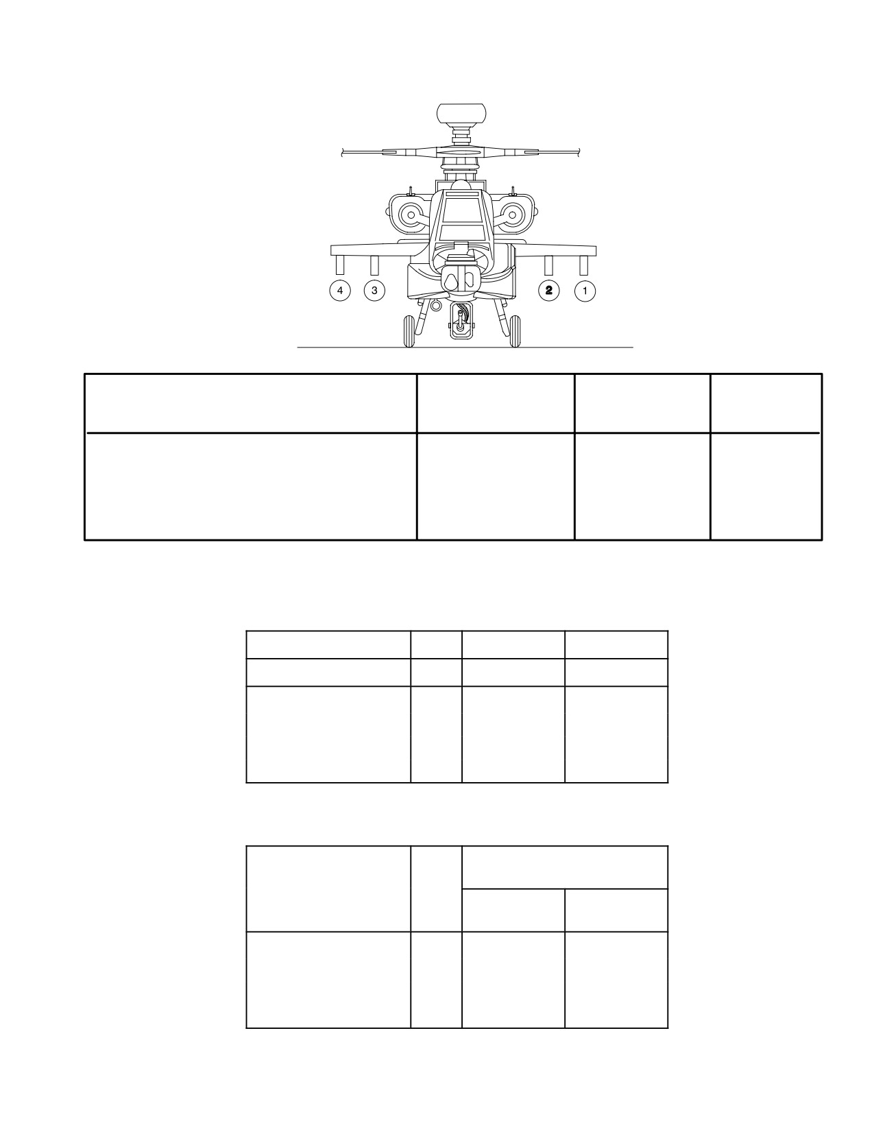
TM 1-1520-251-10
LBA5247
WEIGHT OF
MOMENT
ITEM
STATIONS
PAIR
(LBS)
(IN.LB/100)
M299 LONGBOW HELLFIRE LAUNCHERS
2 & 3 OR 1 & 4
286.0
542.46
M261 ROCKET LAUNCHERS
2 & 3 OR 1 & 4
173.6
340.12
AUXILIARY FUEL TANKS
2 & 3
280.0
539
AUXILIARY FUEL TANKS
1, 2, 3, 4
560.0
1078
Figure 6-2. External Stores and Stations
Table 6-5. Longbow HELLFIRE SAL C/K Missile Loading
Dummy Missile
1
99.0
188.82
Training Missile
1
99.0
188.82
Missile
1
99.0
188.82
Missile
2
198.0
377.64
Missile
3
297.0
566.46
Missile
4
396.0
755.28
Table 6-6. Longbow HELLFIRE RF Missile Loading
Inboard Station 2, 3 or
Outboard Station 1, 4
Accum
Moment
Item
Qty
Weight (lb)
(in.-lb/100)
Missile
1
106.0
201.5
Missile
2
212.0
403.0
Missile
3
318.0
604.5
Missile
4
424.0
806.0
Use or disclosure of this information is subject to the restriction(s) on the title page of this document.
6-13
TM 1-1520-251-10
Table 6-7.
2.75-Inch Rocket Loading
NOTE
When computing weight and balance, crewmember must remember to multiply each rocket type weight
(lb) and moment (in.-lb/100) by the quantity of that rocket type loaded onboard the aircraft. Failure to do so
will result in incorrect CG calculations. The SP calculates total rocket weight based upon rocket type (i.e:
6PD, 6RC) rather than warhead types (M151, M229 or M274). The weight calculation is based on LMP
settings, unless the load settings are altered in either crew station.
Inboard Station 2, 3 or
Outboard Station 1, 4
Rocket
Rocket Nomenclature
Weight (lb)
Moment
Type
per rocket
(in.-lb/100)
per rocket
Dummy
Dummy MK66 Rocket
23.0
44.80
6PD
MK66 Rocket Motor with Point Detonation, High
Explosive Warhead
23.0
44.80
6RC
MK66 Rocket Motor with Penetration, High Explosive
Warhead
24.0
46.44
6IL
MK66 Rocket Motor with Time, Illumination Warhead
24.3
46.18
6SK
MK66 Rocket Motor with Time, Smoke Warhead
22.5
43.42
6MP
MK66 Rocket Motor with Time, Multi-purpose
Submunition Warhead
27.4
51.96
6FL
MK66 Rocket Motor with Flechette Warhea
27.5
52.05
PD7
CRV7 Rocket Motor with Point Detonation, High
22.1
42.69
Explosive Warhead
RA7
CRV7 Rocket Motor with Armor Piercing, Point
25.8
49.26
Detonation, High Explosive Warhead
IL7
CRV7 Rocket Motor with Time, Illumination Warhead
23.5
44.08
SK7
CRV7 Rocket Motor with Time, Smoke Warhead
21.6
41.44
MP7
CRV7 Rocket Motor with Time, Multi - purpose
26.6
49.86
SubmunitionWarhead
FL7
CRV7 Rocket Motor with Flechette Warhead
20.0
38.68
Use or disclosure of this information is subject to the restriction(s) on the title page of this document.
6-14
TM 1-1520-251-10
Table 6-8. Ammunition Loading for M788 or M789 30mm Rounds (Aluminum Cartridges)
NOTE
When ADEN (brass cartridges) are used, multiply weight and moment by 1.354. When DEFA (steel car-
tridges) are used, multiply weight and moment by 1.343.
Weight
Moment
Weight
Moment
Number of Rounds
(lb)
(in.-lb/100)
Number of Rounds
(lb)
(in.-lb/100)
50
38.5
42
650
500.5
988
100
77.0
110
700
539.0
1063
150
115.5
189
750
577.5
1146
200
154.0
269
800
616.0
1221
250
192.5
346
850
654.5
1304
300
231.0
427
900
693.0
1379
350
269.5
504
950
731.5
1462
400
308.0
585
1000
770.0
1537
450
346.5
662
1050
808.5
1620
500
385.0
744
1100
847.0
1696
550
423.5
819
1150
885.5
1778
600
462.0
905
1200
924.0
1868
Table 6-9. Chaff Dispenser and Cartridges/Laser Warning Sensors ASE Equipment
Weight
Moment
Item
(lb)
(in.-lb/100)
IR Jammer
28.0
63.2
Radar Jammer
44.0
45.6
Radar Warning Receiver
14.3
44.6
Laser Warning Receiver with forward
19.2
58.3
and aft sensors
Forward Laser Warning Sensors (2 ea)
9.0
19
AFT Laser Warning Sensors (2 ea)
9.0
34
Chaff Dispenser M141 (Empty)
9.0
44.8
Table 6-10. Chaff Dispenser Cartridges
Weight
Moment
Number of Rounds
(lb)
(in.-lb/100)
30 Chaff Cartridges
10.0
49
Use or disclosure of this information is subject to the restriction(s) on the title page of this document.
6-15