HELICOPTER, ATTACK, AH-64D LONGBOW APACHE. TECHNICAL MANUAL (2002) - page 9
TM 1-1520-251-10
NOTE
NOTE
Video underlay is not available for display
If the map viewing range is greater than 25
on the TSD when the selected TYPE is any-
KM (13.5 NM), it will be changed to that
thing other than STICK.
viewing range when the SAT option is se-
lected.
d. TYPE Button. The TYPE multistate button is used
(3) SAT. The SAT option selects the CIB (Con-
to select the type of map underlay that will be displayed on
trolled Image Base) map as an underlay (satellite based
the TSD. Options are displayed only if there is map data
maps). If a CIB data file is currently loading for an area be-
available for that option loaded on a DTC. Selection of the
ing displayed on the MPD, the STICK map will be dis-
TYPE button will display the TYPE grouped options with the
played over a flat gray color. If that CIB data file is not
following selections:
available on the DTC, that area will change to the file not
found cue. If the map viewing range is larger than 25 KM
(1) DIG. The DIG option selects the digital map
(13.5 NM), the STICK map will be displayed.
as an underlay. If a DTED data file is loading or is not
available for the area being displayed on the MPD, the
(4) STICK. The STICK option selects the stick
STICK map will be displayed over a flat green or gray col-
map (standard TSD symbology) with no map underlay dis-
or as indicated by the GRAY button.
played.
e. LEVEL Button. The LEVEL two - state button is
used to select which DTED level (0, 1, or 2) of the DIG
map to be displayed as the underlay for the current view-
ing range. The DP will automatically select the best scale
for the selected viewing range (shown by a green arrow).
The LEVEL button will also override the automatic DP
selection and retain the new selection in RAM. This is se-
lectable only if the two levels of the DTED for the current
viewing range are available on the DTC. This button is re-
placed by the SCALE button when FFD data is selected to
be displayed.
e. SCALE Button. The SCALE multistate button is
used to select the level of DTED and the scale of the
Foundation Feature Data (FFD) to be displayed as the un-
derlay for the current viewing range. The DP will automati-
cally select the best scale of FFD for the selected viewing
range (shown by a green arrow). The SCALE button will
also override the automatic DP selection and retain the
new selection in RAM. These options are displayed only if
the associated map data is available on the DTC and the
scale can be supported in the current viewing range. If
FFD data is not available for a given scale, the option may
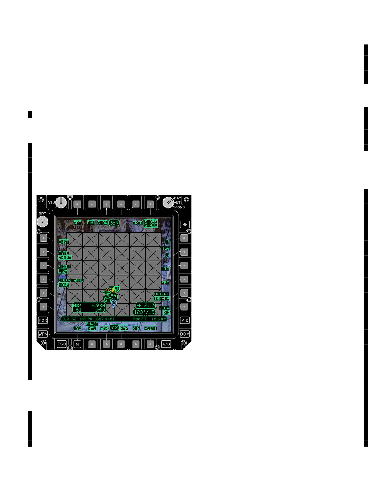
LBA5259
be replaced by a LVL 0, LVL 1, or LVL 2 option. Selecting
this option will automatically set the FFD button to NONE
Figure
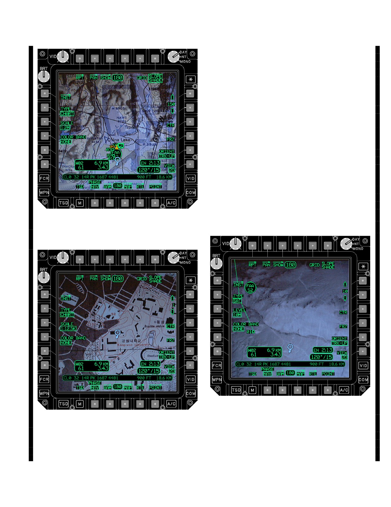
3A-102A.
File Not Found Cue
and change the LEVEL button to the selected DTED level.
(1)
1:5M and 1:2M Buttons. These SCALE op-
(2) CHART. The CHART option selects a CADRG
tions use DTED Level 0 data.
(Compressed ARC Digitized Raster Graphics) map as an un-
derlay. If a CARDG data file is currently loading for an area
(2)
1:1M and 1:500K Buttons. These SCALE
being displayed on the MPD, the STICK map will be dis-
options use DTED Level 1 data.
played over a flat gray color. If that CADRG data file is not
available on the DTC, that area will change to the file not
(3)
1:250K, 1:100K, 1:50K, and 1:2.5K But-
found cue (fig 3A-102A).
tons. These SCALE options use DTED Level 2 data.
Use or disclosure of this information is subject to the restriction(s) on the title page of this document.
Change 3
3A-119
TM 1-1520-251-10
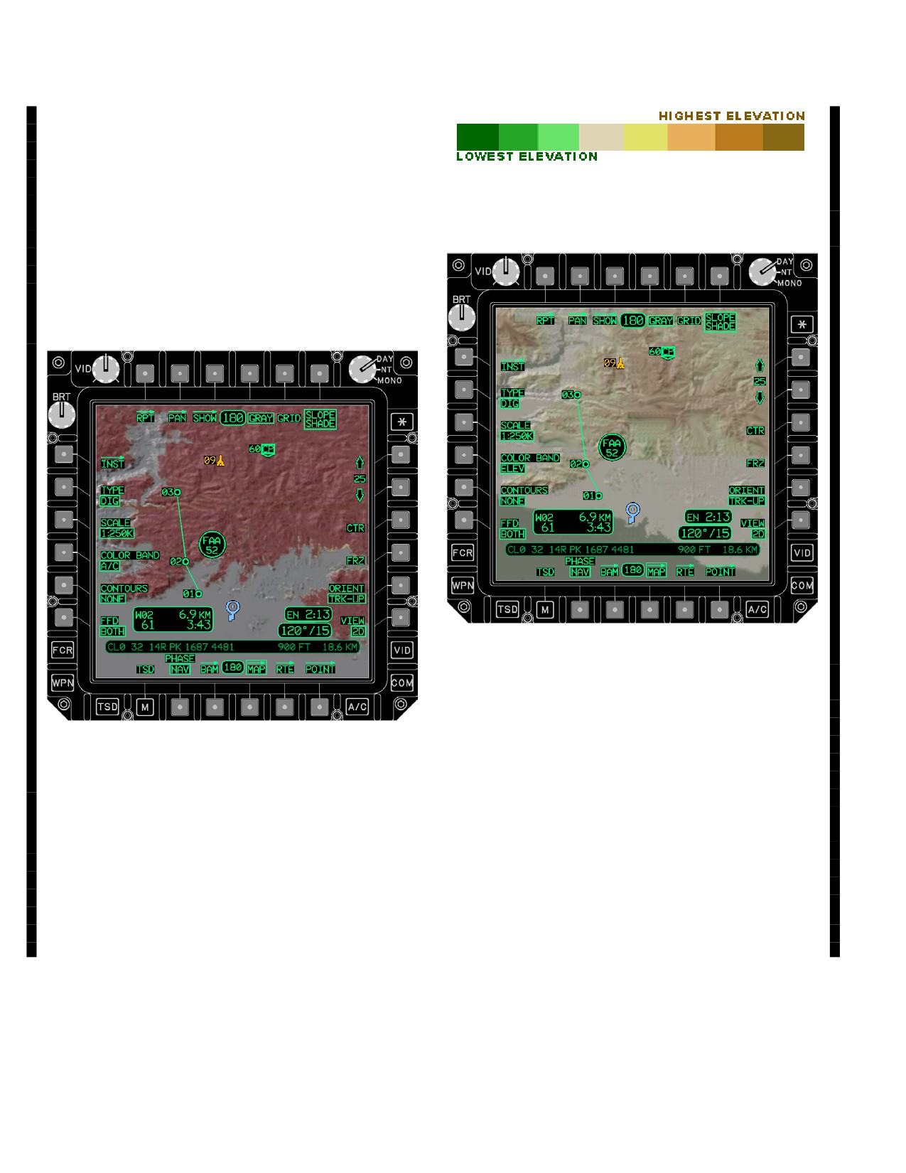
f. MAP COLOR BAND Button. The MAP COLOR
BAND multistate button provides the capability to select
two different elevation color schemes over a digital map
underlay and a disable option. The MAP COLOR BAND
button is only displayed if TYPE is set to DIG, CHART, or
LBA5261
SAT and DTED is available on the DTC. For DIG and
Chart maps, the color banding is based on the level of
Figure 3A-102C. ELEV COLOR BANDS
DTED corresponding to the SCALE button. For SAT
maps, it always is based on Level 2 DTED. (Color banding
will not be displayed in areas which do not have DTED in-
formation.)
LBA5262
Figure 3A-102D. ELEV COLOR BAND MAP
(2) ELEV Button. The ELEV button enables a
static color shading of the digital maps for elevation infor-
LBA5260
mation (fig 3A-102D). The elevation between bands will
be uploaded from the DTC and breaks up the correspond-
ing terrain into 8 color bands. If the MPD is displaying col-
ors, the various elevation bands are shaded from lower
Figure 3A-102B. A/C COLOR BAND MAP
terrain in dark green to higher terrain in dark brown. If the
MPD is displaying the colors in the mono mode, varying
shades of green (from light green to black) will be used.
(1) A/C Button. The A/C button enables a dy-
The overlays will all be a partially transparent version of
namic color shading of the digital maps for elevation infor-
that color to allow the map to be displayed under the
mation (fig 3A-102B). The terrain at or above the aircraft’s
elevation shading.
current altitude will be shaded in a transparent red and ter-
rain within 50 feet from the aircraft’s current altitude will be
(3) NONE Button. The NONE button disables
shaded in a transparent yellow.
color shading of the digital maps for elevation information.
Use or disclosure of this information is subject to the restriction(s) on the title page of this document.
3A-120
Change 3
TM 1-1520-251-10
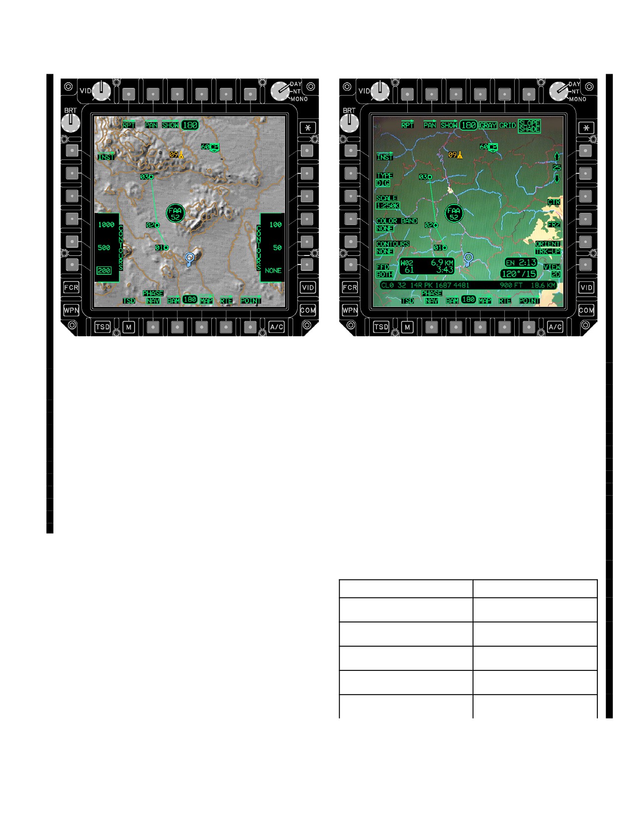
LBA5263
LBA5264
Figure 3A-102F. FFD MAP
Figure 3A-102E. CONTOUR LINES
h. FOUNDATION FEATURE DATA (FFD) But-
ton. Selecting the FFD button overlays the linear and
g. CONTOURS Button. Selecting the CONTOURS
area cultural foundation features on top of the DTED un-
multistate button displays the CONTOURS grouped options
derlay (fig 3A-102F). The options are AREAS, LINES,
with the currently selected contour boxed (fig 3A-102E). The
BOTH, and NONE (to disable the display of all foundation
CONTOURS button is only displayed if TYPE is set to DIG
features). The FFD button is only displayed if TYPE is set
and DTED is available on the DTC. This button is used to set
to DIG and FFD files are available on the DTC for the se-
the interval (in feet) between the contour lines. Contour lines
lected level of DTED. This button will be barriered if the
are displayed in brown. Contour line selections include: 1000,
FFD data available on the DTC cannot be displayed at the
500, 200, 100, 50, and NONE. The contour lines are based
selected map viewing range.
on the level of DTED corresponding to the SCALE button.
(Contour lines will not be displayed in areas which do not
NOTE
have DTED information.)
Colors for Foundation Feature Data are de-
fined and set by the user AMPS.
Table 3A-6B. Foundation Features
AREA FEATURES
LINEAR FEATURES
Moonscape (default no file)
Ground (default no file)
Ground
Ferry/Ford
Tree
Tree
Marsh
Road
Sand
Path
Use or disclosure of this information is subject to the restriction(s) on the title page of this document.
Change 3
3A-121
TM 1-1520-251-10
Table 3A-6B. Foundation Features - continued
AREA FEATURES
LINEAR FEATURES
Rock
Pipe
Snow/Ice
Cliff
Industrial
Gully
Boundary
Boundary
Airport
Runway
Railroad
Railroad
Tower
Tower
Water Structures
Industry/Building
Building
Bridge
Urban
Fence/Barrier
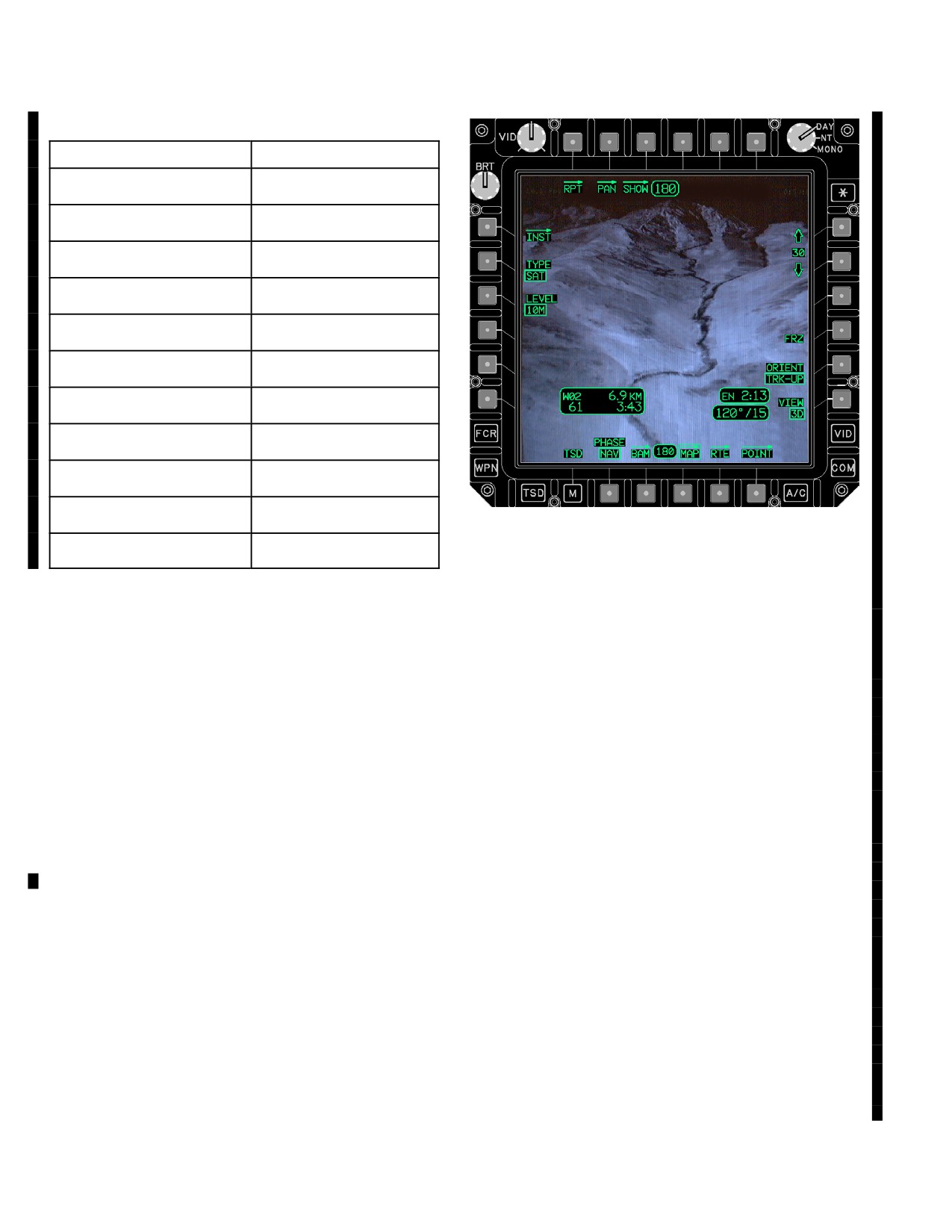
LBA5265
Water
Water
i. ORIENT Button. The ORIENT multistate button
Figure 3A-102G.
3D VIEW
is used to select the orientation of the map. The following
selections are available for orientation:
j. VIEW Button. The map VIEW two state button
(1) HDG - UP. When HDG - UP is selected, the
(R6) allows the user to select either a two dimensional
MAP uses the aircraft heading as the UP orientation.
(2D) map or a three dimensional (3D) map (fig 3A-102G).
This button will not be displayed if the MAP TYPE button
is set to STICK. This button is not selectable if DTED Lev-
(2) TRK - UP. The TRK - UP option is the default
el 1 Data is not available. When the map VIEW button is
selection. When the TRK - UP option is selected the air-
set to 3D, symbology will not be displayed on the map.
craft ground track is used as the UP orientation. The own-
ship icon will rotate as to the aircraft heading. If the ground
speed is not greater than 30 knots or the ground speed is
k. DTED Data Not Available Cue. Areas of the map
not within 30 degrees of magnetic heading, the orientation
which don’t have DTED information will be shaded in a
will be the same as heading up.
transparent purple. (If the underlay has a lot of color it may
look like it is slightly off color). This indication is displayed
when SLOPE SHADE, COLOR BAND, or CONTOURS
NOTE
are selected to be displayed.
Selection of N - UP could result in loss of sit-
uational awareness on the TSD.
3A.82.2 MAP PAGE - CHART Map. The MAP page
with CHART as the selected TYPE (fig 3A-102H) displays
a CADRG ( Compressed ARC Digitized Raster Graphics)
(3) N - UP. When N-UP (north-up) is selected, true
map as an underlay. This page provides access to the fol-
north is used as the UP orientation. The ownship icon on the
lowing unique functions:
TSD will rotate so it is always pointed in the aircraft heading
direction. In N-UP de-centered mode the ownship icon will
“ferris-wheel” around the display during aircraft pedal turns.
• L3
SCALE button
Use or disclosure of this information is subject to the restriction(s) on the title page of this document.
3A-122
Change 3
TM 1-1520-251-10
underlay for the current viewing range. The DP will auto-
matically select the best scale for the selected viewing
range (shown by a green arrow). The SCALE button will
also override the automatic DP selection and retain the
new selection in RAM. These options are displayed only if
the associated map data is available on the DTC and the
scale can be supported in the current viewing range.
(1)
1:5M and 1:2M Buttons. These SCALE op-
tions correspond with DTED Level 0 data.
(2)
1:1M and 1:500K Buttons. These SCALE
options correspond with DTED Level 1 data.
(3)
1:250K, 1:100K, 1:50K, and 1:2.5K But-
tons. These SCALE options correspond with DTED
Level 2 data.
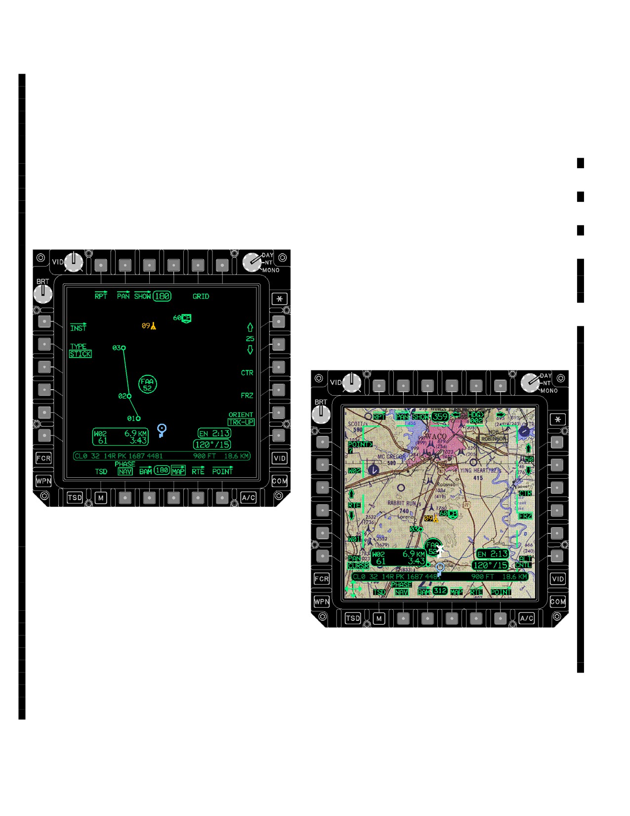
3A.82.3 MAP PAGE - SAT Map. The MAP page with
SAT as the selected TYPE (fig 3A-102J) displays a CIB
(Controlled Image Base) map as an underlay (satellite
based maps). This page provides access to the following
unique functions:
LBA5266
• L3
LEVEL button
Figure
3A-102H.
CHART MAP
LBA5268
LBA5267
Figure 3A-102J. SAT MAP
Figure 3A-102I. CHART (Ciy Graphics) MAP
a. LEVEL Button. The LEVEL two state button is
used to select which level (5m or 10m pixel resolution) of
a. SCALE. The SCALE multistate button is used to
the SAT map to be displayed as the underlay for the cur-
select the scale of the CHART map to be displayed as the
rent viewing range. The DP will automatically select the
Use or disclosure of this information is subject to the restriction(s) on the title page of this document.
Change 3
3A-122.1
TM 1-1520-251-10
best scale for the selected viewing range (shown by a
• T5
Pan HDG Data Entry button
green arrow). The LEVEL button will also override the au-
• T6
Right Pan HDG Arrow
tomatic DP selection and retain the new selection in RAM.
• L1
Pan POINT button
This button is not displayed if the map viewing range is
greater than 25KM (13.5 NM). This is selectable only if
• L2
Next WPT in RTE button
both types of map data are available on the DTC.
• L3
Forward in RTE Arrow button
• L3
Pan PITCH up Arrow
3A.82.4 MAP PAGE - STICK Map. The MAP page
with STICK as the selected TYPE (fig 3A-102K) removes
• L4
Back in RTE Arrow button
a digital map underlay and allows a video underlay to be
• L4
Pan PITCH entry button
seen underneath the stick map. This page does not have
• L5
Last WPT in RTE button
any unique buttons.
• L5
Pan PITCH down Arrow
• L6
PAN mode button
• R3
Pan ALT pitch up Arrow
• R4
Pan ALT entry button
• R5
Pan ALT pitch down Arrow
• R5
LAST PAN button
• R6
Pan ALT CNTL button
• R6
Pan 3D EYE button
LBA5269
Figure 3A-102K. STICK MAP
3A.83 PAN PAGE
The PAN page (fig 3A-103) provides the capability to pan the
TSD. The TSD may be panned along the current route, to a
coordinate data file location, UTM/LAT-LONG coordinate or
LBA5055B
to a cursor selected point. Selection of the PAN page will
cause the PAN controls to be displayed. CURSOR is the de-
Figure 3A-103. PAN Page
fault panning mode. Additionally, the cursor is active for selec-
tion of a pan destination in the NORM pan mode. When the
PAN page is selected the following unique functions are
3A.83.1 LAST PAN Button. When the map is made
available:
live, the DP will store the panned location and heading.
Selection of the LAST PAN button returns the map to that
• T4
Left Pan HDG Arrow
location and heading.
Use or disclosure of this information is subject to the restriction(s) on the title page of this document.
3A-122.2
TM 1-1520-251-10
3A.83.2 HDG Left/Right Arrow Buttons. Pressing the
a. ALT Up/Down Buttons. Selection of the ALT up/
left/right arrow buttons momentarily changes the pan
down ARROW buttons will change the altitude of the eye-
heading in 1 degree increments. Pressing and holding
point (above the ground). Selecting this button will change
changes the heading at 40 degrees per second.
the altitude by 10 feet. Selecting and holding this button
will change the altitude at a constant rate. This button is
3A.83.3 HDG Button. The HDG button is used for data
displayed when either the pan ALT CNTL or 3D EYE but-
entry of the pan heading.
ton is selected.
3A.83.4 POINT Button. Selection of the POINT button
b. ALT Entry Button. The pan ALT entry button is
allows entry of UTM/LAT - LONG coordinate or a coordi-
used to enter in the altitude of the eyepoint (above the
nate data file point number for pan destination.
ground). This button is displayed when either the pan ALT
CNTL or 3D EYE button is selected. When the map is ini-
tially frozen, this button is defaulted to the aircraft’s radar
3A.83.5 Next/Last WPT in RTE Buttons. Selecting
altitude.
the Next/Last WPT buttons momentarily pans forward
(up) to the next waypoint or back(down) to the previous
waypoint in a single step or continuous if pressed and
held.
3A.83.6 Forward/Backward in RTE Button. Selecting
the RTE button momentarily pans forward (up) to the next
waypoint or back(down) to the previous waypoint in small
increments or continuous if pressed and held.
3A.83.7 PAN Mode Button. The PAN two - state button
is used to select the mode of the PAN function. The follow-
ing selections are available for PAN mode:
a. CURSR Button. The CURSR button is the de-
fault selection for the PAN mode. The CURSR button al-
lows the crewmember to use the cursor thumb - force con-
trol to PAN the map. When in the cursor mode the map
underlay will move in the direction selected using the cur-
sor thumb-force controller. When in the CURSR PAN
mode the crewmember’s cursor changes to a directional
cursor. The cursor mode is changed to NORM and the
crewmember’s normal cursor is displayed for any of the
following reasons:
LBA5270
• PAN MODE changed to NORM
Figure
3A-103A.
3D EYE
• “Z - Axis” is selected with the cursor thumb - force
controller
3A.83.9
3D EYE Button. The pan 3D EYE button is
• PAN page button is deselected
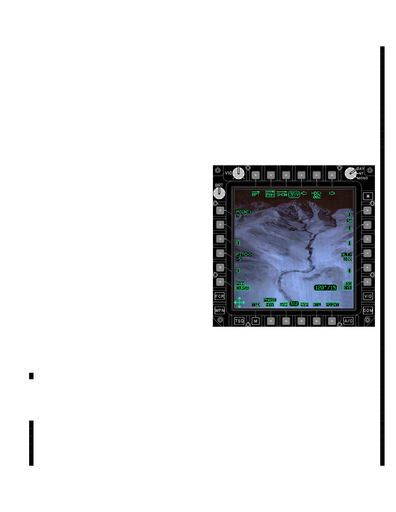
used to display the 3D map panning controls (fig
3A-103A). These controls are used to move the eye point
b. NORM Button. The NORM mode allows the cur-
or modify the viewing angle from the eyepoint. This button
sor to be used in a normal manner (selecting buttons, etc.)
is displayed when the map is 3D.
and to pan by jumping to a point.
a. PITCH Up/Down Button. Selection of the PITCH
3A.83.8 ALT CNTL Button. The pan ALT CNTL button
up/down ARROW buttons will change the viewing angle
is used to display the altitude panning controls. These
from the eyepoint (look up/down). Selecting this button
controls are used to change the altitude of the frozen map
will change the viewing angle 1 degree. Selecting and
for visibility shading and aircraft banding. This button is
holding this button will change the viewing angle at a
displayed when one of those two features is on and the
constant rate. This button is only displayed when the PAN
map is 2D.
3D EYE button is selected.
Use or disclosure of this information is subject to the restriction(s) on the title page of this document.
Change 3
3A-122.3
TM 1-1520-251-10
b. PITCH Entry Button. The pan PITCH data entry
button (L4) is used to enter in a viewing angle from the
eyepoint. This button is only displayed when the pan 3D
EYE button is selected. When the map is initially frozen,
this button is defaulted to the aircraft’s pitch.
c. ALT Up/Down Buttons. See para 3A.83.8.
d. ALT Entry Button. See para 3A.83.8.
3A.84 INST PAGE
NOTE
ADF MODE, FREQ, TEST, LAST, TONE,
IDENTIFY, EMER 500, EMER 2182 options
will not be displayed if the ADF system is not
LBA5054
enabled.
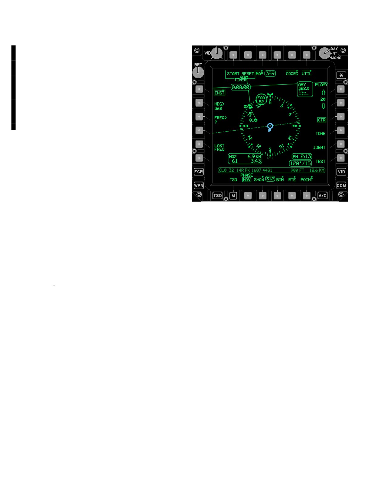
Figure 3A-104. INST Page
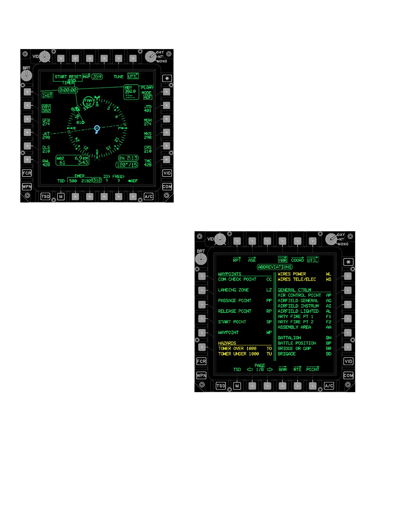
The INST page (fig 3A-104) is used to control the ADF
The INST page contains the following unique buttons:
System and provide the symbology necessary to perform
ADF navigation. A compass rose, heading select indicator
• T1
TIMER START/STOP button
(with inverse heading), and Non Directional Beacon iden-
• T2
TIMER RESET button
tifier/frequency status are displayed over the moving map
• T6
INST UTIL button
display. The next WAYPOINT status window is displayed
• L2
Selected Heading (HDG) button
in the lower left portion of the page. The ENDR and WIND
status windows are displayed in the lower right portion of
• L3
NDB FREQUENCY (FREQ) button
the page. The moving map is always dynamic unless the
• L5
LAST FREQUENCY (LAST FREQ)
INU data is invalid. NDB symbols whose free text match
• R4
TONE button
one of the presets can be selected from the INST and
• R5
IDENT button
INST UTIL. When selected the ADF will be tuned to the
matching preset.
• R6
TEST button
Use or disclosure of this information is subject to the restriction(s) on the title page of this document.
3A-122.4
Change 3
TM 1-1520-251-10
3A.84.1 TIMER START/STOP Button. The TIMER
3A.84.9 Timer Status Window. The timer status win-
START/STOP button is used to start/stop the digital timer
dow is used to display the elapsed time of the timer. The
readout.
window has a format of H:MM:SS and a range of 0:00:00
to 9:59:59.
3A.84.2 TIMER RESET Button. The TIMER RESET
3A.84.10 NDB Status Window. The NDB status win-
button is used to reset the digital timer readout displayed
dow displays in the upper right area of the INST page to
in the TIMER status window..
indicate the current frequency, station identifier letters,
and morse code to which the the ADF system is tuned.
The station identifier letters and morse code are displayed
3A.84.3 HDG Button. The HDG button is used to set
only when there is an identifier associated with the tuned
the numeric magnetic heading value for the Heading Se-
frequency or the tuned frequency is an emergency fre-
lect Indicator. The HDG button is only displayed if the INU
quency. If the frequency is invalid, it will be displayed
is operational.
WHITE.
3A.84.4 NDB FREQ (Frequency) Button. FREQ but-
3A.84.11 Compass Rose. The circular arrangement of
ton is used to manually set the numeric value of a NDB
tic marks (compass rose) rotates about a point to provide
frequency or commercial broadcasting station.
the instantaneous magnetic heading of the helicopter.
The compass rose is constructed with tic marks of three
sizes: long tics for 30° increments, medium tics for 10° in-
3A.84.5 LAST FREQ (Last Frequency) Button. LAST
crements, and short tics for 5° increments. Cardinal point
FREQ button is used to toggle between the current and pre-
heading values are displayed within the the compass rose
viously tuned NDB frequency or commercial broadcasting
and remain upright as the compass rose rotates on the
station.
page. The compass rose is placed at either the centered
or decentered position based on current selection of the
CTR button.
3A.84.6 TONE Button. Selecting the ADF TONE but-
ton causes the normal audio to be replaced by the 1000
3A.84.12 ADF Bearing Pointer. The ADF bearing
Hz tone for continuous wave (CW) operation.
pointer is displayed from the edge of the magnetic com-
pass rose, through the ownship, to the edge of the display
to indicate magnetic bearing of the current signal being re-
3A.84.7 IDENTIFY Button. Selecting the ADF IDEN-
ceived by the ADF system.
TIFY button causes the normal audio output to be filtered
for clarity.
3A.84.13 Heading Select Indicator. The heading
select indicator is displayed on the periphery of the mag-
3A.84.8 TEST Button. The TEST button is used to test
netic compass rose to indicate the magnetic heading
the ADF System circuits and strength of the station signal
value entered at the HDG select button. A heading bug
received. Selecting the TEST button causes the ADF
reciprocal is also displayed on the periphery of the com-
Bearing Pointer to momentarily shift approximately 90°
pass rose.
right from the present bearing for several seconds then
return to the original bearing. A faulty system circuit could
3A.85 INST UTILITY (UTIL) PAGE
possibly cause the ADF Bearing Pointer to shift to a value
other than approximately 90° right. The rate at which the
The UTIL page (fig 3A-105) is used to provide access to
ADF Bearing Pointer returns to the original bearing indi-
the stored preset ADF frequencies and utility selections.
cates the relative strength of the station signal received.
The presets can be edited or tuned based on crew inputs.
Use or disclosure of this information is subject to the restriction(s) on the title page of this document.
Change 2
3A-123
TM 1-1520-251-10
3A.85.4 ID Button. The NDB preset identifier ID button
is used to enter the NDB station identifier letters for the se-
lected ADF preset button.
3A.85.5 FREQ Button. The NDB preset frequency
FREQ button is used to enter the NDB station frequency
value for the selected ADF preset button.
3A.85.6 ADF Button. Selecting the ADF button alter-
nately toggles the ADF System between enabled and dis-
abled.
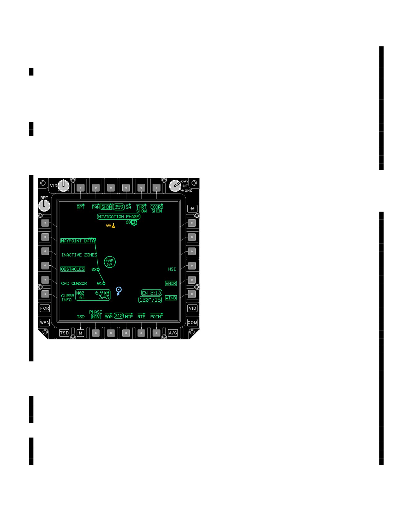
3A.86 ABBREVIATION (ABR) PAGE
The ABR page (fig 3A-106), a view only page, provides a
list of the correct two-letter identifications for a specific
waypoint, hazard, control measure, target, or threat. The
abbreviation page also includes the two-digit identifier for
each of the datums associated with its spheroid.
NOTE
LBA5053
There are no unique buttons on the ABR
page.
Figure 3A-105. INST UTIL Page
The INST UTIL page contains the following unique but-
tons:
• T5
TUNE button
• L2 - L6
ADF PRESET buttons
• R1
ADF MODE button
• R2 - R6 ADF PRESET buttons
• B4
ADF Preset Identifier (ID) button
• B5
ADF Preset Frequency (FREQ) button
• B6
ADF button
3A.85.1 TUNE Button. The NDB preset TUNE button
is used to tune the ADF receiver to the frequency of the
selected ADF preset station button.
3A.85.2 ADF Preset Buttons. The ADF preset buttons
are used to select specific ADF preset stations for tuning
or editing.
LBA5052
3A.85.3 MODE Button. Selecting the ADF MODE but-
ton displays ANT.
Figure
3A-106.
ABR Page
Use or disclosure of this information is subject to the restriction(s) on the title page of this document.
3A-124
Change 2
TM 1-1520-251-10
All available abbreviations are listed in tables 3A-7
Table 3A-8. Abbreviations Listing Page 2 Mode
through 3A-14 in their appropriate page mode.
ABBREVIATION NAME
ID
Table 3A-7. Abbreviations Listing Page 1 Mode
Checkpoint
CP
Abbreviation Name
ID
Company
CO
WAYPOINTS
Corps
CR
Comm Check Point
CC
Division
DI
Landing Zone
LZ
FARP Fuel Only
FF
Passage Point
PP
FARP Ammo Only
FM
Release Point
RP
FARP Fuel/Ammo
FC
Start Point
SP
Forwd Assemb Area
FA
Waypoint
WP
Grnd Lite/Sm Town
GL
Holding Area
HA
HAZARDS
IDM Subscriber
ID
Tower over 1000 (YELLOW)
TO
JVMF Subscriber
JV
Tower Under 1000 (YELLOW)
TU
NBC Area
NB
Wires Power (YELLOW)
WL
NDB Symbol
BE
Wires Tele/Elec (YELLOW)
WS
Railhead Point
RH
Regiment/Group
GP
GENERAL CTRLM
US Army
US
Air Control Point
AP
Airfield General
AG
FRIENDLY CTRLM
Airfield Instrum
AI
ADU Friendly (CYAN)
AD
Airfield Lighted
AL
Air Assault Frien (CYAN)
AS
Arty Fire Pt 1
F1
Air Cavalry Frien (CYAN)
AV
Arty Fire Pt 2
F2
Airborne Friend (CYAN)
AB
Assembly Area
AA
Armor Friend (CYAN)
AM
Battalion
BN
Armor Cav Friend (CYAN)
CA
Battle Position
BP
Bridge or Gap
BR
Brigade
BD
Use or disclosure of this information is subject to the restriction(s) on the title page of this document.
Change 2
3A-125
TM 1-1520-251-10
Table 3A-9. Abbreviations Listing Page 3 Mode
Table 3A-10. Abbreviations Listing Page 4 Mode
ABBREVIATION NAME
ID
ABBREVIATION NAME
ID
Av Maint Friend (CYAN)
MA
Armor Cav Enemy (RED)
EC
Chemical Friend (CYAN)
CF
Armor Enemy (RED)
AE
Av Maint Enemy (RED)
ME
Decon Friend (CYAN)
DF
Chemical Enemy (RED)
CE
Engineers Friend (CYAN)
EN
Decon Enemy (RED)
DE
ElecWar Friend (CYAN)
FW
Engineers Enemy (RED)
EE
Growth CTRLM FR1 (CYAN)
Z1
Elec War Enemy (RED)
WR
Growth CTRLM FR2 (CYAN)
Z2
Field Arty Enemy (RED)
EF
Growth CTRLM FR3 (CYAN)
Z3
Fixed Wing Enemy (RED)
WE
Fixed Wing Friend (CYAN)
WF
Growth CTRLM EN1 (RED)
Z4
Field Arty Friend (CYAN)
FL
Growth CTRLM EN2 (RED)
Z5
Heli Attack Frien (CYAN)
AH
Growth CTRLM EN3 (RED)
Z6
Heli Genrl Frien (CYAN)
FG
Heli Attack Enemy (RED)
EK
Hospital Friend (CYAN)
HO
Heli Genrl Enemy (RED)
HG
Infantry Friend (CYAN)
FI
Hospital Enemy (RED)
EH
Mech Infantry Fr (CYAN)
MI
Infantry Enemy (RED)
EI
Medical Friend (CYAN)
MD
Mech Infantry En (RED)
EM
TOC Friend (CYAN)
TF
Medical Enemy (RED)
EX
Unit ID Friend (CYAN)
FU
TOC Enemy (RED)
ET
Unit ID Enemy (RED)
EU
ENEMY CTRLM
Air Assault Enemy (RED)
ES
PREPLANNED TGT/THRT
Air Cavalry Enemy (RED)
EV
ADU AMX - 13 (RED)
AX
Air Defense Enemy (RED)
ED
ADU Aspide (RED)
AS
Airborne Enemy (RED)
EB
ADU Friendly (RED)
AD
Use or disclosure of this information is subject to the restriction(s) on the title page of this document.
3A-126
Change 3
TM 1-1520-251-10
Table 3A-11. Abbreviations Listing Page 5 Mode
Table 3A-12. Abbreviations Listing Page 6 Mode
ABBREVIATION NAME
ID
ABBREVIATION NAME
ID
ADU Gepard (RED)
GP
SAM SA-1 (RED)
1
SAM SA-2 (RED)
2
ADU Growth 1 (RED)
G1
SAM SA-3 (RED)
3
ADU Growth 2 (RED)
G2
SAM SA-4 (RED)
4
ADU Growth 3 (RED)
G3
SAM SA-5 (RED)
5
ADU Growth 4 (RED)
G4
SAM SA-6 (RED)
6
ADU Spada (RED)
SD
SAM SA-7 (RED)
7
ADU M1983 (RED)
83
SAM SA-8 (RED)
8
ADU Unknown (RED)
U
SAM SA-9 (RED)
9
AIR DEF 2S6/SA - 19 (RED)
S6
SAM SA-10 (RED)
10
Gun Air Defense (RED)
AA
SAM SA-11 (RED)
11
Gun Generic (RED)
GU
SAM SA-12 (RED)
12
Gun Marksman (RED)
MK
SAM SA-13 (RED)
13
Gun Sabre (RED)
SB
SAM SA-14 (RED)
14
Gun Self Prop (RED)
GS
SAM SA-15 (RED)
15
Gun Towed (RED)
GT
SAM SA-16 (RED)
16
Gun ZSU-23 (RED)
ZU
SAM SA-17 (RED)
17
Naval Systems (RED)
NV
SAM SAMP (RED)
SM
SAM SATCP (RED)
SC
Radar Battl Surv (RED)
SR
SAM Self Prop (RED)
SP
Radar TGT Acq (RED)
TR
SAM Shahine/R440 (RED)
SH
RBS-70 (RED)
70
SAM Starstreak (RED)
SS
SAM Blowpipe (RED)
BP
SAM Tigercat (RED)
TC
SAM Bloodhound (RED)
BH
SAM Stinger (RED)
ST
SAM Chapparal (RED)
CH
SAM Towed (RED)
SA
SAM Crotale (RED)
CT
SAM Vulcan (RED)
VU
SAM CSA-2/1/X (RED)
C2
Target Ref Point (RED)
TG
SAM Hawk (RED)
HK
SAM Javelin (RED)
JA
AIRY
AIR
SAM Patriot (RED)
PT
England Scott WALE
30
SAM Redeye (RED)
RE
SAM Rapier (RED)
RA
AUSTRALIAN NATL
AUS
SAM Roland (RED)
RO
Australian 66
3
Use or disclosure of this information is subject to the restriction(s) on the title page of this document.
Change 2
3A-127
TM 1-1520-251-10
Table 3A-13. Abbreviations Listing Page 7 Mode
Table 3A-14. Abbreviations Listing Page 8 Mode
ABBREVIATION NAME
ID
ABBREVIATION NAME
ID
BESSEL 1841
BES
INTERNATIONAL 1924
INT
Bukit Rimpah Indo
4
Camp Area Astro
5
Djarkarta Indo
6
European 1950
7
Gunung Segara
11
Geodetic Dat 1949
8
Tokyo Jap Kor Oki
40
Herat North
13
Tokyo Special
44
Hjorsey
14
Hu-Tzu-Shan
15
CLARK 1880
CL0
Qornoq
31
Adindan
1
Campo I Argentina
33
ARC 1950
2
Chua A Paraguay
34
Ghana
9
Corrego A Brazil
35
Liberia 1964
19
Prov 1956 S Amer
36
Merchich
22
Yacare Uraguay
37
Minna
24
Tananarive Observ
38
Sierra Leone 1960
32
Carthage
41
MODIFIED AIRY
MAI
Ireland 1965
17
CLARK 1866
CL6
Guam 1963
10
EVEREST 1948
MEV
Luzon
21
Kertau W Malaysia
18
NAD 27 ConUS
25
NAD 27 Alaska Can
26
WORLD GEO SYS 72
W72
Old Hawaii Maui
27
WGS72 Sino-Soviet
46
Old Hawaii Oahu
28
Old Hawaii Kauai
29
WORLD GEO SYS 84
W84
Luzon Special
43
Gunung Serindung
12
Local Astro
20
EVEREST SABAH
EVB
Montjong Low Indo
23
TIMBALI E MALAYS
39
WGS 84 Special
45
WGS 84 Default
47
EVEREST 1830
EVE
Indian Thai Viet
16
Indian Special
42
Use or disclosure of this information is subject to the restriction(s) on the title page of this document.
3A-128
Change 2
TM 1-1520-251-10
3A.87 SHOW PAGE
• L6
CURSOR INFO button
• R4
HSI button
The SHOW page manages the symbology displayed on
the TSD during the PHASE selected. Like buttons that are
• R5
ENDR button
selected/deselected in one PHASE are not automatically
• R6
WIND button
selected/deselected in the other PHASE. The buttons that
are boxed in (fig 3A-107) are defaulted upon power being
a. SA Page Button. Selecting the SA button dis-
applied to the display processor. The moving map is dis-
plays the SA page on the TSD.
played on the SHOW page. Symbols will be displayed or
removed as buttons are selected if they are in the dis-
b. THRT SHOW Page Button. Selecting the THRT
played map area. The SHOW page has three subpages:
SHOW button displays the THRT SHOW page on the
SA, THRT SHOW, and COORD SHOW.
TSD.
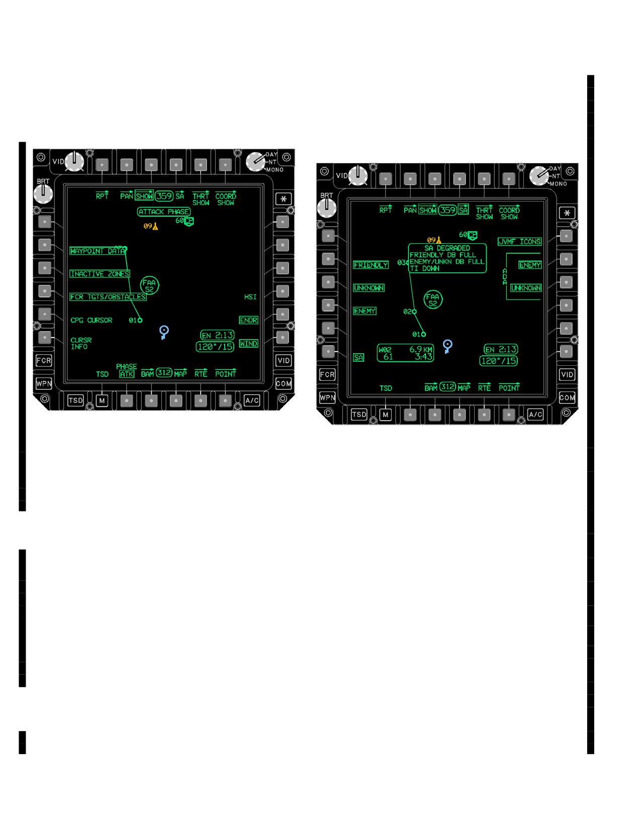
3A.87.1 SHOW Page - Navigation (NAV). The NAV
c. COORD SHOW Page Button. Selecting the
PHASE of the SHOW page (fig 3A-107) is used to provide
COORD SHOW button displays the COORD SHOW page
access to navigation data.
on the TSD.
d. WAYPOINT DATA Button. Selecting the WAY-
POINT DATA button displays the next waypoint status
window on the TSD.
e. INACTIVE ZONES Button. Selecting the INAC-
TIVE ZONES button displays the inactive fire zones on
the TSD.
f. OBSTACLES Button. Selecting the OBSTA-
CLES button displays obstacles on the TSD.
g. PILOT or CPG CURSOR Button. Selecting the
PILOT or CPG CURSOR button (crewstation dependant)
displays the other crewmember’s cursor when the oppo-
site crewmember has the cursor on the TSD.
h. CURSOR INFO Button. Selecting the CURSOR
INFO button displays the cursor position in UTM coordi-
nates, distance from the ownship (KM or NM), and DTED
elevation (if available) within the CURSOR POSITION
LBA5051B
status window. The CURSOR POSITION status window is
only displayed when the CURSOR INFO button is se-
Figure
3A-107.
SHOW Page (NAV PHASE)
lected.
i. HSI Button. Selecting the HSI button displays
The NAV PHASE of the SHOW page contains the follow-
the magnetic compass rose on the TSD.
ing unique buttons:
• T4
SA page
j. ENDR Button. Selecting the ENDR button dis-
plays the ENDR status window on the TSD.
• T5
THRT SHOW page
• T6
COORD SHOW page
k. WIND Button. Selecting the WIND button dis-
• L2
WAYPOINT DATA button
plays the WIND status window on the TSD.
• L3
INACTIVE ZONES button
l. NAVIGATION Status Window. The NAVIGA-
• L4
OBSTACLES button
TION status window displays the status of the PHASE
• L5
PLT (or CPG) CURSOR button
button.
Use or disclosure of this information is subject to the restriction(s) on the title page of this document.
Change 3
3A-129
TM 1-1520-251-10
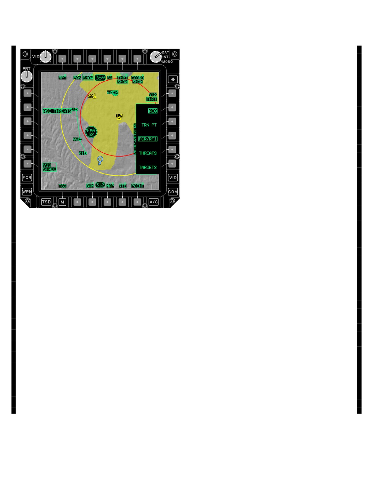
3A.87.2 SHOW Page - Attack (ATK). The ATK
3A.87.3 SHOW Page
- Situational Awareness (SA)
PHASE of the SHOW page (fig 3A-108) is used to provide
Page. The SA page (fig 3A-109) is used to control the
access to battlefield data.
display of situational awareness data and other JVMF re-
lated icons. The options on this page are not independent
between phases. Selection of the SA page will clear SA
degraded advisory.
LBA5050B
LBA5049C
Figure 3A-109. SHOW SA Page
Figure 3A-108. SHOW Page (ATK PHASE)
The SA page contains the following unique buttons:
The ATK PHASE of the SHOW page contains the follow-
• L2
FRIENDLY button
ing unique buttons:
•
L3
UNKNOWN button
• T2
CURRENT ROUTE button
• L4
ENEMY button
• L4
FCR TGTS/OBSTACLES button
•
L6
SA button
a. CURRENT ROUTE Button. Selecting the CUR-
• R1
JVMF ICONS button
RENT ROUTE button displays the current route and all of
its selected points, including direct-to navigation points on
• R2
ADA ENEMY button
the TSD.
• R3
ADA UNKNOWN button
a. FRIENDLY Button. Selecting the FRIENDLY
button displays the blue FRIENDLY SA icons on the TSD.
b. FCR TGTS/OBSTACLES Button. Selecting the
FCR TGTS/OBSTACLES button displays the low priority
b. UNKNOWN Button. Selecting the UNKNOWN
FCR targets or obstacles on the TSD.
button displays the yellow UNKNOWN SA icons on the
TSD.
c. ATTACK Status Window. The ATTACK status
c. ENEMY Button. Selecting the ENEMY button
window displays the status of the PHASE button.
displays the red ENEMY SA icons on the TSD.
Use or disclosure of this information is subject to the restriction(s) on the title page of this document.
3A-130
Change 3
TM 1-1520-251-10
d. Situational Awareness (SA) Button. This but-
3A.87.4 SHOW Page - THRT SHOW (THRT VIS). The
ton is displayed when the PSN button is not displayed. Se-
THRT SHOW page is used to control the display of
lecting the SA button toggles the display of all SA icons
threats, rings, and intervisibility shading. The THRT
ON and OFF.
SHOW page toggles between THRT and OWN via the
VIS button to allow for display of either type of rings and
e. JVMF ICONS Button. Selecting the JVMF
intervisibility. The options on this page are not indepen-
ICONS button displays the Message to Observer, Adjust
dent between phases.
Fire, Spot Report, Airfire Mission, Airfire Observer, Situa-
tion Report, Call for Fire, and Check Fire Symbols.
NOTE
f. ADA ENEMY Button. Selecting the ADA EN-
EMY button displays the red ENEMY ADA SA icons on
the TSD.
If the threat has a detection range of 4.8 KM
or less, the map will display real intervisibil-
g. ADA UNKNOWN Button. Selecting the ADA
ity shading only if Level 2 DTED data is
UNKNOWN button displays the yellow UNKNOWN ADA
available for that threat. If the detection
SA icons on the TSD.
range is between 4.8 and 19.2 KM, the map
will only use Level 1. If it is greater than 19.2
h. SA Degraded Status. The SA Degraded Status
KM, the map will only use Level 0. Therefore
window is provided when the SA Friendly database be-
if VIS SHADE is selected for a threat and
comes full, the SA Enemy/Unknown database becomes
the Level of DTED required isn’t available
full, or if the Tactical Internet is down after receiving up-
for that area, the map will shade the entire
dates to the SA database.
ring, showing the worst case.
Use or disclosure of this information is subject to the restriction(s) on the title page of this document.
Change 3
3A-131
TM 1-1520-251-10
a. ASE THREATS Button. Selecting the ASE
THREATS button displays the RFI/RLWR detected
threats on the TSD.
b. TRN PT ALT UP/DOWN Arrow Buttons. Select-
ing the TRN PT ALT up/down arrow buttons allows the
crewmember to change the altitude for the intervisibility
shading of the TRN PT. A single push of the button
changes the terrain point altitude in 5 foot increments.
Holding the button continuously changes the altitude.
c. TRN PT ALT Data Entry Button. Selecting the
TRN PT ALT button allows the crewmember to enter an
altitude via the KU which modifies the intervisibility of the
TRN PT based on a given altitude.
d. VIS SHADE Button. Selecting the VIS SHADE
button displays intervisibility shading for all items corre-
sponding to the buttons selected in the bracket.
e. VIS Button. Selecting the VIS button toggles be-
tween THRT and OWN. THRT shows where the selected
LBA5272A
icons can see the aircraft at its current altitude. The OWN op-
tion shows where the aircraft could see at the given altitude.
Figure
3A-109A.
THRT SHOW Page - VIS THRT
NOTE
Selected
Intervisibility and rings will only be displayed
if the associated icon is currently enabled
for display. Threat intervisibility will only be
The THRT SHOW page with the VIS THRT option se-
displayed for threats which have detected
lected (fig 3A-109A) contains the following unique but-
ranges (uploaded from the DTC).
tons:
f. AQC Option. Selecting the AQC option displays
• L2
ASE THREATS button
threat rings for the selected AQC TXX source (when appli-
• L3
TRN PT ALT up arrow button
cable).
• L4
TRN PT ALT data entry button
g. TRN PT Option. Selecting the TRN PT option dis-
• L5
TRN PT ALT down arrow button
plays threat rings for both the PLT and CPG terrain points.
• L6
VIS SHADE button
h. FCR/RFI Option. Selecting the FCR/RFI option
• R1
VIS button
displays threat rings for FCR targets which have been
• R2
AQC button
merged with RFI threats.
• R3
TRN PT button
i. THREATS Option. Selecting the THREATS op-
• R4
FCR/RFI button
tion displays threat rings for preplanned threats.
• R5
THREATS button
j. TARGETS Option. Selecting the TARGETS op-
• R6
TARGETS button
tion displays threat rings for preplanned targets.
Use or disclosure of this information is subject to the restriction(s) on the title page of this document.
3A-132
Change 3
TM 1-1520-251-10
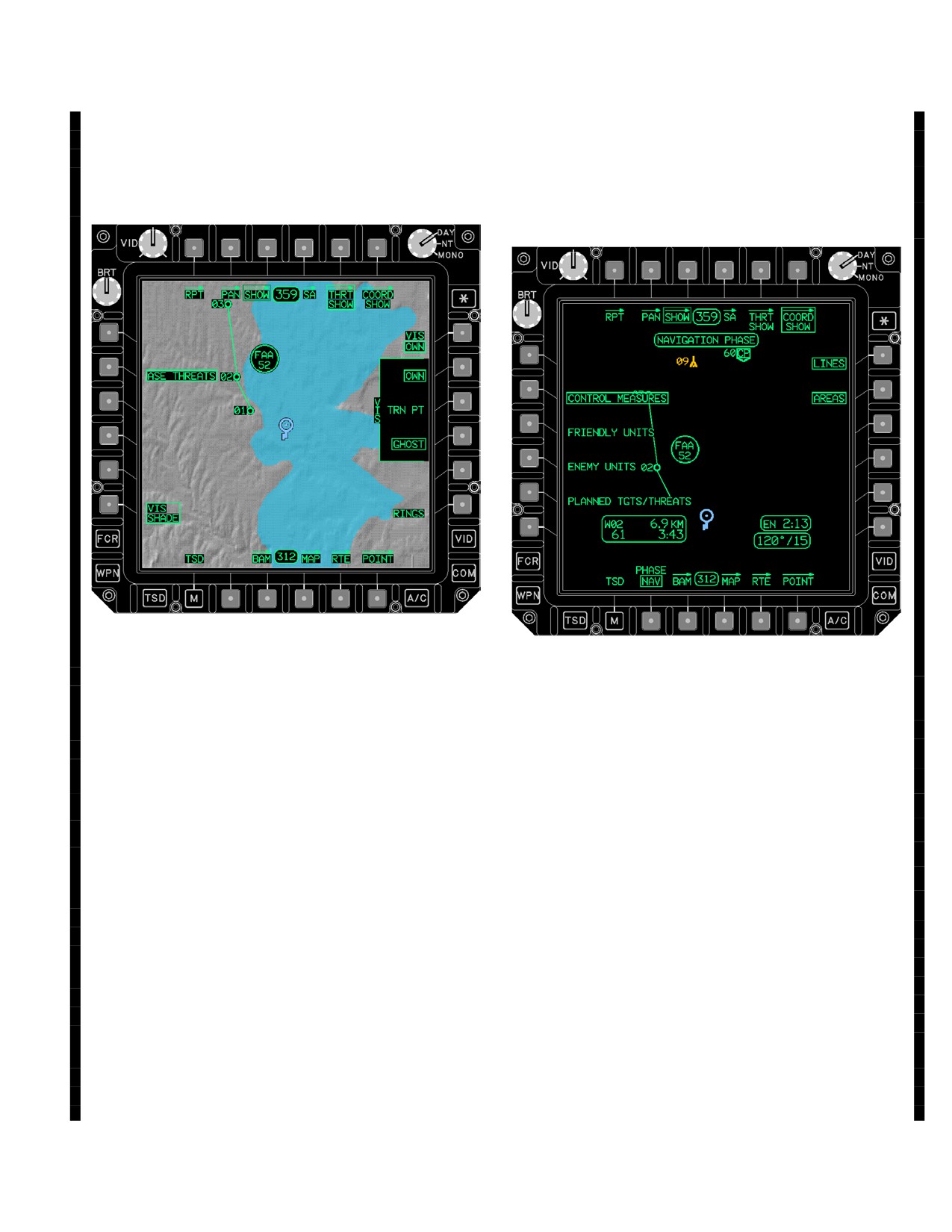
3A.87.5 SHOW Page - THRT SHOW (VIS OWN).
d. RINGS Button. Selecting the RINGS button dis-
Selecting the THRT SHOW page (fig 3A-109B) is used to
plays rings for all selected RINGS maintained options.
control the display of ownship relative rings and intervisi-
bility shading.
3A.87.6 SHOW Page
- COORD SHOW
(NAV
PHASE). The COORD SHOW page (fig 3A-109C) is
used to provide access to additional battlefield data.
LBA5273A
LBA5274A
Figure 3A-109B. THRT SHOW Page - VIS OWN
Figure 3A-109C. COORD SHOW Page (NAV)
Selected
The COORD SHOW page (NAV Phase) (fig 3A-109C)
The THRT SHOW page with the VIS OWN option selected
contains the following unique buttons:
contains the following unique buttons:
• L2
CONTROL MEASURES button
• R2
OWN button
• L3
FRIENDLY UNITS button
• R3
TRN PT button
• L4
ENEMY UNITS button
• L5
PLANNED TGTS/THREATS button
• R4
GHOST button
• R1
LINES button
• R6
RINGS button
• R2
AREAS button
a. OWN Option. Selecting the OWN option enables
a. CONTROL MEASURES Button. Selecting the
the display of a lethality ring and/or intervisibility for the
CONTROL MEASURES button displays all of the control
ownship.
measures except the enemy units and friendly units on the
TSD. Deselecting the CONTROL MEASURES button re-
b. TRN PT Option. Selecting the TRN PT option
moves all of the control measures except the enemy units
enables the display of lethality rings and/or intervisibility
and friendly units and those control measures that are
for both the PLT and CPG terrain points.
part of the current route, including direct - to navigation.
c. GHOST Option. Selecting the GHOST option
b. FRIENDLY UNITS Button. Selecting the
enables the display of a lethality ring and/or intervisibility
FRIENDLY UNITS button displays the friendly unit control
for the ghostship.
measures on the TSD.
Use or disclosure of this information is subject to the restriction(s) on the title page of this document.
Change 3
3A-132.1
TM 1-1520-251-10
c. ENEMY UNITS Button. Selecting the ENEMY
3A.88 DELETED
UNITS button displays the enemy unit control measures
on the TSD.
3A.89 POINT PAGE
d. PLANNED TGTS/THREATS Button. Selecting
The POINT page (fig 3A-110) provides the ability to manage
the PLANNED TGTS/THREATS button displays the
the waypoints/hazards, control measures, and target/threats
planned and stored targets and threats on the TSD.
files. The POINT page defaults to reviewing the active des-
tination point. The crewmember can select any waypoint,
e. LINES Button. Selecting the LINES button dis-
hazard, control measure, and target/threats for review.
plays LINES on the TSD.
f. AREAS Button. Selecting the AREAS button
displays AREAS on the TSD.
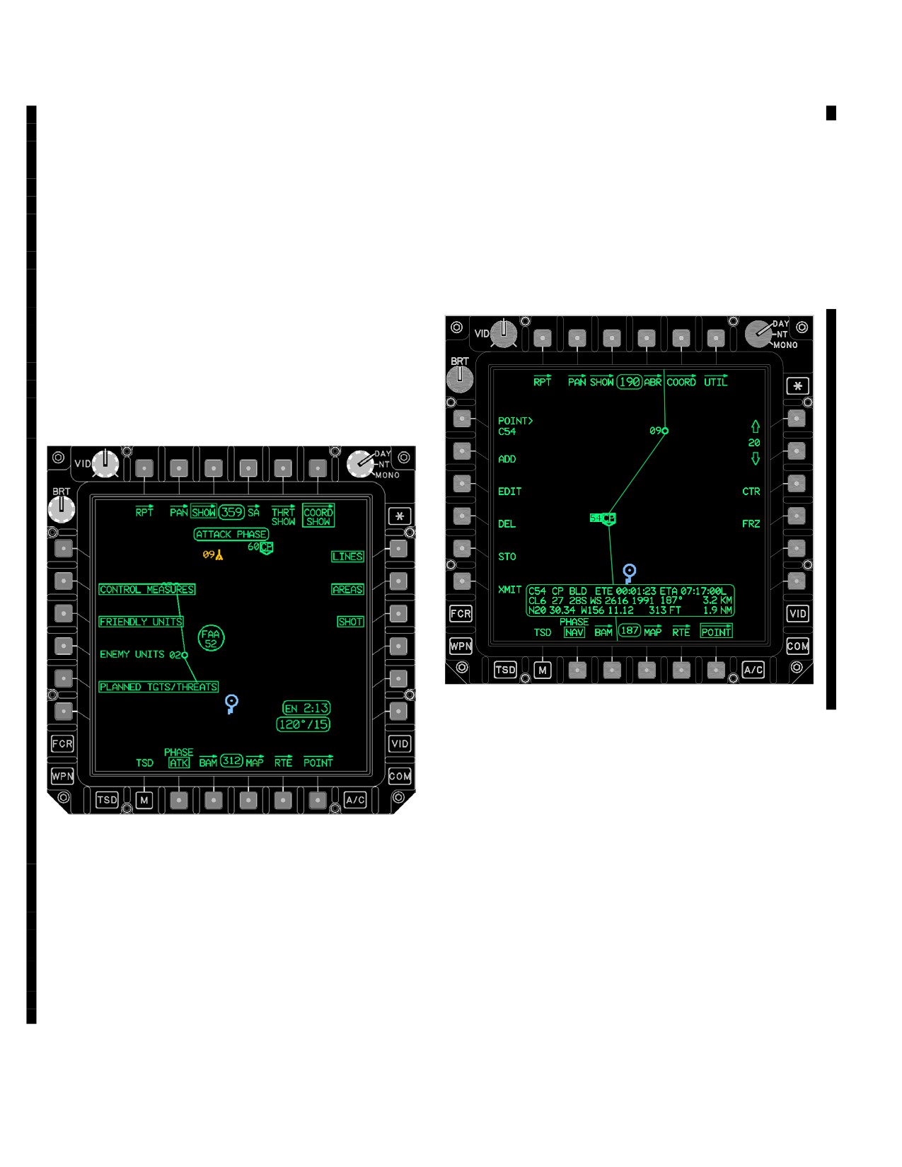
3A.87.7 SHOW Page - COORD SHOW (ATK PHASE).
The COORD SHOW page (fig 3A-109D) is used to pro-
vide access to additional battlefield data.
LBA5048A
Figure 3A-110. POINT Page
The POINT page contains the following unique buttons:
LBA5275A
• L1
POINT button
• L2
ADD button
Figure 3A-109D. COORD SHOW Page (ATK)
• L3
EDIT button
The COORD SHOW page (ATK Phase) contains the fol-
• L4
DEL button
lowing unique button:
• L5
STO button
• R3
SHOT button
• L6
XMIT button
SHOT Button. Selecting the SHOT button displays the
3A.89.1 POINT Button. Selecting the review POINT
shot - at Xs on the TSD.
button arms the KU for entry of the point type (W, H, C, or
T) and the point number. The cursor can also be used to
select the point.
Use or disclosure of this information is subject to the restriction(s) on the title page of this document.
3A-132.2
Change 3
TM 1-1520-251-10
3A.89.2 ADD Button. The ADD button allows the cre-
the default, enter a coordinate using the KU, enter a point
ation of a new waypoint, hazard, control measure, or threat
number using the KU, or select a point on the map using the
which is added to the coordinate data files. Selecting the
cursor. An example of each is:
ADD button calls up the IDENT button and the Point TYPE
• UTM: 11SGQ52184911
buttons. The system defaults to the waypoint (WP) button in
• LAT/LONG: N742594W1205768
the NAV phase and to the target (TGT) button in the ATK
phase. At this point, the cursor can be used to add the default
• Point Type and Point Number : C95.
point as indicated by the Point TYPE button. The free text will
• Pick a point off the map using the cursor (the
be defaulted to the point type and point number. The cursor
cursor coordinate will update in the review
position when the cursor acknowledge was selected will be
status window).
used for the location. The point altitude will be based off of the
DTED information if available for the specified location.
Entry convention for LAT/LONG is one contiguous string with
Otherwise, the altitude is defaulted to the elevation of the
no decimal points in degrees, minutes, and hundredths of
ground below the aircraft.
minutes. Latitude Northing degrees will contain two digits;
Longitude Easting degrees will contain three digits with lead-
a. Point TYPE Buttons. The point TYPE buttons
ing zeros. Once the KU ENTER is selected, the button label
are displayed when the ADD button is selected. These
will change to ALTITUDE. The crew can accept the default or
buttons are used to select the type of point to be added to
enter an altitude using the KU. Once the KU ENTER is se-
the file. Selecting a point TYPE button sets the type of
lected, the system displays the added/modified point in the
coordinate data according to the respective selection.
review status window and the ADD or EDIT button is dese-
When the waypoint, hazard, control measure, or threat file
lected.
is full, the respective point TYPE buttons are not select-
able.
When editing a point, the defaults are set to the current
values for that point. When adding a point, the defaults are
(1) Waypoint (WP) Button. Selecting the WP
set as follows. For the identifier, the default is set per the
button changes the type of point to be added to waypoint.
TYPE button. The free text is defaulted to the point type
The identifier defaults to WP.
and number. The coordinate is defaulted to the present
position of the aircraft. If DTED information for the speci-
(2) Hazard (HZ) Button. Selecting the HZ but-
fied location is available, the altitude is defaulted to alti-
ton changes the type of point to be added to hazard. The
tude in the DTED information for the entered coordinate.
identifier defaults to a Tower Under 1000 feet TU.
Otherwise the altitude is defaulted to the Mean Sea Level
(3) Control Measure (CM) Button. Selecting the
(MSL) of the ground below the aircraft.
CM button changes the type of point to be added to control
3A.89.3 EDIT Button. Selecting the EDIT button calls
measure. The identifier defaults to a Check Point CP.
up the edit FREE button with the last valid coordinate data
(4) TARGET (TG) Button. Selecting the TG but-
selected and the free text of the selected point.
ton changes the type of point to be added to target/threat.
3A.89.4 Delete (DEL) Button. Selecting the DEL button
The identifier defaults to a Target TG.
calls up the delete POINT button with the last valid coordinate
data selected and the DELETE YES/NO buttons.
b. Identifier (IDENT) Button or EDIT Button. The ID-
ENT button is displayed when either ADD or EDIT is se-
a. Delete YES Button. Selecting the Delete YES
lected. The crew can either accept the default by pressing the
button will delete the currently selected waypoint, hazard,
KU ENTER or type in a two character point identifier for the
control measure, or target/threat that has been selected
selected type of point and select the KU ENTER. Once the
by the delete POINT button.
KU enter is selected, the button label will change to FREE.
The crew can either accept the default or enter in up to three
b. Delete NO Button. Selecting the Delete NO but-
letter description. Once the KU ENTER is selected, the button
ton will cause the system to abort the delete process and
label will change to UTM LAT/LONG. The crew can accept
deselect the DEL button.
Use or disclosure of this information is subject to the restriction(s) on the title page of this document.
Change 3
3A-132.3
TM 1-1520-251-10
3A.89.5 Store (STO) Button. Selecting the STO button
a. TYPE Button. The TYPE two state button is
calls up the NOW button used to store a waypoint or target
used to determine what type of point is going to be stored
within the coordinate data files using the flyover store pro-
when the NOW button is selected or the STORE button on
cess. The review status window displays only the waypoint
the LHG is selected. The TYPE toggles between WP and
identifier, type, and altitude associated with the point file data
TG. The TYPE button defaults based on the phase se-
to be added. The default values used are as follows:
lected when STO is selected:
• Point Type: W or T
• Point Number: The next lowest number availa-
• WP is the default in the NAV phase
ble for the appropriate coordinate file
• TG is the default in the ATK phase
• Point Identifier: WP or TG
• Free Text: FLY
b. NOW Button. The NOW button commands the
• Altitude: Present position MSL terrain altitude if
system to add a point using the current aircraft position
the valid necessary information of ADS and Radar
and altitude. The free text will read FLY for points stored
Altimeter is available.
using the flyover method.
Use or disclosure of this information is subject to the restriction(s) on the title page of this document.
3A-132.4
Change 3
TM 1-1520-251-10
NOTE
The system will add a target unless the
POINT page is displayed with STO selected
and TYPE is set to WP.
c. TADS LOS Store Procedure. An optional method
to store a waypoint or target using the STO button is to desig-
nate the point to be stored using the TADS laser. The CPG
must sight select TADS and arm the aircraft. After selecting
the STO button the CPG will point the TADS laser to the cor-
rect location and lase for range and select the STORE push-
button on the LHG. This will cause the system to add a way-
point or target to the system using the offset from the TADS
laser range to the aircraft position and the aircraft altitude.
TADS LOS can also store points using Auto Range/Default
Range or Manual Range. Points can also be stored using
HMD and Auto Range/Default Range or Manual Range. The
free text will reflect the LOS used to store the target, TAD or
HMD.
3A.89.6 XMIT Button. Selecting the XMIT button calls up
LBA5047
the send POINT button with the last valid coordinate data se-
lected, IDM subscriber buttons, and the transmit SEND but-
ton used to send a waypoint, hazard, control measure, or tar-
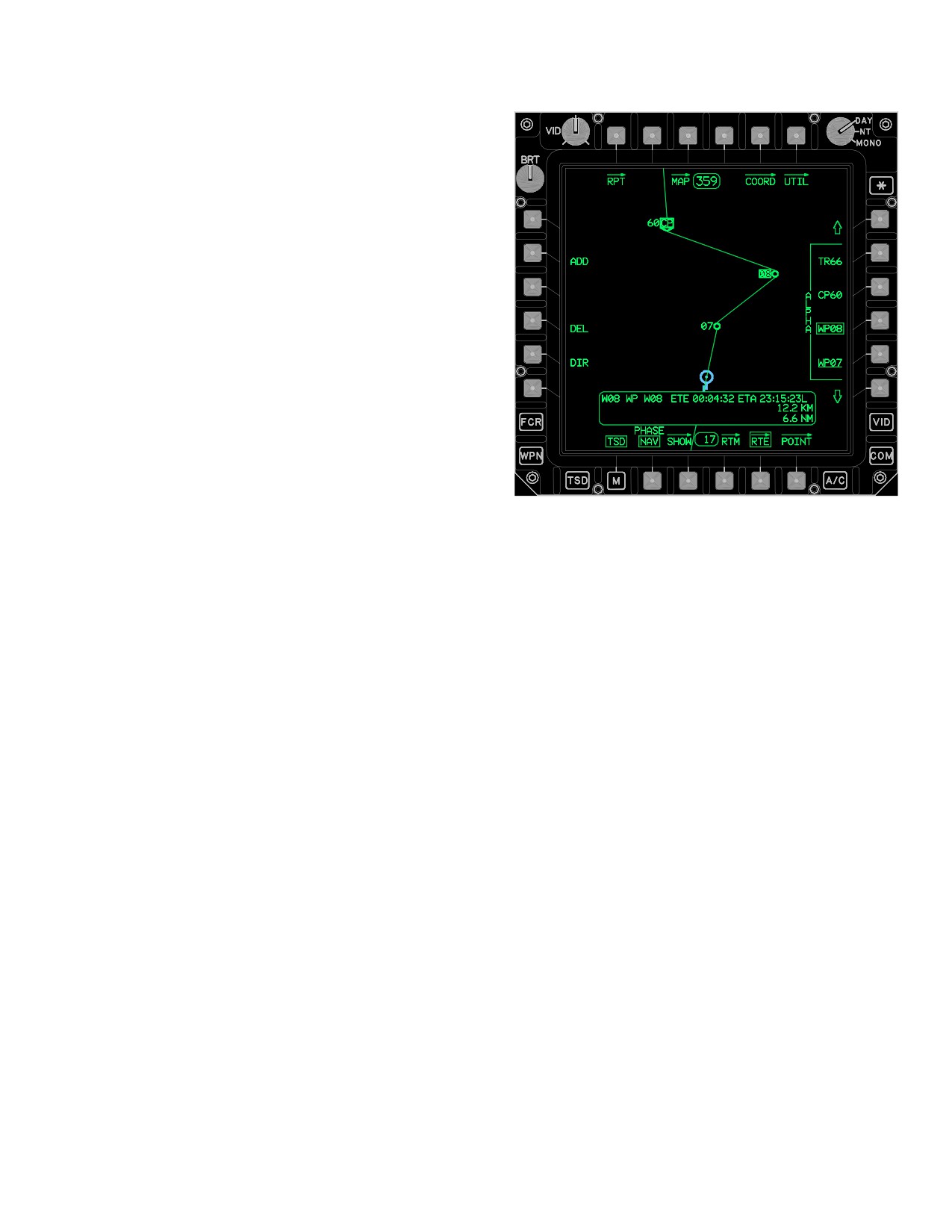
Figure 3A-111. RTE Page
get/threat over the IDM communication network.
3A.89.7 POINT Review Status Window. The POINT re-
The RTE page also contains the following unique buttons:
view status window in the lower part of the mapping area pro-
vides coordinate data pertaining to a selected point depend-
• L1
POINT button
ing upon the moding of the POINT page. The data fields
• L2
ADD button
displayed within the status window include the following:
• L4
DEL button
• Point Type and Number
• L5
DIR button
• Point Identifier
• R1
Route Scroll Up button
• Free Text Identifier
• R2 - R5 Route POINT buttons
• Estimated Time Enroute (ETE)
• R6
Route Scroll Down button
• Estimated Time of Arrival (ETA)
• Spheroid
• B4
RTM button
• Datum
3A.90.1 POINT Button. The POINT button is displayed
• UTM Coordinates
when either the ADD button or DIR button is selected. The
crew must enter the existing point type using the KU.
• Bearing
• Distance to Go (Km)
3A.90.2 ADD Button. Selecting the ADD button allows the
• Latitude/Longitude Coordinates
crew to add existing waypoints, hazards, and control mea-
• Altitude
sures to the current route. The system does not permit add-
ing a target or threat to the route. To add a point to the route,
• Distance to Go (NM)
first select the ADD button, and the system calls up the
3A.90 ROUTE (RTE) PAGE
POINT button. Next, select the POINT button and enter the
point to be added using the KU, or use the cursor to select
The RTE page (fig. 3A-111) allows the crewmember to ac-
the point to be added. Next, select the point in the route win-
cess current route information, select a new route, build a
dow which the selected point is to be inserted in front of. The
route, or select a direct route to a point.
system modifies the route to include the selected point.
Use or disclosure of this information is subject to the restriction(s) on the title page of this document.
Change 2
3A-133
TM 1-1520-251-10
3A.90.3 Delete (DEL) Button. Selecting the DEL but-
underlined. The route number option buttons act as mo-
ton allows the crew to delete an existing waypoint, hazard,
mentary buttons when adding, deleting or performing a di-
or control measure from the current route. To delete a
rect-to to a point in the current route.
point from the route, first select the DEL button. Next, se-
lect the Route Point Number button which lists the point
3A.90.8 Route Grouped Options. The route window
for deletion. The system modifies the route to exclude the
provides a display of the next four waypoints, hazards, or
selected point.
control measures in the current route. The route name
displays within the bracket along the left side of the
NOTE
grouped options.
The Next Waypoint Status Window will re-
3A.90.9 RTE Review Status Window. The RTE re-
flect the point selected as ”DIRECT TO”.
view status window in the lower area of the map provides
the ability to review coordinate point data for points in the
3A.90.4 Direct (DIR) Button. Selecting the DIR button
current route. The data fields of the route review status
allows the crew to select an existing waypoint, hazard, or
window include the following:
control measure or target/threats as the point to which a
• Point type and number
direct route will be created.
• Point identifier
NOTE
• Free text identifier
When either a direct-to inside the route or
• Estimated Time Enroute (ETE) based on position
outside the route is created, the route line
of the aircraft in the route
will go partial intensity, and the direct-to
route line will be shown in full intensity.
• Estimated Time of Arrival (ETA) based on position
of the aircraft in the route
a. Direct To In The Route. To create a direct route
• Distance to go along the route (KM)
to a point, first select the DIR button and the system
makes the Route Point buttons available for selection.
• Distance to go along the route (NM)
Next, select the point in the route window at which the di-
rect-to route is to be created.
CAUTION
b. Direct To Outside The Route. To create a direct
route to a point, outside the route, first select the DIR but-
The Next Waypoint Status Window will
ton. The system calls up the POINT button. Select the
reflect the first point in the selected
POINT button and enter the point to which a direct route
route. To enter route from other than the
will be created using the KU, or use the cursor control to
start point, perform a ”DIR TO” to the ap-
select the point to which a direct route will be created from
propriate waypoint to ensure the Next
the map display.
Waypoint Status Window is valid.
NOTE
3A.90.5 Route Menu (RTM) Button. The RTM button
allows access to the Route Menu page.
If ADD, DEL, and DIR are not selected, then
the default is review mode.
3A.90.6 Route Scroll UP/DOWN Buttons. Selecting
the route scroll buttons causes the points within the route
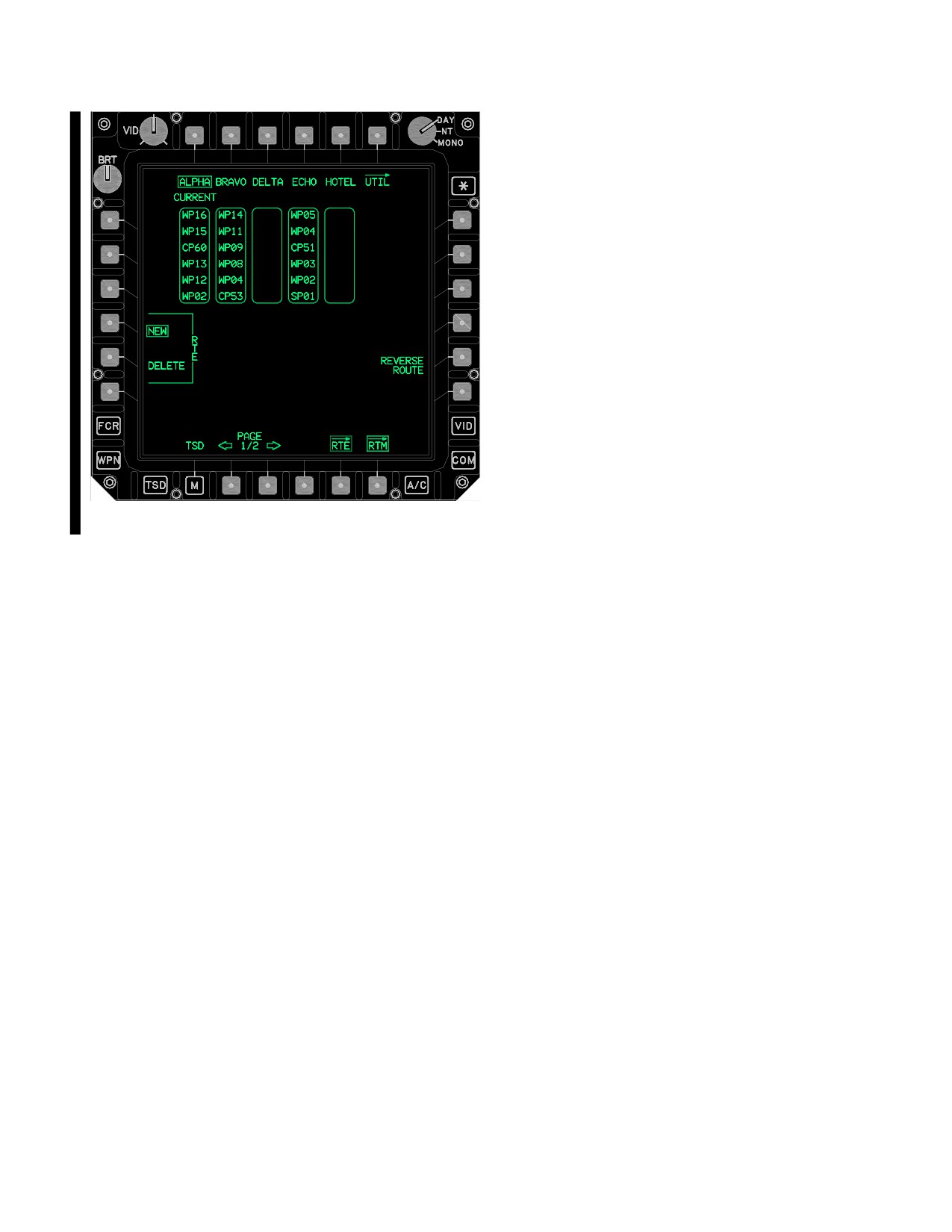
3A.91 ROUTE MENU (RTM) PAGE
to shift in order to display points along the route.
The RTM page (fig 3A-112) allows the crewmember to re-
3A.90.7 Route POINT Buttons. The route POINT
view stored route information, select a route for naviga-
number buttons provide the ability to review, add, delete,
tion, or delete a stored route. Two pages display a total of
or perform a direct route to a point in the current route.
ten stored routes. The NEW route button defaults to se-
The point label which represents the active destination is
lected upon display of the page.
Use or disclosure of this information is subject to the restriction(s) on the title page of this document.
3A-134
Change 2
TM 1-1520-251-10
file. The CURRENT label is displayed just above the se-
lected route window. Route name can only be entered
through the AMPS.
3A.91.2 RTE NEW Button. Selecting the RTE NEW
button allows the crewmember to designate a route as the
new current route for navigation.
3A.91.3 RTE DELETE Button. The RTE DELETE but-
ton allows the crewmember to permanently delete a route.
Once the RTE DELETE button is selected, selecting one
of the route name buttons calls up the delete route YES
and NO buttons.
a. RTE Delete YES Button. Selecting the delete
route YES button will cause the system to delete all the
points from the selected route. The coordinate data of the
points will remain in memory.
b. RTE Delete NO Button. Selecting the delete
route NO button will cause the system to abort the delete
route process.
LBA5046A
3A.91.4 REVERSE ROUTE Button. The REVERSE
ROUTE button allows the crewmember to reverse the
waypoint order in the current route. If the active point in
Figure
3A-112.
ROUTE MENU (RTM) Page
the current route is the first point, the new active point will
be set to the last point. If the active point is not the first, the
new active point will be set to the previous point. If a di-
The RTM page contains the following unique buttons:
rect - to point is the active point, the active point will not be
changed.
• T1 - T5
Route name buttons
• L4
RTE NEW button
3A.91.5 Route Status Windows. A route window is
displayed for each of the five routes presented on RTM
• L5
RTE DELETE button
page 1 or 2 to indicate the first 6 points within each route
• R5
REVERSE ROUTE button
and the route selected as the current route. A route win-
dow displays just below its associated route name button
3A.91.1 Route Name Buttons. The Route Name but-
in the upper area of the format. In addition, the CURRENT
tons provide the ability to select a particular route to be the
label displays just above the route window which is se-
current route for navigation or to be deleted from the route
lected as the current active route for navigation.
Use or disclosure of this information is subject to the restriction(s) on the title page of this document.
Change 3
3A-135
TM 1-1520-251-10
3A.92 COORDINATE (COORD) PAGE
• B4
Search (SRCH) button
• B5
FARM button
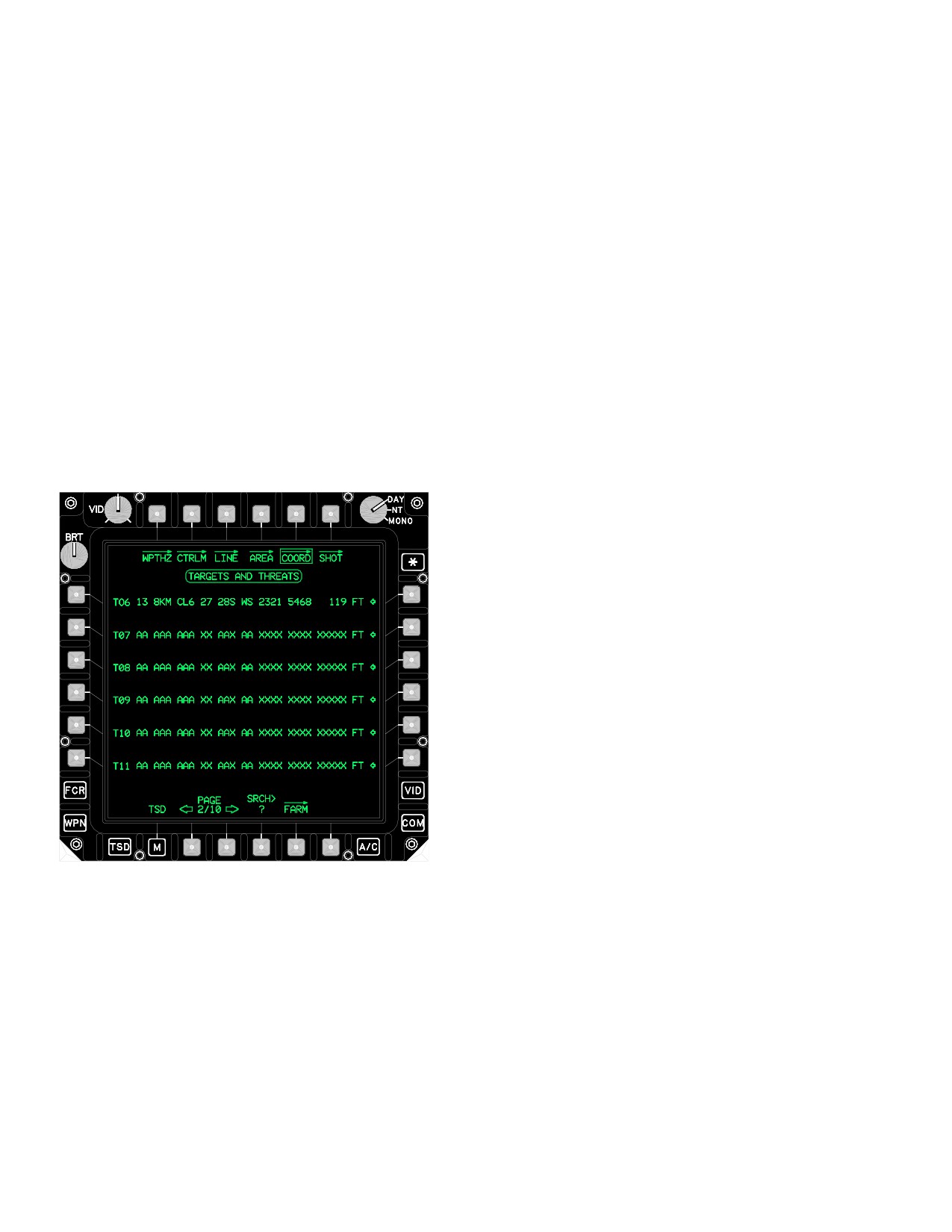
The target/threat COORD page (fig 3A-113) provides access
to coordinate file data. The COORD page contains the com-
3A.92.1 Waypoint/Hazard
(WPTHZ) Page But-
plete coordinate data file of stored targets and threats. The
ton. Selection of the WPTHZ button will cause the way-
COORD page also provides the ability to select a target or
point/hazard page to be displayed.
threat as the acquisition option or to expand the display of de-
tailed target or threat information for review. The system shall
3A.92.2 Control Measures
(CTRLM) Page But-
initialize to the first page unless the current acquisition source
ton. Selection of the CTRLM button will cause the con-
(T##) is a target or threat. If the crew attempts to add or store
trol measures page to be displayed.
more than 50 targets or threats, the system overwrites the
target or threat starting one location past the end of the target
3A.92.3 LINE Page Button. Selection of the LINE but-
and threat safe set. The target and threat file has up to 25
ton will cause the LINE page to be displayed.
locations protected from overwriting referred to as the safe
set. The SP protects all targets, up to 25, that are loaded from
3A.92.4 AREA Page Button. Selection of the AREA
the DTC. The crew can edit these protected files, but they will
button will cause the AREA page to be displayed.
not be overwritten. The SP will only use these protected loca-
tions for storing if the target or threat that was initially loaded
3A.92.5 Shot-At (SHOT) Page Button. Selection of the
in that location has previously been deleted.
SHOT button will cause the Shot-At page to be displayed.
3A.92.6 Target/Threat Coordinate Acquisition Selection
Buttons. The COORD acquisition select buttons rapidly
select a target or threat from the file as an acquisition source.
3A.92.7 Target/Threat Coordinate Expansion But-
tons. Selection of the COORD expansion buttons expands
the single line of target or threat information into three lines of
information. The single line of target or threat information con-
tains the following:
• Target/Threat type and number
• Target/Threat identifier
• Free text identifier
• Spheroid
• Datum
• UTM coordinates
• MSL elevation
The expanded three lines of information contain the fol-
LBA2546A
lowing additional information:
• Estimated Time Enroute (ETE)
Figure
3A-113.
COORD Page
• Estimated Time of Arrival (ETA)
• T1
WPTHZ button
• Bearing
• T2
CTRLM button
• Distance to go (Km)
• T3
LINE button
• Latitude/Longitude coordinates
• T4
AREA button
• Distance to go (NM)
• T6
SHOT button
• L1 -L6
Acquisition Selection buttons
When an expansion button is selected it will automatically
• R1 - R6 Point Expansion buttons
deselect any other previously selected expansion button.
Use or disclosure of this information is subject to the restriction(s) on the title page of this document.
3A-136
Change 2
TM 1-1520-251-10
3A.92.8 Target/Threat Coordinate Search (SRCH)
The selections made from the WPTHZ page are identical
Button. The target/threat coordinate SRCH button pro-
to the selections made on the COORD page except that
vides the ability to rapidly search within the target/threat
when selecting an acquisition select button, the acquisi-
coordinate data file.
tion source will change to a waypoint or hazard instead of
a target or threat.
3A.92.9 Fuel, Ammo, Rockets, and Missiles (FARM)
3A.94 CONTROL MEASURE (CTRLM) PAGE
Button. Selecting the FARM button displays the FARM
page.
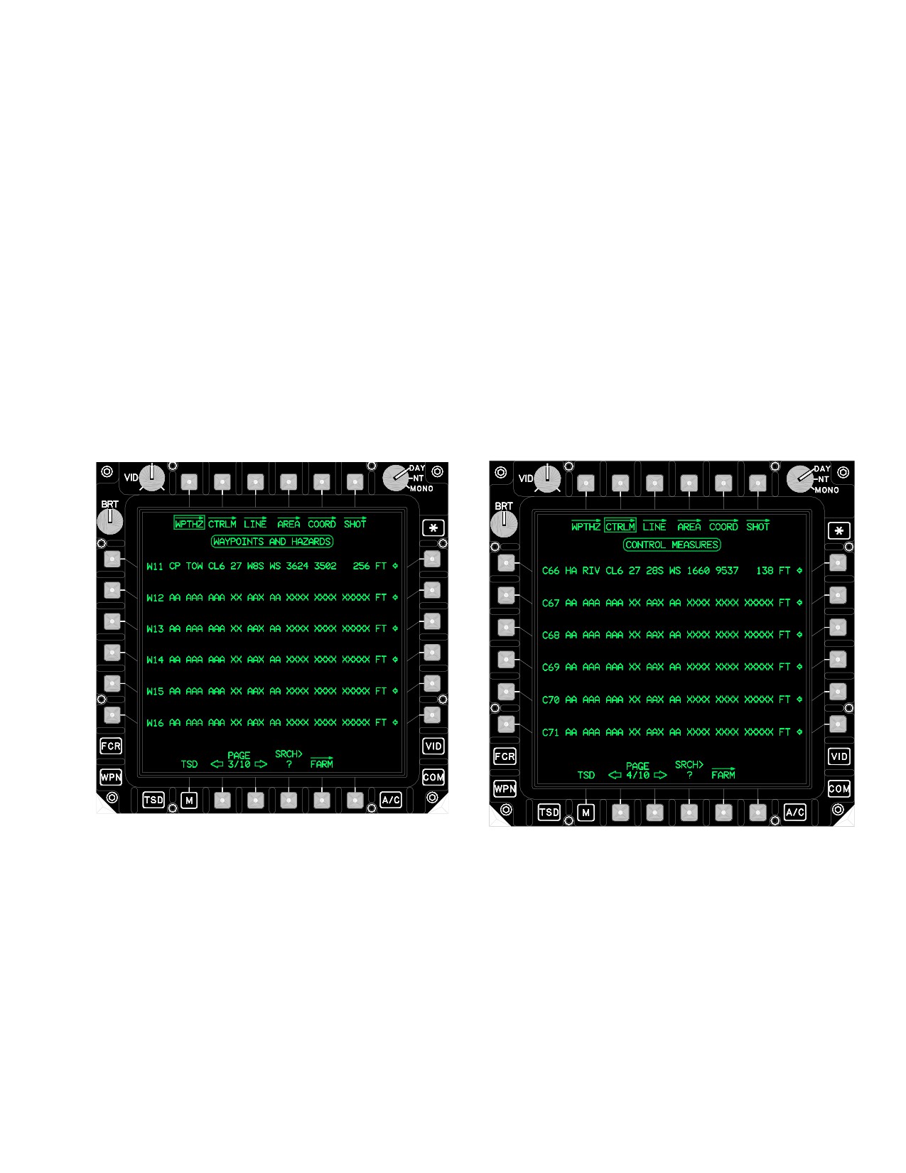
The CTRLM page (fig 3A-115) accesses the coordinate file
data of control measures. The CTRLM page allows for the
3A.93 WAYPOINT/HAZARD (WPTHZ) PAGE
selection of a control measure as the acquisition option or to
expand the display of detailed control measure information
The WPTHZ page (fig 3A-114) accesses the coordinate
for review. The system initializes to the first page unless the
file data of waypoints and hazards. The WPTHZ page al-
current acquisition source (T##) is a control measure. The
lows for the selection of a waypoint or hazard as the ac-
selections made from the CTRLM page are identical to the
quisition option or to expand the display of detailed way-
selections made on the COORD page except for the follow-
point or hazard information for review. The system
ing: When selecting acquisition select button, the acquisition
initializes to the first page unless the current acquisition
source will change to a control measure instead of a target or
source (T##) is a waypoint or hazard.
threat. The SRCH button has a valid range of 51 to 99.
LBA1930A
LBA5032
Figure 3A-114. WAYPOINTS and HAZARDS Page
Figure 3A-115. CONTROL MEASURES Page
Use or disclosure of this information is subject to the restriction(s) on the title page of this document.
Change 2
3A-137
TM 1-1520-251-10
3A.95 LINE PAGE
(maximum) areas stored in the navigation data base. The
system initializes to the first page. The AREA page is
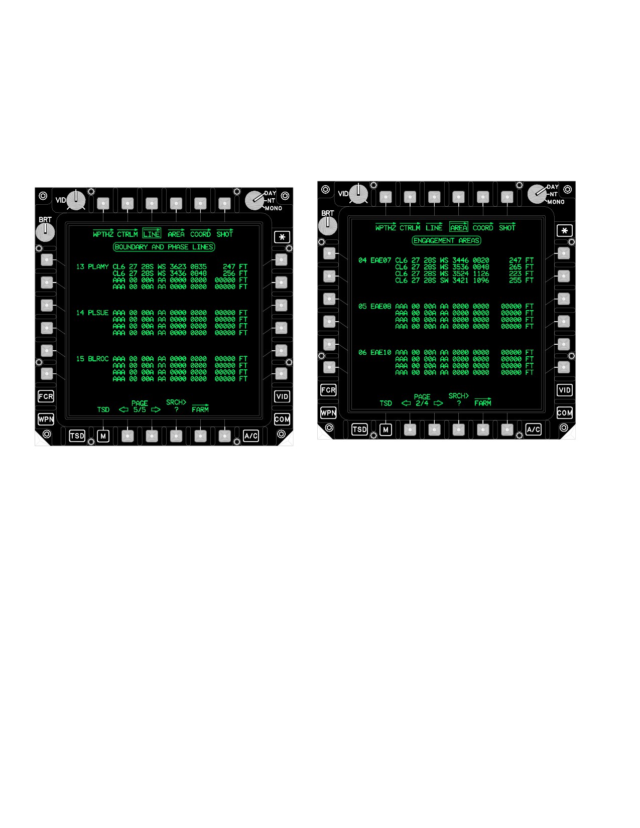
The LINE page (fig 3A-116) provides the ability to view the
identical to the LINE page such that the page is for view-
coordinates associated with each of the 15 (maximum)
ing only. One difference between the lines and areas is
boundary and phase lines stored in the navigation data
that each area must be made up of four points. The AREA
base. The system initializes to the first page. The LINE
data display area lists the data stored for each area in the
data display area lists the data stored for each line in the
file.
file. Each line may consist of between two and four points.
LBA5044
LBA5045
Figure 3A-116. LINE Page
Figure 3A-117. AREA Page
The list includes the following information:
The list includes all four points defining the area and in-
• Line file number
cludes the following information:
• Line identifier
• AREA file number
• UTM coordinate for each point
• AREA identifier
• MSL altitude for each point
• Spheroid
• Datum
3A.96 AREA PAGE
• UTM coordinate for each point
The AREA page shown in (fig 3A-117) provides the ability
to view the coordinates associated with each of the 12
• MSL altitude for each point
Use or disclosure of this information is subject to the restriction(s) on the title page of this document.
3A-138
Change 2
TM 1-1520-251-10
3A.97 SHOT PAGE
The SHOT page contains the following unique buttons:
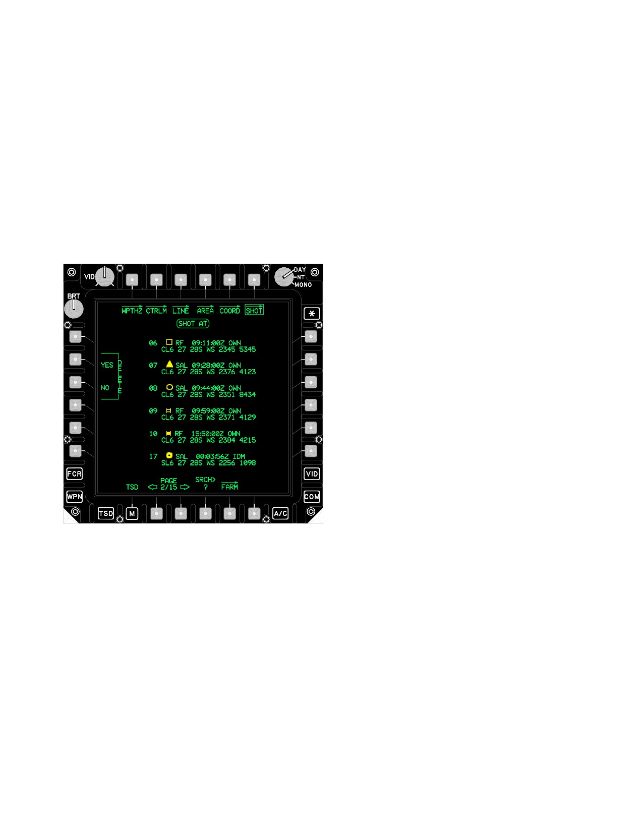
The SHOT page, shown in (fig 3A-118) accesses the
coordinate file data of shot-at locations stored in the navi-
• L3
DEL button
gation data base. This file is capable of storing up to 128
shot-at locations on 26 display pages of 6 points per page.
The file is split into 2 parts. The first 16 locations are re-
3A.97.1 Delete (DEL) Button. The DEL buttons allows
served for targets shot-at by the ownship. The last 112
the crew to delete all shot-at location coordinate points
locations are reserved for targets shot-at by other aircraft.
received from other aircraft. Selecting the DEL button
If more that 16 targets are shot-at by the ownship, the sys-
calls up the Delete Shot YES and Delete Shot NO buttons.
tem will overwrite shot-at locations beginning with the first
position in the file. If more than 112 shot-at locations are
added to the file, the system will overwrite the shot-at
locations beginning with the 17th position in the file.
3A.97.2 SHOT-AT Data Display Area. The SHOT-AT
data display area lists the data stored for each shot-at in
the file. The display area includes the following informa-
tion:
• Shot-at file number
• Target symbol
• Missile type
• Zulu Time of trigger pull
• OWN or IDM indication
• Spheroid
• Datum
LBA5043
Figure 3A-118. SHOT Page
• UTM coordinate of Shot-at (para 3.62.16)
Use or disclosure of this information is subject to the restriction(s) on the title page of this document.
Change 2
3A-139

TM 1-1520-251-10
3A.98 FUEL, AMMO, ROCKETS, AND MISSILES
NOTE
(FARM) PAGE
• If a system is turned off the message will
indicate its information is not available.
• If the aircraft is in simulation mode, the
The FARM page (fig 3A-119) allows the crew to quickly re-
simulated inventory will be sent.
view FARM reports. Selecting the FARM button will display
data from the last seven received FARM reports. However, if
• If the aircraft is configured for TESS and
a FARM report is received and the call sign matches a FARM
has detected any live ordinance the gun
report currently in the system, the FARM report will be over-
quantity present, rocket launcher present,
written. If a FARM report is received and the call sign does
and HELLFIRE launcher present will indi-
not match an existing FARM report it will be written to the
cate not present in the message. The mes-
next available location. If a location is not available, the oldest
sage will indicate the gun, rocket, and
FARM report will be overwritten.
HELLFIRE quantities are not available.
• If equipment failure occurs (or hang fires)
those quantities will not be included in the
The TYPE button allows the crew to determine what type
message.
of FARM report data is displayed PP, EXPEN, MSL or BA-
SIC. The reports are sorted from the newest to oldest
• If data is invalid or no launchers are pres-
based on date/time (then by call sign).
ent, “NA” will be displayed in the ap-
propriate column on the page.
a. BASIC Button. Displays basic FARM data (fig
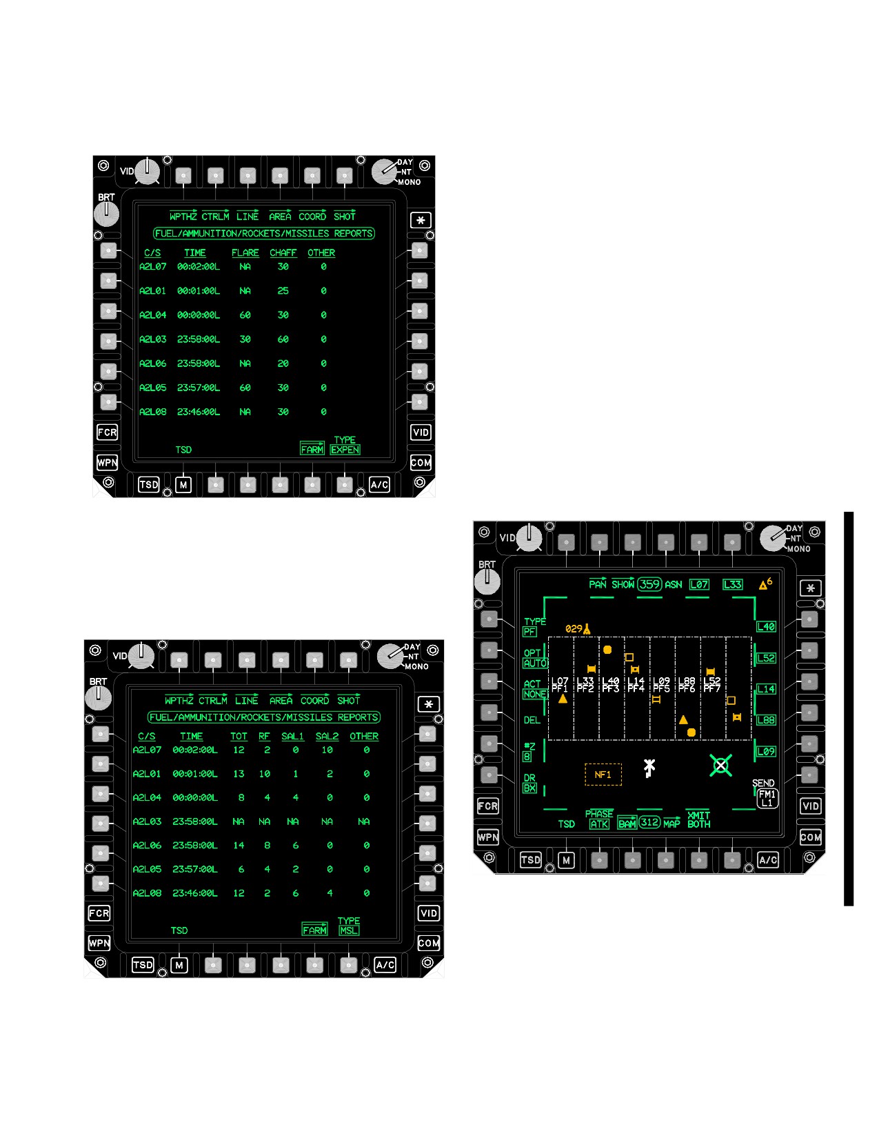
3A-120). The SAL column on this page displays the sum
of SAL1 and SAL2 missiles.
LBA5006
LBA5007
Figure 3A-119. FARM Page
Figure 3A-120. BASIC FARM Data
Use or disclosure of this information is subject to the restriction(s) on the title page of this document.
3A-140
Change 2
TM 1-1520-251-10
b. EXPEN Button. Displays all ASE Expendables
3A.99 BATTLE AREA MANAGEMENT (BAM) PAGE
(fig 3A-121).
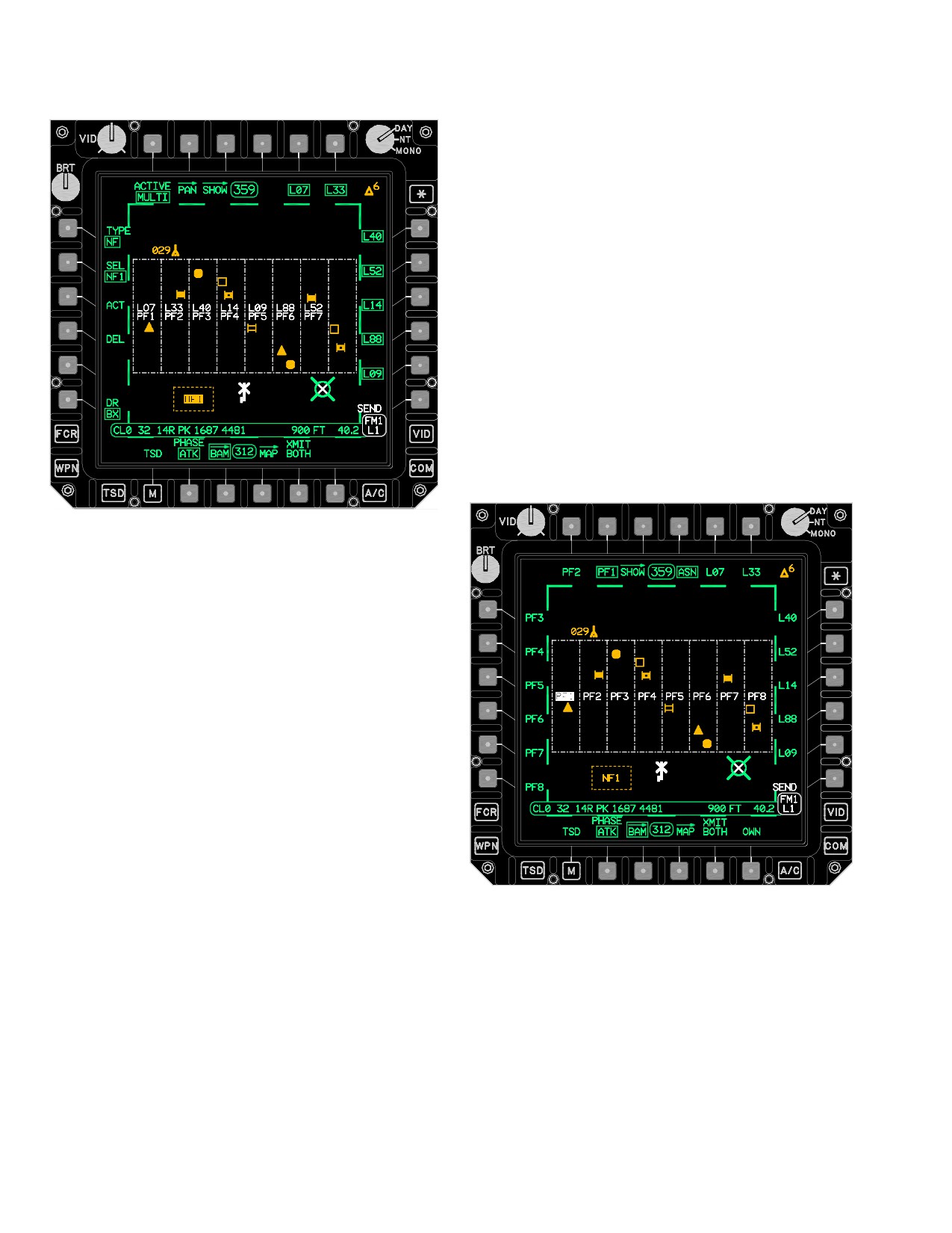
The BAM page ( fig 3A-123, or fig 3A-124) is displayed in the
NAV or ATTACK phases. Selecting the BAM page will freeze
the TSD. The BAM page provides the ability to construct and
assign priority fire and no fire zones for the battle manage-
ment mission segment. A maximum of 8 priority fire zones
and 8 no fire zones can be displayed on the TSD. A maxi-
mum of 1 priority fire zone and up to 8 no fire zones can be
active at any time. Active PFZ and NFZ’s will marquee to aid
the crew in determining which of the zones are active. The
active priority fire and no fire zones affect the prioritization on
the next scan after the zone has been created, received, or
reassigned. FCR targets detected within an active priority fire
zone out-prioritize the FCR targets which fall outside the
zone. FCR targets detected within the active no fire zones
are not prioritized.
LBA5009
Figure 3A-121. EXPEN FARM Data
c. MSL Button. Displays specific Hellfire missile
counts (fig 3A-122). “Other” is the difference between the to-
tal missile count and sum of the RF, SAL1, and SAL2 counts.
LBA5042A
LBA5010
Figure 3A-123. BATTLE AREA MANAGEMENT
Figure 3A-122. MSL FARM Data
(BAM) Page, Type PF
Use or disclosure of this information is subject to the restriction(s) on the title page of this document.
Change 3
3A-141
TM 1-1520-251-10
3A.99.1 Active (ACT) Button. The ACT button allows
for selection of an active priority fire zone and/or active no
fire zones. The system displays the ACT button only when
fire zones are loaded into the system. When the ACTIVE
button is set to MULTI, each no fire zone can be individu-
ally activated or deactivated using the ACT button. When
a no fire zone is being deactivated and it is the current
single active no fire zone, the first no fire zone that is
found to be active starting from NFZ1 will be selected as
the single active no fire zone for the IDM transmission.
3A.99.2 Assign (ASN) Button. Selecting the ASN but-
ton commands the system to display the Priority Fire Zone
Identifier buttons and make the Subscriber Identifier and
OWN buttons available for selection, (fig 3A-125). The
ASN button is displayed whenever priority fire zones are
present in the system or all the points for the zones being
created have been entered.
LBA5041A
Figure 3A-124. BATTLE AREA MANAGEMENT
(BAM) Page, Type NF
The BAM page contains the following buttons:
• T1
ACTIVE Button
• T4
ASN Button
• T5/6
Subscriber Buttons
• L1
TYPE Button
• L2
OPT Button
• L3
ACT Button
• L4
DEL Button
• L5
#Z Button
• L6
DR Button
• R1 - R5 Subscriber Buttons
• R6
SEND Button
LBA5040A
• B2
CLR Button
• B5
XMIT BOTH Button
• B6
OWN Button
Figure 3A-125. Assign (ASN) Button Selected
Use or disclosure of this information is subject to the restriction(s) on the title page of this document.
3A-142
Change 2
TM 1-1520-251-10
3A.99.3 TYPE Button. The TYPE button allows the
c. Target Reference Point (TRP) Button. Selec-
crew to toggle between Priority Fire (PF) and No Fire (NF)
tion of the TRP button enables the cursor to select a point
zone controls (fig 3A-123).
on the map as the center of the priority fire zones to
create. The size of the zones is based on the setting of the
3A.99.4 Option (OPT) Button. The OPT button is dis-
kilometer KM button. When the crew has selected the ref-
played when the TYPE is PF, and allows the crew to select
erence point, the ASN, CLR and SEND buttons will be
the AUTO, MAN or TRP drawing method. AUTO is the de-
displayed.
fault.
(1) Kilometer (KM) Button. The KM (kilometer)
a. Automatic (AUTO) Button. Selection of the
button displays when the TRP button is selected. Select-
AUTO button enables the cursor control to select four
ing the KM (kilometer) button allows the crew to select the
points which connect to form a quadrilateral polygon. Se-
size (1 - 3 km) of the TRP PFZ. The zone size is measured
lecting the fourth corner of the polygon divides the poly-
in terms of the length of one side of the square box for
gon into a number of priority fire zones 1 - 8, as determined
each of the four zones. The default size is 2 km.
by the current value of the #Z button. When the crewmem-
ber has selected the first point the CLR button will be dis-
3A.99.5 Number (#Z) Button. Selecting the #Z
played. When the crewmember has selected the last
(1 - 8) button allows the crew to select the number of zones
point, the ASN and SEND buttons will be displayed.
to be created. The number of the zones to be created de-
Selection of the OPT button removes all of the existing
faults to the number of zone members designated plus
priority fire zones from the MPD in preparation of drawing
one for the ownship.
a new PFZ.
3A.99.6 Draw (DR) Button. Selecting the MAN or
b. Manual (MAN) Button. Selection of the MAN
AUTO button calls up the DR button, which toggles be-
button enables the cursor to select points for each zone
tween BX (box) and LN (line) modes of the cursor opera-
that will be created based on the current setting of the #Z
tion. The box mode allows the crew to select two opposite
button. When the crewmember has selected the first point
corners of a box for PF/NF zone construction. The LN
the CLR button will be displayed. When the crew has se-
mode allows the operator a quadrilateral polygon for a PF/
lected the last point of the last priority fire zone, the ASN
NF zone. Using the LN method to draw, the zones will be
and SEND buttons will be displayed.
oriented parallel to the first line drawn.
Use or disclosure of this information is subject to the restriction(s) on the title page of this document.
Change 3
3A-143
TM 1-1520-251-10
3A.99.7 SELECT (SEL) Button. When the TYPE is NF,
3A.99.10 ACTIVE Button. When the TYPE is NF, the
the SEL button allows the crew to select the NF zone to
ACTIVE button allows the crew to switch between MUL-
modify (fig 3A-124). Each active NFZ is indicated by an
TI(ple) and SINGLE mode. When in MULTI active mode,
arrow. Empty zones (undrawn) are WHITE with a question
more than one no fire zone can be active at the same
mark next to the number.
time. When in SINGLE active mode, only one no fire zone
can be active at one time. If another no fire zone is active
NOTE
at the time a no fire zone is activated, it will automatically
• Instead of selecting the ACT or ACCEPT
be deactivated. When the FCR is powered on, the AC-
buttons, the crew may begin drawing the
TIVE button will be barriered and the DP will automatically
next no fire zone and the previously drawn
mode to either MULTI or SINGLE based on the capability
zone will automatically be accepted.
of the FCR.
• The DP will keep track of all the active no
fire zones and the single active no fire zone
when the ACTIVE button is set to MULTI for
3A.99.11 Subscriber Identifier Buttons. To assign in-
backwards compatibility. This will allow the
dividual priority fire zones to each subscriber, the crew will
receiving DP to use the appropriate data,
select the subscriber buttons in the desired sequence. In
either multiple active no fire zones or a
turn, the system assigns PF1 to the first subscriber se-
single active no fire zone based on the re-
lected, PF2 to the second subscriber selected, and so
ceiving aircraft current capability.
forth, until all assignments are completed. The crew may
• Both the DP and the FCR will automatically
also deselect the subscriber identifier buttons to remove
configure to the capability of the other. This
the subscriber from the selected priority fire zone.
will allow an FCR with single active no fire
zone capability to be installed with a DP
with multiple active no fire zone capability or
vice-versa with no impact other than the
3A.99.12 SEND Button. Selecting the SEND button
functional differences between multiple and
transmits the priority fire zones to the selected zone mem-
single active no fire zone.
bers on the IDM net. The SEND button will be displayed
when the last point of the priority fire zones or no fire
3A.99.8 ACCEPT Button. The ACCEPT button allows
zone,being created has been entered. The XMIT BOTH
the crew to accept a NFZ permanently if all the points for
button will determine if both the PF and NF zones are
the new NFZ have been entered.
transmitted or only the current type of zone determined by
the TYPE button are transmitted.
3A.99.9 DELETE (DEL) Button. The DEL button al-
lows the crew to delete all Priority Fire zones or each No
Fire zone individually. Crew has YES/NO option.
3A.99.13 Clear (CLR) Button. The CLR button clears
NOTE
the last cursor entry for the polygon in progress. Subse-
Although the IDM messages will support
quent selections will remove the next to last cursor entry
sending data between differently configured
and so on.
aircraft (i.e., some single active no fire zone
and some multiple active no fire zones) it is
advised that aircraft communicating be set
to the same active mode (if possible) to
3A.99.14 XMIT BOTH Button. Selecting the XMIT
avoid data being ignored due to different
BOTH button allows the crew to select/deselect sending
modes of operation.
both PF and NF zones when SEND is selected.
Use or disclosure of this information is subject to the restriction(s) on the title page of this document.
3A-144
Change 3
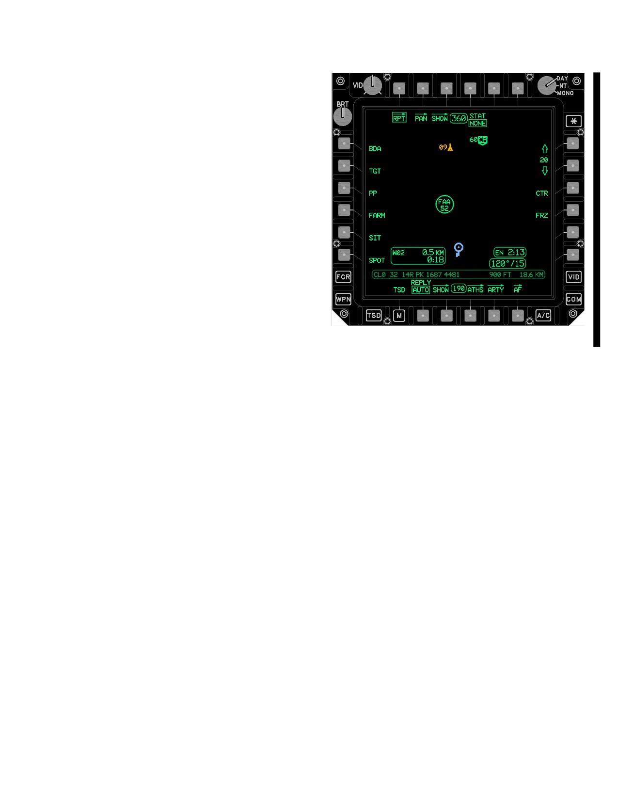
TM 1-1520-251-10
3A.99.15 OWN Button. The crew selects the OWN
button to assign the selected priority fire zone to the own-
ship. The system displays the word OWN in the center of
the priority fire zone assigned to the ownship.
3A.99.16 Priority Fire Zones. A maximum of 8 priority
fire zones can be created/displayed on the TSD. Only the
active priority fire zone is displayed in WHITE full intensity.
The inactive priority fire zones are displayed partial inten-
sity. The active PFZ will marquee on the TSD and FCR
pages. The label for the PZF will be removed to allow the
crew to easily identify the highest priority targets. The Ac-
tive priority fire zone will be displayed in both GTM and
ATM mode on the FCR Page.
3A.99.17 No Fire Zones. Eight no fire zones can be
created/displayed on the TSD. No fire zones are dis-
played in full intensity in YELLOW. The active no fire
zones will marquee on the TSD and FCR pages.
3A.100 REPORT (RPT) PAGE
LBA5035A
The RPT page (fig 3A-128) provides the ability to send re-
Figure 3A-128. RPT Page
ports using the IDM to network primary members, or to
query those members for the selected report. The RPT
page contains the following unique buttons:
3A.100.1
STAT Button. Selecting the STAT button
calls up the NONE, MTO, AFM, SPOT and SIT buttons.
• T4
STAT button
The default selection is NONE, or the last option selected
for which a corrresponding closure STATUS window is
• T5 - T6
Subscriber buttons
displayed.
• L1
BDA button
a. NONE Button. Selecting the NONE button
• L2
TGT button
closes any currently displayed closeable status window.
• L3
PP button
b. MTO Button. Selecting the MTO button causes
• L4
FARM button
display of the message to obsesrver status window.
• L5
SIT button
c. AFM Button. Selecting the AFM button causes
• L6
SPOT button
display of the Airfire Mission Status window.
• R1 - R5 Subscriber buttons
d. SPOT Button. Selecting the SPOT button
• B2
REPLY/MSG button
causes display of the SPOT Report status window.
• B5
ARTY Page button
e. SIT Button. Selecting the SIT button causes dis-
• B6
AF Page button
play of the Situation Report Status WIndow.
Use or disclosure of this information is subject to the restriction(s) on the title page of this document.
Change 3
3A-145
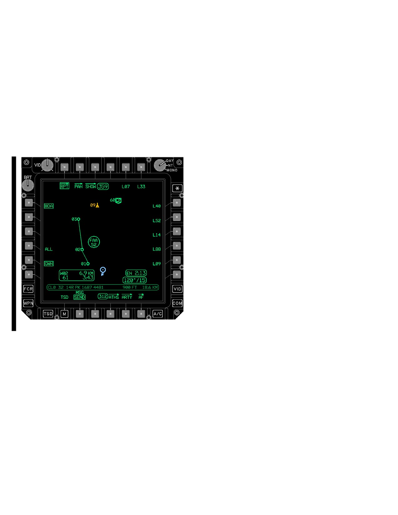
TM 1-1520-251-10
3A.100.2 Battle Damage Assessment (BDA) But-
c. Selecting Individual FCR Targets. If neither the
ton. Selecting the BDA button (fig 3A-129) calls up the
ALL nor the PRI button is selected, the crew can select
ALL and OWN buttons. The OWN button is default se-
individual FCR target(s) that the system will transmit out
lected.
when the crew selects the SEND button.
a. ALL BDA Button. Selecting the ALL button
3A.100.4 Present Position (PP) Report Button. Se-
instructs the system to transmit all of the BDA reports over
lecting the PP button commands the system to transmit or
a radio with Longbow protocol selected when the crew se-
request out the aircraft present position when the crew se-
lects the SEND button.
lects the SEND button. The PP report works with Long-
bow, Tactical internet, and Fire Support protocols.
b. OWN BDA Button. Selecting the OWN button
instructs the system to transmit or request BDA reports for
the ownship when the crew selects the SEND button.
3A.100.5 Fuel, Ammo, Rockets, and Missiles (FARM)
Button. Selecting the FARM button commands the sys-
tem to transmit or request a FARM report when the crew
selects the SEND button. The FARM report only works
with the Longbow protocol.
a. The following data will be transmitted to or re-
quested from all selected subscribers when the crew se-
lects the SEND button.
• Call Sign (5 characters)
• Date (month, day, and year)
• Present Position (Lat/Long)
• Elevation (feet)
• Fuel Quantity (Lbs)
• Gun rounds present and quantity
• Rockets (launcher present and quantity)
LBA5038A
• Hellfire missiles (quantity of SAL 1, SAL 2, and RF)
Figure
3A-129.
Page Layout When BDA Is Selected
• Quantity of all ASE Expendables
3A.100.3 FCR Targets (TGT) Button. Selecting the
3A.100.6 Situation (SIT) Report Button. Selecting the
TGT button calls up the ALL and PRI (Priority) buttons,
SIT button calls up the MISSION and OP NATURE but-
and enables the cursor to select individual FCR target(s).
tons. The SIT report is issued when the crew selects the
FCR targets can only be sent, they can not be requested.
SEND button. The situation report provides the recipient
with the aircraft location, fuel type and quantity, and weap-
a. ALL FCR Targets Button. Selecting the ALL
ons inventory. Weapons load is actual inventory if tactical
button instructs the system to transmit all FCR targets
weapons are on board, and simulated inventory if operat-
(high and low priority) when the crewmember selects the
ing in TESS mode.
SEND button.
b. Priority (PRI) FCR Targets Button. Selecting
a. MISSION Button. Selecting the MISSION button
the PRI button instructs the system to transmit only high-
instructs the system to indicate whether or not the crew
priority FCR targets (up to 16) when the crew selects the
can accomplish the current mission. The options are;
SEND button.
WILL COMPLY or CAN’T COMPLY.
Use or disclosure of this information is subject to the restriction(s) on the title page of this document.
3A-146
Change 3
TM 1-1520-251-10
b. OP NATURE Button. The OP NATURE multi -
(2) TGT/THRT Selection. When REPORT is set
state button is used to select the operational nature of the
to TGT/THRT, additional controls are displayed for inclu-
aircraft at the time of the SITREP report. Selecting the OP
sion in the SPOT report. The TGT/THRT report is used to
NATURE button enables the crew to select from a variety
send a single TGT/THRT or Control Measure file.
of options including;
(3) TGT/THRT Status Window. The TGT/THRT
• BATTLE H.O. (Hand Over)
status window is displayed when report is set to TGT/
• MOVE
THRT. The status window displays the data entered by the
crewmember that will be sent in the SPOT report. Informa-
• MOVE TO CONTACT
tion includes: Target number (e.g. T01), Quantity, Course
and Speed.
• ATTACK
• ZONE RECON
c. THRT Button. The THRT button is used to
• ROUTE RECON
manually enter data pertaining to the SPOT report for the
report. When a target/threat is cursor - selected, or a tar-
• AREA RECON
get/threat number is entered, the crewmember will be
• SCREEN
prompted to add the following data using the KU:
• FARP
• Target Number
• Quantity
3A.100.7 SPOT Report Button. The SPOT report but-
• Course (in degrees)
ton is used to send a SPOT report. Selecting the SPOT but-
ton will call additional selections to be sent with the SPOT re-
• Speed (in knots)
port. The SPOT report is used to issue a target handover
d. TARGET Button. The TARGET button is used to
based on an FCR scan or a selected target/threat file.
select a target type for the SPOT report. Selecting the TAR-
GET button will display the grouped options including:
a. ALLIANCE Button. The ALLIANCE button is
• APC
used to indicate the target alliance. Selecting the AL-
LIANCE button displays the selections; FRIENDLY, UN-
• TANK
KNOWN, and HOSTILE. The crewmember can then se-
• TRUCK
lect the target alliance. The default selection for
• ARTY
ALLIANCE is UNKNOWN.
• BRIDGE
b. REPORT Button. The REPORT two - state but-
• BUILDING
ton is used to establish the type of spot report being sent.
• ASMBLY AREA
Selecting the REPORT button will toggle between PRI
• TROOPS
FCR and TGT/THRT. PRI FCR is the default selection.
• ADU
(1) PRI FCR Selection. When REPORT is set to
• AIRCRAFT
PRI FCR, the SPOT report is sent based on the last FCR
scan conducted with up to 16 targets sent. If no FCR tar-
e. ENEMY ACT (Activity) Button. The ENEMY
gets are detected, a crewmember must set the REPORT
ACT button is used to establish the activity of the enemy
button to TGT/THRT and select a target/threat file, or the
unit for the SPOT report. Selecting the ENEMY ACT but-
SEND button will not display.
ton displays the ENEMY ACT grouped options including:
• STATIONARY
NOTE
• ASSEMBLING
When the REPORT button is set to PRI
• RIVER XING
FCR, the SPOT report should not be used to
• NO ACTIVITY
send from one Longbow aircraft to another.
• DEFENDING
If more than 14 priority FCR targets exist,
the IDM may lock - up during transmission.
• WITHDRAWING
Use or disclosure of this information is subject to the restriction(s) on the title page of this document.
Change 2
3A-147
TM 1-1520-251-10
3A.100.8 Subscriber Buttons. The subscriber buttons
3A.100.10 Artillery (ARTY) Page. The ARTY page (fig
are used to select intended message recipients. Default is all
3A-130) provides the ability to send data messages to the
subscribers selected for the TGT, PP, and FARM and none
primary Fire Support Element (FSE) member of the se-
selected for BDA, SPOT, and SIT.
lected artillery net. Tactical AFAPD and JVMF messages
can also be received from this page. The ARTY page
3A.100.9 3.82.6 RPLY/MSG (Reply/Message) but-
button is only accessed from the RPT or AF page, and
ton. The RPLY/MSG button is used to select whether or
contains the following unique buttons:
not the ownship replies automatically to a request or not,
and establishes whether an outgoing message is a re-
Figure 3A-130. ARTY Page
quest for information or is actually sending ownship infor-
mation.
• T5
Primary Subscriber button
• L1
MSG button
NOTE
• L3
TARGET button (CFF)
The FARM QUERY message must be
• L3
CHECK ALL button (ABORT)
manually replied to.
•
L4
QTY button (CFF)
a. RPLY (Reply) Button. The RPLY button is dis-
• L4
SITREP button (ABORT)
played when no report types (e.g. BDA) are selected. The
• L5
CONTROL button
button determines if the ownship will automatically re-
(CFF/REPEAT/ADJUST)
spond to queries for AFAPD, PP and BDA reports. It
• L5
SPOT button (ABORT)
toggles between AUTO and OFF.
•
L5
TARGET button (CHK FIRE)
b. MSG Button. The MSG button displays once
• L6
DANGER CLOSE button
one of the following reports is selected; BDA, PP, or
(CFF/REPEAT/ADJUST)
FARM. The MSG button is used to select whether the re-
• L6
EFFECT button (EOM/SURV)
port is being sent or a request is being made. The MSG
• L6
ARTY MISSION button (ABORT)
button toggles between SEND and RQST with SEND as
default.
• R5
NONE button
Use or disclosure of this information is subject to the restriction(s) on the title page of this document.
3A-148
Change 4
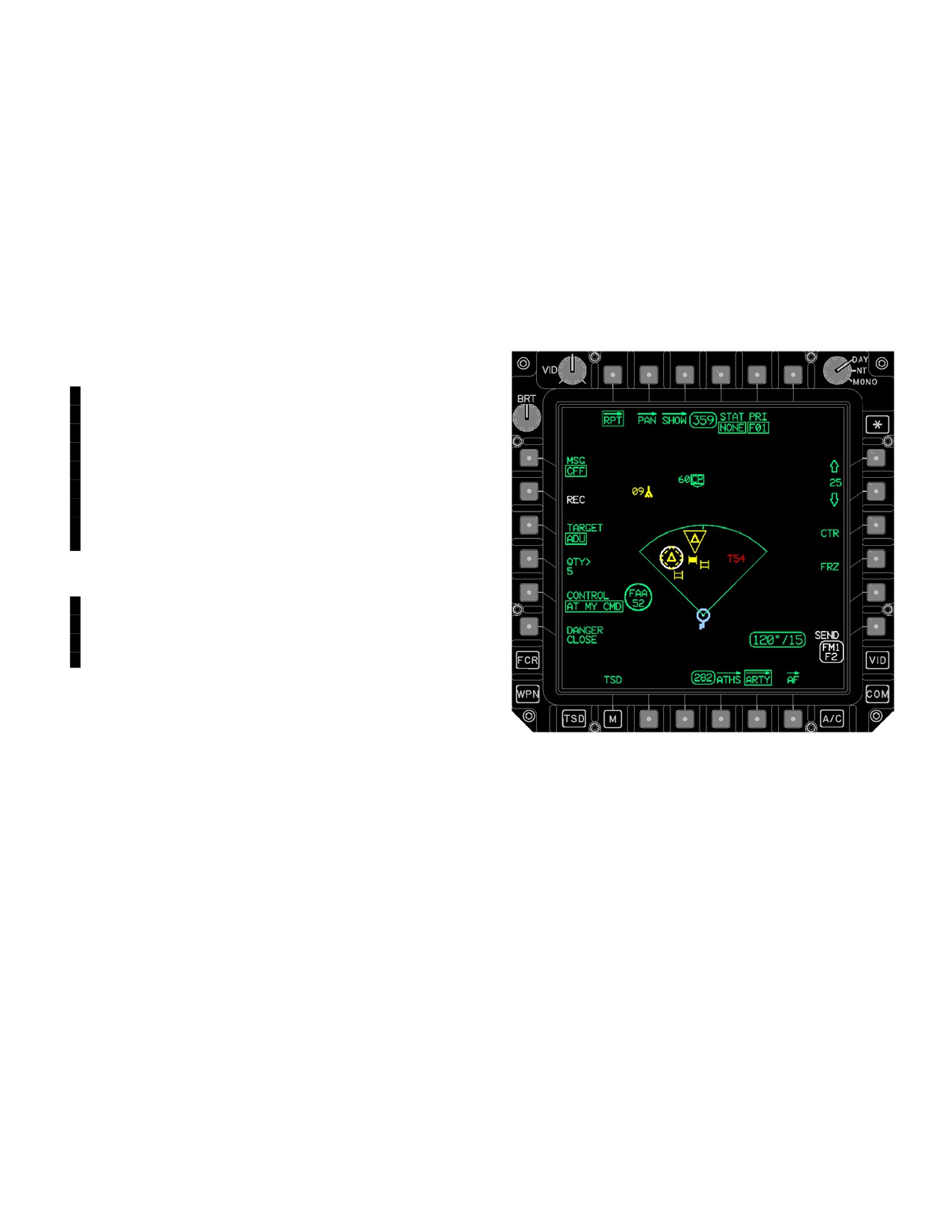
TM 1-1520-251-10
3A.100.11 Primary Subscriber Button. The PRIMA-
NOTE
RY SUBSCRIBER button is displayed when a primary
Dynamic time of flight assumes that rounds
subscriber has been assigned to the fire support net, and
were fired at time a SHOT update was re-
indicates the call sign of the primary subscriber. Artillery
ceived (stored) in the aircraft.
mission messages sent via the ARTY page are intended
for the FSE only, therefore only the single subscriber is
c. Call For Fire (CFF) Button. Target selection de-
presented.
faults to the FCR NTS when CFF (ref 3A-131) is selected.
3A.100.12 MSG Button. The message multi - state but-
The crewmember can cursor select a target or FCR targ-
ton is used to select what type of message is being sent or
set for the CFF message. The CFF icon is displayed over
to abort out of a message thread. Selecting the MSG but-
the NTS symbol or the target selected by the crewmem-
ton displays the MESSAGE grouped options for selection
ber.
of message type. Based on the message type selected
additional selections will be displayed on the ARTY page.
The message options include:
a. CHK FIRE (Check Fire) Selection. The CHK
FIRE selection (fig 3A-130) is used to send a Check Fire
message to the Fire Support Net. There are two selec-
tions available for a check fire message and are selected
using the TARGET button. Whenever a CHK FIRE ALL or
by TARGET is sent by the platform the STAT LAST will au-
tomatically be displayed to provide the operator with the
capability to view the operator response once it is recei-
ved.
NOTE
Check fire enables interface to prevent di-
recting further fires on target, however, it is
important to back this up with a radio call
anytime that an operator ack is not received
(1) TARGET Button. The TARGET button is
used to select the parameters of a check fire. The TARGET
button toggles between ALL and SINGLE. The default selec-
tion is ALL, if no CFF mission is in progress, otherwise the
LBA5038A
default is set to SINGLE. When ALL is effected all active
CFF within the Fire Support Net are ceased. When SINGLE
Figure
3A-131.
ARTY Page with CFF
is effected, only the CFF sent from the ownship is ceased.
NOTE
(1) TARGET Button. The TARGET button is
used to designate the type of target(s) in the CFF mes-
• Only one ARTY mission can be selected
sage. TARGET is barriered if a CFF mission from ownship
at any given time.
is active. Target selections available include:
• The target number is provided in the
• APC
MTO (message to observer), and is re-
• TANK
quired to process any subsequent trans-
• TRUCK
mit or receive messages in the mission.
Many buttons may be barriered or not
• ARTY
displayed if a valid MTO has not been
• HARD/TGT
processed and/or approved.
• MECH/TROOPS
• MOTOR/TROOPS
b. Observer Readiness (OBS RDY) Button. Se-
• TROOPS
lecting the OBS RDY button commands the system to
transmit out the observer readiness report when the crew
• ADU
selects the SEND button.
• AIRCRAFT
Use or disclosure of this information is subject to the restriction(s) on the title page of this document.
Change 4
3A-149
TM 1-1520-251-10
NOTE
call request when the crew member selects the FIRE
button.
Low priority generally assigned to mission if
CAN’T OBS is indicated.
(1) TADS/HMD LOS Store. Upon selection of
the ADJUST button, if the ARTY page is, and the POINT
(2) Quantity (QTY) Button. The QTY button
page is not, displayed in the CPG crewstation, designa-
allows for the amount of targets in the CFF message. The
tion of the rounds impact location is enabled. The CPG
default quantity is based on whether targets were based
must sight select TADS or HMD and arm the aircraft. The
on an FCR scan which would default the quantity to FCR
CPG will point the TADS or HMD sight to the correct loca-
targets detected, or a crewmember selected Target/
tion and update range via laser (TADS), automatically,
Threat file which would default the quantity to one.
manually, or by default. The designated location is re-
tained in local memory while on the ARTY page with AD-
(3) CONTROL Button. The control method
JUST selected, and is retained in non - volatile memory
button allows for selection of the control method to be
subsequent to transmit of the information via a subse-
used by the ownship in the CFF message. The default
quent adjust message.
selection is AT MY CMD (at my command). Also available
for selection is WHEN RDY (when ready) and CAN’T
g. End Of Mission (EOM) Button. Selecting the
OBS (can’t observe).
EOM button commands the system to transmit the end of
mission without battle damage assessment, when the
(4) DANGER CLOSE Button. The danger close
crew selects the SEND button. If the ownship - originator
button allows the ownship to indicate a danger close con-
had a CHK FIRE Target or CHK FIRE ALL in effect, send-
dition for the CFF message. The DANGER CLOSE button
ing an EOM message will both end the mission and cancel
is also selectable for a REPEAT and/or ADJUST mes-
the check fire. In the case of an EOM with an active CHK
sage.
FIRE in place, the platform will automatically send CANC
CHK fire message following the sending of the EOM mes-
d. Subsequent Adjust - REPEAT Button. Select-
sage and the STAT LAST (JVMF ACK) is automatically
ing the REPEAT button calls up the CONTROL method
displayed.
and DANGER CLOSE buttons, and commands the
system to transmit out the subsequent adjust - repeat
NOTE
message when the crew selects the SEND or FIRE but-
ton. In an established mission in which the initial subse-
An ARTY mission must be completed (End
quent adjust indicates “at my command” and the FSE
of Mission) to disengage artillery platform
indicates it is ready to engage via an observer mission
automated processing An artillery mission
update, selecting the REPEAT button commands the
must be aborted before a new ARTY mis-
system to transmit out the on call request when the crew
sion can be initiated.
selects the FIRE button.
h. End Of Mission And Surveillance (EOM/SURV)
e. Cancel Check Fire (CANC CHK) Button. Se-
Button. Selecting the EOM/SURV button calls up the
lecting the CANC CHK button will cancel the check
EFFECT button, and commands the system to transmit
fire - target, or cancel check fire - all report once the crew
out the end of mission and surveillance message, with
selects the SEND button. The CANC CHK will allow the
battle damage assessment, when the crew selects the
artillery to resume fires.
SEND button. If the ownship - originator had a CHK FIRE
Target or CHK FIRE ALL in effect, sending an EOM/SURV
f. Subsequent Adjust - Rounds impact (ADJUST)
message will both end the mission and cancel the check
Button. Selecting the ADJUST button calls up the
fire. In the case of an EOM/SURV with an active CHK
CONTROL method and DANGER CLOSE buttons, and
FIRE in place, the platform will autmatically send CANC
commands the system to transmit out the subsequent ad-
CHK fire message following the sending of the EOM mes-
just - rounds impact message when the crew member se-
sage and the STAT LAST (JVMF ACK) is automatically
lects the SEND or FIRE button. Designation of rounds im-
displayed.
pact location is performed via HMD or TADS (see below).
In an established mission in which the method of control is
(1) Effect Achieved (EFFECT) Button. The
“at my command” and the FSE indicates it is ready to
EFFECT button allows the platform to provide battle
engage via an observer mission update, selecting the AD-
damage assessment to the FSE as part of an end of
JUST button commands the system to transmit out the on
mission and surveillance message.
Use or disclosure of this information is subject to the restriction(s) on the title page of this document.
3A-150
Change 4
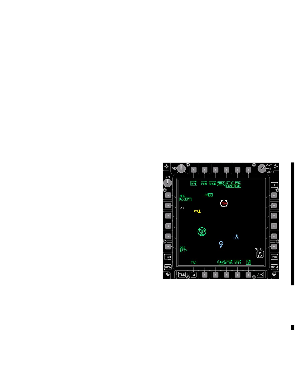
TM 1-1520-251-10
NOTE
NOTE
Selecting the SEND/FIRE button on the
The abort feature allows full control and pre-
ARTY page will transmit the ARTY message
vents potential lock - up in a mission when
over the Fire Support Net regardless of the
connectivity with another platform is lost.
radio to which the crewmember is RTS’d.
k. FIRE Button. Selecting the FIRE button
transmits the on call request message. The FIRE button
i. ABORT Button. Selecting the ABORT button
will be displayed when the IDM is in operate mode, a radio
calls up the, CHECK ALL, SITREP, SPOT and ARTY
(FM1 or FM2) is assigned to the Fire Support net, a valid
MISSION buttons within the CLEAR grouped options.
primary subscriber is assigned, and all mission thread
requirements leading up to transmittal of the on call
(1) Clear Check Fire All (CHECK ALL) But-
request have been satisfied.
ton. Selection of the CLEAR CHECK ALL button
l. ENGAGE Status. The ENGAGE Status window
commands the system to delete check fire all information.
is presented on the ARTY page when all conditions have
Prior to abort, the mission data is used to drive
been fulfilled to indicate an ON CALL request message
presentation and selection capability for related buttons,
needs to be transmitted to request artillery fire.
status windows, and symbols. The check fire all consists
3A.100.13 Airfire
(AF) Page. The AF page (fig
of data retained from the check fire - all and cancel check
3A-132) provides the ability to send and receive air fire
fire - all messages.
mission messages using the IDM to primary tactical inter-
net or fire support net members.
(2) Clear Situation Report
(SITREP) But-
ton. Selection of the sitrep button commands the
system to delete all received situation report information,
including the sitrep icon and sitrep status window.
(3) Clear Spot Report (SPOT) Button. Selec-
tion of the spot button commands the system to delete all
received spot report information, including the spot icon
and spot status window.
(4) Clear ARTY MISSION Button. Selection of
the CLEAR MISSION button commands the system to
delete all CFF mission related information. Prior to abort,
the mission data is used to drive presentation and
selection capability for related buttons, status windows,
and symbols. The call for fire mission consists of data
retained from the, call for fire, message to observer,
observer mission update, on call request, check
fire - target, cancel check fire - target, subsequent adjust
(REPEAT and ADJUST) and end of mission and
surveillance messages.
LBA5039C
NOTE
Figure 3A-132. Airfire (AF) Page
The AF page contains the following unique buttons:
Only the primary FS Net member can be ad-
dressed for a transmit message.
• T5
Subscriber button
• L1
MSG button
j. SEND Button. Selecting the SEND button
• L2
ABORT button
transmits the designated artillery message. The SEND
• L5
OBS SFTY button
button will be displayed when the IDM is in operate mode,
• R6
SEND button
a radio (FM1 or FM2) is assigned to the Fire Support net
radio, a valid primary subscriber is assigned, and all
3A.100.14 MSG Button. Selecting the MSG button
mission thread requirements leading up to transmittal of
enables configuration of the AF page for the airfire mes-
the designated JVMF message have been satisfied.
sage to be transmitted. Currently, all airfire messages
Use or disclosure of this information is subject to the restriction(s) on the title page of this document.
Change 4
3A-151
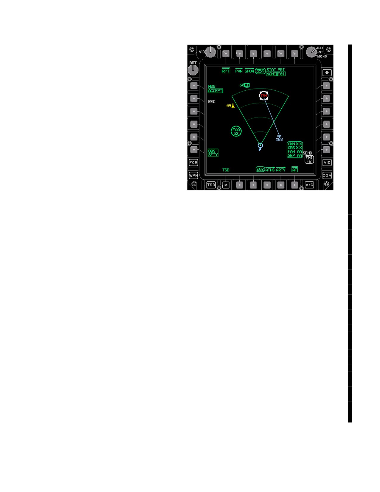
TM 1-1520-251-10
transmitted and received on the aircraft pertain to conduct
of a remote SAL Hellfire mission, in which the Apache acts
in the shooter (vs. observer) role. Normal sequence of
communications is as follows:
• Receive Remote SAL Hellfire mission request
• Transmit “Accept” or “Reject” (If transmit “reject”,
mission is considered terminated)
• Transmit “Ready”
• Receive “Fire”
• Transmit “Shot”
• Receive “End of Mission”
NOTE
Ensure Hellfire TOF caculation is available
prior to transmit of “READY”.
LBA5493
a. READY Button. Selecting the READY button
commands the system to transmit the “Ready” message,
Figure 3A-132A. AF Page OBS SFTY Selected
as well as pre - calculated time of flight, for the SAL remote
3A.100.15A OBS SFTY Button. Selecting the OBS
Hellfire mission when the crew member selects the SEND
SFTY button provides the operator with the information
button.
required to safely and effectively conduct an AF MIS-
SION. Refer to 3A-132A in support of the following:
b. SHOT Button. Selecting the SHOT button com-
a. SAL Missile Safety Fan. The SAL missile safety fan
mands the system to transmit the “Shot”message for the
is a green +/- 30 range fan extending from the ownhip loca-
SAL remote Hellfire mission when the crew member se-
tion with a range arc displayed every 2km to a max range dis-
lects the SEND button.
play of 8km and a range tic is dsiplayed at the 3, 5, and 7 km
increments. The safety fan is always available for display fol-
c. ACCEPT Button. Selecting the ACCEPT button
lowing primary EGI alignment.
commands the system to transmit the “Accept” message
b. OBS LOS cue. The OBS LOS cue is a blue line that
for the SAL remote Hellfire mission when the crew mem-
drawn between the AF target symbol modifier and the OBS
ber selects the SEND button.
symbol. The primary purpose for the cue is to provide a cue
to the OBServers location when not displayed on the MPD.
d. REJECT Button. Selecting the REJECT button
An AF mission message has to have been received prior to
commands the system to transmit the “Reject” message
the display of this cue.
for the SAL remote Hellfire mission when the crew mem-
c. AF CONTROL STATUS. The AF CONTROL STA-
ber selects the SEND button.
TUS status window is presented on the AF page when the a
OBS SFTY is selected and an AF mission message has
3A.100.15 ABORT Button. Selecting the ABORT but-
been received. The AF CONTROL STATUS status window
ton calls up the AF MISSION button.
displays: 1) OWN range; 2) OBS range; FAN GO/NG; and
SEP GO/NG. If the status values are all displayed in green
the mission may be executed safely without if a value is dis-
a. AF MISSION Button. Selection of the (clear)
played in white a performance paramter has been exceeded.
mission button commands the system to delete all airfire
The OBS range values are currently based off the OH-58D’s
mission related information. Prior to abort, the mission
laser performance for a 90% probablilty of a hit with a SAL
data is used to drive presentation and selection capability
missile.
for related buttons, status windows, and symbols. The air-
fire mission consists of data retained from all transmitted
3A.100.16 Subscriber Buttons. Are used to select
and received air fire mission messages relating to a re-
intended message recipients. Default is no subscribers se-
mote SAL Hellfire mission.
lected for any variation of the airfire mission message.
Use or disclosure of this information is subject to the restriction(s) on the title page of this document.
3A-152
Change 4
TM 1-1520-251-10
3A.100.17 ENGAGE Status. The ENGAGE status win-
a. POSITION button - Select.
dow is presented on the AF page when a SHOT message
(1) Enter new position in either UTM or
has been transmitted and an END OF MISSION message
LAT/LONG coordinates or enter an ex-
has not yet been received.
isting point number using the KU.
3A.100.18 END OF MSN Status. The END OF MSN sta-
(2) Fly over the known position, if not cur-
tus window is presented on the AF page, and indicates that
rently at that location.
an end of mission JVMF message has been received from
the airfire mission observer. This signifies the airfire mission
3 UPT button - Select.
as complete.
or
3A.101 INITIALIZATION
Option 3: TADS LOS
The Navigation subsystem initializes automatically upon
aircraft power application. The present position will be au-
a. POSITION button - Select. Enter new posi-
tomatically loaded by the SP. If a present position does not
tion in either UTM or LAT/LONG coordi-
exist, the crew can enter in the present position using the
nates or enter an existing point number us-
position update procedure (para 3A.101.1). Should power
ing the KU.
be interrupted, the system stores the last known aircraft
position. Upon application of power, the system initiates
b. RHG LRFD trigger - Press.
an alignment as follows:
c. LHG STORE/UPDT switch - UPDT.
• Starts EGI alignment
• Reads the last stored present position
3A.102 NORMAL OPERATIONS
• Sets the Doppler Radar to ON
• Sets the map viewing range to 25 km (upon ground
The following paragraphs describe procedural steps re-
power up)
quired for interface with the navigation subsystem via the
TSD, and the systems response to crewmembers input.
• Reads all stored routes from memory
• Reads all waypoint, hazard, control measure,
3A.102.1 Add a Waypoint, Hazard, Control Measure,
target, threat, line and area data
or Target/Threat.
• Sets the map and ownship symbol to the de-cen-
1. TSD page - Select.
tered position
• Sets TSD Map Frozen Cue
2. POINT page - Select.
• Reset Digital Map information
3. ADD button - Select.
3A.101.1 Perform a Fly-over or TADS LOS Position
4. TYPE button - Select Waypoint (WP), Hazard
Update.
(HZ), Control Measure (CM), or Target Threat
(TG).
1. TSD page - Select.
5. Option 1: Default Points Select a location on the
2. PSN button - Select.
map with the cursor.
3. Option 1: Cursor
or
a. Select a location on the map with the cursor.
(The accuracy of the cursor location in-
6. Option 2: Specific Points
creases with smaller map viewing ranges).
a. IDENT button - Enter Point identification on
b. Fly over the selected location, if not current-
KU or accept default.
ly at that location.
b. FREE Text - Select and/or, Enter.
c. UPT button - Select.
c. UTM LAT/LONG coordinates - Enter coor-
or
dinates on KU or accept default.
Option 2: Keyboard Entry
d. ALTITUDE - Select and/or, Enter.
Use or disclosure of this information is subject to the restriction(s) on the title page of this document.
Change 4
3A-153
TM 1-1520-251-10
3A.102.2 Store a Waypoint or Threat/Flyover.
3A.102.4 Create Priority Fire Zones.
1. TSD page - Select.
1.
TSD page - Select.
2.
BAM page - Select.
2. POINT page - Select.
3. STO button - Select.
3.
TYPE - Set to PF.
4. TYPE button - Toggle for Waypoint or Target/
4.
OPT button - Set to:
Threat.
a.
Select AUTO Button for AUTO method of
Priority Fire Zone creation.
5. Option 1: Fly-over.
(1) Set the #Z button.
a. Fly to the waypoint target/threat location.
(2) Accept default Draw (DR) Box (BX)
b. NOW button - Select.
method or select DR Line (LN) button.
or
(3) Select the corners of the Priority Fire
Zone using the cursor and enter func-
tion.
6. Option 2: TADS/HMD LOS Method.
(4) ASN button - Select.
a. Sight Select (CPG) - TADS or HMD.
(5) Select the desired PRI member but-
b. Place selected sight on waypoint or target/
ton(s) to assign the number of zones se-
threat.
lected above.
(6) XMIT BOTH button - Select (boxed) to
c. Provide desired Range source:
XMIT both the PF and NF as desired.
(1) TADS: Laser, Auto, Manual, or Default.
(7) IDM RTS - Confirm desired Longbow
protocol radio selected.
(2) HMD: Auto, Manual, or Default.
(8) SEND button - Select.
d. LHG Store button - Press.
b.
Select MAN method of PF creation.
3A.102.3 Add an Existing Point to the Current Route.
(1) Accept or modify the #Z button.
1. TSD page - Select.
(2) Accept default Draw (DR) Box (BX)
method or select DR Line (LN) button.
2. RTE page - Select.
3. ADD button - Select.
(3) Draw one to eight priority fire zones us-
ing the cursor and enter function in the
a. Cursor Method:
box or line mode. The number of zones
(1) Select existing point using cursor.
to draw is based on the #Z button.
(2) Select the point in the route grouped op-
(4) ASN button - Select
tions which the added point is inserted
(5) Select the desired PRI member but-
in front of.
ton(s) to assign that PF.
or
(6) XMIT BOTH button - Select (boxed) to
b. KU Method:
XMIT both the PF and NF as desired.
(1) POINT button select type, (W.H.C.), and
(7) IDM RTS - Confirm desired Longbow
number.
protocol radio selected.
(2) Select the point in the route grouped op-
(8) SEND button - Select.
tions which the added point is inserted
in front of.
or
Use or disclosure of this information is subject to the restriction(s) on the title page of this document.
3A-154
Change 3
TM 1-1520-251-10
c. Select TRP method of PF creation.
(2) PRI MEMBER button(s) - Select as ap-
propriate.
(1) KM button - Accept or modify.
(3) SEND button - Select.
(2) Select desired point on the map display
or
using the cursor and enter function.
(3) ASN button - Select.
d. PP - Select.
(4) Select PRI member button(s) to assign
(1) IDM RTS - Confirm desired protocol (L,
that PF to the selected member.
I, or F) radio selected.
(5) XMIT BOTH button - Select (boxed) to
(2) PRI MEMBER button(s) - Select as ap-
XMIT both the PF and NF as desired.
propriate.
(6) IDM RTS - Confirm desired Longbow
(3) SEND button - Select.
protocol radio selected.
3A.102.6 Request BDA, FARM, or PP Reports.
(7) SEND button - Select.
BDA and FARM reports are exclusively used with the
3A.102.5 Transmit BDA Reports (ALL or OWN), FCR
Longbow protocol while PP reports are used with Long-
TGT (Selective, ALL, PRI), FARM, or PP Reports.
bow, Tactical Internet, or Fire Support protocols.
BDA, FCR TGT, and FARM reports are exclusively used
1. TSD page - Select.
with the Longbow, Tactical Internet, or Fire Support proto-
2. RPT page - Select.
cols.
a. BDA or PP - Select.
1.
TSD page - Select.
(1) MSG button - RQST.
2.
RPT page - Select.
(2) IDM RTS - Confirm desired Longbow
a.
BDA - Select.
protocol radio selected.
(1) ALL or OWN - Select
(3) PRI MEMBER button(s) - Select as ap-
propriate.
(2) IDM RTS - Confirm desired Longbow
(4) SEND button - Select.
protocol radio selected.
3A.102.7 Add a NF Zone.
(3) PRI MEMBER button(s) - Select as ap-
propriate.
1. TSD page - Select.
(4) SEND button - Select.
2. BAM page - Select.
or
3. TYPE button - Select NF.
b.
TGT - Select.
4. SEL button - Select.
5. Select a NF (NF1 - NF8, as appropriate)
(1) Select ALL, PRI, or use cursor.
6. DR button - Select LN or BX.
(2) IDM RTS - Confirm desired Longbow
protocol radio selected.
a. Select four corners of a quadrilateral poly-
gon (or two corners of the box rectangle) us-
(3) PRI MEMBER button(s) - Select as ap-
ing the cursor.
propriate.
(4) SEND button - Select.
7. ACT (Active) or ACCEPT - Select.
or
8. IDM RTS - Confirm desired radio selected.
c.
FARM - Select.
9. PRI MEMBER button(s) - Select as appropriate.
(1) IDM RTS - Confirm desired Longbow
protocol radio selected.
10. SEND - Select.
Use or disclosure of this information is subject to the restriction(s) on the title page of this document.
Change 3
3A-155
TM 1-1520-251-10
3A.102.8 Transmit Situation (SIT) Report.
3A.102.10 Transmit/Receive Artillery Call For Fire
Mission Messages.
The following requires configuration of FM1 or FM2 to
support Tactical Internet or Fire Support digital commu-
The following artillery messages, listed in nominal se-
nications.
quential order, requires a tuned Fire Support protocol pre-
1. TSD page - Select.
set - net configuration using either the FM1 or FM2 radio.
2. RPT page - Select.
a. Transmit Observer Readiness Report (ORR).
3. SIT button - Select.
1. TSD page - Select.
4. MISSION button - Select as appropriate.
2. RPT page - Select.
5. OP NATURE button - Select as appropriate.
3. ARTY page - Select.
6. IDM RTS - Confirm desired radio selected.
4. MSG button - Select.
7. PRI MEMBER button(s) - Select as appropriate.
5. OBS RDY button - Select.
8. SEND button - Select.
6. PRI member button - Verify/set (FSE) as re-
quired.
3A.102.9 Transmit Spot Report (Priority FCR Targets
or Single Target).
7. SEND STATUS display - Confirm required FS
preset - net is tuned.
The following requires configuration of FM1 or FM2 to
support Tactical Internet or Fire Support digital
8. SEND button - Select.
communications.
1. TSD page - Select.
b. Transmit Call For Fire (CFF) - Ready or Can’t
Observe.
2. RPT page - Select.
The following steps represents a continuous mission
3. SPOT button - Select.
where the PLT or CPG has a TSD - RPT - ARTY page dis-
4. REPORT button - Verify or set TGT/THRT or
played following the transmittal of an ORR.
PRI/FCR as required.
1. MSG button - Select.
5. Target Source - Cursor select T## or FCR target.
2. CFF button - Select.
NOTE
Target information may be entered via L1
3. Target Source - Acquire using cursor select T##
target, FCR target, or use NTS FCR target.
sequential data entry button.
4. Target modifier symbol - Check that symbol is
6. THRT button - Select and enter sequential KU
centered around the correct target.
data as required (TGT/THRT, QTY, CRS, and
SPEED).
5. TARGET button - Verify/set as required.
7. ALLIANCE button - Select as appropriate.
6. QTY button - Verify or enter target quantity.
8. TARGET button - Verify/set as required.
7. CONTROL button - Verify/set as required.
9. ENEMY ACTIVITY button - Verify/set as re-
quired.
8. DANGER CLOSE button - Verify select/dese-
lect as required.
10. PRI MEMBER button(s) - Select as appropriate.
9. PRI member button - Verify/set (FSE) as re-
11. IDM RTS - Confirm desired radio selected.
quired.
12. SEND button - Select.
10. SEND button - Select.
Use or disclosure of this information is subject to the restriction(s) on the title page of this document.
3A-156
Change 3
TM 1-1520-251-10
c. Receive Message to Observer (MTO).
e. Transmit On Call Request (AT MY CMD Con-
trol).
When the IDM receives a MTO message, an advisory
To transmit an On Call Request Message, a CFF with a
tone will sound, the EUFD will display MSG TO OBSERV-
method of control of AT MY CMD has to have been pre-
ER, and the selection on the TSD REC button will display
viously transmitted, an approved MTO has to have been
a MSG TO OBSERVER message button.
received, MSG button must be selected to CFF and an
OMU update must indicate READY. The initiating PLT or
1. REC button - Select.
CPG receives feedback that the requirements for the On
Call Request have been met when receipt of the OMU
2. MSG TO OBSERVER button - Select.
causes display of a white ENGAGE! status window and
3. MTO symbol modifier - Cursor select and re-
the FIRE button appears in place of the SEND button.
view data contents of MESSAGE TO OBSERV-
ER display window.
1. MTO - Receive.
NOTE
2. MSG button selected to CFF.
The TSD-RPT-ARTY page STAT button
may also be used to maximize and minimize
3. ENGAGE! status window - Displayed.
the MTO message display window.
4. FIRE button - Select to send FIRE command at
the optimum time/situation.
d. Receive Observer Mission Update (OMU).
f. Transmit End of Mission (EOM) and/or Surveil-
When the IDM receives an OMU message, an advisory
lance (SURV).
tone will sound, the EUFD will display OBS MSN UP-
DATE, and the selection of the TSD REC button will dis-
1. MSG button - Select.
play an OBSERVER MSN UPDATE message button.
During the process of a typical artillery mission the FSE
2. EOM or EOM/SURV button - Select as required.
may transmit up to 6 OMU messages. Once received, a
secondary OMU status window is available and its display
3. SEND button - Select.
is controlled using the MTO status display. Depending on
the method of control and the message thread, the OMU
g. Abort Call For Fire Mission (ARTY MISSION).
status window will display UPDATE with READY, SHOT,
SPLASH, or ROUNDS COMPLETE and TOF: XXX SEC.
The ARTY MISSION abort feature is used to clear an artillery
mission upon its completion or to clear an incomplete mission
1. REC button - Select.
(in the middle of its message threads) if connectivity was lost
with the FSE prior to mission completion. The abort function
2. OBSERVER MSN UPDT button - Select.
is designed to only clear the artillery mission threads inclusive
of all artillery symbol modifiers and status windows. The abort
3. MTO symbol modifier - Cursor select, as required,
function does not inform the FSE that the mission has been
and verify OBSERVER MSN UPDATE data.
terminated.
NOTE
1. TSD page - Select.
• TOF countdown begins at the time the
2. RPT page - Select.
OMU message, indicating READY, is physi-
cally received by the PLT or CPG, while the
3. ARTY page - Select.
OMU message was transmitted at the actu-
al time of artillery fire.
4. MSG button - Select.
• The OMU display window will always dis-
play maximized whenever TOF is equal
5. ABORT button - Select.
to or less than 30 seconds and has not
yet counted down to zero.
6. ARTY MISSION button - Select.
Use or disclosure of this information is subject to the restriction(s) on the title page of this document.
Change 2
3A-157
TM 1-1520-251-10
h. Transmit Check Fire - Target or All.
i. Transmit Cancel Check Fire (EOM and RE-
SUME) Message.
An MTO has to be received into the crew station prior to
An operator acknowledgement request is always sent to
the platform enabling the control that permits transmitting
AFATDS as part of the CANC CHK message. An AFATDS
a CHK FIRE TARGET SINGLE message.
OPERATOR ACK sent to the originator of a CANC CHK
type message provides feedback that the FDC:
1) Ac-
The CHK FIRE TARGET ALL message option is always
knowledged (ACK); 2) Will Comply (WILCO); 3) Can’t
accessible in support of a contingency requirement to
Comply (CANTCO); or 4) Have Complied (HAVCO)
shutdown all artillery fires on a battlefield sector. An oper-
ator acknowledgement request is always sent to AFATDS
1. MSG button - Select.
as part of both the CHK FIRE TARGET SINGLE and CHK
2. CANC CHK button - Select.
FIRE TARGET ALL messages. An AFATDS OPERATOR
NOTE
ACK sent to the originator of a Check Fire message pro-
vides feedback that the FDC: 1) Operator Acknowledged
There are two options used for canceling
(ACK); 2) Will Comply (WILCO); 3) Can’t Comply
check fires: 1) EOM = cancel the mission
(CANTCO); or 4) Have Complied (HAVCO).
without resuming fires; 2) CANC CHK = re-
sume fires and cancel the check fire condi-
1. TSD page - Select.
tion
3. End of Mission Option
2. RPT page - Select.
a. EOM Button - Select.
3. ARTY page - Select.
b. SEND button - Select.
4. MSG button - Select.
Sending an EOM Button will end both the
5. CHK FIRE button - Select.
active artillery mission and end the active
CHK FIRE status (single or all).
6. TARGET button - Verify/select SINGLE or ALL.
c. CANC CHK - Observe automatic send via
NOTE
the STAT LAST following the EOM send
commande
TARGET ALL. is barriered until a MTO has
4. Resume Fire Option
been received and TARGET SINGLE is the
default selection following the receipt of a
a. CANC CHK Button - Select.
MTO.
When CANC CHK is selected and the mes-
sage is subsequently sent, the artillery is
7. PRI member button - Verify/set (FSE) as re-
then cleared to resume firing: a CANC CHK
quired.
is only performed when it is desired to re-
8. SEND button - Select.
sume fires and end the active check fire
condition.
NOTE
b. EOM Button - Select.
To ensure that the CALL FOR FIRE STAT
NOTE
window is not prematurely overwritten, the
To ensure that the CALL FOR FIRE STAT
aircrew should not transmit any other JVMF
window is not prematurely overwritten, do
messages following the transmission of a
not transmit any other JVMF messages fol-
CHK FIRE message (when possible) until
lowing the transmission of a EOM/CANC
the AFATDS operator sends an operator re-
CHK message until the AFATDS operator
sponse
sends an operator response
9. ACK STAT window (auto displayed) - Observe
5. ACK STAT window (auto displayed) - Observe
AFATDS operator ACK response for any of the
AFATDS operator ACK response for any of the
following: 1) Acknowledged (ACK); 2) Will
following: 1) Acknowledged (ACK); 2) Will
Comply (WILCO); 3) Can’t Comply (CANTCO);
Comply (WILCO); 3) Can’t Comply (CANTCO);
or 4) Have Complied (HAVCO)
or 4) Have Complied (HAVCO)
Use or disclosure of this information is subject to the restriction(s) on the title page of this document.
3A-158
Change 4
TM 1-1520-251-10
j. Abort Check Fire Mission (ARTY MISSION).
7. PRI member button - Verify/set (FSE) as re-
quired,
The abort CHECK ALL function is designed to only clear
the CHECK ALL threads and the CHECK ALL symbol
8. SEND button - Select.
modifiers and status windows.
1. TSD page - Select.
3A.102.11 Receive Tactical Messages (General).
2. RPT page - Select.
Messages that may be received from the TSD page REC
3. ARTY page - Select.
are listed in paragraph 3A.79.15. The following requires
4. MSG button - Select.
configuration of the radio to support AFAPD, Tactical In-
ternet, or Fire Support net digital communications as ap-
5. ABORT button - Select.
propriate.
6. CHECK ALL button - Select.
1. TSD page - Select.
k. Transmit Subsequent Adjust - Repeat.
2. REC button - Select.
The repeat message capability is enabled in the ownship
following the receipt of a MTO during an active call for fire
3. REC option button - Select as appropriate.
mission from the CPG station. This message is used to in-
dicate error in artillery targeting by relaying location of
4. TI and FS Messages - Open and review data as
rounds impact.
required.
1. MSG button - Select.
2. REPEAT button - Select.
3A.102.12 Receive/Transmit Air Fire Messages (SAL
Shooter Role).
3. CONTROL button - Verify/set as required.
4. DANGER CLOSE button - Verify or select/de-
select as required.
The following requires configuration of FM1 or FM2 to ei-
ther Fire Support or Tactical Internet digital
5. PRI member button - Verify/set (FSE) as re-
communications.
quired.
6. SEND button - Select.
a. Receive Air Fire Mission (AFM) SAL Shooter
l. Transmit Subsequent Adjust - Rounds Impact.
Request.
The rounds impact (repeat) message capability is enabled
1. AIRBORNE FIRE MISSION - EUFD message
in the ownship following the receipt of a MTO during an
advisory displayed.
active call for fire mission from the CPG station. This mes-
sage is used to indicate error in artillery targeting by relay-
2. TSD page - Select.
ing location of rounds impact.
3. RPT page - Select.
1. MSG button - Select.
2. ADJUST button - Select.
4. AF page - Select.
3. CONTROL button - Verify/set as required.
5. REC button - Select.
4. STORE button - Verify or select/deselect as re-
quired.
6. MSG button - Select as appropriate.
5. TADS/HMD - Acquire and range (Laser, MAN,
7. AIR FIRE MISSION message button - Select.
AUTO, default) rounds impact.
6. STORE button - Select LHG STORE button or
8. AFM symbol modifier - Cursor select and re-
TSD POINT page STORE button.
view data contents of display window.
Use or disclosure of this information is subject to the restriction(s) on the title page of this document.
Change 4
3A-159
TM 1-1520-251-10
NOTE
2. AIR FIRE MISSION message button - Select.
The TSD-RPT-AFM page STAT button
e. Transmit - SHOT.
may also be used to maximize and minimize
the MTO message window.
Once the SHOT message is transmitted the ENGAGE!
status window is displayed in white to denote that the tar-
b. Transmit - ACCEPT/REJECT.
get should now be engaged.
Once an AFM is accepted, the remainder of the message
1. MSG button - Verify/select SHOT.
threads are conducted from the AF page. Accepting a
2. PRI member button - Verify/set as required.
mission does not mean that the aircraft is necessarily
ready. The AF page. OBS - SFTY button should be se-
3. IDM RTS - Confirm desired radio selected as
lected and the mission parameters should be evaluated to
required.
determine when and if the mission can be executed. If a
4. SEND button - Select.
mission is rejected, the mission thread is complete and
the mission will have to be aborted (cleared) by the opera-
f. Receive Air Fire Mission End of Mission (EOM)
tor prior to initiating a new mission.
Message.
1. OBS SFTY button - Select and evaluate safety
Once the EOM message is received, the END OF MISSION
parameters
status window is displayed in white on the AFM page.
2. RPT page - Select as required.
1. REC button - Select.
3. AF page - Select as required.
2. AIR FIRE MISSION message button - Select.
4. MSG button - Verify default or select as re-
quired.
3A.102.13 Abort AF Mission Thread.
5. ACCEPT or REJECT button - Select as re-
1. TSD page - Select.
quired.
2. RPT page - Select.
6. PRI member button - Verify/set as required.
3. AF page - Select.
7. IDM RTS - Confirm desired radio selected as
4. MSG button - Select.
required.
5. ABORT button - Select.
8. SEND button - Select.
6. AF MISSION option button - Select to delete
c. Transmit - Ready.
mission data.
Once the aircraft is within constraints and ready to fire, the
3A.102.14 Abort RPT and ARTY Mission Threads.
READY message is transmitted.
1. TSD page - Select.
1. MSG button - Verify/select READY.
2. RPT page - Select.
2. PRI member button - Verify/set as required.
3. ARTY page - Select.
3. IDM RTS - Confirm desired radio selected as
required.
4. MSG button - Select.
4. SEND button - Select.
5. ABORT button - Select.
d. Receive - FIRE Command.
6. CHECK ALL, SITREP, SPOT or ARTY MIS-
1. REC button - Select.
SION option button - Select as appropriate.
Use or disclosure of this information is subject to the restriction(s) on the title page of this document.
3A-160
Change 4
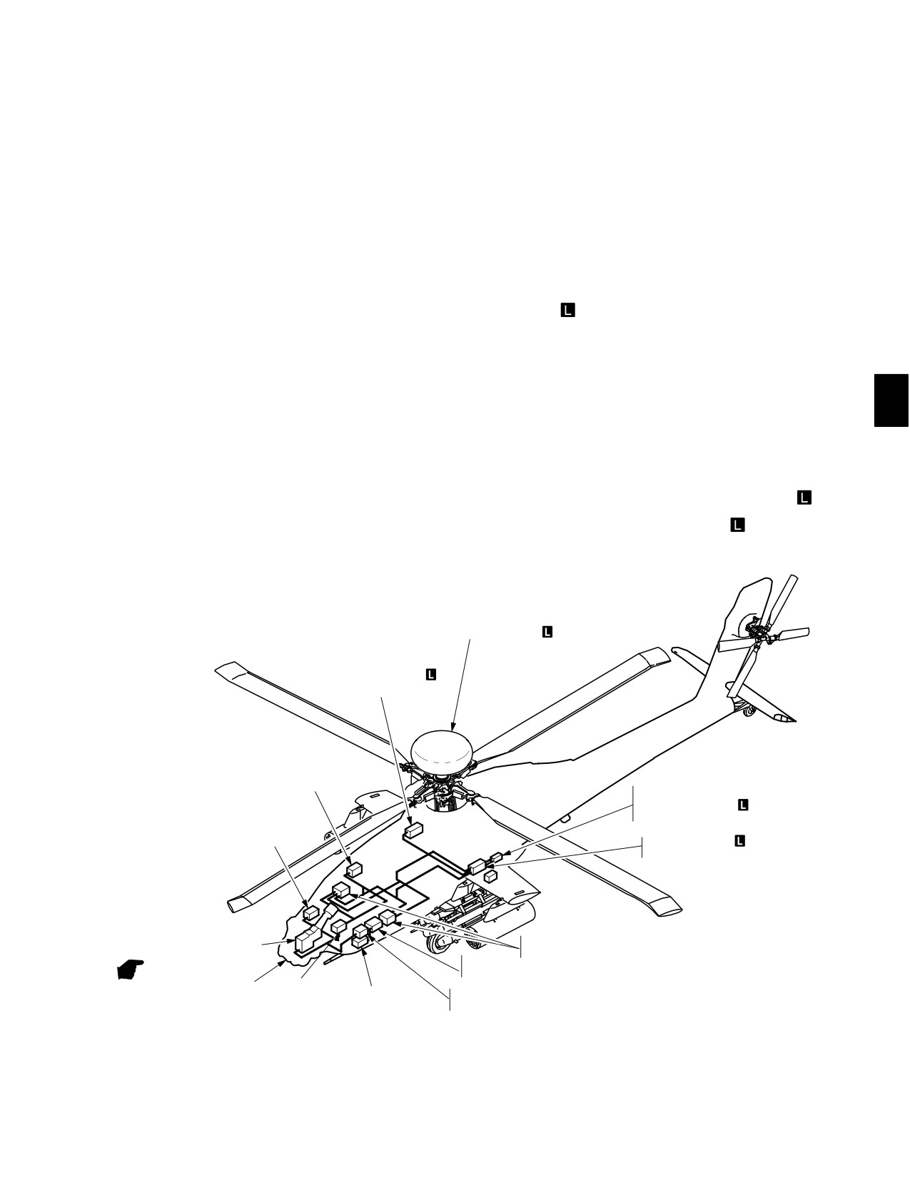
TM 1-1520-251-10
CHAPTER 4
MISSION EQUIPMENT
Section I. SIGHTING SUBSYSTEM
4.1 INTRODUCTION
The sighting system (fig 4-1) uses Electro-Optical (EO)
and radar
components to provide target acquisition/
designation and navigation assistance capabilities in day,
night, and limited visibility conditions. The system pro-
This section provides a description of the helicopter Sight
vides the means to aim Hellfire missiles, the gun, or rock-
Subsystem and associated operational procedures. It in-
ets. The sighting system consists of the following:
cludes a description of sight components, controls and
displays, system operations, and procedural checklists.
• Integrated Helmet and Display Sight System
(IHADSS)
•
AN/AAQ - 11 Pilot Night Vision Sensor (PNVS)
• AN/ASQ - 170 Target Acquisition Designation
Due to the integration of functionality throughout compo-
Sight (TADS)
nents of the Mission Equipment, some descriptions and
• AN/APG - 78 Fire Control Radar (FCR)
operational procedures are covered under more than one
heading. To understand the complete operation of these
IHADSS, TADS, PNVS, and the FCR
can operate inde-
systems, it is necessary to understand this complete
pendently or in various sensor combinations as acquisi-
chapter as well as related data in chapter 3.
tion and range sources.
MAST MOUNTED ASSEMBLY
LOW−POWER RADIO
FREQUENCY
SIGHT
ELECTRONICS
UNIT
RADAR FREQUENCY
INTERFEROMETER
PNVS
PROCESSOR
ELECTRONICS
UNIT
PROGRAMMABLE
SIGNAL PROCESSOR
OPTICAL RELAY TUBE/
WEAPONS
TADS ELECTRONIC DISPLAY
TADS
PROCESSORS
AND CONTROL
ELECTRONICS UNIT
DISPLAY
TADS/PNVS
LASER
TADS
ELECTRONICS
TURRETS
ELECTRONICS UNIT
POWER SUPPLY
UNIT
LBA2016A
Figure 4-1. Sight Subsystem
Use or disclosure of this information is subject to the restriction(s) on the title page of this document.
Change 4
4-1
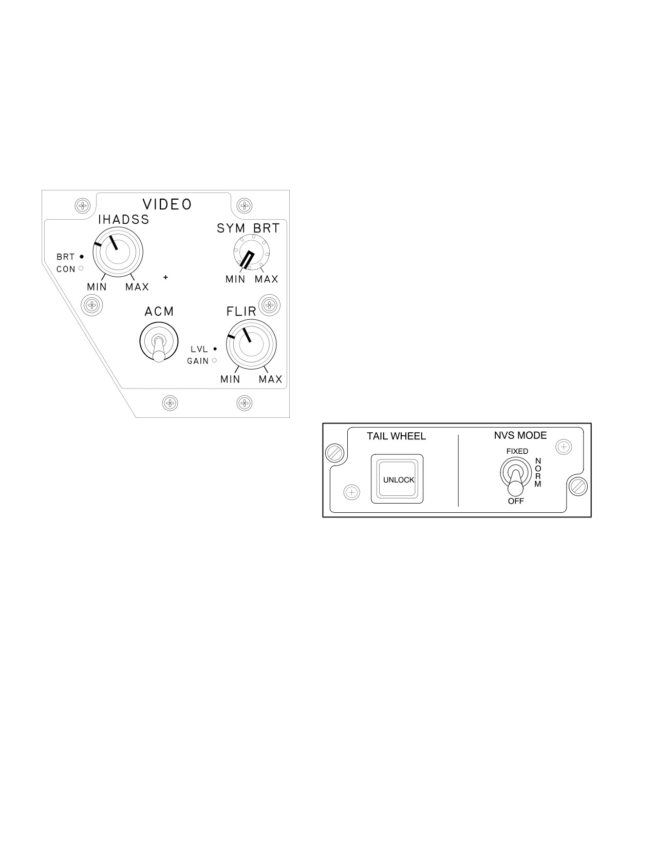
TM 1-1520-251-10
4.2 VIDEO CONTROL PANEL
4.2.5 FLIR Level. The FLIR LVL control adjusts FLIR
level for the PNVS or TADS FLIR imagery as selected at
the (NVS) select switch.
The pilot VIDEO control panel (fig 4-2), located on the left
side of the pilot instrument panel, allows the crewmember
4.2.6
Automatic Contrast Mode (ACM). The ACM
to adjust the brightness and contrast intensity of the HMD,
control provides automatic FLIR gain and level control.
symbology brightness, and gain and level of the FLIR vid-
The ACM position disables the FLIR gain and level con-
eo.
trols and automatically adjusts FLIR gain and level control
to compensate for scene thermal content changes and
switching polarities. The down position (no label) disables
ACM and enables the FLIR GAIN and FLIR LVL knobs.
ÑÑ
4.3 NVS MODE PANEL
ÑÑÑÑ
ÑÑÑ
ÑÑ Ñ
ÑÑÑ
The NVS Mode Panel (fig 4-3), located on the left console
ÑÑÑÑ
ÑÑ
in each crew station, contains the NVS MODE switch. The
NVS MODE switch selects the operational mode of the
selected NVS. The OFF position commands the selected
NVS to the stow position. The NORM (center) position
ÑÑÑ
commands the selected NVS to slew to the crewmembers
IHADSS Line Of Sight (LOS). The FIXED position com-
ÑÑÑÑ
mands the selected NVS to the fixed forward position. The
ÑÑÑÑ
Pilot’s default NVS sensor is PNVS and the CPG’s default
ÑÑÑ
NVS sensor is TADS. This can be changed by selecting
the NVS SELECT switch on the collective and follows the
last select logic.
LBA0088
Figure 4-2. Pilot VIDEO Panel
4.2.1
Symbol Brightness. The SYM BRT control ad-
justs the intensity of the symbology brightness. The ad-
justment varies from black to white.
LBA1986
4.2.2 IHADSS Display Brightness. The IHADSS BRT
Figure 4-3. NVS MODE Panel
control adjusts the grayscale and/or image brightness in-
tensity.
4.4 CYCLIC CONTROL GRIP
4.2.3
IHADSS Display Contrast. The IHADSS CON
The cyclic control grip (fig 4-4) in each crewstation in-
control adjusts the grayscale and/or image contrast inten-
cludes a symbology select (SYM SEL) switch. The SYM
sity.
SEL switch selects 1 of 4 modes of IHADSS flight symbol-
ogy. The 2 aft selections are Hover (H) and Bob-up (B);
4.2.4 FLIR Gain. The FLIR GAIN control adjusts FLIR
the 2 forward selections are Transition (T) and Cruise (C).
gain for the PNVS or TADS FLIR imagery as selected at
Depressing the SYM SEL switch will also cause the FLT
the Night Vision System (NVS) select switch.
page to display on the left MPD.
Use or disclosure of this information is subject to the restriction(s) on the title page of this document.
4-2
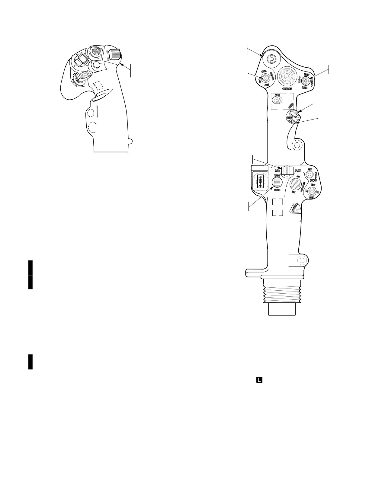
TM 1-1520-251-10
FCR SCAN
SIZE
Z
N
W
SYMBOLOGY
M
SIGHT
SELECT
SELECT
FCR MODE
SWITCH
FCR SCAN
CUED SEARCH
LBA1039
BORESIGHT/
POLARITY
Figure 4-4. Cyclic Control Grip
ÓÓ
ÓÓ
4.5 COLLECTIVE CONTROL
ÓÓ
The collective control (fig 4-5) in each crew station is
TADS/PNVS
equipped with a mission control grip and flight control grip
SELECT
and provides access to various sight subsystem controls.
4.5.1
Polarity/Boresight. The PLRT B/S switch is
used to store the IHADSS boresight alignment and
change FLIR image polarity.
If the aircraft is equipped with MTADS - MPNVS provi-
sions, the PLRT position of the PLRT B/S switch is used
to change FLIR image polarity. The B/S position is a
growth position for MPNVS sensor selection.
NOTE
If the pilot selects TADS, either with the NVS
LBA1035
select switch or linking the TADS to the
FCR, while the CPG is sight select TADS,
the CPG’s sight will default to HMD and
weapons will be de-actioned.
Figure 4-5. Collective Control Grip
4.5.2 NVS Select. The NVS Select switch is a two posi-
tion momentary switch (PNVS, TADS FLIR). The night vi-
sion sensor select switch is used in conjunction with the
NVS mode switch to select the desired night vision sen-
4.5.3
FCR Mode
The FCR mode switch selects 1 of
sor. To control a NVS, set the select switch to the desired
4 operational modes of the FCR. This function is active
NVS and set the NVS mode switch for desired operation
only when the FCR is the selected sight. Placing the
(para 4.3). Selection of an NVS by a crewmember will au-
switch momentarily to the desired position selects the re-
tomatically provide the remaining NVS to the other crew-
spective mode: ground targeting mode (GTM), radar map
member. NVS control is updated to the most recent selec-
mode (RMAP), air targeting mode (ATM), or terrain pro-
tion made.
files mode (TPM).
Use or disclosure of this information is subject to the restriction(s) on the title page of this document.
Change 4
4-3
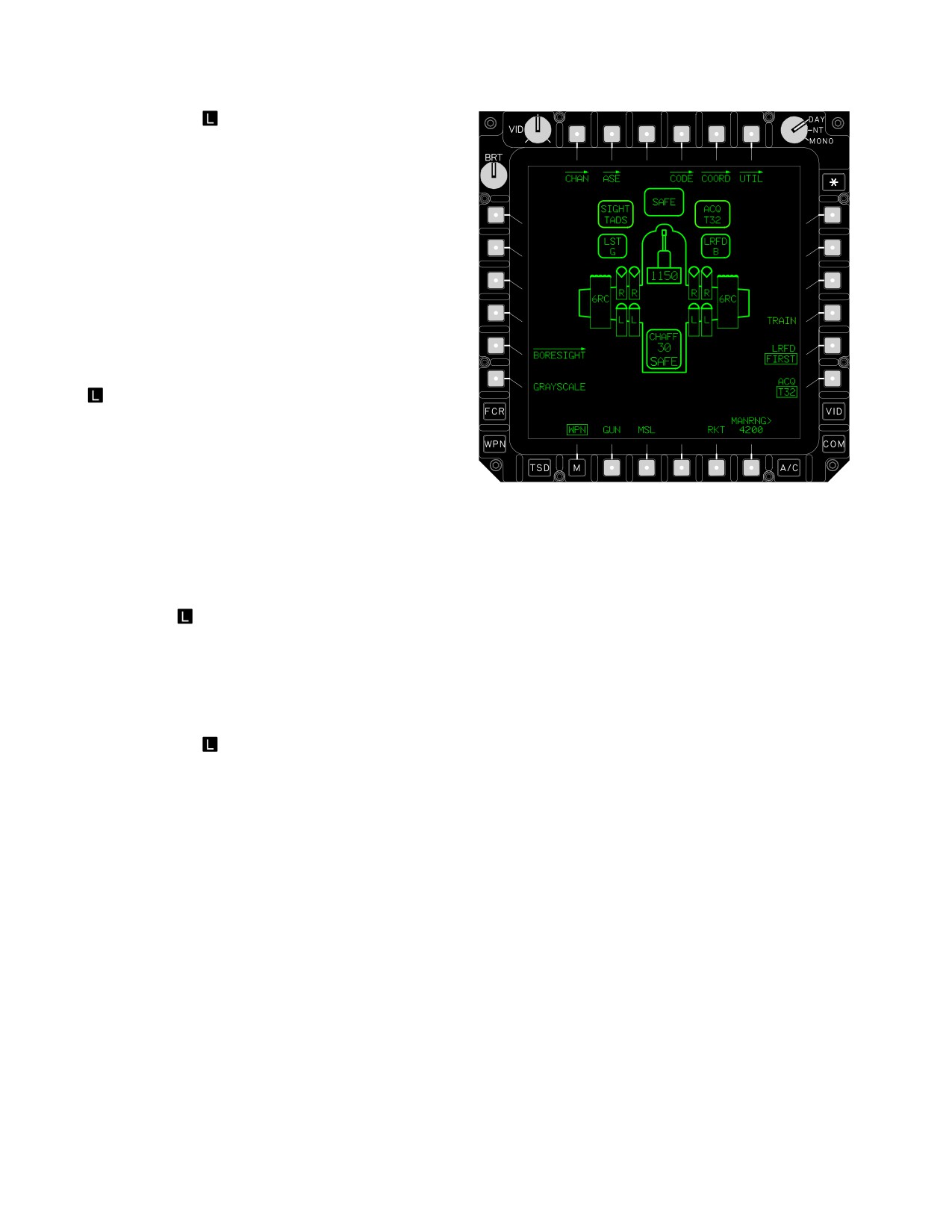
TM 1-1520-251-10
4.5.4 FCR Scan Size
The FCR scan size switch se-
lects one field of view (scan width) for the selected FCR
targeting mode. This function is active only when the FCR
is the selected sight. The scan size state remains as last
selected regardless of the targeting mode. Placing the
switch momentarily to the desired position selects the re-
spective scan size: wide, (W), medium, (M), narrow, (N),
or zoom (Z).
4.5.5 Sight Select. The sight select switch is used to
select one of three sights or to link the TADS and FCR.
This switch is independently controlled in each crewsta-
tion. Placing the switch momentarily to the desired posi-
tion selects the respective mode: HMD, TADS, FCR, or
LINK
. The LINK function sets the FCR centerline to the
TADS LOS when the selected sight is TADS, or sets the
TADS LOS to the FCR NTS LOS when the selected sight
is FCR. Reselecting the LINK function toggles LINK off.
The TADS sight select switch is not active in the pilots’
crewstation. FCR sight selection is based on the last to
LBA0564A
select logic. Selection of the FCR through the sight select
switch automatically displays the FCR targeting format for
Figure 4-6. WPN Page
the selected mode on the left MPD. Refer to paragraph
4.47.4 for LINK function description.
The WPN page contains the following unique sight but-
tons:
• T4
Laser CODE button
4.5.6 FCR SCAN
The FCR SCAN switch activates
and deactivates the FCR transmitter. This function is ac-
• T6
WPN UTIL button
tive when the FCR is the selected sight. The switch is also
• L5
BORESIGHT button
active in the CPG station when the TADS is the selected
• L6
GRAYSCALE button
sight and link function is selected.
•
R5
LRFD button
• R6
ACQ button
4.5.7
CUED Search
The CUED search switch is
• B6
MANRNG button
used to rapidly orient the FCR antenna toward an RFI de-
tected emitter and conduct an FCR scan to correlate the
4.6.1 Laser CODE Butto. The CODE button accesses
location of that emitter in the GTM, ATM, and RMAP tar-
stored laser codes.
geting modes. This function is active only when the FCR is
4.6.2
WPN UTIL Button. The WPN UTIL button ac-
the selected sight.
cesses sight subsystem utility functions.
4.6.3
BORESIGHT Button. The BORESIGHT button
4.6 WEAPONS (WPN) PAGE
accesses the IHADSS/TADS boresight controls.
4.6.4 GRAYSCALE Button. The GRAYSCALE button
The WPN page (fig 4-6) is used to functionally control
activates the grayscale mode for display on the crew
sight and weapons moding. Selecting the WPN Subsys-
members HMD.
tem button or the WPN page button from the MENU page
calls up the WPN page. Various sight and weapons sub-
4.6.5 LRFD Button. The LRFD button selects between
system status windows, icons, and control selections are
the FIRST or LAST in a series of laser range pulses for
included on the page to reduce workload and enhance sit-
processing as the laser range value.
uational awareness. Some status and control selections
are common to both crew stations while others are crew
4.6.6 ACQ Button. The ACQ button selects an acquisi-
station unique. Weapons subsystem descriptions are pro-
tion source to slave or cue the selected sight to another
vided in Section II.
line of sight or a point on the ground.
Use or disclosure of this information is subject to the restriction(s) on the title page of this document.
4-4