JEPPESEN GENERAL AIRWAY MANUAL (Issue Date 1 JUL 21) - page 31
 

  Index      Manuals     JEPPESEN GENERAL AIRWAY MANUAL (Issue Date 1 JUL 21)


Search            copyright infringement  


Content      ..     29      30      31      32     ..


JEPPESEN GENERAL AIRWAY MANUAL (Issue Date 1 JUL 21) - page 31


Figure II-1-1-3. Fly-over waypoint

INTERNATIONAL CIVIL AVIATION ORGANIZATION -

FLIGHT PROCEDURES

961

FLIGHT PROCEDURES - (DOC 8168) - GENERAL REQUIREMENTS

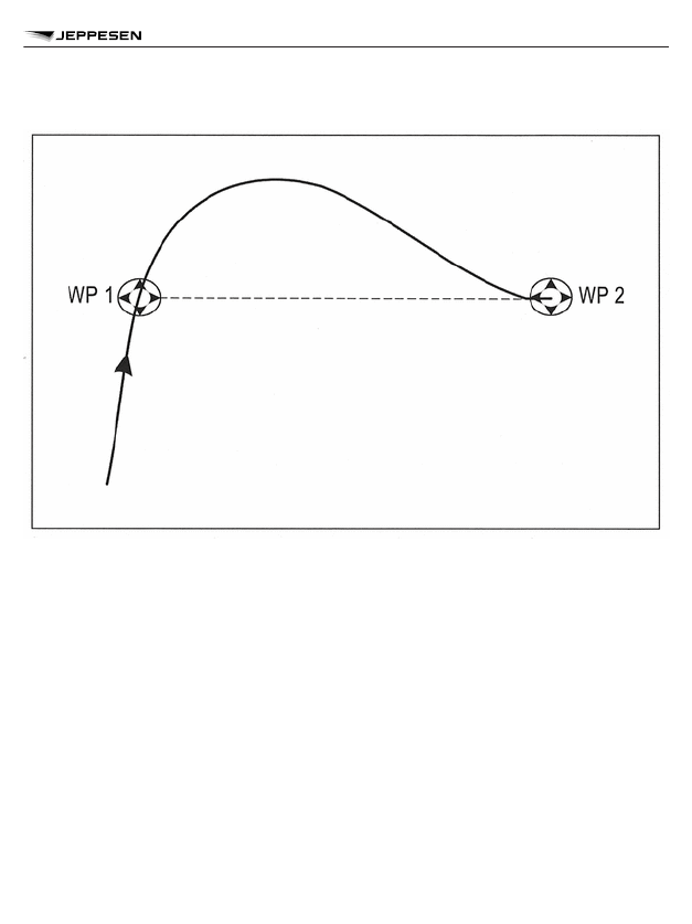
Figure II-1-1-4. RF turn

INTERNATIONAL CIVIL AVIATION ORGANIZATION -

FLIGHT PROCEDURES

962

FLIGHT PROCEDURES - (DOC 8168) - GENERAL REQUIREMENTS

Extracted from ICAO Document 8168, Volume I - Sixth Edition - Procedures for Air Naviga-
tion Services - AIRCRAFT OPERATIONS, Flight Procedures, herein known as PANS-OPS.

GENERAL REQUIREMENTS

INTRODUCTION

1.1.1  The criteria in this section are designed to provide the pilot and other flight operations per-
sonnel with an appreciation, from the operational point of view, of the parameters and criteria
used in the design of instrument departure procedures. These include, but are not limited to,
standard instrument departure (SID) routes and associated procedures (see Annex 11, Appendix
3).
1.1.2  These procedures assume that all engines are operating. In order to ensure acceptable
clearance above obstacles during the departure phase, instrument departure procedures may be
published as specific routes to be followed or as omnidirectional departures, together with proce-
dure design gradients and details of significant obstacles.
1.1.3  A departure procedure is established for each runway on which an instrument departure is
expected to be used. Procedures will be developed for different categories of aircraft as required.

CONTINGENCY PROCEDURES

1.2.1  Development of contingency procedures, required to cover the case of engine failure or an
emergency in flight which occurs after V1, is the responsibility of the operator, in accordance with
Annex 6. Where terrain and obstacles permit, these procedures should follow the normal depar-
ture route.

Turning procedures

When it is necessary to develop a turning procedure to avoid an obstacle which would have
become limiting, the procedure should be described in detail in the appropriate operator or aircraft
manual. The point for start of turn in this procedure shall be readily identifiable by the pilot when
flying under instrument conditions.

INSTRUMENT DEPARTURE PROCEDURE

Design considerations

The design of an instrument departure procedure is, in general, dictated by the terrain surround-
ing the aerodrome. It may also be required to provide for air traffic control (ATC) requirements in
the case of SID routes. These factors in turn influence the type and siting of navigation aids in
relation to the departure route. Airspace restrictions may also affect the routing and siting of navi-
gation aids.

Aerodrome operating minima

Where obstacles cannot be cleared by the appropriate margin when the aircraft is flown on instru-
ments, aerodrome operating minima are established to permit visual flight clear of obstacles.

1

1.1

1.2

1.2.2

1.3

1.3.1

1.3.2

INTERNATIONAL CIVIL AVIATION ORGANIZATION -

FLIGHT PROCEDURES

963

FLIGHT PROCEDURES - (DOC 8168) - DEPARTURE PROCEDURES

Wind effect

1.3.3.1  When flying departure routes expressed as tracks or bearings, the pilot shall compen-
sate for known or estimated winds.
1.3.3.2  When being vectored, the pilot should not compensate for wind effects.

Vectors

Pilots should not accept vectors during departure unless:

a. they are above the minimum altitude(s)/height(s) required to maintain obstacle clearance in

the event of engine failure. This relates to engine failure between V1 and minimum sector
altitude or the end of the contingency procedure as appropriate; or

b. the departure route is non-critical with respect to obstacle clearance.

OBSTACLE CLEARANCE

1.4.1  The minimum obstacle clearance (MOC) equals zero at the departure end of the runway
(DER). From that point, it increases by 0.8 per cent of the horizontal distance in the direction of
flight assuming a maximum turn of 15°.
1.4.2  During the turn, a MOC of 75 m (246 ft) (CAT H, 65 m (213 ft)) is provided.

PROCEDURE DESIGN GRADIENT (PDG)

1.5.1  Unless otherwise published, a PDG of 3.3 per cent is assumed.
1.5.2  For conversion of climb gradient for cockpit use, see Figure II-2-1-2.

FIXES AS AN AID IN OBSTACLE AVOIDANCE

Whenever suitably located distance measuring equipment (DME) exists, additional specific
height/distance information intended for obstacle avoidance may be published. Waypoints or
other suitable fixes should be used by the pilot to provide a means of monitoring climb perform-
ance.

PERFORMANCE-BASED NAVIGATION (PBN) DEPARTURES

1.7.1  Description. A PBN departure is a departure procedure containing area navigation (RNAV)
or required navigation performance (RNP) segments.
1.7.2  PBN requirements box. PBN departure procedures are promulgated with a PBN require-
ments box. The box contains the following information:

a. identification of the applicable navigation specification(s) that were used to design the depar-

ture procedure;

b. restrictions on navigation equipment required to fly the procedure (for example, global navi-

gation satellite system (GNSS) only) if applicable; and

c. information related to optional functionality of the applicable navigation specification such as

the use of constant radius arc to a fix (RF) legs or RNP scalability, if applicable.

1.3.3

1.3.4

1.4

1.5

1.6

1.7

INTERNATIONAL CIVIL AVIATION ORGANIZATION -

FLIGHT PROCEDURES

964

FLIGHT PROCEDURES - (DOC 8168) - DEPARTURE PROCEDURES

Applicable navigation specifications

The applicable navigation specifications for PBN departure operations are:

a. RNAV 2;
b. RNAV 1;

c. RNP 1;

d. RNP 0.3 (Helicopters); and
e. Advanced RNP (A-RNP).

NOTE: For complete details of the applicability of PBN navigation specifications to departure pro-
cedures, see the Performance-based Navigation (PBN) Manual (Doc 9613).
1.7.4  The navigation specifications may be applied on a departure route segment basis.
1.7.5  Navigation database. Departure procedure information is contained in a navigation data-
base using the WGS-84 coordinate system. If the navigation database does not contain the
departure procedure, the procedure shall not be used.

PBN operational approval

1.7.6.1  Pilots shall verify, before operating on any PBN route or procedure, that they have
approval to operate on the navigation specification used. Where there are additional restrictions,
for example, sensor use or optional functionality as discussed in para 1.7.2 above, the pilot shall
also verify that these restrictions are complied with.
1.7.6.2  Prior to operating on any PBN procedure, the pilot shall confirm:

a. the operation of all required navigation aids (ground and space-based);
b. the correct functioning of the navigation equipment;

c. the validity of the navigation database; and

d. waypoint and segment data, with reference to the published chart.

1.7.3

1.7.6

INTERNATIONAL CIVIL AVIATION ORGANIZATION -

FLIGHT PROCEDURES

965

FLIGHT PROCEDURES - (DOC 8168) - DEPARTURE PROCEDURES

Figure II-2-1-2. Conversion nomogram

INTERNATIONAL CIVIL AVIATION ORGANIZATION -

FLIGHT PROCEDURES

966

FLIGHT PROCEDURES - (DOC 8168) - DEPARTURE PROCEDURES

STANDARD INSTRUMENT DEPARTURES

GENERAL

2.1.1  A standard instrument departure (SID) is a departure procedure that is normally developed
to accommodate as many aircraft categories as possible. Departures that are limited to specific
aircraft categories are clearly annotated (see Section 5, Chapter 1, 1.4, “Categories of aircraft”).
2.1.2  For procedure design purposes, the SID terminates at the first fix/facility/waypoint of the
en-route phase following the departure procedure.
2.1.3  SIDs are based on track guidance acquired:

a. for conventional straight departures, within 20.0 km (10.8 NM) from the DER;
b. for conventional turning departures within 10.0 km (5.4 NM) after completion of turns; and

c. for PBN departure procedures normally at the DER.

PROCEDURE DESIGN GRADIENT

2.2.1  The standard design gradient for departure procedures is 3.3 per cent.
2.2.2  When obstacles exist which affect the departure route, procedure design gradients greater
than 3.3 per cent may be specified. When such a gradient is specified, the altitude/height to which
it extends is promulgated.
2.2.3  For information regarding rates of climb necessary to meet the specified climb gradients
the pilot should refer to Figure II-2-1-2.

STRAIGHT DEPARTURES

Wherever possible, a straight departure is specified. A straight departure is one in which the initial
departure track is within 15° of the alignment of the runway centre line.

TURNING DEPARTURES

2.4.1  When a departure route requires a turn of more than 15°, it is called a turning departure.
Straight flight is assumed until reaching an altitude/height of at least 120 m (394 ft). Procedures
normally cater for turns at a point 600 m from the beginning of the runway. However, in some
cases, turns should not be initiated before the DER (or a specified point), and this information will
be noted on the departure chart.
2.4.2  For Category H procedures, turns may be initiated 90 m (295 ft) above the elevation of the
DER or final approach and take-off area (FATO) and the earliest turn initiation point is at the
beginning of the runway FATO.
2.4.3  Flight speeds for turning departure are specified in Table II-2-2-1. Wherever limiting
speeds other than those specified in Table II-2-2-1 are promulgated, they shall be complied with
in order to remain within the appropriate areas. If an aeroplane operation requires a higher speed,
then an alternative departure procedure shall be requested.

2

2.1

2.2

2.3

2.4

INTERNATIONAL CIVIL AVIATION ORGANIZATION -

FLIGHT PROCEDURES

967

FLIGHT PROCEDURES - (DOC 8168) - DEPARTURE PROCEDURES

Turn speeds

2.4.4.1  The maximum speeds used for departure turns shall be those of the final missed
approach increased by 10 per cent to account for increased aeroplane mass in departure (see
Table II-2-2-1), unless otherwise annotated on the procedure.
2.4.4.2  In exceptional cases, where acceptable terrain clearances cannot otherwise be provi-
ded, turning departure routes are constructed with maximum speeds as low as the intermediate
missed approach speed increased by 10 per cent (see Tables II-5-1-1 and II-5-1-2). In such
cases, the procedure is annotated “Departure turn limited to ... km/h (kt) IAS maximum”.

Table II-2-2-1. Maximum speeds for turning departures

Aeroplane Category

Maximum Speed km/h (kt)

A

225 (120)

B

305 (165)

C

490 (265)

D

540 (290)

E

560 (300)

H

165 (90)

OMNIDIRECTIONAL DEPARTURES

GENERAL

3.1.1  In cases where no suitable navigation aid is available, or no track guidance is provided,
omnidirectional procedures are used.
3.1.2  Where obstacles do not permit development of omnidirectional procedures, the pilot shall
ensure that ceiling and visibility will permit obstacles to be avoided visually.
3.1.3  Omnidirectional departures may specify sectors to be avoided.

BEGINNING OF DEPARTURE

3.2.1  The departure procedure begins at the departure end of the runway (DER), which is the
end of the area declared suitable for take-off (i.e. the end of the runway or clearway as appropri-
ate).
3.2.2  Since the point of lift-off will vary, the departure procedure assumes that a turn at 120 m
(394 ft) above the elevation of the aerodrome is not initiated by the pilot sooner than 600 m from
the beginning of the runway.
3.2.3  Procedures are normally designed/optimized for turns at a point 600 m from the beginning
of the runway. However, in some cases the pilot shall not be allowed to initiate a turn before the
DER (or a specified point), and this information will be noted on the departure chart.

2.4.4

3

3.1

3.2

INTERNATIONAL CIVIL AVIATION ORGANIZATION -

FLIGHT PROCEDURES

968

FLIGHT PROCEDURES - (DOC 8168) - DEPARTURE PROCEDURES

PROCEDURE DESIGN GRADIENT (PDG)

3.3.1  Unless otherwise specified, departure procedures assume a 3.3 per cent (helicopters, 5
per cent) PDG and straight climb on the extended runway centre line until reaching 120 m (394 ft)
(helicopters, 90 m (295 ft)) above the aerodrome elevation.
3.3.2  The basic procedure ensures:

a. the aircraft climbs on the extended runway centre line to 120 m (394 ft) (helicopters, 90 m

(295 ft)) before turning; and

b. at least 75 m (246 ft) (CAT H, 65 m (213 ft)) of obstacle clearance is provided before any

turns greater than 15°.

3.3

INTERNATIONAL CIVIL AVIATION ORGANIZATION -

FLIGHT PROCEDURES

969

FLIGHT PROCEDURES - (DOC 8168) - DEPARTURE PROCEDURES

Extracted from ICAO Document 8168, Volume I - Sixth Edition - Procedures for Air Naviga-
tion Services - AIRCRAFT OPERATIONS, Flight Procedures, herein known as PANS-OPS.

EN-ROUTE PROCEDURES

1.1

OBSTACLE CLEARANCE AREAS

1.2.1  In defining obstacle clearance areas, both primary and secondary areas are specified.
These are defined in such a way as to ensure that the aircraft position will be contained within the
primary area 95 per cent of the time and within the secondary area 99.7 per cent of the time.

Area minimum altitudes

1.2.2.1  For en-route charts the area minimum altitude shall be shown within each quadrant ref-
erenced to true north, except in areas of high latitude where it is determined by the appropriate
authority that true north orientation of the chart is impractical.
1.2.2.2  In high latitude areas as described in 1.2.2.1, the area minimum altitude should be
shown within each quadrant formed by reference lines of the grid used.

OBSTACLE CLEARANCE

1.4.1  The minimum obstacle clearance (MOC) value to be applied in the primary area for the en-
route phase of an instrument flight rules (IFR) flight is 300 m (1000 ft). In mountainous areas, this
shall be increased depending on the variation in terrain elevation as follows:

Variation in terrain elevation

MOC

Between 900 m (3000 ft) and 1500 m (5000 ft)

450 m (1476 ft)

Greater than 1500 m (5000 ft)

600 m (1969 ft)

1.4.2  The MOC to be applied outside the primary area is normally equal to half the value of that
applied in the primary area. Where this is found to be too constraining an alternative method is to
use a value which reduces from the full MOC at the edge of the primary area to zero at the outer
edge of the secondary area.
1.4.3  Minimum obstacle clearance altitude (MOCA). The MOCA is the minimum altitude for a
defined segment that provides the required MOC. A MOCA is determined and published for each
segment of the route.

PERFORMANCE-BASED NAVIGATION (PBN) EN-ROUTE

PROCEDURES

Standard conditions

1.5.1.1  The general criteria for very high frequency omnidirectional radio range (VOR) and non-
directional beacon (NDB) routes apply except where amended in 1.5.1.2 and 1.5.2.
1.5.1.2  The standard assumptions on which en-route PBN procedures are developed are:

1

1.2

1.2.2

1.4

1.5

1.5.1

INTERNATIONAL CIVIL AVIATION ORGANIZATION -

FLIGHT PROCEDURES

970

FLIGHT PROCEDURES - (DOC 8168) EN-ROUTE CRITERIA

a. the fix tolerance area of the waypoint is a circle of radius equal to the navigation specification

accuracy value; and

b. the navigation system provides information which the pilot monitors and uses to intervene in

order to limit excursions outside of the designed area.

Applicable navigation specifications

The applicable navigation specifications for PBN en-route operations are:

a. RNAV 10;
b. RNAV 5;

c. RNAV 2;

d. RNAV 1;
e. RNP 4;

f. RNP 2;

g. RNP 0.3 (Helicopters); and
h. Advanced RNP (A-RNP).

NOTE: For complete details of the applicability of PBN navigation specifications to en-route pro-
cedures, see the Performance-based Navigation (PBN) Manual (Doc 9613).

PBN operational approval

1.5.3.1  Pilots shall verify, before operating on any PBN route, that they have approval to operate
on the navigation specification(s) used. Where there are additional restrictions, for example,
sensor use or optional functionality, the pilot shall also verify that these restrictions are complied
with.
1.5.3.2  Prior to operating on any PBN procedure, the pilot shall confirm:

a. the operation of all required navigation aids (ground and space-based);
b. the correct functioning of the navigation equipment; and

c. the validity of the navigation database, where required.

Magnetic bearing on a PBN (RNAV or RNP) route segment

1.5.4.1  The magnetic bearing for a PBN route segment is based on the true course and the
magnetic variation at the significant point at origin of the route segment.
1.5.4.2  Pilots should use the magnetic bearing as reference only, because their navigation
system will fly the true course from one significant point to another.

En-route turns

1.5.5.1  There are three types of turns for PBN routes:

a. the fly-over turn at a waypoint;

1.5.2

1.5.3

1.5.4

1.5.5

INTERNATIONAL CIVIL AVIATION ORGANIZATION -

FLIGHT PROCEDURES

971

FLIGHT PROCEDURES - (DOC 8168) EN-ROUTE CRITERIA

b. the fly-by turn at a waypoint; and

c. the fixed radius transition (FRT). An FRT may be applied at fixes between area navigation

route segments on the en-route structure and may be used with Advanced RNP, RNP 4 and
RNP 2 navigation specifications.

NOTE: More information on constant radius turns in the en-route phase of flight is addressed in
Doc 9613, Volume II, Part C, Appendix 2.
1.5.5.2  Pilots shall verify they are approved to operate on routes with FRTs prior to commencing
any route which specifies their use.

INTERNATIONAL CIVIL AVIATION ORGANIZATION -

FLIGHT PROCEDURES

972

FLIGHT PROCEDURES - (DOC 8168) EN-ROUTE CRITERIA

Extracted from ICAO Document 8168, Volume I - Sixth Edition - Procedures for Air Naviga-
tion Services - AIRCRAFT OPERATIONS, Flight Procedures, herein known as PANS-OPS.

GENERAL REQUIREMENTS

GENERAL

1.1.1  A standard instrument arrival (STAR) route permits transition from the en-route phase to
the approach phase.
1.1.2  When necessary or where an operational advantage is obtained, arrival routes from the
en-route phase to a fix or facility used in the procedure are published. This is normally the initial
approach fix (IAF).
1.1.3  Omnidirectional or sector arrivals can be provided taking into account minimum sector alti-
tudes (MSA).

TERMINAL AREA RADAR (TAR)

When TAR is employed, the aircraft will be vectored to a fix, or onto the intermediate or final
approach track, at a point where the approach may be continued by the pilot by referring to the
instrument approach chart (IAC).

MINIMUM SECTOR ALTITUDES (MSA)/TERMINAL ARRIVAL

ALTITUDES (TAA)

MSAs and TAAs are established for each aerodrome and provide at least 300 m (1000 ft) obsta-
cle clearance within 46 km (25 NM) of the significant point, the aerodrome reference point (ARP)
or the heliport reference point (HRP) associated with the approach procedure for that aerodrome.

PERFORMANCE-BASED NAVIGATION (PBN) ARRIVALS

1.4.1  Description. A PBN arrival is an arrival procedure containing PBN segments. PBN arrival
procedures may use terminal arrival altitudes to establish procedure altitudes for arrivals.
1.4.2  PBN requirements box. PBN arrival procedures are promulgated with a PBN requirements
box. The box contains the following information:

a. identification of the applicable navigation specification(s) that were used to design the arrival

procedure;

b. restrictions on navigation equipment required to fly the procedure (for example, global navi-

gation satellite system (GNSS) only); and

c. information related to optional functionality of the applicable navigation specification, such as

the use of constant radius arc to a fix (RF) legs or required navigation performance (RNP)
scalability.

Applicable navigation specifications

1.4.3.1  The applicable navigation specifications for PBN arrival operations are:

a. RNAV 5 (initial part of a STAR outside 56 km (30 NM and above MSA only);

1

1.1

1.2

1.3

1.4

1.4.3

INTERNATIONAL CIVIL AVIATION ORGANIZATION -

FLIGHT PROCEDURES

973

FLIGHT PROCEDURES (DOC 8168) - ARRIVAL PROCEDURES

b. RNAV 2;

c. RNAV 1;

d. RNP 1;
e. RNP 0.3 (Helicopters); and

f. Advanced RNP (A-RNP).

NOTE: For complete details of the applicability of PBN navigation specifications to arrival proce-
dures, see the Performance-based Navigation (PBN) Manual (Doc 9613).
1.4.3.2  Navigation database. Arrival waypoint information is contained in a navigation database
using the WGS-84 coordinate system. If the navigation database does not contain the arrival pro-
cedure, the procedure shall not be used.
NOTE: A navigation database is not required for RNAV 5 operations.

PBN operational approval

1.4.4.1  Pilots shall verify, before operating on any PBN route or procedure, that they have
approval to operate on the navigation specification used. Where there are additional restrictions,
for example, sensor use or optional functionality as discussed in 1.4.2, the pilot shall also verify
that these restrictions are complied with.
1.4.4.2  Prior to operating on any PBN procedure, the pilot shall confirm:

a. the operation of all required navigation aids (ground and space-based);
b. the correct functioning of the navigation equipment;

c. the validity of the navigation database, where required; and

d. waypoint and segment data, with reference to the published chart.

TERMINAL ARRIVAL ALTITUDE

GENERAL

2.1.1  TAAs are associated with a PBN procedure based upon the “T” or “Y” arrangement, with
three IAFs arranged around the intermediate fix (IF) to allow for aircraft to join from all directions.
(See Figures Il-4-2-3 and Il-4-2-4.)
2.1.2  Modifications to this standard pattern are sometimes necessary, for example, eliminating
one or both of the base leg areas.
2.1.3  An aircraft approaching the terminal area and intending to conduct a PBN approach shall
track via the appropriate IAF associated with the procedure. The publication of TAAs avoids the
requirement for distance and/or azimuth information in relation to the MSA reference point and
provides obstacle clearance while tracking direct to an IAF.
2.1.4  Where published, TAAs replace the 46 km (25 NM) MSA.

1.4.4

2

2.1

INTERNATIONAL CIVIL AVIATION ORGANIZATION -

FLIGHT PROCEDURES

974

FLIGHT PROCEDURES (DOC 8168) - ARRIVAL PROCEDURES

2.1.5  The standard TAA arrangement consists of three areas defined by the extension of the ini-
tial legs and the intermediate segment course from IF to final approach fix (FAF) or final approach
point (FAP). These areas are called the straight-in, left base and right base areas.
2.1.6  TAA area boundaries are defined by a radial area navigation (RNAV) distance from, and
magnetic bearings to, the TAA reference point. The TAA reference point is normally the associ-
ated IAF but in some cases may be the IF.
2.1.7  The standard TAA radius is 46 km (25 NM) from the IAF, and the boundaries between
TAAs are normally defined by the extension of the initial segments (see Figure Il-4-2-1).
2.1.8  Minimum altitudes charted for each TAA shall provide at least 300 m (1000 ft) obstacle
clearance.

STEP DOWN ARCS

TAAs may contain step down arcs defined by distance from the IAF (see Figure Il-4-2-2).

TAA ICONS

TAAs are depicted on the plan view of approach charts by the use of icons which identify the TAA
reference point (IAF or IF), the radius from the reference point, and the bearings of the TAA boun-
daries. The icon will show minimum altitudes and step downs. The IAF for each TAA is identified
by the waypoint name to help the pilot orient the icon to the approach procedure. The IAF name
and the distance of the TAA boundary from the IAF are included on the outside arc of the TAA
icon. TAA icons also identify, where necessary, the location of the intermediate fix by the letters
“IF” and not the IF waypoint identifier to avoid misidentification of the TAA reference point and to
assist in situational awareness (see Figures II-4-2-3 to II-4-2-5).

FLIGHT PROCEDURES

Establishment

Prior to operating at the TAA, the pilot shall determine that the aircraft is located within the TAA
boundary. This should be done by selecting the relevant IAF and confirming the bearing and dis-
tance of the aircraft to the IAF. That bearing should then be compared with the published bearings
that define the lateral boundaries of the TAA. This is critical when approaching the TAA near the
boundary between areas, especially where TAAs are at different levels.

Manoeuvring

An aircraft may be manoeuvred at the TAA provided the flight path is contained within the TAA
boundaries by reference to bearings and distance to the IAF.

Transitioning between TAAs

When transitioning from one TAA to another, the pilot shall ensure that the aircraft reaches or
maintains the higher of the two TAA values prior to crossing the boundary between TAAs. The
pilot shall exercise caution in transitioning to another TAA to ensure that reference is made to the
correct IAF and that the aircraft is contained within the boundaries of both TAAs.

2.2

2.3

2.4

2.4.1

2.4.2

2.4.3

INTERNATIONAL CIVIL AVIATION ORGANIZATION -

FLIGHT PROCEDURES

975

FLIGHT PROCEDURES (DOC 8168) - ARRIVAL PROCEDURES

Entry to procedure

An aircraft established within a TAA area may enter the associated approach procedure at the
IAF without conducting a procedure turn provided the angle of turn at the IAF does not exceed
110°. In most cases, the design of the TAA will not require a turn in excess of 110°; if necessary,
the aircraft should be manoeuvred within the TAA to establish the aircraft on a track prior to arrival
at the IAF that does not require a procedure turn (see Figure II-4-2-6).

Reversal procedures

Where entry cannot be made to the procedure with a turn at the IAF less than 110°, a reversal
procedure shall be flown.

Arrival holding

A racetrack holding procedure will normally be located at an IAF or the IF. When one or more of
the IAFs from the standard “T” or “Y” pattern are not provided, the holding pattern will normally be
located to facilitate entry to the procedure (see Figure II-4-2-7).

NON-STANDARD TAA

2.5.1  Modification to the standard TAA design may be necessary to accommodate operational
requirements. Variations may eliminate one or both of the base areas or modify the angular size
of the straight-in area.
2.5.2  If both the left and right base areas are eliminated, the straight-in area is constructed on
the straight-in IAF or IF with a 46 km (25NM) radius, through 360° of arc (see Figure II-4-2-8).
2.5.3  For procedures with a single TAA, the TAA area may be subdivided by pie-shaped sectors
with the boundaries identified by magnetic bearings to the IAF, and may have one step down arc
(see Figure Il-4-2-9).

2.4.4

2.4.5

2.4.6

2.5

INTERNATIONAL CIVIL AVIATION ORGANIZATION -

FLIGHT PROCEDURES

976

FLIGHT PROCEDURES (DOC 8168) - ARRIVAL PROCEDURES

Figure II-4-2-1. Typical TAA arrangement

INTERNATIONAL CIVIL AVIATION ORGANIZATION -

FLIGHT PROCEDURES

977

FLIGHT PROCEDURES (DOC 8168) - ARRIVAL PROCEDURES

Figure II-4-2-2. TAA with step down arcs

INTERNATIONAL CIVIL AVIATION ORGANIZATION -

FLIGHT PROCEDURES

978

FLIGHT PROCEDURES (DOC 8168) - ARRIVAL PROCEDURES

Figure II-4-2-3. TAA “Y” bar icon arrangement

INTERNATIONAL CIVIL AVIATION ORGANIZATION -

FLIGHT PROCEDURES

979

FLIGHT PROCEDURES (DOC 8168) - ARRIVAL PROCEDURES

Figure II-4-2-4. “T” bar icon arrangement

INTERNATIONAL CIVIL AVIATION ORGANIZATION -

FLIGHT PROCEDURES

980

FLIGHT PROCEDURES (DOC 8168) - ARRIVAL PROCEDURES

Figure II-4-2-5. “T” bar icon arrangement without centre initial approach fix

INTERNATIONAL CIVIL AVIATION ORGANIZATION -

FLIGHT PROCEDURES

981

FLIGHT PROCEDURES (DOC 8168) - ARRIVAL PROCEDURES

Figure II-4-2-6. Procedure entry

INTERNATIONAL CIVIL AVIATION ORGANIZATION -

FLIGHT PROCEDURES

982

FLIGHT PROCEDURES (DOC 8168) - ARRIVAL PROCEDURES

Figure II-4-2-7. TAA arrangement without right base

INTERNATIONAL CIVIL AVIATION ORGANIZATION -

FLIGHT PROCEDURES

983

FLIGHT PROCEDURES (DOC 8168) - ARRIVAL PROCEDURES

Figure II-4-2-8. TAA arrangement without left and right base

INTERNATIONAL CIVIL AVIATION ORGANIZATION -

FLIGHT PROCEDURES

984

FLIGHT PROCEDURES (DOC 8168) - ARRIVAL PROCEDURES

Figure II-4-2-9. Single TAA with sectorization and step down

INTERNATIONAL CIVIL AVIATION ORGANIZATION -

FLIGHT PROCEDURES

985

FLIGHT PROCEDURES (DOC 8168) - ARRIVAL PROCEDURES

Extracted from ICAO Document 8168, Volume I - Sixth Edition - Procedures for Air Naviga-
tion Services - AIRCRAFT OPERATIONS, Flight Procedures, herein known as PANS-OPS.

GENERAL REQUIREMENTS

INTRODUCTION

This chapter explains the procedures to be followed and the limitations to be observed in order to
achieve an acceptable level of safety in the conduct of instrument approach procedures.

INSTRUMENT APPROACH PROCEDURE

1.2.1  Conventional instrument approach procedures are based on navigation guidance provided
by ground-based systems.
1.2.2  For aircraft with a database of approach procedures, prior to commencing the approach
the pilot shall verify the correct procedure was loaded into the navigation system by comparing it
to the approach charts. This check shall include:

a. the waypoint sequence; and
b. the reasonableness of the tracks and distances of the approach segments, and the accuracy

of the inbound course and length of the final approach segment (FAS).

Segments of the approach procedure

1.2.3.1  An instrument approach procedure may have five separate segments. They are the
arrival, initial, intermediate, final and missed approach segments. (See Figure II-5-1-1.) In addi-
tion, an area for circling the aerodrome under visual conditions is also considered (see Chapter 5
of this section).
1.2.3.2  The approach segments begin and end at designated fixes. However, under some cir-
cumstances certain of the segments may begin at specified points where no fixes are available.
For example, the FAS of a precision approach may start where the intermediate flight altitude
intersects the nominal glide path (the final approach point).

Types of approach

1.2.4.1  There are two types of approach: straight-in and circling.
1.2.4.2  Straight-in approach. Wherever possible, a straight-in approach will be specified which is
aligned with the runway centre line. The pilot should be aware that for non-precision approaches,
a straight-in approach is considered acceptable if the angle between the final approach track and
the runway centre line is 30° or less.
1.2.4.3  Circling approach. A circling approach will be specified in those cases where terrain or
other constraints cause the final approach track alignment or descent gradient to fall outside the
criteria for a straight-in approach. The final approach track of a circling approach procedure is in
most cases aligned to pass over some portion of the usable landing surface of the aerodrome.

PERFORMANCE-BASED NAVIGATION (PBN) APPROACHES

1.3.1  Description. A PBN approach is an approach procedure containing PBN segments.

1

1.1

1.2

1.2.3

1.2.4

1.3

INTERNATIONAL CIVIL AVIATION ORGANIZATION -

FLIGHT PROCEDURES

986

FLIGHT PROCEDURES (DOC 8168) - APPROACH PROCEDURES

1.3.2  PBN requirements box. PBN approach procedures are promulgated with a PBN require-
ments box. The box contains the following information:

a. identification of the applicable navigation specification(s) that were used to design the

approach procedure;

b. restrictions on navigation equipment required to fly the procedure (for example, global navi-

gation satellite system (GNSS) only); and

c. information related to optional functionality of the applicable navigation specification, such as

the use of constant radius arc to a fix (RF) legs or required navigation performance (RNP)
scalability.

Applicable navigation specifications

The applicable navigation specifications for PBN approach operations are:

a. RNP APCH;
b. RNP AR APCH; and

c. Advanced RNP (A-RNP).

NOTE: For complete details of the applicability of PBN navigation specifications to approach pro-
cedures, see the Performance-based Navigation (PBN) Manual (Doc 9613).
1.3.4  Navigation database. Approach procedure information is contained in a navigation data-
base using the WGS-84 coordinate system. If the navigation database does not contain the
approach procedure, the procedure shall not be used.
1.3.5  Hybrid approaches are possible, in which PBN segments are used to connect to a conven-
tional final approach, such as an instrument landing system (ILS) approach. For such approaches
the chart will be titled consistently with the final approach type but will also include a PBN require-
ments box as described in 1.3.2 above.

PBN operational approval

1.3.6.1  Pilots shall verify, before operating on any PBN route or procedure, that they have
approval to operate on the navigation specification(s) used in the design of the procedure. Where
there are additional restrictions, for example, sensor use or optional functionality as discussed in
1.3.2, the pilot shall also verify that these restrictions are complied with.
1.3.6.2  Prior to operating on any PBN procedure, the pilot shall confirm:

a. the operation of all required navigation aids (ground and space-based);
b. the correct functioning of the navigation equipment;

c. the validity of the navigation database; and

d. waypoint and segment data, with reference to the published chart.

1.3.3

1.3.6

INTERNATIONAL CIVIL AVIATION ORGANIZATION -

FLIGHT PROCEDURES

987

FLIGHT PROCEDURES (DOC 8168) - APPROACH PROCEDURES

CATEGORIES OF AIRCRAFT

1.4.1  Aircraft performance has a direct effect on the airspace and visibility required for the vari-
ous manoeuvres associated with the conduct of instrument approach procedures. The most sig-
nificant performance factor is aircraft speed. Accordingly, categories of typical aircraft have been
established.
1.4.2  The criterion taken into consideration for the classification of aeroplanes by categories is
the indicated airspeed at threshold (V

at

).

1.4.3  Aircraft categories will be referred to by their letter designations as shown in Table II-5-1-1.
1.4.4  Permanent change of category (maximum landing mass). An operator may impose a per-
manent lower landing mass, and use of this mass for determining V

at

 if approved by the State of

the Operator. The category defined for a given aeroplane shall be a permanent value and inde-
pendent of changing day-to-day operations.
1.4.5  The instrument approach chart (IAC) specifies the individual categories of aircraft for
which the procedure is approved. Normally, procedures will be designed to provide protected air-
space and obstacle clearance for aircraft up to and including Category D. However, where air-
space requirements are critical, procedures may be restricted to lower speed categories.
1.4.6  Alternatively, the procedure may specify a maximum IAS for a particular segment without
reference to aircraft category. In any case, the pilot shall comply with the procedures and informa-
tion depicted on instrument flight charts and the appropriate flight parameters shown in Tables
II-5-1-1 and II-5-1-2 to ensure that the aircraft remains in the areas developed for obstacle clear-
ance purposes.

Helicopters

Helicopter pilots may use Category A minima on instrument procedures designed for aeroplanes.
However, specific procedures may be developed for helicopters and these shall be clearly desig-
nated “H”. Category H procedures shall not be promulgated on the same IAC as joint helicopter/
aeroplane procedures.

OBSTACLE CLEARANCE

Obstacle clearance is a primary safety consideration in the development of instrument approach
procedures. The criteria used and the detailed method of calculation are covered in PANS-OPS,
Volume II. However, from the operational point of view, the pilot should be aware that the obstacle
clearance applied in the development of each instrument approach procedure is considered to be
the minimum required for an acceptable level of safety in operations.

OBSTACLE CLEARANCE ALTITUDE/HEIGHT (OCA/H)

For each individual approach procedure an obstacle clearance altitude/height (OCA/H) is calcula-
ted in the development of the procedure and published on the IAC. In the case of precision
approach and circling approach procedures, an OCA/H is specified for each category of aircraft
listed in 1.4. Obstacle clearance altitude/height (OCA/H) is:

1.4

1.4.7

1.5

1.6

INTERNATIONAL CIVIL AVIATION ORGANIZATION -

FLIGHT PROCEDURES

988

FLIGHT PROCEDURES (DOC 8168) - APPROACH PROCEDURES

a. in a precision approach procedure, the lowest altitude (OCA) or alternatively the lowest

height above the elevation of the relevant runway threshold (OCH), at which a missed
approach shall be initiated to ensure compliance with the appropriate obstacle clearance cri-
teria; or

b. in a non-precision approach procedure, the lowest altitude (OCA) or alternatively the lowest

height above aerodrome elevation or the elevation of the relevant runway threshold, if the
threshold elevation is more than 2 m (7 ft) below the aerodrome elevation (OCH), below
which an aircraft cannot descend without infringing the appropriate obstacle clearance crite-
ria; or

c. in a visual (circling) procedure, the lowest altitude (OCA) or alternatively the lowest height

above the aerodrome elevation (OCH) below which an aircraft cannot descend without
infringing the appropriate obstacle clearance criteria.

FACTORS AFFECTING OPERATIONAL MINIMA

In general, minima are developed by adding the effect of a number of operational factors to
OCA/H to produce, in the case of precision approaches, decision altitude (DA) or decision height
(DH) and, in the case of non-precision approaches, minimum descent altitude (MDA) or minimum
descent height (MDH). The general operational factors to be considered are specified in Annex 6.
The detailed criteria and methods for determining operating minima are currently under develop-
ment for this document. The relationship of OCA/H to operating minima (landing) is shown in Fig-
ures II-5-1-2, II-5-1-3 and II-5-1-4.

VERTICAL PATH CONTROL ON NON-PRECISION APPROACH

PROCEDURES

Introduction

1.8.1.1  Studies have shown that the risk of controlled flight into terrain (CFIT) is high on non-
precision approaches. While the procedures themselves are not inherently unsafe, the use of the
traditional step down descent technique for flying non-precision approaches is prone to error, and
is therefore discouraged. Operators should reduce this risk by emphasizing training and standard-
ization in vertical path control on non-precision approach procedures. Operators typically employ
one of three techniques for vertical path control on non-precision approaches:

a. continuous descent final approach (CDFA);
b. constant angle descent; and

c. step down approach.

Of these techniques, the CDFA technique is preferred. Operators should use the CDFA technique
whenever possible as it adds to the safety of the approach operation by reducing pilot workload
and by lessening the possibility of error in flying the approach.

Continuous descent final approach (CDFA)

1.8.2.1  Many Contracting States require the use of the CDFA technique and apply increased
visibility or runway visual range (RVR) requirements when the technique is not used.

1.7

1.8

1.8.1

1.8.2

INTERNATIONAL CIVIL AVIATION ORGANIZATION -

FLIGHT PROCEDURES

989

FLIGHT PROCEDURES (DOC 8168) - APPROACH PROCEDURES

1.8.2.2  This technique requires a continuous descent, flown either with vertical navigation
(VNAV) guidance calculated by on-board equipment or based on manual calculation of the
required rate of descent, without level-offs. The rate of descent is selected and adjusted to ach-
ieve a continuous descent to a point approximately 15 m (50 ft) above the landing runway thresh-
old or the point where the flare manoeuvre should begin for the type of aircraft flown. The descent
shall be calculated and flown to pass at or above the minimum altitude at any step down fix
(SDF).
1.8.2.3  If the visual references required to land have not been acquired when the aircraft is
approaching the MDA/H, the vertical (climbing) portion of the missed approach shall be initiated at
an altitude above the minimum descent altitude/height (MDA/H) sufficient to prevent the aircraft
from descending through the MDA/H. At no time is the aircraft to be flown in level flight at or near
the MDA/H. Any turns on the missed approach shall not begin until the aircraft reaches the
missed approach point (MAPt). Likewise, if the aircraft reaches the MAPt before descending to
near the MDA/H, the missed approach shall be initiated at the MAPt.
1.8.2.4  An increment for the MDA/H may be prescribed by the operator to determine the alti-
tude/height at which the vertical portion of the missed approach shall be initiated in order to pre-
vent descent below the MDA/H. In such cases, there is no need to increase the RVR or visibility
requirements for the approach. The RVR and/or visibility published for the original MDA/H should
be used.
1.8.2.5  Upon approaching the MDA/H only two options exist for the pilot: continue the descent
below MDA/H to land with the required visual references in sight; or execute a missed approach.
There is no level flight segment after reaching the MDA/H.
1.8.2.6  The CDFA technique simplifies the final segment of the non-precision approach by incor-
porating techniques similar to those used when flying a precision approach procedure or an
approach procedure with vertical guidance (APV). The CDFA technique improves pilot situational
awareness and is entirely consistent with all “stabilized approach” criteria.

Constant angle descent

1.8.3.1  The second technique involves achieving a constant, unbroken angle from the final
approach fix (FAF), or optimum point on procedures without an FAF, to a reference datum above
the runway threshold, e.g. 15 m (50 ft). When the aircraft approaches the MDA/H, a decision shall
be made to either continue on the constant angle or level off at or above the MDA/H, depending
on visual conditions.
1.8.3.2  If the visual conditions are adequate, the pilot should continue the descent to the runway
without any intermediate level-off.
1.8.3.3  If visual conditions are not adequate to continue, the aircraft shall level off at or above
the MDA/H and continue inbound until either:

a. encountering visual conditions sufficient to descend below the MDA/H to the runway; or
b. reaching the published MAPt and thereafter executing the missed approach procedure.

1.8.3

INTERNATIONAL CIVIL AVIATION ORGANIZATION -

FLIGHT PROCEDURES

990

FLIGHT PROCEDURES (DOC 8168) - APPROACH PROCEDURES

Step down descent

The third technique involves an expeditious descent and is described as “descend immediately to
not below the minimum SDF altitude/height or MDA/H, as appropriate”. This technique is accepta-
ble as long as the achieved descent gradient remains less than 15 per cent and the missed
approach is initiated at or before the MAPt. Careful attention to altitude control shall be taken with
this technique due to the high rates of descent before reaching the MDA/H and, thereafter,
because of the increased time of exposure to obstacles at the MDA.

Temperature correction

In all cases, regardless of the flight technique used, a temperature correction shall be applied to
all minimum altitudes (see PANS-OPS, Volume III, Section 2, Chapter 4, 4.3, “Temperature cor-
rection”).

Missed approach

Regardless of the type of vertical path control that is used on a non-precision approach, in the
event of a missed approach the lateral “turning“ portion of the missed approach procedure shall
not be executed prior to the MAPt.

Training

Regardless of which of the above described techniques an operator chooses to employ, the pilot
shall receive specific and appropriate training for that technique.

APPROACH OPERATIONS UTILIZING BAROMETRIC VERTICAL

NAVIGATION (BARO-VNAV) EQUIPMENT

1.9.1  Baro-VNAV equipment can be used in two different scenarios to provide vertical guidance
on a 3D approach operation, detailed in Chapter 2 of this section:

a. Approach operations on APV procedures designed for 3D operations. In this case, the use of

a baro-VNAV system is required. The operation shall be conducted to a DA/H.

b. Approach operations on non-precision approach procedures. In this case, the use of a baro-

VNAV system is not required but auxiliary to facilitate the CDFA technique as described in
1.8.2. This means that advisory VNAV guidance is being overlaid on a non-precision
approach. The-lateral navigation guidance is predicated on the navigation system designa-
ted on the chart. The operation shall be conducted to a derived DA/H which shall be calcula-
ted by the operator, based on the MDA/H for the procedure. The derived decision altitude/
height (DA/H) shall be not lower than the MDA/H.

DESCENT GRADIENT

1.10.1  Wherever possible, descent procedures are planned with an optimum gradient/angle of
5.2 per cent/3.0°. When necessary, the descent gradient may be increased up to a maximum
value which is dependent on aircraft category.
1.10.2  In certain cases, the maximum allowable descent gradient results in descent rates which
exceed the recommended rates of descent for some aircraft. For example, at 280 km/h (150 kt),
this maximum gradient results in a 5 m/s (1000 ft/min) rate of descent.

1.8.4

1.8.5

1.8.6

1.8.7

1.9

1.10

INTERNATIONAL CIVIL AVIATION ORGANIZATION -

FLIGHT PROCEDURES

991

FLIGHT PROCEDURES (DOC 8168) - APPROACH PROCEDURES

1.10.3  The pilot should consider carefully the descent rate required for non-precision FAS
before starting the approach.
1.10.4  Any constant descent angle shall clear all SDF minimum crossing altitudes (MCAs) within
any segment.

Procedure altitude/height

Procedure altitudes/heights are provided to support a stabilized descent gradient in the final seg-
ment in order to assist with CFIT prevention initiatives. Procedure altitudes/heights are therefore
developed to place the aircraft at altitudes/heights that would normally be flown to intercept and
fly an optimum 5.2 per cent (3.0°) descent path angle in the FAS to a 15 m (50 ft) threshold cross-
ing for non-precision approach procedures and procedures with vertical guidance. In no case will
a procedure altitude/height be less than any OCA/H.

Table II-5-1-1. Speeds for procedure calculations in kilometers per hour (km/h)

Aircraft

Category

V

at

Initial Ap-

proach

Speeds

Final Ap-

proach

Speeds

Maximum

Speeds for

Visual Ma-

noeuvring

(Circling)

Maximum Speeds for

Missed Approach

Intermedi-

ate

Final

A

<169

165/280

(205*)

130/185

185

185

205

B

169/223

220/335

(260*)

155/240

250

240

280

C

224/260

295/445

215/295

335

295

445

D

261/306

345/465

240/345

380

345

490

E

307/390

345/467

285/425

445

425

510

H

N/A

130/220**

110/165***

N/A

165

165

CAT H

(PinS)***

N/A

130/220

110/165

N/A

130 or 165

130 or 165

V

at

 — Speed at threshold based on 1.3 times stall speed V

so

 or 1.23 times stall speed V

s1g

 in

the landing configuration at maximum certificated landing mass. (Not applicable to heli-
copters.)

*

Maximum speed for reversal and racetrack procedures.

1.10.5

INTERNATIONAL CIVIL AVIATION ORGANIZATION -

FLIGHT PROCEDURES

992

FLIGHT PROCEDURES (DOC 8168) - APPROACH PROCEDURES


Content      ..     29      30      31      32     ..