JEPPESEN GENERAL AIRWAY MANUAL (Issue Date 1 JUL 21) - page 2
 

  Index      Manuals     JEPPESEN GENERAL AIRWAY MANUAL (Issue Date 1 JUL 21)


Search            copyright infringement  


Content      ..      1      2      3      ..


JEPPESEN GENERAL AIRWAY MANUAL (Issue Date 1 JUL 21) - page 2


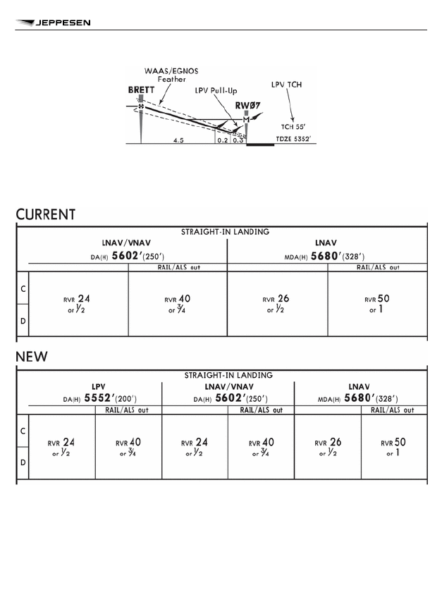
– Any applicable LPV related information will be added to the Ground Speed box.
– LPV landing minimums will be added to the landing minimums band. See the before and after

sample below:

IMPLEMENTATION

The addition of LPV landing minimums will begin starting in the 5 May 2017 revision. Conversion
will take place on an as revised basis.
Inquiries related to this Bulletin may be submitted through established customer support channels
or your account representative.

BRIEFING BULLETINS

33

FOR USERS OF THE COMMERCIAL AIRLINE FORMAT CHART (CAO) ONLY — LPV

MINIMUMS ADDED TO RNAV APPROACH PROCEDURES
PURPOSE

The purpose of this Bulletin is to announce enhancements to the graphical depiction of Jeppesen
taxi charts for Code F aircraft when a source provider has provided Jeppesen with the relevant
information regarding Code F taxi procedures at an aerodrome. Code F aircraft are aircraft with a
wingspan between 214ft (65m) and 263ft (80m) and outer main gear wheel span between 46ft
(14m) and 53ft (16m).
Moving forward, several enhancements will be applied which are intended to improve the overall
usability of Jeppesen taxi charts. These enhancements are a direct result of feedback received
from you, the customer, which Jeppesen greatly appreciates.

ENHANCEMENTS

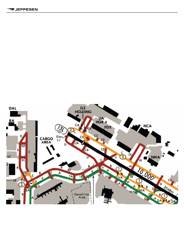
The sample graphic below depicts the enhancements being applied to Jeppesen Code F taxi
charts. A brief description of each major improvement is shown after the graphic.

Sample Plan View:

BRIEFING BULLETINS

34

CHART DESIGN ENHANCEMENTS OF TAXI CHARTS FOR CODE F AIRCRAFT

Sample Legend:

a. Colors have been changed to allow for a quicker and easier understanding of the aero-

drome.

– Green indicates an approved taxiway.
– Yellow indicates restrictions apply.
– Red indicates the taxiway is prohibited for use.

b. In the case multiple restrictions apply, a new ball flag type has been created to more easily

identify the restrictions.

c. A legend with appropriate information will be present on each chart to assist in further defin-

ing what each color and ball flag signifies.

d. Communications information, runway threshold information, and runway length will be shown

to reduce the need to switch between the standard airport diagrams.

IMPLEMENTATION PLAN

Jeppesen Code F taxi charts will be converted using the enhanced charting specifications begin-
ning with the 1 JUN 2018 revision.
Conversion will take place on an as-revised basis.
Inquiries related to this Bulletin may be submitted through established customer support channels
or your account representative.

BRIEFING BULLETINS

35

CHART DESIGN ENHANCEMENTS OF TAXI CHARTS FOR CODE F AIRCRAFT

THIS BULLETIN IS FOR INFORMATION ONLY. RETAIN OR DESTROY

AT YOUR DISCRETION.

BRIEFING BULLETINS

36

CHART DESIGN ENHANCEMENTS OF TAXI CHARTS FOR CODE F AIRCRAFT

PURPOSE

The purpose of this Bulletin is to announce the new Standard AOM concept and provide a general
description of the forthcoming changes concerning the way in which Jeppesen determines and
applies Aerodrome Operating Minimums (AOM) for landing and take-off to its worldwide library of
the Instrument Approach Procedures (IAP) and Airport charts in the Jeppesen Airway Manual.

BACKGROUND

Jeppesen has a long history as a global provider of aeronautical charts, navigation data and rela-
ted services. Among these essential services has been the uniform publication of Aerodrome
Operating Minimums on Airway Manual charts.
Jeppesen’s policy to recognize and respect the authority of individual State Aviation Authorities is
a fundamental principle past, present, and future.
The original Jeppesen Standard for AOM is known as the “Explanation of Common Airport Oper-
ating Minimum Specifications”, or ECOMS. This standard was significantly influenced by U.S.
FAA TERPS visibility tables which were widely accepted when ECOMS was originally created in
the late 1970s.
Over the years Jeppesen has been involved in initiatives to develop new, harmonized global AOM
concepts. These industry efforts led to the development of Joint Aviation Authorities JAR-OPS,
then EASA AIR OPS and in 2017 to the publication of the 4th edition of ICAO’s Doc 9365 Manual
of All-Weather Operations (AWOM). This was the genesis of the decision to replace the aged
ECOMS with a new Jeppesen AOM concept which is aligned with the new ICAO AWOM.

OBJECTIVES

The implementation of the new Standard AOM is intended to adopt accepted ICAO standards and
to better serve developments in aviation (such as Continuous Descent Final Approach flight tech-
nique, Approaches with Vertical Guidance, Enhanced Vision Systems, Performance Based Navi-
gation, etc.). It also leads to the presentation of the lowest possible visibility minimums which are
authorized by the State of the aerodrome.
The 

Jeppesen Standard AOM Policy for the depiction of operating minimums is:

a.

State-provided AOM will always be depicted as published by the State.
State-provided visibilities may be lower than the visibilities determined according to ICAO’s
AWOM. The determination of lower values by the State is not precluded by ICAO if such
values result in an acceptable level of safety. 

Therefore, the State-provided visibilities will

not being raised to match the visibilities from the tables in ICAO AWOM.
If the State does not provide AOM for “ALS out” condition, ALS out visibility values will be
determined according to the rules and tables in ICAO’s AWOM, but not below any State-pro-
vided visibilities for operational approach lights.
“Provided by State” means either, minimum visibilities are published on procedure source,
within the Aeronautical Information Publication (AIP), or a specific AOM concept has to be
applied within this State.

BRIEFING BULLETINS

37

GLOBAL APPLICATION OF NEW AERODROME OPERATING MINIMUMS (AOM) CONCEPT

b.

Where a State does not provide any AOM, Jeppesen will determine visibility values
according to the rules and tables in ICAO’s AWOM.

c.

Operators with tailored AOM concepts will continue to be accommodated in accordance
with the established processes.

SCOPE

The systematic conversion from ECOMS to the new Standard AOM will affect operators differ-
ently depending on the nature of their operations; domestic or international, country of origin, etc.
Operators, especially those who operate internationally, are encouraged to become familiar with
ICAO Doc 9365 AWOM with respect to possible implications. FAA and EASA approved operators
might be less affected because of the harmonization with ICAO.
The effects of replacing ECOMS-based visibility values with the new ICAO-based visibilities will
vary by State or by region.
In States where complete AOM are provided (such as United States), minimum visibility will typi-
cally remain the same. If the charted visibility was raised because of a higher ECOMS table value,
it is now being replaced by the lower State-provided visibility value.
In States that provide no or incomplete AOM, significant changes will apply on instrument
approach procedures charts. The new visibilities might be higher or lower than the charted ones.

OVERVIEW OF NEW JEPPESEN STANDARD AOM

MINIMUMS BOX LABEL

In the future, the new 

 label will apply to Jeppesen charts to indicate that the charted mini-

mums are determined according to the rules of the new Jeppesen AOM concept.

The current 

 label on existing charts, which indicates the AOM are according to EU-OPS/

EASA AIR OPS, will be replaced by 

.

Minimums with the 

 label are determined according to a State Regulation which pro-

vides rules 

similar to the ICAO AWOM. Deviations from ICAO AWOM will be described in ATC

State pages in the Airway Manual.
If the minimums are determined according to another AOM concept which is 

not similar to ICAO

AWOM, the State Regulation will be indicated by a different label:


minimums based on TERPS


State simply provides minimums, regulation/rules might be unknown


minimums based on JAR-OPS


minimums supplied with Military procedures

BRIEFING BULLETINS

38

GLOBAL APPLICATION OF NEW AERODROME OPERATING MINIMUMS (AOM) CONCEPT

SCENARIOS INVOLVING THE AVAILABILITY OF STATE-PROVIDED AOM FOR

LANDING

Descent Limit
The procedure source may include the following information to determine the descent limit for the
specific approach procedure:

a. DA, DH, DA(H) or MDA, MDH, MDA(H) or similar information;
b. OCA, OCH or OCA(H);

c. DA(H) or MDA(H) together with the procedure design OCA(H).

Guidelines for the determination of applicable Descent Limit values for landing minimums are out-
lined below.

Approach Type/

Condition

Source Provides

Descent Limit in Min-

imums Box labelled

as

Notes

Precision

(ILS, MLS, PAR, GLS,

LPV200, etc.)

DA, DH, DA(H)

DA(H)

Adjustments may be
made for rounded
source values.

APV

(LPV, LNAV/VNAV)

Precision

(ILS, MLS, PAR, GLS,

LPV200, etc.)

OCA, OCH, OCA(H)

DA(H)

The DA(H) is deter-
mined according to the
rules described in
ICAO AWOM.
Adjustments may be
made for rounded
source values.

APV

(LPV, LNAV/VNAV)

Non-precision

(LNAV, LP, LOC,

VOR, NDB, VDF, SRA,

etc.)

MDA, MDH, MDA(H)

MDA(H)

Depiction of MDA(H)
as descent limit is in-
dependent from us-
ing the CDFA or non-
CDFA flight techni-
que.
Adjustments may be
made for rounded
source values.

BRIEFING BULLETINS

39

GLOBAL APPLICATION OF NEW AERODROME OPERATING MINIMUMS (AOM) CONCEPT

Approach Type/

Condition

Source Provides

Descent Limit in Min-

imums Box labelled

as

Notes

Non-precision

(LNAV, LP, LOC,

VOR, NDB, VDF, SRA,

etc.)

DA, DH, DA(H)

DA(H)

It is assumed that a
height loss adjust-
ment is applied by
the State.
Adjustments may be
made for rounded
source values.

Non-precision

CDFA flight technique/

continuous descent

profile

(LNAV, LP, LOC,

VOR, NDB, VDF, SRA,

etc.)

OCA, OCH, OCA(H)

DA/MDA(H)

The DA/MDA(H) is de-
termined according to
the rules described in
ICAO AWOM and
does not include a
height loss adjust-
ment.
Adjustments may be
made for rounded
source values.

Non-precision

non-CDFA flight tech-

nique/stepped descent

profile

(LNAV, LP, LOC,

VOR, NDB, VDF, SRA,

etc.)

OCA, OCH, OCA(H)

MDA(H)

The MDA(H) is deter-
mined according to the
rules described in
ICAO AWOM.
Adjustments may be
made for rounded
source values.

HEIGHT LOSS ADJUSTMENT NOTES – APPLICABLE TO DA(H) MANEUVER ON NPA
Wherever a State authority has clearly prescribed, provided, or otherwise specified that a non-
precision instrument approach procedure has to be flown using the CDFA flight technique, 

and

the corresponding descent limit value is published by source as a DA(H), Jeppesen will assume
the State-provided DA(H) value includes a height loss adjustment. Only in this case the descent
limit would be charted as a DA(H) on a non-precision approach procedure.

BRIEFING BULLETINS

40

GLOBAL APPLICATION OF NEW AERODROME OPERATING MINIMUMS (AOM) CONCEPT


IMPORTANT NOTES:
Jeppesen will 
not add any Height Loss Adjustment to any charted DA/
MDA(H) or MDA(H) Descent Limit values unless specified by the State.
When using the CDFA flight technique and using a DA(H) in lieu of
MDA(H), 
operators must determine and apply an appropriate Height Loss
Adjustment applicable to the aircraft, landing configuration and/or oper-
ating requirements.

If it cannot be determined if the State has incorporated a Height Loss Adjustment, the ball note
below will be shown on applicable Non-Precision IAP approach charts. It is the operator’s respon-
sibility to provide necessary guidance to pilots.


“VNAV DA(H) in lieu of MDA(H) depends on operator policy.”


States may prescribe specific DA(H) height loss adjustment procedures for use when non-preci-
sion IAPs are flown using CDFA and DA(H) techniques. Such situations will be noted accordingly.
A note will be added to the straight-in landing minimums referencing any State-provided height
loss adjustment value or requirement.


IMPORTANT NOTE:
CDFA is a flight technique. It is not a procedure design criterion. Depend-
ing on varying regulatory operational requirements, for some operators
the use of CDFA for NPAs may be mandatory; for others it may be option-
al.


Visibility
States may not always provide visibilities for landing. The table below shows the rules which are
applied to determine the landing visibility:

Scenario

Rules

States provide visibilities for with and with-
out lights

– State-provided visibilities will be charted.

States provide visibilities for with approach
lights only
(approach lights are available and operational)

– State-provided visibilities will be charted.
– Visibilities for “ALS out” will be determined

according to ICAO AWOM, but not below the
State-provided values for operational lights.

BRIEFING BULLETINS

41

GLOBAL APPLICATION OF NEW AERODROME OPERATING MINIMUMS (AOM) CONCEPT

Scenario

Rules

States provide visibilities without lights only
(approach lights are not available or not opera-
tional at all)

– State-provided visibilities will be charted.

States provide no visibilities at all

– Visibilities will be determined according to

ICAO AWOM.

Visibilities will always be labelled as R (= RVR), V (= VIS), C (= CMV) or as R/V (= RVR and/or
VIS).

BRIEFING BULLETINS

42

GLOBAL APPLICATION OF NEW AERODROME OPERATING MINIMUMS (AOM) CONCEPT

Samples

SCENARIOS INVOLVING THE AVAILABILITY OF STATE-PROVIDED AOM FOR

TAKE-OFF

States may provide visibility minimums for take-off or not. The table below shows the rules which
are applied to determine the take-off visibilities:

BRIEFING BULLETINS

43

GLOBAL APPLICATION OF NEW AERODROME OPERATING MINIMUMS (AOM) CONCEPT

Scenario

Rules

States provide visibilities for with and without opera-
tional runway lights
(depending on lighting conditions, like HIRL + CL, CL,
RCLM, etc.)

– State-provided visibilities will be

charted.

States provide visibilities for operational runway lights
(lowest possible visibilities for best lights, no visibilities for
other conditions)
States provide visibilities without lights
States do not provide any visibilities for take-off

– Visibilities will be determined ac-

cording to ICAO AWOM.

Visibilities will always be labelled as R (= RVR), V (= VIS), C (= CMV) or as R/V (= RVR and/or
VIS).

Samples

CEILING

A Ceiling will only be charted for straight-in landing, circle-to-land or take-off minimums if prescri-
bed by the State authority as a parameter of the AOM they provide.

BRIEFING BULLETINS

44

GLOBAL APPLICATION OF NEW AERODROME OPERATING MINIMUMS (AOM) CONCEPT

SUPPLEMENTAL AOM TEXT PAGE LISTINGS

At certain airports, supplemental AOM text page listings (like 10-9S pages) have been published
in order to accommodate the needs of operators who require operating minimums that differ from
the AOM as depicted on the Standard Airway Manual charts.
With the implementation of the new Standard AOM concept most of these supplemental mini-
mums pages might become obsolete and will be removed accordingly.
However, the supplemental AOM text pages might still be required for airports where the State-
published minimums are lower than the AOM concept which is used by a specific operator.
An operator, who still needs supplemental AOM text pages, has to define the affected airports
and has to provide the AOM rules, same as for the current procedure.

IMPLEMENTATION PLAN

ICAO Annex 6 requires that the operator establishes airport operating minimums for each airport
to be used. This method needs to be approved by the State of the operator.
The publication of this Briefing Bulletin and the description of the new Standard AOM concept
allows you to become familiar with the changes and to analyze the impact on the operations
before the new concept is applied to the Airway Manual.
Jeppesen plans to start the publication of the new Standard AOM in 

January 2020.

All charts of an airport will be converted to the new concept at the same time. The conversion will
be done together with regular revision activities.
For customized charts we continue to determine the minimums according to the mini-
mums specifications which are agreed by the customer, only the depiction of the mini-
mums box will be changed to the new format.
Airports will be converted according to the priorities below:

a. Airports with pure ECOMS minimums where no State-provided minimums are available.

Existing 10-9S charts will be deleted during conversion.

b. Airports where ECOMS and State-provided minimums are charted.

Minimums will be converted to “State” and existing 10-9S pages will be updated to show the
higher of State and EASA AIR OPS.

c. Airports where “Standard”, “Standard/DGCA”, “TERPS” or “JAR-OPS” minimums are char-

ted.
These airports see almost no changes to the minimums, except the change to the new
format.

DOCUMENTATION

A detailed description of take-off and landing minimums based on the rules from ICAO AWOM
and their application on Jeppesen charts will be added into the Airway Manual (AWM) and to our
web site www.jeppesen.com/aom.

BRIEFING BULLETINS

45

GLOBAL APPLICATION OF NEW AERODROME OPERATING MINIMUMS (AOM) CONCEPT

The following documents are available with revision 23 AUG 19:

– Briefing Bulletin JEP 19-A;
– Jeppesen ATC-Chapter “Aerodrome Operating Minimums - Jeppesen” describing the rules and

tables for the new concept;

– Table comparing ICAO Doc 9365 AOM rules against EASA AIR OPS, Indian CAR, TERPS and

EU-OPS/CAR-OPS as part of the Jeppesen ATC chapter as mentioned above.

The following documents will be made available before January 2020:

– AOM scenarios and expected changes when converting to the new AOM concept (web site);
– State overview table to indicate which minimums concept will be applied for which State (web

site);

– Airport & Approach Chart Legend for take-off and landing minimums (Airway Manual and web

site).

Inquiries related to this Bulletin may be submitted through established customer support chan-
nels.

BRIEFING BULLETINS

46

GLOBAL APPLICATION OF NEW AERODROME OPERATING MINIMUMS (AOM) CONCEPT

Jeppesen is pleased to announce the redesign of the China High/Low Enroute Chart Series. The
redesign of these Enroute charts provides improved chart legibility and usability.
The new series of High/Low Altitude Enroute charts for China are planned for introduction in June
of 2020.
Improvements include:

– Improved chart scales (for new chart coverages, refer to graphic below):

• CH(H/L)1/2 

― 

1” = 30 NM, designed to accommodate flights in the north western and south

western regions of China.

• CH(H/L)3/4 

― 

1” = 20 NM, designed to accommodate flights towards the eastern regions of

China mainly for north/south direction.

• CH(H/L)5/6 

― 

1” = 20 NM, designed to accommodate flights along the eastern shores of

China mainly for north/south direction.

• CH(H/L)7/8 

― 

1” = 20 NM, designed to accommodate flights in the southern regions of

China.

– Improved chart scales will result in a cleaner depiction in areas of heavy congestion.
– Elimination of multiple chart insets to reduce the need for cross-referencing.
– Implementation of the Enroute chart enhancements which were announced with Bulletin Jep

17-A.

BRIEFING BULLETINS

47

CHINA HIGH/LOW ALTITUDE ENROUTE CHART SERIES REDRAW

To ease transition, Jeppesen will automatically replace charts in existing standard and tailored
chart coverages as follows:

– CH(H/L) 1/2 (old) replaced by CH(H/L) 1/2, 3/4, 7/8
– CH(H/L) 3/4 (old) replaced by CH(H/L) 3/4, 5/6, 7/8

Customers with tailored coverages are asked to review these chart coverage transitions and if
any changes are desired in their tailored coverage, please contact your Jeppesen Account Repre-
sentative no later than 15 MAY 20 to make appropriate changes. After 15 MAY 20 the standard
chart transitions listed above will be implemented to ensure complete coverage of aeronautical
information.

BRIEFING BULLETINS

48

CHINA HIGH/LOW ALTITUDE ENROUTE CHART SERIES REDRAW

Data extract cycles coincide with the AIRAC 28-day cycles used by Civil Aviation Authorities
worldwide. This includes Jeppesen’s Airport Mapping Database (AMDB) extracts that support Air-
port Moving Map (AMM) displays. All airport-related changes applicable to AMDB (additions,
changes and deletions) to be effective on a given AIRAC cycle date are included in the data
extract. Examples include physical changes to runways, taxiways, ramps, parking gates, as well
as changes to runway, taxiway, or gate markings.
Also included are interim changes based on NOTAMs or other official means that span at least
one AIRAC cycle. In certain cases, NOTAM changes that do not cover an entire AIRAC cycle but
terminate close to the cycle end date may be applied.
Jeppesen’s pre-composed Airway Manual chart customers can choose between 14- and 7-day
chart revision updates. As a result, certain chart-related interim changes may be issued more
quickly rather than the next 28-day cycle of the AMM. Additionally, Airport and Taxi charts are
updated for other items besides surface features. Examples include modifications to ATC commu-
nication frequencies, approach and runway lighting details, declared distances, take-off and alter-
nate minima, textual departure procedures, cultural features, and airport-related notes.
In some cases Airport/Taxi charts may not be revised immediately for minor changes and these
changes will be communicated via a Chart Change Notice. Even though there are situations that
may result in AMM displaying more up-to-date information, the pre-composed charts – in addition
to the relevant Chart Change Notices – should always be used as primary reference given the
completeness of the information. The AMM display should be used as a supplement to the Air-
port/Taxi charts which is particularly useful in improving situational awareness during ground
operations.
In regards to the features depicted on the AMM display such as NOTAMs which may not be avail-
able on the pre-composed chart due to the dynamic nature of the data, it is recommended to refer
to the AMM display and NOTAMs provided by your operations or via an official government
authority. For further details pertaining to the application of NOTAMs to pre-composed charts,
refer to Briefing Bulletin JEP 09-B dated 10 JUL 09. The bulletin is available within standard Jep-
pesen Airway Manual.
Should a discrepancy occur between Jeppesen products and official approved sources, the
nature of the discrepancy, including the impact on operations, is analyzed by Standards depart-
ment. The decision to issue an AMM Alert is made in accordance with established Alert criteria. In
certain cases, minor issues do not qualify the discrepancy as an Alert and will not be published as
an AMM Alert.
Jeppesen continues to work toward unification and synchronization between both products’ proc-
ess criteria in order to provide consistent updates regardless of the service demanded by the cus-
tomer.

BRIEFING BULLETINS

49

EXPLANATION OF AIRPORT MOVING MAP & AIRWAY MANUAL AIRPORT/TAXI CHART

PUBLICATION CYCLES

PURPOSE

The purpose of the bulletin is to announce enhancements to Jeppesen charts at military and joint
use locations. The description below shall enable the user to familiarize with the upcoming
changes.

BACKGROUND

In the past, Jeppesen procedure charts were primarily designed for the use by civil aviation oper-
ators. Going forward, the depiction of military procedures at military and joint use civil/military air-
ports will put increased focus on the needs of military pilots. With the introduction of several addi-
tional features and specification changes, this chart enhancement initiative will improve the usabil-
ity of Jeppesen charts for military operators.
The new chart specifications outlined below will first be released at DoD procedure charts being
added to the Jeppesen chart library starting in September. Existing military procedure charts will
be transitioned to the new specifications over time as part of the revision process.

ENHANCEMENTS

UHF COMMUNICATIONS

Ultra High Frequency (UHF) communications added at sole military and joint use, civil/military,
locations.

NAVAID SYMBOLS

Navaid symbols used will be those that are consistent with ICAO recommended symbols.

NAVAID BOXES

– Navaid boxes enhanced to include channel information and VHF frequency.
– Frequency/channel in the navaid box provides course guidance or formation radials.
– Frequency pairings designated in parenthesis.

BRIEFING BULLETINS

50

CHART DESIGN ENHANCEMENTS FOR MILITARY CHARTS

OFF CHART NAVAID DEPICTION

– Navaid type identified.
– Frequency/channel not in parenthesis provides course guidance or radial formation information.
– Frequency pairing designated in parenthesis.

CROSSING ALTITUDES IN THE CHART PLANVIEW

Altitude restrictions in the planview of charts will be enhanced in the following manner:

– Altitude crossing restrictions shown blue in color.
– Over-bar/under bars used to indicate the type of altitude restriction, following ICAO guidance.
– Between Altitudes/Flight Levels

– Minimum Altitude/Flight Level

BRIEFING BULLETINS

51

CHART DESIGN ENHANCEMENTS FOR MILITARY CHARTS

– Maximum Altitude/Flight Level

– Mandatory or At Altitude/FL

– Altitude/FL indicated by state source as recommended will be charted without over-bar and

under-bars

SPEED RESTRICTIONS IN THE CHART PLANVIEW

Speed restrictions in the planview on charts at military locations and joint use locations shown
using magenta color.

– Speed restrictions that apply to a specific navaid, intersection/waypoint; track segment, will be

placed next to, or tied to the element.

INSTRUMENT PROCEDURE DESIGN INDICATOR

In addition to indicating TERPS, PANS-OPS and MIPS, a NATL Procedure Design Indicator label
will be added to applicable procedures.
A NATL label represents a procedure designed according to ICAO (8168 guidance), PANS OPS
criteria, but the state has filed an exception to the design criteria for one of the following: Final
approach segment, missed approach segment or the circling area.
Example: Final; missed approach based on PANS OPS and the circling area has an exception
filed to the PANS OPS criteria. Therefore, the chart would indicate a NATL label.
Additionally, if the procedure AIP indicates the procedure design was based on mixed criteria,
TERPs and PANS OPS, the chart would indicate a NATL label.
NOTE: If a procedure has a NATL label, the AIP should be reviewed to determine the exception
the state has filed to the design criteria.

BRIEFING BULLETINS

52

CHART DESIGN ENHANCEMENTS FOR MILITARY CHARTS

OPR (OFFICE OF PRIMARY RESPONSIBILITY) LABEL

An OPR label will be included on all military procedure charts:

MIL (USAF) – procedures designed by the United States Air Force
MIL (USN) – procedures designed by the United States Navy
MIL (USA) – procedures designed by the United States Army
MIL – Any procedure based on a Host Nation military AIP

NOTE: If a procedure does not include an OPR label, the Host Nation has designed the proce-
dure.

MINIMUMS

– CAT E or HPMA minimums depicted when provided by source.
– Minimums depicted in the new Aerodrome Operating Minimums Format (AOM), refer to briefing

bulletin JEP 19-A dated August 23, 2019 on Jeppesen.com publications for additional informa-
tion.

BRIEFING BULLETINS

53

CHART DESIGN ENHANCEMENTS FOR MILITARY CHARTS

NOTE: Ceilings depicted on charts with a USAF, USN or USA OPR label apply only to military
operators. Military pilots should refer to appropriate regulations.

IMPLEMENTATION PLAN

– Jeppesen will begin adding approach procedures in the enhanced format and specifications

beginning September 2020.

– Existing approach charts at military and joint use civil and military locations will be updated over

time as part of the revision process.

CONTACT INFORMATION

– Inquiries related to this Bulletin may be submitted through established customer support chan-

nels or your account representative.

– Questions concerning the Jeppesen chart, or Electronic Chart Images, please contact Chart

Support:
+01 (303) 328-6776 (Western Hemisphere)
+49 (6102) 50-8174 (Eastern Hemisphere)
U.S. Toll Free: 1-800-353-2107
E-mail: ChartSupport@jeppesen.com

BRIEFING BULLETINS

54

CHART DESIGN ENHANCEMENTS FOR MILITARY CHARTS

Preface

Customer Service Bulletins

Jeppesen is committed to delivering the highest quality and most advanced products and services
in the industry. Our ongoing commitment to quality includes using various communication chan-
nels to disseminate the latest information that affects the Jeppesen products and services you
rely upon.
Updates are posted online at jeppesen.com under “Notices & Alerts.” Here you will also find RSS
feeds, which are an efficient way to monitor the latest information from Jeppesen. All Notices and
Alerts mentioned in this service bulletin can be subscribed to using RSS feed technology. Issues
related to our products or services are communicated using one or more standard notification
methods. The method we use depends on the product or service as well as the criticality of the
communication. The following is a brief description of our notification types:
NavData Alert 

1

NavData Alerts are used to inform commercial NavData subscribers, including airlines, avionics
equipment companies, and aviation service providers, of changes and issues related to databa-
ses distributed by Jeppesen. Alerts are intended to supplement the NavData Change Notices by
disseminating time-critical information that could have a significant affect on flight operations.
Alerts contain safety-of-flight or operationally significant information including but not limited to
incorrect turn directions, altitudes, bearing changes, etc. This information typically affects Jeppe-
sen's master database; however, each change or issue can be isolated to specific avionics equip-
ment. To determine whether the change or issue affects your database, you should check with
your individual avionics equipment manufacturer.
Chart Alert 

1

Chart Alerts are used to quickly disseminate flight critical information that affects Jeppesen's
Standard paper or electronic (JeppView) Airway Manual products. Occasionally, changes cannot
be issued to customers through our normal paper or electronic production schedules prior to
effectivity. Chart Alerts allow Jeppesen to immediately address these changes through either RSS
or our website as soon as they come to our attention.
Airport Moving Map (AMM) Alert 

1

Airport Moving Map Alerts are published to advise users of significant issues in Jeppesen Airport
Moving Map data that may affect aircraft ground operations. AMM Alerts allow Jeppesen to imme-
diately address these changes through either RSS or our website as soon as they come to our
attention.
Obstacle and Terrain Alerts 

1

Obstacle and Terrain Alerts are published to advise users of significant issues in Jeppesen
Obstacle or Terrain datasets. Obstacle and Terrain Alerts allow Jeppesen to immediately address
these issues through either RSS or our website as soon as they come to our attention.
Issues with obstacles and/or terrain that are displayed in individual products will be distributed in a
product-specific alert. For example, an issue with obstacle or terrain data on an approach chart
will be distributed in a Chart Alert and may not be distributed in an Obstacle and/or Terrain Alert.
NavData Change Notice 

2

CUSTOMER SERVICE BULLETINS

56

JEPPESEN ALERTS, NOTICES AND BULLETINS; DISSEMINATION OF PRODUCT-

RELATED INFORMATION

NavData Change Notices are directed at customers who receive Jeppesen NavData for use in
avionics equipment and flight planning systems, airline operations, and other systems that provide
aviation information. They are published weekly on jeppesen.com under “Notices & Alerts” and in
RSS feeds. They include updates and corrections to data and procedures that are not yet reflec-
ted in Jeppesen’s navigation databases. NavData Change Notices contain narrative explanations
of the changes that affect the data coded in Jeppesen’s current NavData cycle. Customers who
receive an Internet update service from Jeppesen will also receive NavData Change Notices as
part of their service.
Chart Change Notice 

2

Chart Change Notices are directed at customers who receive Jeppesen Terminal and Enroute
charts. They are included in the revision updates that are mailed to customers and are also
posted on jeppesen.com under “Notices & Alerts” and RSS feed. Each notice contains a narrative
explanation of changes affecting the current Jeppesen chart. Jeppesen Chart Change Notices
highlight only significant changes affecting Jeppesen Charts. A Graphic Chart Change Notice may
be issued to depict a more significant change to a Jeppesen Enroute or Area chart. A Chart
Change Notice will remain in effect until the chart is to be reissued.
On-Demand Change Notice 

2

On-Demand Change Notices are available on jeppesen.com in the Main page and under the Noti-
ces and Alerts page. They contain the same content that both NavData and Chart Change Noti-
ces contain. However, unlike NavData and Chart Change notices, On-Demand Change Notices
are updated when our Change Notices Database is updated (near real-time). On-Demand
Change Notices also allows the user the ability to search Change Notices for a single Airport or
FIR.
NavData Notice
NavData Notices are issued to airframe and avionics equipment manufacturers to announce addi-
tional database capabilities or new datasets that will affect the output of navigational data. Nav-
Data Notices are intended for Jeppesen's Original Equipment Manufacturer (OEM) partners only.
Jeppesen’s Product Management department may also issue notices highlighting any changes
made to Jeppesen Internet update services, such as data content, modifications to data card
sizing, or system-specific information issued by an avionics equipment manufacturer. End users
of the data may contact their avionics equipment providers with questions regarding the availabil-
ity of data in their specific units.
Briefing Bulletin
Briefing Bulletins provide you with explanations of modifications to Jeppesen products that are
being implemented in response to changes suggested by customers or required by governing
authorities. In particular, Briefing Bulletins explain how changes will affect Jeppesen's products.
Customer Service Bulletin
Customer Service Bulletins contain information that educates you on the content of our products
and services. Additionally, Customer Service Bulletins may be issued to inform customers about

CUSTOMER SERVICE BULLETINS

57

JEPPESEN ALERTS, NOTICES AND BULLETINS; DISSEMINATION OF PRODUCT-

RELATED INFORMATION

major events where significant short-term changes or restrictions to flight operations will be in
effect.

1 Beginning November 2012, Alerts will only be distributed to our customers through RSS Feeds. To learn more about this subject,

please see our 03 Aug 2012 Customer Service Bulletin.

2 When Charts and/or NavData are intentionally omitted from Jeppesen Airway Manual or NavData respectively, Change Notices

will include that information along with the respective revision/cycle that the information will be included.

Please note that the Customer Notification Services defined above only refer to Jeppesen prod-
ucts and do not replace State-published NOTAMs.
All communication channels listed above are posted on jeppesen.com under the “Notices &
Alerts” section.
We hope this bulletin clarifies the various product and service updates you may receive from Jep-
pesen. If you have any questions please contact your account representative or customer service
at:

The Americas

800.621.5377

E-mail: captain@jeppesen.com

Europe & Asia

+49 6102 5070

E-mail: fra-services@jeppesen.com

United Kingdom, Middle East & Africa

+44 1293 842404

0800 085 5377 (UK & Ireland)

E-mail: uk-services@jeppesen.com

Australia

+61 2 6120 2999

E-mail: customerservice@jeppesen.com.au

Sincerely,
Jeppesen Corporate Technical Standards and Product Management

CUSTOMER SERVICE BULLETINS

58

JEPPESEN ALERTS, NOTICES AND BULLETINS; DISSEMINATION OF PRODUCT-

RELATED INFORMATION

Jeppesen distributes notices related to our products and services using several standard notifica-
tion methods. One of these methods includes issuing time-critical information using Jeppesen
Notices & Alerts through https://www.jeppesen.com. Here you’ll find Notices & Alerts that can
impact your flight or operations. In addition to our Notices & Alerts page, we also distribute alerts
using RSS (Really Simple Syndication) feeds, which is an alternate way to monitor the latest Jep-
pesen product & charting information.
Beginning January 17, 2020, Jeppesen will transition to a new Notices & Alerts page. If you moni-
tor Notices & Alerts via an RSS feed, please note that you may need to resubscribe to continue
receiving RSS notifications by reinstalling a compatible RSS plug-in application. This will ensure
you continue to receive the broadcasting of any new Alert notifications from Jeppesen’s website.
In addition to online Alerts, RSS feeds can be used to automatically customize the broadcasting
of Alerts by region applicable to a designated geographic location.
To subscribe to RSS feeds, simply download a compatible RSS viewer (e.g., Feedly & RSSOlw)
of your choice, then follow the steps below.
Go to https://www.jeppesen.com

Select “Company”

Select “Notices And Alerts” at the top of the home page.


On the left side of the page, you’ll have the option of selecting a single region, or filtering down to
a sub-region and the Category of the alert type.
Follow these steps, if you would like to subscribe to a specific region:

CUSTOMER SERVICE BULLETINS

59

CHANGE IN RSS FEED FOR JEPPESEN NOTICES & ALERTS

Click on the “Region” dropdown and select a Region from the list.

Select a “Sub-Region” from the drop down.

Choose the “Category” of Alert you are interested in subscribing to:


Once the preferred Region and Subregion is selected, click the RSS link, as shown in
step 6. You should see a prompt from your preferred RSS application. Follow the sug-
gested RSS application steps as suggested by your selected RSS application.

NOTE: (To subscribe to multiple subregions, you’ll need to repeat steps 1 through 6.)

That’s it! Now the RSS feed will automatically show you any new Notices and Alerts so you’ll
always have the latest information. It will be customized so that you only get the information that
is relevant to you.
We hope this bulletin clarifies the steps necessary to set up the new RSS Feeds. If you have any
questions, please go to Jeppesen.com/Contact Us (https://www.jeppesen.com/contact-us/) or by
calling:
Jeppesen Support:
Tel:

Toll-Free: 1-800-732-2800
Direct: 1-303-328-4587

Sincerely,
Jeppesen Aviation Technical and Regulatory Standards

CUSTOMER SERVICE BULLETINS

60

CHANGE IN RSS FEED FOR JEPPESEN NOTICES & ALERTS

Introduction

Introduction

Definitions and Abbreviations

AIRPORT QUALIFICATION PAGES

U.S. Federal Aviation Regulations (FAR) Part 121.445 specifies pilot in command special airport
qualifications. The (FAA) Administrator may determine that certain airports (due to items such as
surrounding terrain, obstructions, or complex approach or departure procedures) are special air-
ports requiring special airport qualifications. These requirements do not apply when an entry to
that airport (including a takeoff or a landing) is being made if the ceiling at that airport is at least
1,000 feet above the lowest MEA or MOCA, or initial approach altitude prescribed for the instru-
ment approach procedure for that airport, and the visibility at that airport is at least 3 miles.
At other times, no certificate holder may use any person, nor may any person serve, as pilot in
command to or from an airport determined to require special airport qualifications unless, within
the preceding 12 calendar months:

a. The pilot in command or second in command has made an entry to that airport (including a

takeoff and landing) while serving as a pilot flight crewmember; or

b. The pilot in command has qualified by using pictorial means acceptable to the Administrator

for that airport.

Airport qualification pages, when approved by the certificate holder’s Principal Operations Inspec-
tor (POI), provide an acceptable means of complying with the above requirement.
The list of special airports is found in the Handbook Bulletin for Air Transportation (HBAT) 03-07.
The list is also accessible through the following web site:
http://www.opspecs.com/ops/SpecialPICAirports/

AIRPORT FAMILIARIZATION PAGES

Airport familiarization pages are similar to qualification pages, except the familiarization airports
are not currently considered a special airport under FAR 121.445. However as with qualification
pages, familiarization pages depict airports that are also unique due to items such as surrounding
terrain, obstructions, or complex approach or departure procedures.

ICAO

DOC 7300, Annex 6 specifies that a pilot in command must be currently qualified to be used on a
route or route segment. Each such pilot shall demonstrate to the operator an adequate knowledge
of aerodromes which are to be used including such things as knowledge of terrain, minimum safe
altitudes, and seasonal meteorological conditions. In another provision, an operator may qualify a
pilot in command to land at an aerodrome by means of an adequate pictorial presentation.
According to the state authority's recommendation or on the operator's individual decision, both
airport qualification and airport familiarization pages can be used for professional familiarization of
specific airports.

DESCRIPTION OF SERVICE

The front side of the overview page provides an aerial image of the airport. The overview image
will include key areas of interest surrounding the airport, such as obstructions that could affect
flight operations. Below the image is a graphic presentation of the airport and surrounding area.

DEFINITIONS AND ABBREVIATIONS

63

AQ

The graphic portion includes airways, navigation aids, general terrain contours, water, roads and
city patterns. The graphic also includes an overview arrow that indicates the direction from which
the image is viewed.
The reverse side of the overview page provides a textual description of the airport and its sur-
rounding area. The textual description points out key items of interest about the airport, as well as
the surrounding area. An annual weather table is also provided on the second half of the page.
This table is based on seasonal data and represents average monthly values.
Runway pages portray the airport’s primary runways. The top portion of the page provides a view
of the approach end of the runway, as seen during the landing phase of flight. Below is a narrative
that provides specific information and unique features relating to the runway. The reverse side of
the page provides the same type of information for the opposite end of the runway.
All airport pages are updated as significant changes dictate. In addition, Airport Qualification loca-
tions are reissued every 24 months.

DEFINITIONS AND ABBREVIATIONS

64

AQ


Content      ..      1      2      3      ..