Saf-T-Liner C2 School Bus. Driver’s Manual (2012) - page 2

Hydraulic and Air Brake Systems
Shutting Down the Engine
Make sure the exhaust brake switch is turned off be-
fore shutting down the engine.
10.7

11
Pre- and Post-Trip
Checklists
Pretrip and Post-Trip Inspection General Information
11.1
Daily Pretrip Inspection and Maintenance Checklist
11.2
Weekly Post-Trip Inspection and Maintenance Checklist
11.3
Monthly Post-Trip Inspection and Maintenance Checklist
11.3

Pre- and Post-Trip Checklists
Pretrip and Post-Trip
Inspection General Information
Regulations in Canada and the U.S. clearly indicate
that it is the driver’s responsibility to perform an in-
spection, and ensure the complete road-worthiness
of a vehicle, before placing it into service. Commer-
cial vehicles may be subject to inspection by autho-
rized inspectors, and an unsafe vehicle can be taken
out of service until the driver or owner repairs it.
Use the following checklists to ensure that vehicle
components are in good working condition before
each trip. Careful inspections eliminate stops later to
fix overlooked or forgotten items.
Numbers within each of the checklists reference the
corresponding detailed instructions found under the
daily, weekly, or monthly inspection and maintenance
procedures in Chapter 12.
If any system or component does not pass this in-
spection, it must be corrected before operating the
vehicle. Whenever equipment requires adjustment,
replacement, repair, addition of lubricants, or a
change of lubricants, see the Saf-T-Liner C2 School
Bus Workshop Manual for procedures and specifica-
tions, or take the vehicle to an authorized Freightliner
dealer.
IMPORTANT: The pretrip and post-trip checklists
in this chapter, and the maintenance procedures
detailed in Chapter 12 and in the Saf-T-Liner
C2 School Bus Maintenance Manual are not all
inclusive. Also, refer to the inspection and
maintenance instructions of the major compo-
nent manufacturers.
11.1

Pre- and Post-Trip Checklists
See Table 11.1 for a checklist of the procedures that
Daily Pretrip Inspection and
should be performed daily, before the first trip.
Maintenance Checklist
IMPORTANT: Before performing any checks,
apply the parking brake and chock the tires.
Procedure Performed
Procedure
Daily Pretrip Inspections/Checks
(check off)
Reference
drain manually drained air reservoirs (that are not equipped with automatic drain
_______
1
valves)
Check
_______
surge tank coolant level
2
Inspect
_______
radiator and charge air cooler
3
Inspect
_______
engine for fuel, oil, or coolant leaks
4
Check
_______
intake-air restriction indicator and air intake system
5
Check
_______
engine oil level
6
Check
_______
automatic transmission fluid level, if equipped
7
Check
_______
fuel/water separator, if equipped
8
Inspect
_______
fuel tank(s), fuel lines, and connections
9
Check
_______
fuel level
10
Check
_______
clean diesel engine fuel cap vent area
10
Check
_______
front and rear suspension components
11
Check
_______
reset dash-mounted air intake restriction indicator
12
Check
_______
air-pressure warning system
13
Check
_______
horn
14
Check
_______
backup alarm, if equipped
-
Check
_______
exterior lights
15
Inspect
_______
air brake chambers and pushrods
16
Inspect
_______
slack adjusters
17
Check
_______
tire pressure
18
Inspect
_______
tire condition
19
Check
_______
rims and wheels
20
Check
_______
air brake system
21
Check
_______
parking brake
22
Inspect
_______
frame rails (missing bolts), crossmembers (bent or loose)
-
mud flaps (aren’t damaged, at least 10 inches above the ground, and brackets
Check
_______
-
are secure)
exhaust system (mounted securely, connected tightly, no signs of leaks such as
Check
_______
-
soot trails)
Inspect
_______
Bendix Hydro-Max® Power Booster , if equipped
23
Inspect
_______
engine and chassis wiring
24
Inspector___________________________________________________ Date ________________
Table 11.1, Daily Pretrip Inspection and Maintenance Checklist
11.2

Pre- and Post-Trip Checklists
See Table 11.2 for a checklist of the procedures that
Weekly Post-Trip Inspection
should be performed weekly, post-trip.
and Maintenance Checklist
IMPORTANT: Before performing any checks,
apply the parking brake and chock the tires.
Procedure Performed
Procedure
Weekly Post-Trip Inspections/Checks
(check off)
Reference
_______
manually drain air reservoirs that are equipped with automatic drain valves
—
Inspect
_______
batteries and battery cables
1
Check
_______
wheel bearing lubricant level
2
Inspect
_______
steering components
3
Check
_______
drive belt conditions
4
Check
_______
air restriction indicator
5
Inspect
_______
seat belts and tether belts
—
Inspector___________________________________________________ Date ________________
Table 11.2, Weekly Post-Trip Inspection and Maintenance Checklist
See Table 11.3 for a checklist of the procedures that
Monthly Post-Trip Inspection
should be performed monthly, post-trip.
and Maintenance Checklist
IMPORTANT: Before performing any checks,
apply the parking brake and chock the tires.
Procedure Performed
Procedure
Monthly Post-Trip Inspections/Checks
(check off)
Reference
_______
clean the battery terminals
1
Check
_______
fluid level in the hydraulic clutch reservoir, if equipped
2
Check
_______
steering wheel play
3
outer surfaces of the hood and body (for visible surface breaks and damage, as
Check
_______
—
well as corrosion and paint condition)
Inspect
_______
brake lining wear
4
Inspect
_______
driveshaft
—
Inspect
_______
condition of floor covering and upholstery
—
Check
_______
operation of roof hatches and warning buzzers
—
Check
_______
operation and locking of emergency doors
—
Inspect
_______
wiper blades
—
Inspect
_______
body mounting bolts and clips securely fastened
5
_______
clean the bus undercarriage
6
Inspector___________________________________________________ Date ________________
Table 11.3, Monthly Post-Trip Inspection and Maintenance Checklist
11.3

12
Pre- and Post-Trip
Inspections and
Maintenance
Daily Pretrip Inspection and Maintenance Procedures
12.1
Weekly Post-Trip Inspection and Maintenance Procedures
12.9
Monthly Post-Trip Inspection and Maintenance Procedures
12.11
Pre- and Post-Trip Inspections and Maintenance
1.2
Exhaust the remaining air and moisture
Daily Pretrip Inspection and
from the system by opening the drain
Maintenance Procedures
cocks on the bottom of the remaining air
reservoirs. Block the valves open.
IMPORTANT: If any system or component does
not pass this inspection, it must be corrected
NOTICE
before operating the vehicle. Whenever equip-
ment requires adjustment, replacement, and/or
Coolant must be filled to the COLD MAX line of
repair, see the Saf-T-Liner C2 School Bus Work-
the surge tank. Low coolant could result in en-
shop Manual for procedures and specifications.
gine overheating, which could cause engine dam-
age.
Complete the following inspection and maintenance
procedures to ensure that vehicle components are in
2. Check the engine coolant level in the radiator
good working condition before each trip. A driver who
surge tank.
is familiar with the vehicle and drives it regularly can
perform the daily inspections, then add the weekly
If the coolant is low, fill the surge tank to the
and monthly post-trip inspections as scheduled.
MAX line with a 50/50 mixture of water and the
type of antifreeze currently installed in the ve-
If the driver does not operate the vehicle on a con-
hicle. See Fig. 12.1. For a list of approved cool-
sistent basis, all daily, weekly, and monthly inspec-
ants for both diesel and liquid propane gas
tion and maintenance procedures should be per-
(LPG) engines, see Table 12.1. If the surge tank
formed before the trip.
was empty, start the engine after refilling and
check the level again when the engine is at oper-
IMPORTANT: The pre- and post-trip checklists,
ating temperature.
inspections, and maintenance procedures de-
tailed in this chapter are not all-inclusive.
Refer to other component and body manufactur-
ers’ instructions for specific inspection and
maintenance instructions, as well as local, state,
and federal guidelines.
1. Drain the brake system air reservoirs (reservoirs
without automatic drain valves only).
Water and oil normally enter the air reservoir in
the form of vapor because of the heat generated
during compression. After the water and oil con-
dense, drain the resulting emulsion as follows:
1.1
Open the wet tank valve. The drain cock
or pull chain drain is located on the for-
ward end of the supply air reservoir, which
05/31/2007
f200705
is connected directly to the air compres-
sor. Block the valve open.
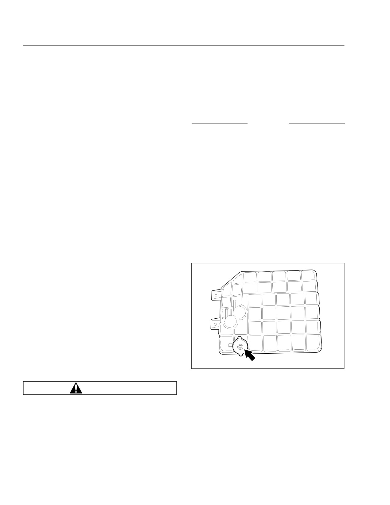
Fig. 12.1, Surge Tank Fill Cap
WARNING
When draining the air reservoir, do not look into
the air jets or direct them toward anyone. Dirt or
sludge particles may be in the airstream and
could cause injury.
12.1
Pre- and Post-Trip Inspections and Maintenance
3.6
Make sure the heater hoses are pliable
Approved Coolants
and are not cracking or ballooning.
Coolant
EngineType
Coolant Manufacturer
Designation*
3.7
Tighten hose clamps as necessary.
Old World Industries
Fleet Charge®
IMPORTANT: Do not overtighten hose
Shell HD/N
Shell
clamps, as hose life can be adversely af-
Antifreeze
Diesel
fected.
Texaco
JC04 Antifreeze
Van Waters and
Diesel Antifreeze
3.8
Ensure hose support brackets are se-
Rogers Ltd. (Canada)
No. 6038
curely fastened. Make sure hoses are not
Chevron Delo
located near sources of wear, abrasion, or
Propane
Chevron
Antifreeze No.
high heat.
275110†
IMPORTANT: When replacing hoses, install
* Freightliner-approved antifreeze must meet one of the following condi-
tions: A. Ethylene glycol solution that meets GM 6038-M Engineering
service-type knitted or braided yarn-
Standards. B. Ethylene glycol solution that has less than 0.1% anhydrous
sodium metasilicate and meets either GM 1825-M or GM 1899-M Engi-
reinforced neoprene hose. Extended-service-
neering Standards.
life silicone hoses may also be used. See
†
Chevron Delo coolant is approved for use in LPG engines only.
the Alliance Parts Catalog at www.alliance-
Table 12.1, Approved Coolants
brandparts.com or contact a Freightliner
dealer.
3.
Inspect the radiator and charge air cooler, includ-
4. Check the ground underneath the engine for fuel,
ing the radiator and heater hoses, clamps and
oil, or coolant leaks. Correct any leaks found.
support brackets.
5. Inspect the air intake system for leaks or dam-
3.1
Inspect the radiator and charge air cooler
age.
for clogged fins. Use compressed air or
water directed from the fan side of the
core to backflush any material restricting
NOTICE
airflow.
Failure to maintain a sealed air intake system
3.2
Inspect the radiator and charge air cooler
could allow the entry of dirt and contaminants
for damage and accumulated debris.
into the engine. This could adversely affect en-
Straighten bent or damaged fins to permit
gine performance and result in engine damage.
airflow across all areas of the cores.
5.1
Push the reset button on the air intake
NOTE: When traveling through areas of high
restriction indicator located on the air
insect concentration, it may be necessary to
cleaner, if equipped.
clean the exterior of the radiator or the
5.2
Check the air intake duct from the air
charge air cooler core as often as every 200
cleaner to the engine intake. Make sure
miles (322 km).
the duct components are secure and air-
3.3
Inspect and clean the condenser. If
tight.
clogged, the condenser can restrict airflow
through the radiator.
NOTICE
3.4
Check the radiator for leaks. If leaks are
Operating the engine with the oil level below the
found, have the radiator repaired or re-
minimum fill (or "add") mark or above the maxi-
placed. See Group 20 of the Saf-T-Liner
mum fill (or "full") mark could result in engine
C2 School Bus Workshop Manual for in-
damage.
structions, or take the vehicle to an autho-
rized Freightliner dealer for assistance.
IMPORTANT: On engines that comply with
3.5
Make sure the radiator inlet and outlet
EPA07 or newer regulations, use CJ-4 engine
hoses are pliable and are not cracking or
oil with less than 1% sulfated ash. Failure to
ballooning.
12.2
Pre- and Post-Trip Inspections and Maintenance
use CJ-4 oil may void the warranty on emission
aftertreatment components.
6. Check the engine oil level.
NOTICE
Operating the engine with the oil level below the
08/05/2010
f012186
minimum fill (or "add") mark or above the maxi-
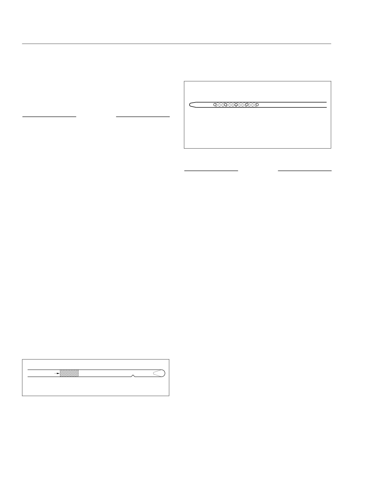
Oil should be within the cross-hatched area of the
mum fill (or "full") mark could result in engine
dipstick.
damage.
Fig. 12.3, Oil Dipstick (propane engine)
6.1
Park the vehicle on a level surface. Allow
several minutes for the oil to drain back
NOTICE
into the oil pan to ensure an accurate
reading.
Failure to use the recommended oil can result in
NOTE: For diesel engines, follow the engine
engine or aftertreatment component damage and
manufacturer’s guidelines for engine shut-
will void the warranty.
down time requirements prior to checking
7.
If the vehicle is equipped with an automatic
the oil level.
transmission, check the automatic transmission
fluid level.
6.2
Pull out the dipstick and clean it with a
paper towel or cloth, then push the dip-
NOTE: The fluid must be warm to ensure an
stick back in all the way. Remove it again,
accurate check. The fluid level rises as tem-
keeping the tip down, and check the oil
perature increases.
level.
7.1
Operate the transmission in a Drive (D)
6.3
If the oil is below the cross-hatched area,
range until normal operating temperature,
or the add mark, at the tip of the dipstick,
160 to 200°F (71 to 93°C), is reached.
add at least one quart (liter) of the recom-
mended oil. See Fig. 12.2 for diesel en-
7.2
With the parking brake applied, shift to
gines and Fig. 12.3 for propane engines.
Neutral (N). Let the engine run at idle.
For diesel engines that comply with
7.3
Wipe the dipstick clean and check the
EPA07 or newer regulations, use CJ-4
fluid level. A safe operating level is any
engine oil with less than 1% sulfated ash.
level within the HOT-run (upper) band on
the dipstick. See Fig. 12.4.
For liquid propane gas (LPG) engines, use
SAE 5W-30 oil that meets GM standard
7.4
If the fluid is not within this range, add or
GM6094M and has the American Petro-
drain fluid as needed to bring the level to
leum Institute (API) symbol. Do not use
the top of the HOT-run band.
SAE 10W-40 or 20W-50.
8.
Check for water in the fuel/water separator, if
equipped.
FULL
ADD 2 QT
IMPORTANT: When draining fluid from a
fuel/water separator, drain the fluid into an
appropriate container and dispose of it prop-
10/26/2012
f012203
erly. Many jurisdictions now issue fines for
Fig. 12.2, Oil Dipstick (diesel engine)
draining fuel/water separators onto the
ground.
8.1
Place a suitable container under the fuel/
water separator.
12.3
Pre- and Post-Trip Inspections and Maintenance
6
5
4
3
7
A
2
B
8
02/27/2002
f270077
1
A. Hot-Run Band
B. Cold-Run Band
9
Fig. 12.4, Automatic Transmission Dipstick Markings
10
NOTE: A hose may be used to direct water
into the container. Use a hose with a 1/2-
inch pipe thread on DAVCO models.
11
8.2
If the engine is equipped with a built-in
02/03/2010
f470552
water separator, loosen the drain valve,
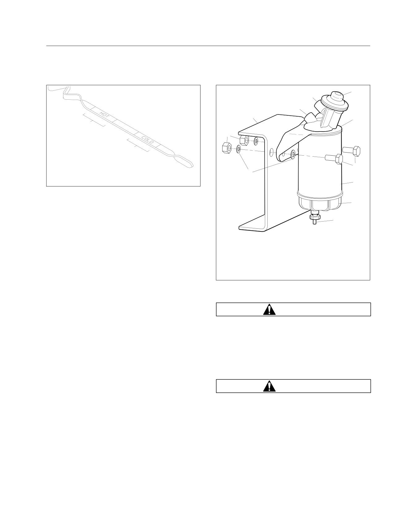
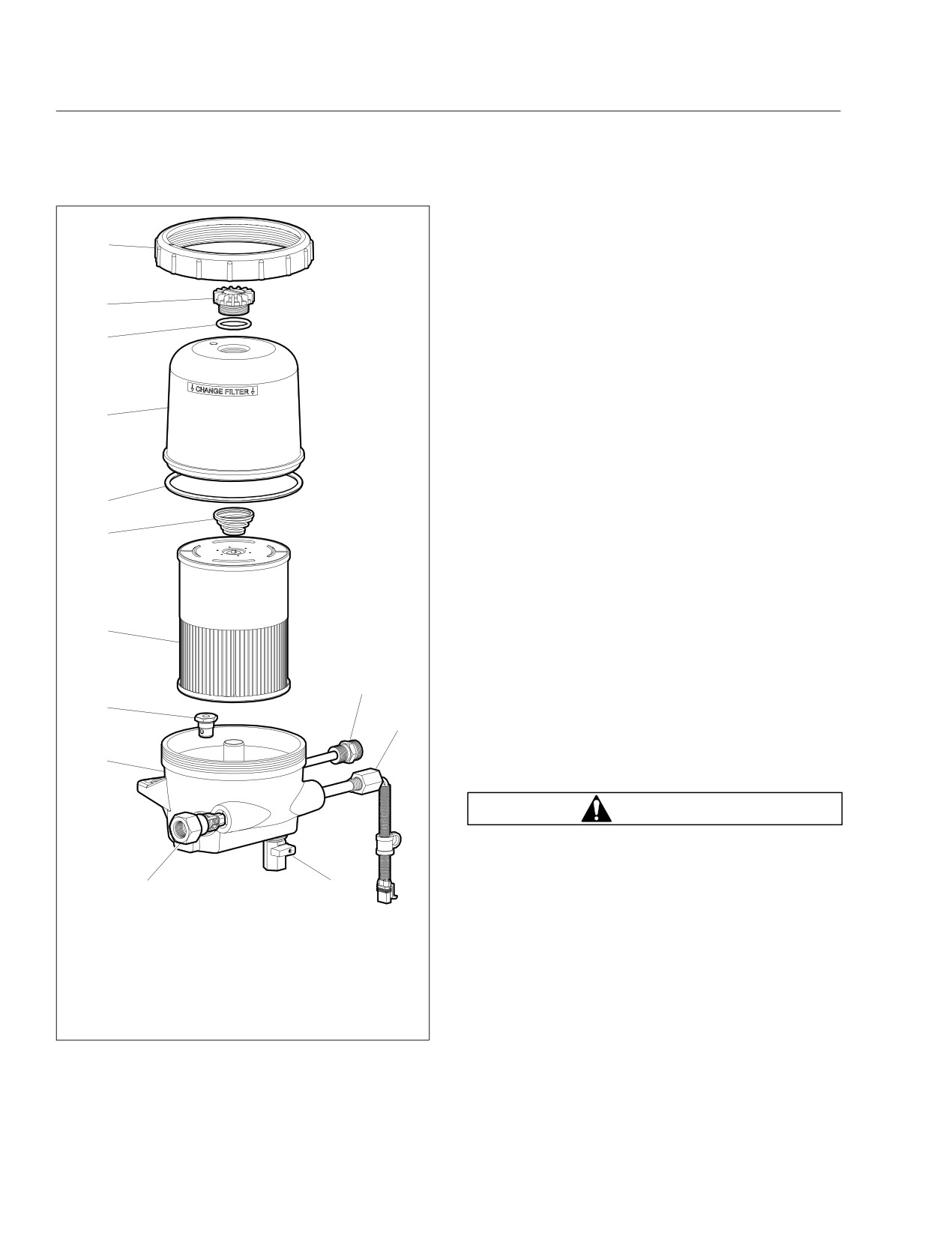
1. Washers (qty 2)
7. Mounting Head
and allow the water to run out. Close the
2. Nuts (qty 2)
8. Mounting Bolts (qty 2)
drain valve, taking care not to overtighten
3. Frame Rail
9. Filter Element
it.
4. Fuel Outlet Port
10. Sight Bowl
5. Fuel Inlet Port
11. Drain Plug
8.3
Alliance/Racor Models: Turn the drain plug
6. Priming Pump
counterclockwise to open it. See
Fig. 12.5.
Fig. 12.5, Alliance Fuel/Water Separator Assembly and
Installation
DAVCO Models: Remove the vent cap
and open the drain. See Fig. 12.6.
WARNING
8.4
Stop draining fluid when fuel begins to
drain out.
Never operate the engine with the fuel tank shut-
Alliance/Racor Models: Turn the drain plug
off valves partly closed. This could damage the
clockwise to close it.
fuel pump, causing sudden loss of engine power,
possibly resulting in serious personal injury due
DAVCO Models: Close the drain valve.
to reduced vehicle control.
Install and hand-tighten the vent cap.
9.4
If equipped with fuel tank shutoff valves,
9.
Inspect the fuel tanks, fuel lines, and connec-
be sure the valves are fully open.
tions.
9.1
Ensure fuel tanks are secured to their
WARNING
mounting brackets and that the mounting
brackets are secured to the frame.
Never fill fuel tanks to more than 95 percent of
9.2
Replace leaking fuel tanks.
their liquid capacity. This could make them more
likely to rupture from impact, possibly causing
9.3
If lines or connections are leaking or
fire and resulting in serious personal injury or
chafed, have them repaired or replaced.
death by burning.
Do not mix gasoline or alcohol with diesel fuel.
This mixture could cause an explosion, possibly
12.4
Pre- and Post-Trip Inspections and Maintenance
resulting in serious personal injury or death. Do
not fill the fuel tanks in the presence of sparks,
10
open flames, or intense heat. These could ignite
the fuel, possibly causing severe burns.
IMPORTANT: On engines that comply with
9
EPA07 or newer regulations, use ultralow-sulfur
diesel (ULSD) with 15 ppm sulfur content or
8
less. Failure to use ULSD fuel may void the
warranty on emission components.
10. Check the fuel level in the fuel tank(s). To keep
condensation to a minimum, fuel tanks should be
7
filled at the end of each day.
On vehicles equipped with a diesel engine, be
sure that the fuel cap vent area is clean.
11. Inspect the front and rear suspension compo-
6
nents, including springs, spring hangers, shocks,
and suspension brackets.
5
11.1
Check for broken spring leaves, loose
U-bolts, cracks in the suspension
brackets, and loose fasteners in the spring
hangers and shackles.
4
11.2
Inspect the shock absorbers for loose fas-
teners and leaks.
11.3
Tighten all loose fasteners and have any
11
components replaced that are worn,
3
cracked, or otherwise damaged.
12
11.4
On vehicles with air suspensions, check
for leaks. Check air suspension compo-
2
nents for cuts and bulges.
WARNING
Do not replace individual leaves of a damaged
front or rear suspension leaf spring assembly;
replace the complete spring assembly. Visible
1
13
damage, such as cracks or breaks, to one leaf
05/05/2009
f470530
causes hidden damage to other leaves. Replace-
1. Inlet Port/Check Valve
8.
Vent Cap O-Ring
ment of only the visibly damaged part(s) is no
2. Lower Housing
9.
Vent Cap
assurance that the spring is safe. If cracks or
3. Bypass Valve
10. Collar
breaks exist on front spring assemblies in either
4. Filter Element
11.
120VAC Pre-Heater
of the two top leaves, a loss of vehicle control
5. Spring
12.
12VDC Pre-Heater
could occur. Failure to replace a damaged spring
6. Cover O-Ring
13. Drain Valve
assembly could cause an accident resulting in
7. Clear Cover
serious personal injury or property damage.
Fig. 12.6, DAVCO Fuel/Water Separator (Fuel Pro 482
12. Push the reset button on the dash-mounted air
shown)
intake restriction indicator, if equipped.
12.5
Pre- and Post-Trip Inspections and Maintenance
13.
With the ignition switch in the OFF position,
check the air-pressure warning system.
13.1
If not previously drained, drain the air res-
ervoirs using moderate brake applications
until pressure in both reservoirs is less
than 70 psi (483 kPa).
13.2
Turn the ignition switch to the ON/RUN
position. The ICU will complete a full
gauge sweep and bulb check, and an au-
dible warning will sound. Ensure the low
air pressure lamp (BRAKE AIR) remains
illuminated and an audible warning contin-
ues to sound after the gauge sweep is
complete.
14.
Make sure that the electric horn works.
05/27/2011
f545785
15.
Make sure all the exterior lights are working.
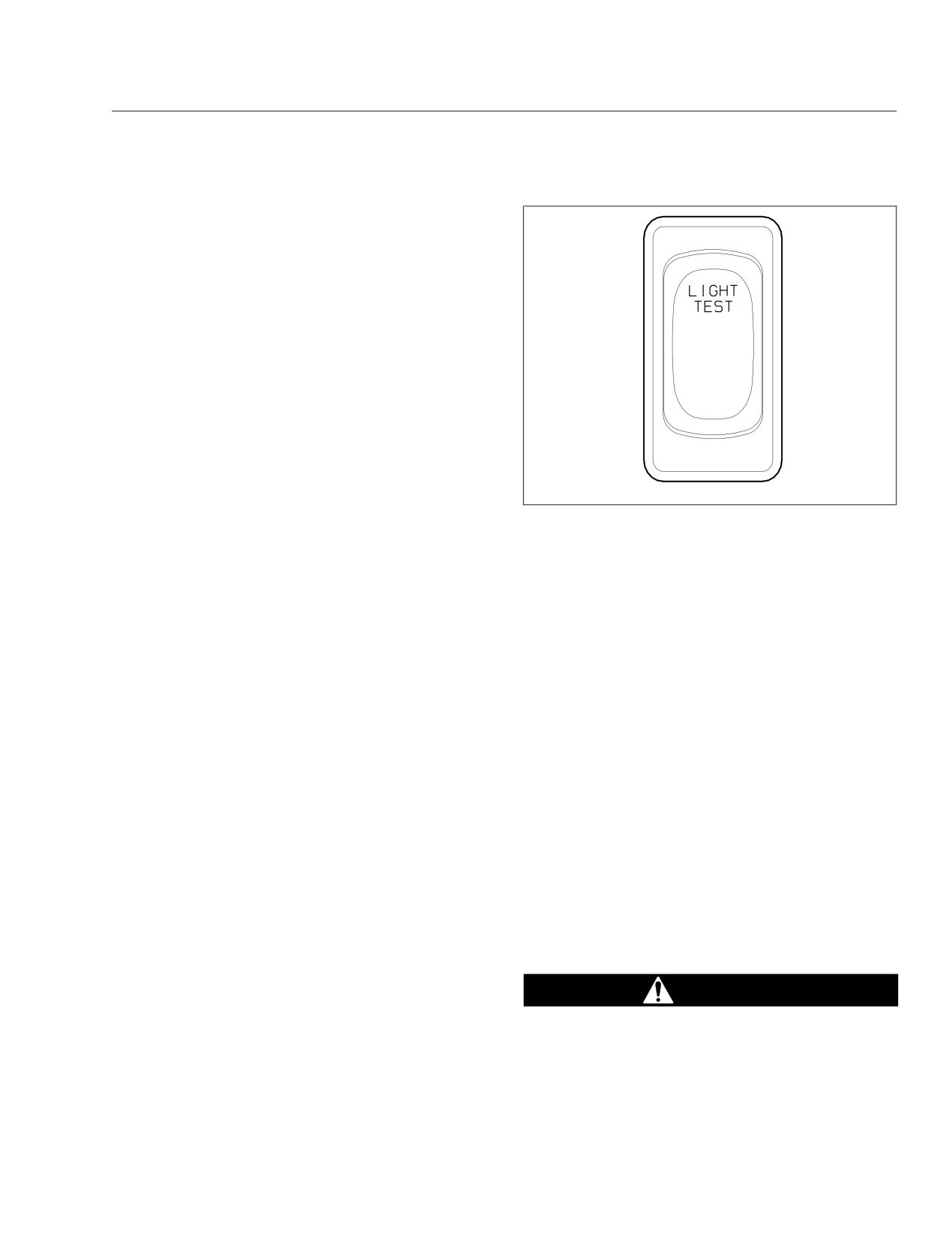
Fig.
12.7, Pretrip Light Inspection Switch
All exterior lights should be checked for proper
operation. Clean the windshield, side, and rear
•
stop arm
windows (if equipped) with a long-handled or
•
park lights (all)
telescoping window cleaning device and stan-
dard cleaning solutions.
•
turn signals
IMPORTANT: Stand only on the ground, on
•
left and right headlights (low- and
a stepladder, or an elevated walkway. The
high-beam)
vehicle entry/exit steps and handholds are
•
crossing arm (may partially retract
not designed for this purpose. The tires,
during flashing-off period)
fenders, engine, and other under-hood com-
•
taillights
ponents do not have adequate gripping sur-
faces and handholds.
•
brake lights
15.1
Turn the ignition switch to the ACCES-
•
back-up lights
SORY or ON/RUN position.
15.4
The pretrip light inspection can be stopped
15.2
Make certain the service brake is not ap-
by:
plied and the parking brake is set.
• turning the ignition switch to the
15.3
Press the pretrip inspection switch on the
OFF position;
dash, shown in Fig. 12.7, to begin the
• applying the service brake;
pretrip light inspection.
The instrument cluster will beep rapidly for
• releasing the parking brake.
five seconds, and then begin a 10-second
16.
Inspect the air brake chamber and the air brake
countdown, followed by a 2-second beep.
chamber pushrods.
The 10-second countdown period allows
the operator to exit the bus before the pre-
DANGER
trip light inspection begins. After the
2-second beep, the following exterior
Do not loosen or remove the parking brake clamp
lights will flash simultaneously:
ring for any purpose. See Fig. 12.8. The parking/
• amber warning lights (front and rear)
emergency brake section of the brake chamber is
not intended to be serviced. Serious injury or
• red warning lights (front and rear)
12.6
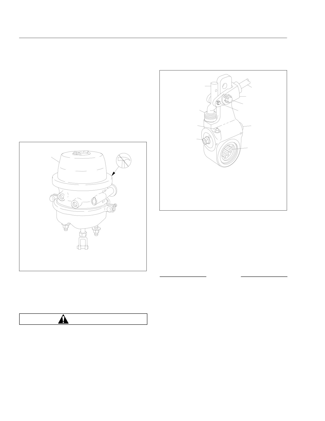
Pre- and Post-Trip Inspections and Maintenance
death may result from sudden release of the
power spring.
4
Before doing any repairs or adjustments on a
5
service/parking brake chamber, read the appli-
6
cable warnings and instructions in Group 42 of
the Saf-T-Liner C2 School Bus Workshop Manual.
7
3
8
17. Visually inspect slack adjuster components.
Inspect the slack adjuster boot for cuts or tears.
2
9
If the boot is damaged, have it replaced. See
Fig. 12.9.
1
10
1
06/17/2003
f421398
A
1.
7/16-inch Adjusting
6. Clevis
Nut
7.
1/2-inch Clevis Pin
2. Grease Fitting
8.
1/4-inch Clevis Pin
3. Boot
9.
Grease Relief
4. Link
Opening
5. Brake Chamber Piston
10. Slack Adjuster Spline
Rod
Fig. 12.9, Automatic Slack Adjuster (typical)
18.1
If a tire has been run flat or underinflated,
check for possible wheel or tire damage
before adding air.
Keep compressed air reservoirs and lines
02/22/2000
f421352
dry during tire inflation. Use well-
maintained inline moisture traps and ser-
A. Do not remove the clamp ring.
vice them regularly.
1. MGM TR-T (TR Series) Brake Chamber shown
Fig. 12.8, Parking Brake Chamber Clamp
NOTICE
18. Check tire inflation pressures.
A weekly pressure loss of 4 psi (28 kPa) or more
Tires should be checked when cool. For inflation
in a tire may indicate damage. The tire should be
pressures and maximum loads (per tire) see the
inspected and, if necessary, repaired or replaced
tire manufacturer’s guidelines.
by a qualified tire service facility.
18.2
Inflate the tires to the applicable pressures
WARNING
if needed.
IMPORTANT: The load and cold inflation
Do not operate the vehicle with underinflated or
overinflated tires. Incorrect inflation can stress
pressure must not exceed the wheel manu-
the tires and make the tires and wheels suscep-
facturer’s recommendations, even though
tible to damage, possibly leading to wheel or tire
the tire may be approved for a higher load
failure and loss of vehicle control, resulting in
inflation. Some wheels are stamped with a
serious personal injury or death.
maximum load and maximum cold inflation
rating. If they are not stamped, consult the
12.7
Pre- and Post-Trip Inspections and Maintenance
wheel manufacturer for the correct tire infla-
Otherwise a vehicle or workshop accident could
tion pressure for the vehicle load. If the load
occur, possibly resulting in serious personal in-
exceeds the maximum wheel capacity, the
jury or death.
load must be adjusted or reduced.
NOTICE
18.3
Be sure valve stem caps are on every tire
and that they are screwed on finger-tight.
Use the recommended torque values and follow
IMPORTANT: Low-rolling resistance (LRR) tires
the proper tightening sequence. Insufficient
wheel nut torque can cause wheel shimmy, re-
minimize wasted energy as a tire rolls, thereby
sulting in wheel damage, stud breakage, and ex-
decreasing rolling effort and improving fuel effi-
treme tire tread wear. Excessive wheel nut torque
ciency. If tire replacement is necessary, replace-
can break studs, damage threads, and crack
ment tires must meet or exceed the rolling resis-
discs in the stud hole area.
tance of the originally installed tires in order to
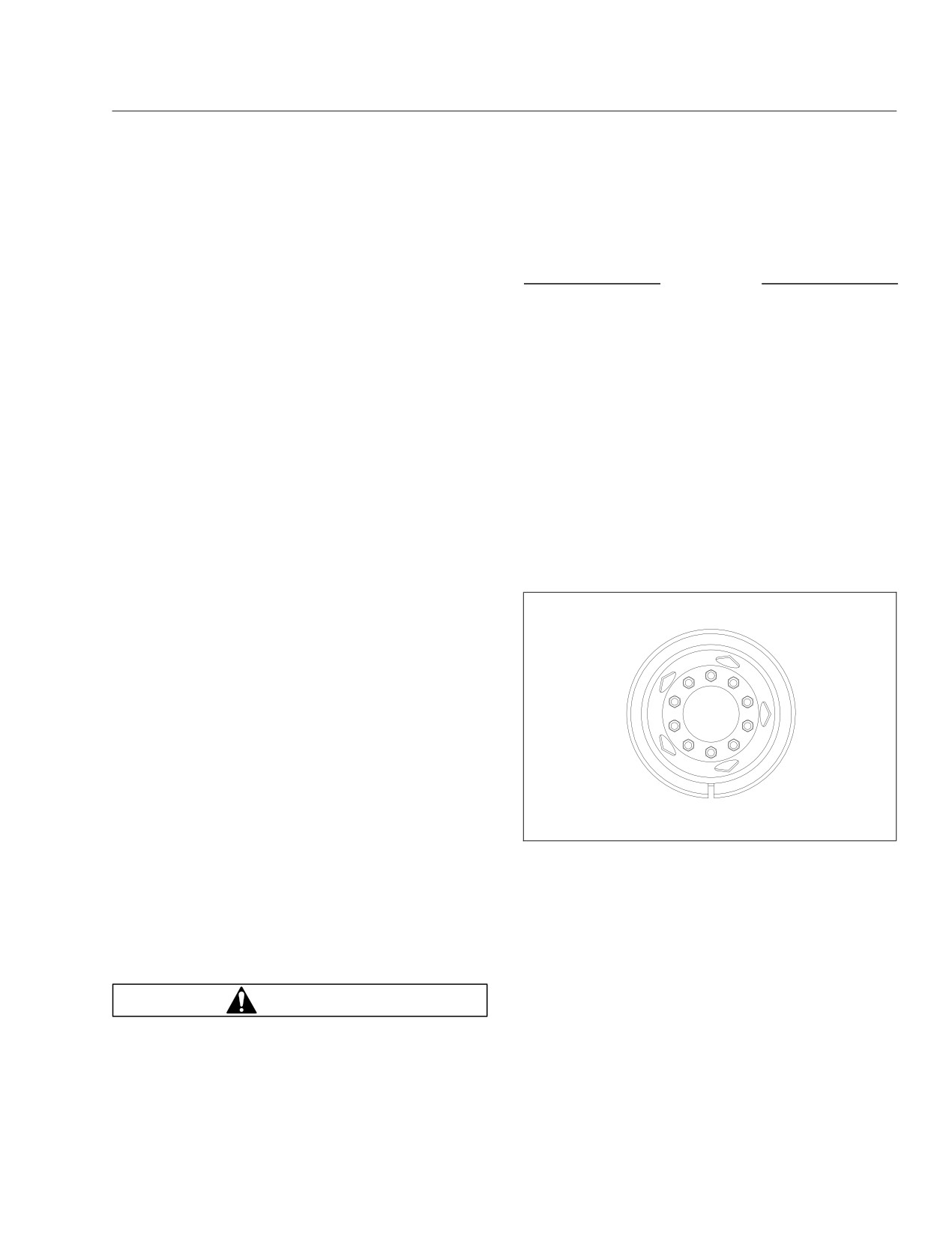
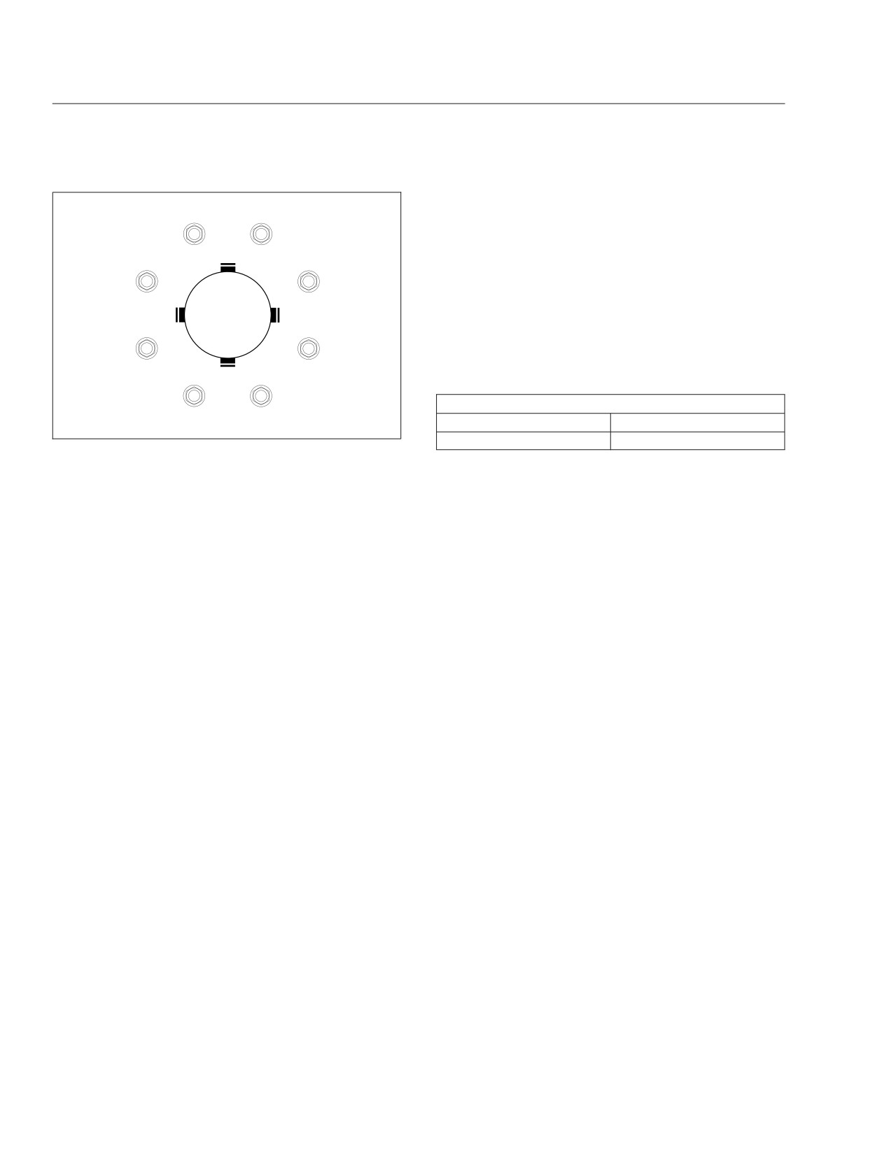
20.3
Make sure all wheel nuts are tightened. If
maintain compliance with greenhouse gas and
tightening is necessary, use the tightening
fuel efficiency regulations (GHG14).
pattern in Fig. 12.10 for 10-stud disc
Contact your tire manufacturer/supplier to deter-
wheels and Fig. 12.11 for 8-stud disc
mine the rolling resistance of the originally in-
wheels to initially tighten the flange nuts to
50 to 100 lbf·ft (68 to 136 N·m). Then
additional information and resources.
tighten the flange nuts to 450 to 500 lbf·ft
(610 to 678 N·m).
19. Inspect the condition of all tires.
19.1
Check the tire tread depth. If tread is less
1
than 4/32 inch (3 mm) on any front tire, or
10
8
less than 2/32 inch (1.5 mm) on any rear
tire, replace the tire.
19.2
Inspect each tire for bulges, cracks, cuts,
3
6
and penetrations.
19.3
Inspect each tire for oil contamination (pe-
troleum derivatives will soften the rubber
5
4
and destroy the tire).
20. Check the wheel nuts for indications of loose-
7
9
ness. Examine each wheel component.
2
08/23/93
f400081a
20.1
Remove all dirt and debris from the as-
sembly. Rust streaks or metal build-up
Fig. 12.10, Tightening Pattern, 10-Stud Disc Wheels
around stud holes, or out-of-round or worn
stud holes, may be caused by loose wheel
NOTE: Vehicles operating under severe or
nuts.
adverse conditions should be checked more
frequently.
20.2
Examine the wheel components (including
studs and nuts) for cracks or other dam-
21. Check the air brake system for proper operation.
age.
21.1
Check the air governor cut-in and cut-out
pressures. Start the engine and ensure
WARNING
the BRAKE AIR lamp goes out and the
buzzer silences when pressure reaches
Have any worn or damaged wheel components
approximately 70 psi (483 kPa) in both air
replaced by a qualified person using the wheel
reservoirs. The air governor should cut out
manufacturer’s instructions and the wheel indus-
at approximately 120 psi (827 kPa). For
try’s standard safety precautions and equipment.
vehicles with an optional dryer reservoir
12.8
Pre- and Post-Trip Inspections and Maintenance
21.4
Check the air leakage in the system.
1
2
With the parking brake applied, the trans-
mission out of gear, and the air system
fully charged, release the service brakes
7
4
and shut down the engine. Wait one min-
ute and note the air pressure drop in psi
(kPa) per minute from the primary air res-
ervoir.
If leakage exceeds the limits shown in
5
6
Table 12.2, repair all areas of leakage be-
fore driving the vehicle.
Maximum Allowable Service Brake Leakage
3
8
03/08/2012
f400052a
Brakes Released
Brakes Applied
2 psi/min. (14 kPa/min)
3 psi/min. (21 kPa/min)
Fig. 12.11, Tightening Pattern, 8-Stud Disc Wheels
Table 12.2, Maximum Allowable Service Brake
module (DRM), the cut-out pressure is
Leakage
approximately 130 psi (896 kPa).
22.
Test the parking brake on a 20 percent grade.
With the engine idling, apply the brake
pedal several times. The air governor
Apply the hand brake with the vehicle on a 20
should cut in when pressure in the primary
percent grade (or a steep grade that the vehicle
air reservoir (top air gauge) reaches ap-
may normally be parked on). If the parking brake
proximately 100 psi (690 kPa).
does not hold the vehicle, repair the parking
brake system.
21.2
Check the air pressure buildup time.
23.
Inspect the operation of the Hydro-Max® brake
With the air system fully charged, make
booster, as follows.
one full brake application and note the air
pressure reading on the primary air
23.1
With the engine off, depress the brake
gauge. Further reduce air pressure using
pedal. The warning light and buzzer
moderate brake applications, then run the
should come on, and the electric motor
engine at governed rpm. Note the time
should run.
that the pressure reaches the previously
noted reading on the primary air gauge,
23.2
Start the engine and allow the gauges to
then note the time that the air pressure
sweep. Depress the brake pedal. No
reaches cut-out pressure.
warning lights, buzzer, or electric motor
should come on.
If it takes longer than 30 seconds to reach
cut-out pressure after the primary air
24.
Inspect the engine and chassis wiring.
gauge passes the previously noted pres-
Check for loose wiring, chafed insulation, and
sure (noted after one full brake applica-
damaged or loose hold-down clamps. Tighten
tion), eliminate any leaks or replace the air
loose wires or hold-down clamps; replace dam-
compressor before operating the vehicle.
aged clamps.
21.3
Check the air pressure reserve.
Weekly Post-Trip Inspection
With the engine still off, make one full
brake application and observe the pres-
and Maintenance Procedures
sure drop on the primary air gauge. If
pressure drops more than 25 psi (172
1. Inspect the batteries and battery cables.
kPa), eliminate any leaks before operating
the vehicle.
12.9
Pre- and Post-Trip Inspections and Maintenance
WARNING
Battery posts, terminals, and related accessories
contain lead and lead compounds, chemicals
known to the State of California to cause cancer
and reproductive harm. To prevent possible per-
1
sonal injury, always wash your hands after han-
dling battery parts and related accessories.
1
1.1
Check the battery cables for chafing and
proper routing. Be sure the battery hold-
down is secure. If it is loose, tighten the
hold-down bolts; if it is damaged, replace
2
1
it. Replace the battery cable if damaged.
3
1.2
If the battery is equipped with a built-in
3
hydrometer, examine the hydrometer. If a
green dot shows in the sight glass, the
battery is sufficiently charged.
10/11/2001
f461916
If the sight glass is dark, the charge is low
and the battery must be recharged.
1.
Steering Gear Mounting Bolt
2.
Pitman Arm Pinch Bolt Nut
If the sight glass is clear, the battery has a
3.
Drag Link Nut
low level of electrolyte and must be re-
placed.
Fig. 12.12, Steering Gear Fasteners
2. Inspect the outboard side of all wheel hubs and
4.
Check the condition of the drive belts.
the hub oil seal area on the inboard side of each
Check the fan belt(s), alternator belt, and refrig-
wheel for signs of oil leakage.
erant compressor belt for signs of glazing, wear
If any oil is found on wheel and tire or brake
(frayed edges), damage (breaks or cracks), or oil
components, remove the vehicle from service
contamination. If a belt is glazed, worn, dam-
until the leak has been fixed.
aged, or oil soaked, replace it.
If needed, fill the hubs to the level indicated on
5.
After resetting the air intake restriction indicator
the hub cap.
during the daily pretrip inspection, check the indi-
cator again with the engine off.
IMPORTANT: Before removing the fill plug, al-
ways clean the hub cap and plug.
5.1
Check an indicator with graduations to see
if air restriction exceeds 25 inH2O.
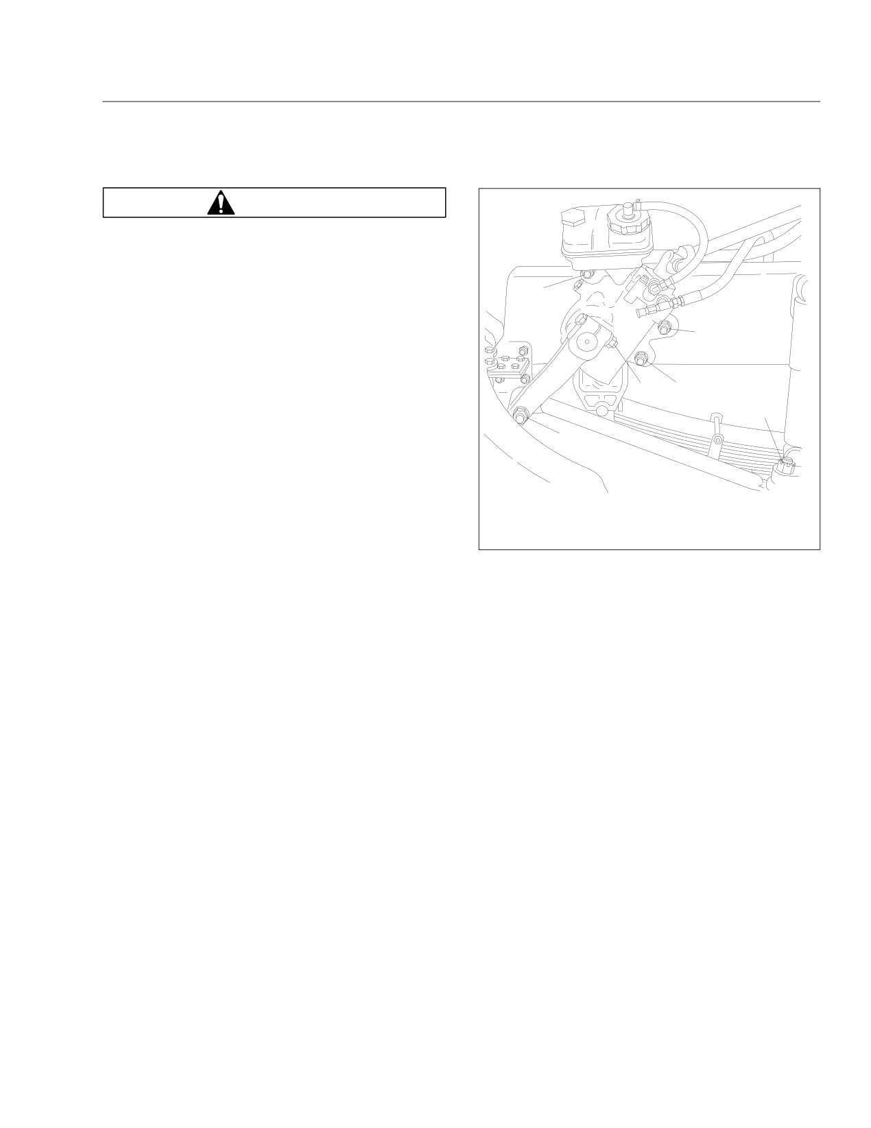
3. Inspect the steering components.
Check a go/no-go indicator without gradu-
3.1
Inspect tie rods, steering arms, and the
ations to see if the colored bar shows
drag link for signs of looseness (i.e., shiny
through the clear window.
spots or rust tracks). See Fig. 12.12.
5.2
If air restriction exceeds the maximum al-
3.2
Check the steering gear mounting bolts
lowable value, operate the vehicle for one
and pitman arm nut, if equipped, for signs
more day, making sure not to run the en-
of looseness.
gine over rated rpm. Refer to the engine
3.3
Check the drag link nuts for missing cotter
operation manual for more information on
pins.
rated rpm for your engine.
3.4
Inspect the steering intermediate shaft and
end yokes for excessive looseness or
other damage.
12.10
Pre- and Post-Trip Inspections and Maintenance
5.3
If air restriction exceeds the maximum
A
value again, replace the air cleaner. For
instructions, refer to Group 09 of the Saf-
T-Liner C2 School Bus Maintenance
Manual.
Monthly Post-Trip Inspection
and Maintenance Procedures
WARNING
B
Battery posts, terminals, and related accessories
contain lead and lead compounds, chemicals
known to the State of California to cause cancer
and reproductive harm. To prevent possible per-
sonal injury, always wash your hands after han-
04/26/2012
f460513a
dling battery parts and related accessories.
A. Open caps and check fluid level.
B. Fill to this level.
1. Clean the batteries.
1.1
Remove any corrosion from the hold-down
Fig. 12.13, Check the Hydraulic Brake Fluid Level
(typical)
and the top of the battery.
3.2
Align a reference mark on the steering
NOTICE
wheel to a ruler, then slowly turn the
steering wheel in the opposite direction
Take care to keep the vent plugs tight so that the
until motion is again detected at the
neutralizing solution does not enter any of the
wheels. See Fig. 12.14.
battery cells and damage the battery.
1.2
Use a soda solution to neutralize the acid
present, then rinse off the soda solution
with clean water.
1.3
If the battery posts or cable terminals are
corroded, disconnect the terminals from
the posts. Clean them with a soda solution
A
and a wire brush. After cleaning, connect
the terminals to the battery posts, then
apply a thin coat of petroleum jelly to the
posts and terminals to help retard corro-
sion.
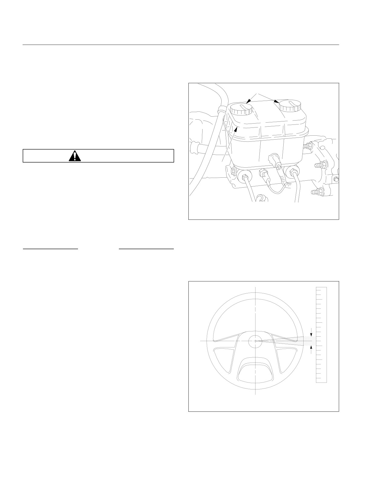
2. Check the fluid level in the hydraulic clutch reser-
voir, if equipped.
If necessary, add DOT 3 brake fluid. See
Fig. 12.13.
10/10/95
f461057
3. Check the steering wheel for excessive play.
A. Lash Area
3.1
Start the engine. With the front tires
Fig. 12.14, Measuring Lash at the Steering Wheel
straight ahead, turn the steering wheel
until motion is observed at the front
wheels.
12.11
Pre- and Post-Trip Inspections and Maintenance
3.3
Measure the lash (free play) at the rim of
the steering wheel. Excessive lash exists
if steering wheel movement exceeds 2-1/2
inches (64 mm) with a 20-inch (508-mm)
steering wheel, or 2-1/4 inches (57 mm)
with an 18-inch (457-mm) steering wheel.
3.4
If there is excessive lash, check the steer-
ing system for wear or incorrect adjust-
ment before operating the vehicle.
4.
Check the brake lining wear on vehicles
equipped with air brakes.
Proper brake operation is dependent on periodic
maintenance and inspection of the brake linings.
4.1
Apply the parking brakes, and chock the
tires to prevent vehicle movement.
02/24/2010
f750039
4.2
If the axle assembly is not equipped with
Fig. 12.15, Body Mounting Bolts and Clip (number and
a dust shield or backing plate, measure
location vary)
the axle brake lining thickness. If any of
the brake linings are worn to less than
pressure washer to clean these areas, use the
3/16 inch (4.8 mm) at the thinnest point,
lowest possible pressure setting.
replace the linings on all brake assemblies
6.
Clean the undercarriage of the bus.
on that axle.
Salt and de-icing material used on road surfaces
4.3
If the axle assembly is equipped with a
in winter months deteriorates the metal of the
dust shield or backing plate, remove the
vehicle. Use a high-pressure washer at the low-
inspection plugs to inspect the brake lining
est setting to clean the undercarriage of the bus.
thickness. If any of the brake linings are
If corrosion or separation of the undercoat to
worn to less than approximately 3/16 inch
body floor is visible, apply additional undercoat-
(4.8 mm) at the thinnest point, replace the
ing.
linings on all brake assemblies on that
axle.
4.4
Install the inspection plugs in the dust
shields or backing plates, if so equipped.
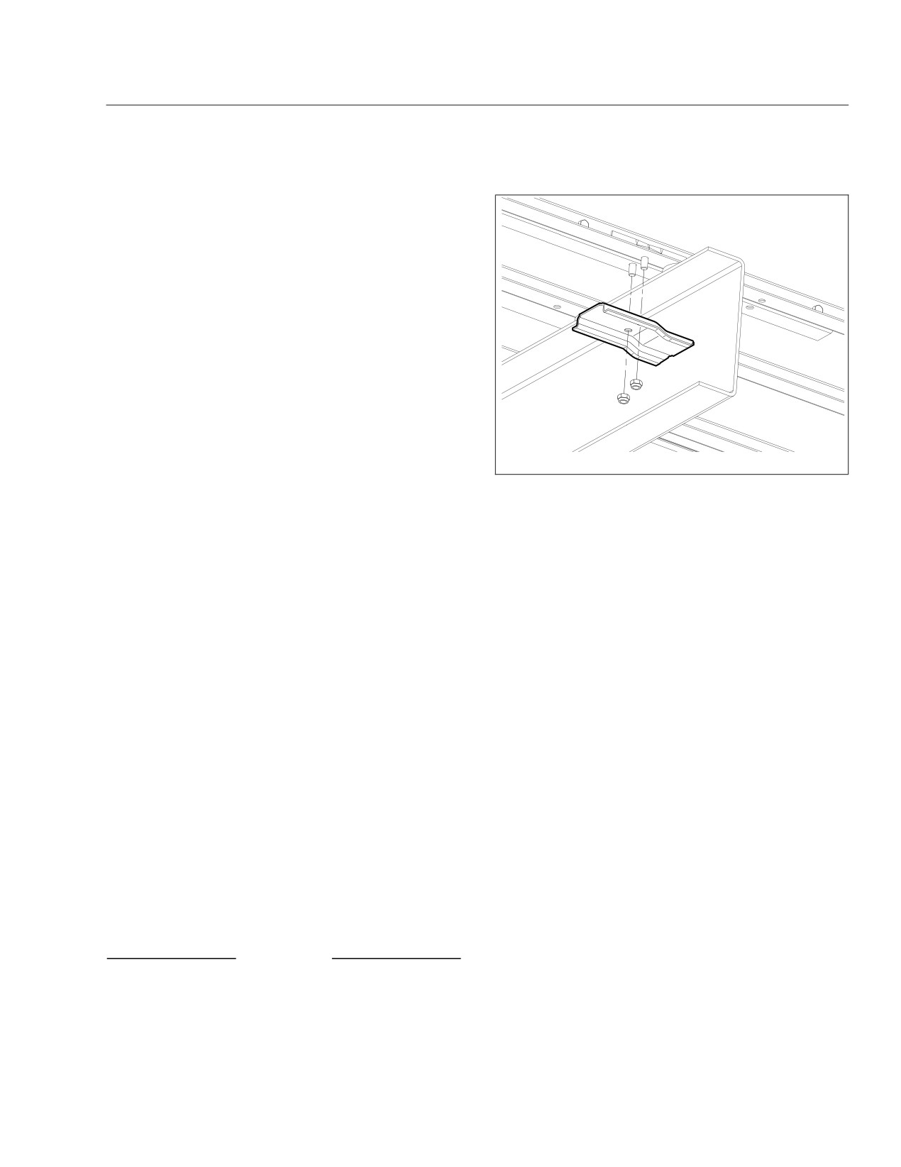
NOTE: The number and location of body mount-
ing bolts and clips vary, depending on the op-
tions and wheelbase of each vehicle.
5. Check that the body mounting bolts and clips are
securely fastened.
If needed, tighten the bolts 30 lbf·ft (41 N·m).
Figure 12.15 shows an example of body mount-
ing bolts and a clip.
NOTICE
When cleaning areas containing electrical com-
ponents and connections, take care to protect
these items from water intrusion. When using a
12.12

13
Cleaning and Care
Washing and Polishing
13.1
Care of Fiberglass Parts
13.1
Care of Chrome Parts
13.1
Dashboard and Instrument Panel Care
13.1
Vinyl Upholstery Cleaning
13.1
Floor Cleaning
13.2

Cleaning and Care
Washing and Polishing
Care of Chrome Parts
To protect the new vehicle’s finish, follow these
To prevent rust, keep chrome parts clean and pro-
guidelines carefully:
tected at all times. This is especially important during
winter driving and in coastal areas where there is
• During the first 30 days, rinse the vehicle fre-
exposure to salt air.
quently with water. If the vehicle is dirty, use a
mild liquid soap. Do not use detergent.
When cleaning chrome parts, use clean water and a
soft cloth or sponge. A mild detergent may also be
• During the first 30 days, do not use anything
used.
abrasive on the vehicle. Brushes, chemicals,
and cleaners may scratch the finish.
Sponge gently, then rinse. If necessary, use a non-
abrasive chrome cleaner to remove stubborn rust or
• During the first 120 days, do not wax the
other material. Do not use steel wool.
vehicle.
To help protect the chrome after cleaning, apply a
To extend the life of the vehicle’s finish, follow these
coat of polishing wax to the surface. Never use wax
guidelines:
on parts that are exposed to high heat, such as ex-
• Avoid washing the vehicle in the hot sun. Al-
haust pipes.
ways use water. After the vehicle is completely
washed, dry it with a towel or chamois.
Dashboard and Instrument
• Do not dust painted surfaces with a dry cloth,
Panel Care
as this will scratch the paint.
• Do not remove ice or snow from a painted sur-
NOTICE
face with a scraper of any sort.
When cleaning the dashboard, instrument panel,
• To prevent damage to the finish, wax it regu-
or gauge lens covers, do not use Armor-All Pro-
larly. If the finish has become dull, remove oxi-
tectant®, STP Son-of-a-Gun®, window cleaner, or
dized paint using a cleaner specifically de-
other equivalent treatments. These cleaners con-
signed for this purpose before waxing. Remove
tain vinyl plasticizers which can cause stress
all road tar and tree sap before waxing.
crazing in the interior plastic panels and can re-
Freightliner recommends the use of a high
sult in cracking of the panels. Some cleaners can
quality brand of cleaner or cleaner-polish and
also have an adverse effect on the clear plastic
polishing wax be used.
of instrument panels and gauge lens covers, re-
• Do not let diesel fuel or antifreeze stand on a
sulting in a foggy or cloudy appearance. This
painted surface. If either should occur, rinse
type of damage is not covered by vehicle war-
the surface off with water.
ranty.
• To prevent corrosion, have any nicks or other
To clean the dashboard, instrument panel, and gauge
damage on the finish touched up as soon as
lens covers, use a cloth dampened with warm soapy
possible.
water. Make certain to wring the cloth out well before
cleaning, as excess water will damage the electrical
• Park the vehicle in a sheltered area whenever
components.
possible.
Vinyl Upholstery Cleaning
Care of Fiberglass Parts
To prevent soiling, frequent vacuuming or light brush-
Wash unpainted fiberglass air fairings and shields
ing to remove dust and dirt is recommended. Harsh
monthly with a mild detergent, such as dishwashing
cleaning agents can cause permanent damage to
liquid. Avoid strong alkaline cleansers.
vinyl upholstery. To preserve the upholstery and pre-
Apply a wax specifically designed for fiberglass.
vent damage, carefully review the following sections
for recommended cleaning procedures. Waxing or
refinishing improves soil resistance and cleanability
13.1

Cleaning and Care
for all vinyls. Any hard wax, such as that used on
tion to prevent the solution from seeping into the
automobiles, may be used.
seams or it will weaken the cotton thread.
Ordinary Dirt
Nail Polish and Nail Polish Remover
Wash the upholstery with warm water and mild soap,
Prolonged contact with these substances causes per-
such as saddle or oil soap. Apply soapy water to a
manent damage to vinyl. Careful blotting immediately
large area and allow to soak for a few minutes, then
after contact minimizes damage. Do not spread the
rub briskly with a cloth to remove the dirt. This can
liquid during removal.
be repeated several times as necessary.
Shoe Polish
If dirt is deeply imbedded, use a soft bristle brush
after applying the soap.
Most shoe polishes contain dyes which penetrate
If dirt is extremely difficult to remove, wall-washing
vinyl and stain it permanently. Shoe polish should be
preparations normally found around the home can be
wiped off as quickly as possible using naphtha or
used. Powdered cleaners, such as those used for
lighter fluid. If staining occurs, try the procedure used
sinks and tiles, are abrasive and must be used with
for sulfide stains.
caution as they can scratch the vinyl or give it a per-
manent dull appearance.
Ball Point Ink
Ball point ink can sometimes be removed if rubbed
Chewing Gum
immediately with a cloth dampened with water or
Harden the gum with an ice cube wrapped in a plas-
rubbing alcohol. If this does not work, try the proce-
tic bag, then scrape it off with a dull knife. Any re-
dure used for sulfide stains.
maining traces of gum can be removed with an all-
purpose light oil (peanut butter will also work) and
Miscellaneous
wiped off.
If stains do not respond to any of the treatments de-
scribed above, it is sometimes helpful to expose the
Tars, Asphalts, and Creosote
vinyl to direct sunlight for up to 30 hours. Mustard,
Tars, asphalts, and creosote stain vinyl after pro-
ball point ink, certain shoe polishes, and dyes often
longed contact. They should be wiped off immedi-
bleach out in direct sunlight, leaving the vinyl undam-
ately and the area carefully cleaned, using a cloth
aged.
dampened with naphtha.
Floor Cleaning
Paint and Shoe Heel Marks
Dirt and other abrasive material that accumulates on
Paint should be removed immediately. Do not use
the floor will shorten the life of the floor covering.
paint remover or liquid-type brush cleaner on vinyl.
Daily sweeping and cleaning should be performed to
An unprinted cloth, dampened with naphtha or tur-
maintain the floor covering. Do not use any floor
pentine may be used. Use care to prevent contact
sweeping cleaner or solvent, as they may cause the
with parts of the upholstery that are not vinyl.
floor covering to separate and lift from the floor.
Begin at the front of the vehicle and sweep toward
Sulfide Stains
the rear and side emergency door(s). This will en-
sure a check of the emergency door’s operation, as
Sulfide compounds, such as those found in eggs and
well as the removal of items that could keep the
some canned goods, can stain after prolonged con-
emergency door from sealing properly.
tact with vinyl. These stains can be removed by plac-
ing a clean, unprinted piece of cloth over the spotted
Oil and grease deteriorate the floor covering quickly
area and pouring a liberal amount of 6 percent hy-
and should be removed as soon as possible. Do not
drogen peroxide onto the cloth. Allow the saturated
use harsh detergents or excessive amounts of water
cloth to remain on the spot for 30 to 60 minutes. For
to remove these items. Instead, mop with a mild
stubborn spots, allow the hydrogen-peroxide satu-
soap solution and remove any excess water.
rated cloth to remain on the area overnight. Use cau-
13.2

Cleaning and Care
To maintain the floor covering appearance, occasion-
ally wax it with a non-skid floor wax.
Over time, the floor covering may appear dull. If this
should occur, mop the floor with a 10% bleach to
90% water solution.
13.3

14
In an Emergency
Hazard Warning Lights
14.1
Fire Extinguisher
14.1
Emergency Kit
14.1
Emergency Starting With Jumper Cables
14.1
Towing
14.3
Emergency Exits
14.4
Running Out of Fuel
14.5
Changing a Flat Tire
14.6
In an Emergency
Hazard Warning Lights
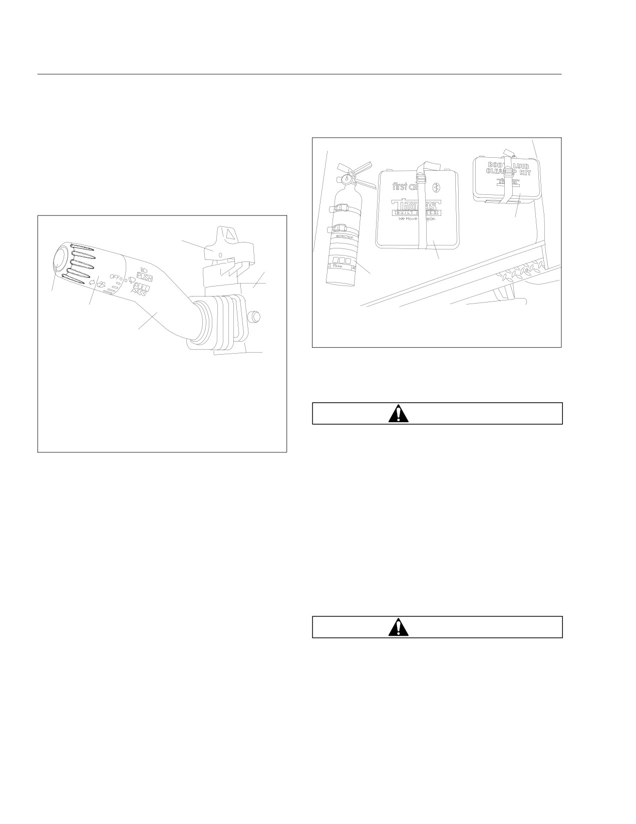
The hazard warning light switch is part of the multi-
function turn signal switch. It is a red rocker switch
located on the top of the multifunction switch module.
See Fig. 14.1.
3
4
5
2
1
1
12/10/2003
f580375
2
1. Fire Extinguisher
2. First Aid Kit
3
3. Body Fluid Cleanup Kit
Fig. 14.2, Emergency Equipment
11/16/2001
f820386
Press down on the upper part of the rocker to activate
the flares and reflector along the side of the road to
the hazard warning lights.
alert other drivers that an emergency situation exists.
1. Washer Button
2. Wiper Control Dial
WARNING
3. Turn Signal Lever
4. Hazard Warning Light Switch (red)
Use extreme care when placing flares in emer-
5. Multifunction Switch Module
gency situations that involve exposure to flam-
Fig. 14.1, Multifunction Turn Signal Switch
mable substances such as fuel. An explosion or
fire could occur causing serious personal injury.
To activate the hazard warning lights, press down on
the upper part of the rocker switch (towards the
Emergency Starting With
dash). To cancel the hazard warning lights, press
down on the lower part of the rocker switch (towards
Jumper Cables
the steering wheel).
NOTE: Jumpstarting vehicles equipped with the
Eaton® Hybrid System is identical to non-hybrid
Fire Extinguisher
vehicles, which use the vehicle 12-volt battery
A fire extinguisher is located on the floor, to the right
system.
of the driver’s area at the front of the bus. See
When using jumper cables, follow the instructions
Fig. 14.2.
below.
Emergency Kit
WARNING
An optional emergency kit is located to the right of
Batteries release explosive gas. Do not smoke
the driver’s area at the front of the bus or in a com-
when working around batteries. Put out all flames
partment over the driver’s seat. The kit includes one
and remove all sources of sparks or intense heat
or more of the following: a first aid kit, a reflective
in the vicinity of the battery. Do not allow the ve-
vest, a triangular reflector, and a flare kit. See
hicles to touch each other. Do not lean over the
Fig. 14.2.
batteries when making connections, and keep all
If there is an emergency while driving, cautiously pull
other persons away from the batteries. Failure to
off the road. Turn on the hazard warning lights. Place
follow these precautions could lead to severe
14.1
In an Emergency
personal injury as a result of an explosion or
4. Connect the other end of the positive jumper
acid burns.
cable to the positive terminal on the booster bat-
tery providing the charge.
NOTICE
WARNING
Make sure that both starting systems are the
same voltage. Electronic devices on both ve-
Do the next step exactly as instructed and do not
hicles can be damaged when connected to a ve-
allow the clamps of one cable to touch the
hicle with a different operating voltage.
clamps of the other cable. Otherwise, a spark
could occur near a battery, possibly resulting in
1. Apply the parking brakes and turn off all lights
severe personal injury from explosion or acid
and other electrical devices.
burns.
IMPORTANT: Do not attempt to jump start a
5. Connect the negative (-) jumper cable to the
damaged battery.
negative terminal on the booster battery.
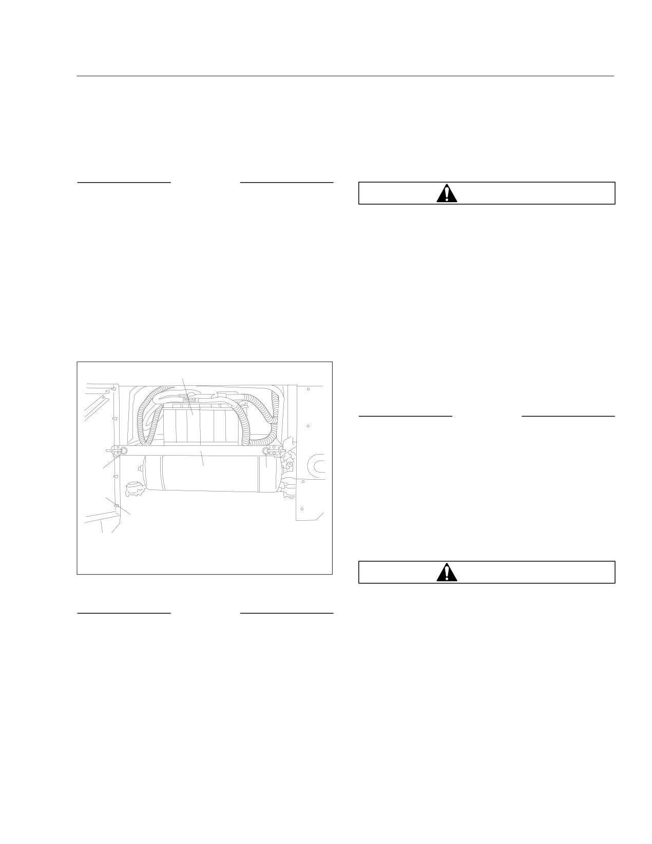
2. Open the battery door to access the batteries.
6. Connect the other end of the negative jumper
Pull both pull-pin spring latches and slide the
cable to the negative ground stud on the vehicle
battery tray out. See Fig. 14.3.
requiring the jump start.
7. Start the engine of the vehicle providing the jump
4
start and let the engine run for a few minutes to
charge the batteries of the other vehicle.
NOTICE
Do not crank the engine for more than 30 sec-
onds at a time during any of the following proce-
dures. Wait two minutes after each try to allow
2
3
2
the starter to cool. Failure to do so could cause
starter damage.
8. Attempt to start the engine of the vehicle with the
1
batteries receiving the charge.
9. When the engine starts, let it idle for a few min-
12/05/2003
f544365
utes.
1. Battery Access Door
3. Battery Tray
2. Pull-Pin Spring Latch
4. Battery
WARNING
Fig. 14.3, Battery Access
Do the next step exactly as instructed and do not
allow the clamps of one cable to touch the
NOTICE
clamps of the other cable. Otherwise, a spark
could occur near a battery, possibly resulting in
Always connect the batteries and jumper cables
severe personal injury from explosion or acid
correctly (positive-to-positive and negative-to-
burns.
negative). Connecting a charging device back-
wards (positive-to-negative) can severely damage
10. Disconnect the negative jumper cable from the
the vehicle electrical content and cause non-
negative cable stud on the jump started vehicle.
warrantable failures.
11. Disconnect the negative jumper cable from the
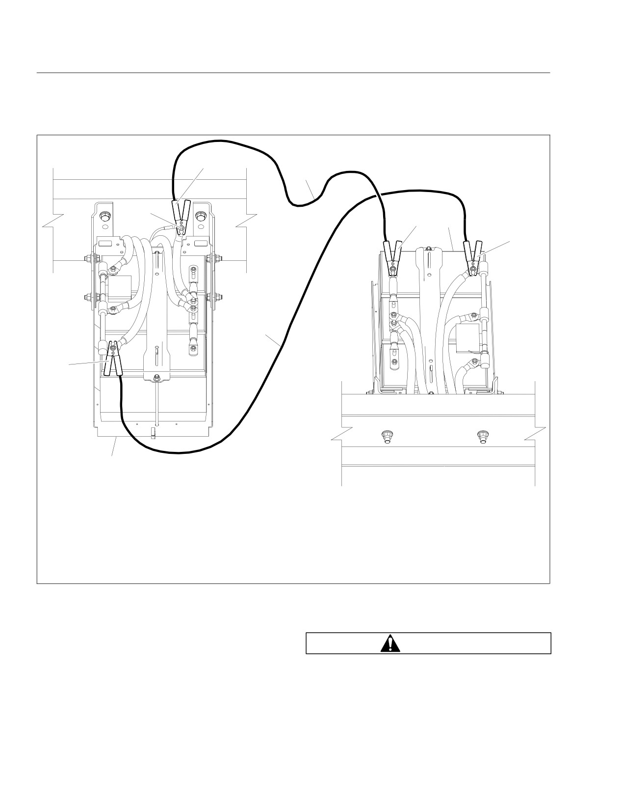
3. Connect the positive (+) jumper cable to the
booster battery.
positive terminal on the discharged battery. See
12. Disconnect the positive cable from the booster
Fig. 14.4.
battery.
14.2
In an Emergency
4
D
B
3
E
2
−
−
−
−
C
−
1
−
A
01/07/2011
f545725
Disconnect jumper cables in the REVERSE order that they were connected.
A. Discharged Battery
C. Positive Jumper Cable
E. Booster Battery
B. Negative Ground Stud
D. Negative Jumper Cable
1.
1st Connection: Positive Jumper Cable to Discharged Battery
2.
2nd Connection: Positive Jumper Cable to Booster Battery
3.
3rd Connection: Negative Jumper Cable to Booster Battery
4.
4th Connection: Negative Jumper Cable to Negative Ground Stud (discharged battery)
Fig. 14.4, Jumper Connections (three battery system shown for clarity)
13. Disconnect the other end of the positive jumper
Towing
cable from the jump started vehicle.
14. Pull both pull-pin spring latches and slide the
WARNING
battery tray back into position. Release the pull-
pin spring latches to lock the battery tray, then
Do not tow an unbraked vehicle if the combined
close the battery door.
weight of both vehicles is more than the sum of
14.3

In an Emergency
the gross axle weight ratings (GAWR) of the tow-
5. Attach the towing device. Due to the many vari-
ing vehicle. Otherwise brake capacity will be in-
ables that exist in towing, positioning the lifting
adequate, which could result in personal injury or
and towing device is the sole responsibility of the
death.
towing-vehicle operator.
IMPORTANT: When it is necessary to tow the
6. Lift the vehicle and secure the safety chains. If
vehicle, make sure the instructions below are
extra towing clearance is needed, remove the
closely followed to prevent damage to the ve-
front wheels.
hicle.
7. Connect the clearance lights, taillights, and sig-
nal lights. Connect any special towing lights re-
NOTICE
quired by local regulations.
When towing or pushing the vehicle, regardless
WARNING
of the distance or speed traveled, either discon-
nect the driveshaft at the rear axle and support it
Failure to chock the tires or connect the tow
as necessary, or remove the axle shafts. Failure
truck’s air brake system before releasing the
to do this when towing the vehicle with the rear
spring parking brakes could allow the disabled
wheels on the ground could result in damage to
vehicle to suddenly roll. This could cause prop-
the transmission and other parts.
erty damage or personal injury.
NOTE: Towing rules and regulations vary from
8. Chock the tires on the disabled vehicle and con-
federal, state, local, and transit authority. These
nect the towing vehicle’s air brake system to the
laws must be followed when towing the bus.
vehicle being towed. Then, release the spring
parking brake and remove the chocks.
Front Towing Hookup
Emergency Exits
NOTICE
Emergency Door
The vehicle should never be towed from the rear.
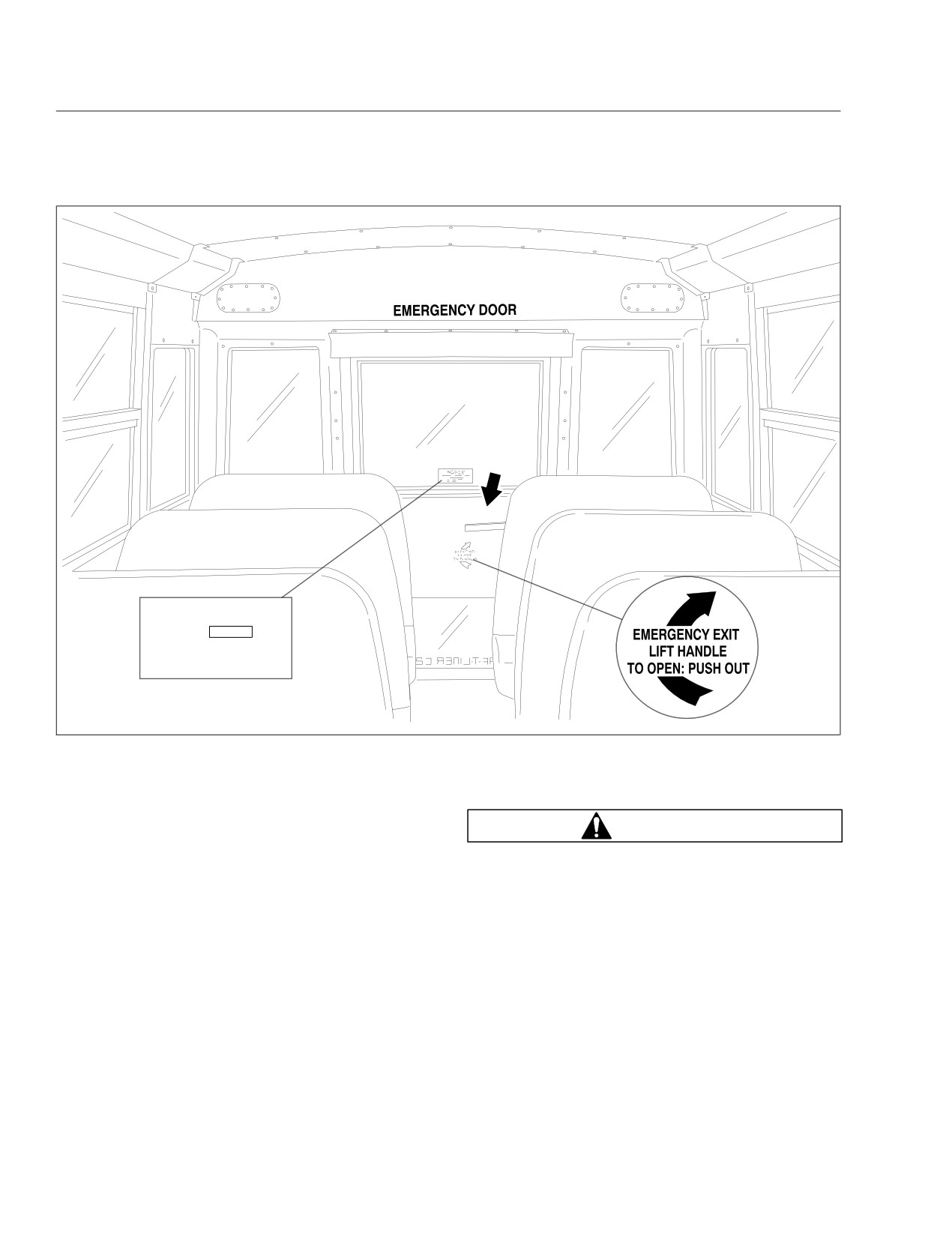
An emergency exit door is located at the rear of the
The gross axle weight rating (GAWR) of the front
bus. The emergency door has a locking capability in
axle may not be sufficient to support the in-
the open position to allow a clear exit from the bus.
creased load when towing from the rear. This
The release handle for the emergency exit door is
could damage the front axle.
protected to prevent accidental opening. Instructions
for opening the emergency exit door are clearly dis-
1. Disconnect the battery ground cables.
played on the door face. See Fig. 14.5.
2. Remove both drive axle shafts.
A warning buzzer in the bus activates when the re-
3. Cover the ends of the hubs with metal plates or
lease handle is not in the locked position.
plywood cut to fit the axle opening, and drilled to
IMPORTANT: The vehicle should not be driven if
fit the axle shaft studs. This prevents lubricant
from leaking out and will keep contaminants from
an emergency exit buzzer is sounding.
getting into and damaging the wheel bearings
and axle lubricant.
Using the Main Entry/Exit Door in an
Emergency
NOTICE
In an emergency, it may be necessary to use the red
switch above the main door to open the door. Push
Failure to protect the frame rails from the chains
down on the red switch to open the door, then push
could cause damage, leading to eventual frame
the door open. See Fig. 14.6 and Fig. 14.7.
failure.
4. Remove the bumper.
14.4
In an Emergency
NOTICE
TO RELEASE
OPENED
DOOR
FROM HELD POSTIION
− OPEN DOOR FULLY
− CLOSE DOOR
08/26/2008
f602145
Fig. 14.5, Emergency Door
Emergency Roof Escape Hatches
Running Out of Fuel
The bus may contain emergency roof escape
hatches located near the front and rear of the bus,
WARNING
according to Federal or State regulations. On buses
equipped with an emergency roof escape hatch, the
Do not mix gasoline or alcohol with diesel fuel.
opening instructions are clearly displayed on the
This mixture could cause an explosion. When fill-
hatch cover. See Fig. 14.8.
ing fuel tanks, do not smoke or use an open
flame near the fuel tanks. Combustion of diesel
Emergency Window Exits
fuel oil or fuel vapors could result, possibly caus-
ing personal injury or property damage.
The bus has windows designated as emergency
1. If possible, stop the vehicle on a level surface,
exits. To open the windows in emergency situations,
away from traffic.
follow the instructions that are clearly displayed on
the window frame.
2. Apply the parking brake.
NOTE: Some states require that the operating
IMPORTANT: Any time the vehicle runs out of
instructions be located on the window glass.
fuel, the fuel system should be primed. This will
14.5
In an Emergency
3
2
1
01/10/2007
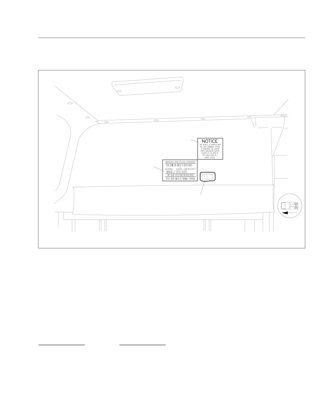
f544925
1. Emergency Switch for Main Entry Door
3. Child Reminder Notice
2. Main Entry Door Emergency Release Operations Decal
Fig. 14.6, Emergency Switch for Main Entry Door
purge any trapped air in the system and allow
starter to cool. Failure to do so could cause
fuel to fill the fuel filter.
starter damage.
3. Prime the engine. See the engine manufacturer’s
5. After adding fuel to the fuel tank, start the en-
manual for instructions to prime the fuel system.
gine. Once the vehicle is running, let the engine
If further assistance is needed, call the Freight-
idle until it operates smoothly before driving the
liner Customer Assistance Center at 1-800-385-
vehicle.
4357 or 1-800-FTL-HELP.
Changing a Flat Tire
4. Add fuel to the fuel tank.
IMPORTANT: If a flat tire occurs while driving,
If the vehicle is equipped with a propane engine,
add at least 9 to 10 gallons (34 to 38 L) of liquid
gradually decrease vehicle speed. Holding the
propane.
steering wheel firmly, move to a safe place on
the side of the road.
NOTICE
1. Stop the vehicle on a level surface, away from
traffic.
Do not crank the engine for more than 30 sec-
onds at a time during the following procedure.
2. Apply the parking brake, place the transmission
Wait two minutes after each try to allow the
in neutral (N), and shut down the engine.
14.6
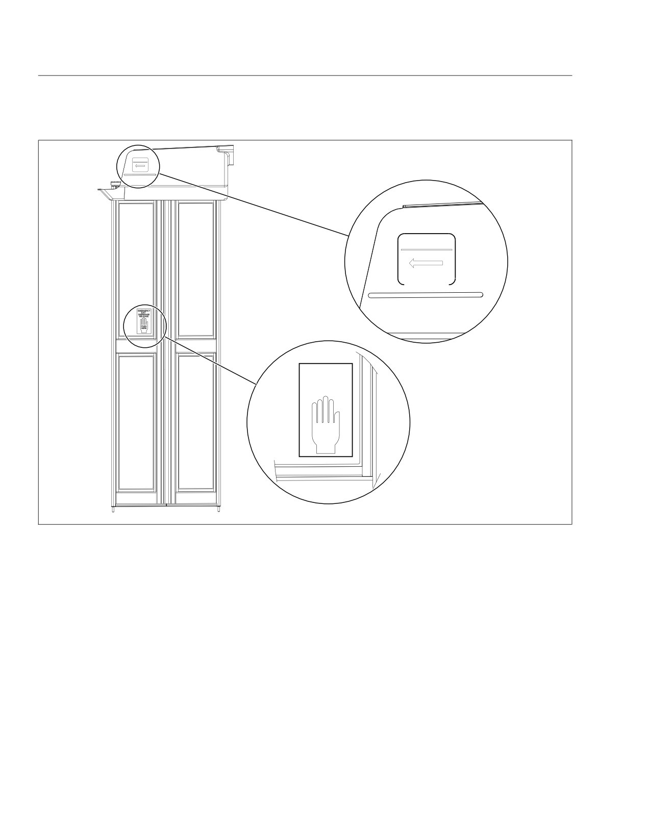
In an Emergency
EMERGENCYRELEASE
DISENGAGE
RELEASE
P
SH
EMERGENCYRELEASE
DISENGAGE
RELEASE
PUSH FORWARD DOOR
TO RESET DOORS, DRIVER’S DOOR CONTROLS MUST BE IN
THE ’OPEN’ POSITION BEFORE RE−ENGAGING RELEASE
EMERGENCY
EXIT
DISENGAGE
RELEASE
PUSH
HERE
05/09/2007
f080145
Fig. 14.7, Disengaging the Main Entry Door in an Emergency
3. Turn on the hazard warning lights.
centered and within the bottom surface of the
bumper support as shown in Fig. 14.9. Do not
4. Block the wheel diagonally opposite the wheel
position the jack under the dropped frame rails
being changed.
in the center section of the bus.
5. Remove the spare wheel, jack, jack handle, and
lug wrench from storage.
6. Place the jack on a solid surface. Insert the jack
handle and pump the handle slightly. Do not
IMPORTANT: The jacking point for the front
raise the wheel off of the ground yet. Loosen the
wheels is on the front axle beam and other loca-
wheel lug nuts, but do not remove them.
tions shown in Fig. 14.9. The jacking point for
IMPORTANT: The dual rear wheels are attached
rear wheels is on the rear axle and at the loca-
using two-element lug nuts. The larger nut re-
tions on the rear suspension H-frame, shown in
tains the outer dual. The inner square stud re-
Fig. 14.9.
tains the inner dual. Remove and install these
Only use the front bumper locations if the bus is
nuts separately. The rear dual outer lug nut
equipped with a jackable bumper. When jacking
must be loosened to check and retighten the
the front bumper, the jacking point(s) must be
inner nut.
14.7
In an Emergency
snug. See Group 40 of the Saf-T-Liner C2
School Bus Workshop Manual for wheel tighten-
ing patterns and torque specifications. Lower the
vehicle until the wheel touches the ground.
Tighten the nuts.
10. Finish lowering the vehicle to the ground, then
remove the jack.
11. Remove the block, then stow the jack, jack
handle, and lug wrench.
12. After operating the vehicle for 50 to 100 miles
(80 to 161 km), retighten the wheel nuts to the
specified torque values.
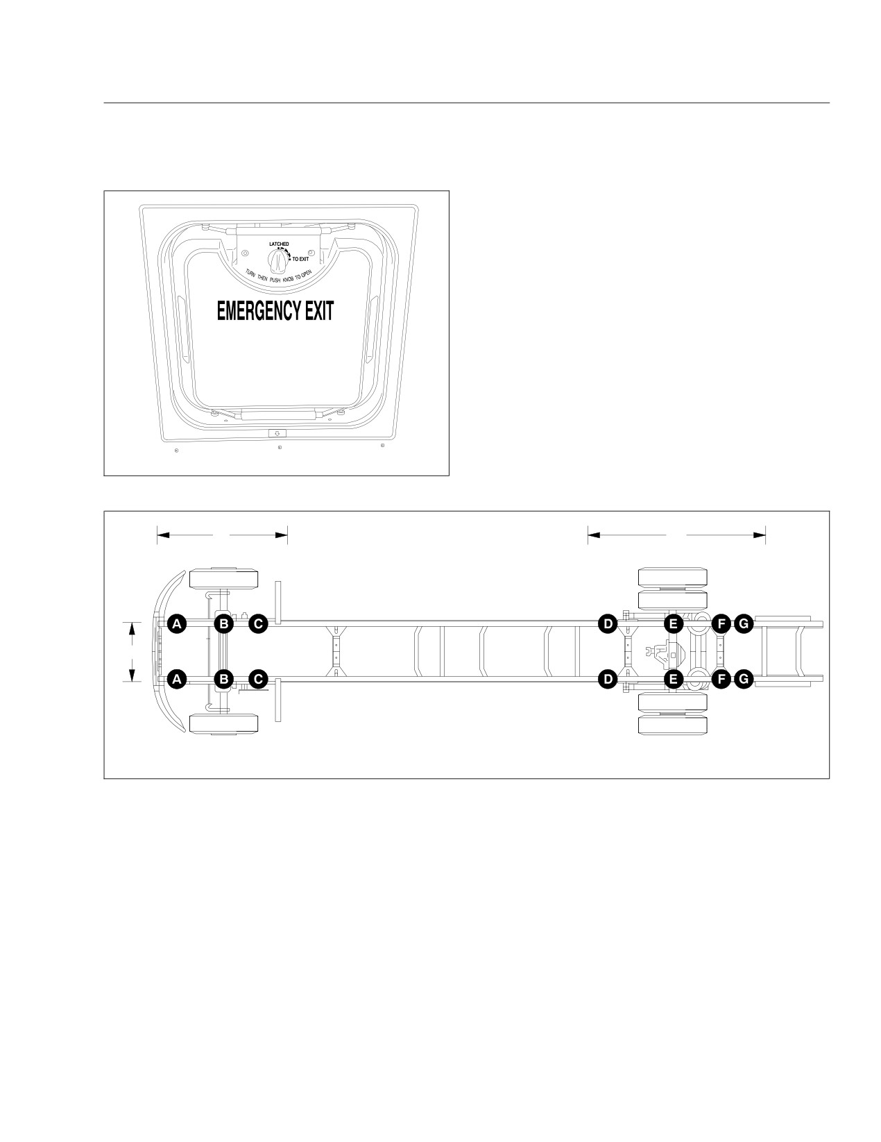
12/05/2003
f602155
Fig. 14.8, Emergency Roof Escape Hatch
1
2
3
12/13/2010
f311093
1. Jack Locations—Front Axle
2. Jack Locations—Rear Axle
3. Jack Locations—Front Bumper
Fig. 14.9, Jack Placement
7. Raise the vehicle until the wheel is off of the
ground. Remove the lug nuts and the wheel.
8. Install the spare wheel and lug nuts. Make sure
that the beveled sides of the nuts face inward,
or, on hub-piloted wheels, make sure that the
hub-pilot pad is centered at the top.
IMPORTANT: When a tire is changed, the ve-
hicle should be taken to a mechanic as soon as
possible, to have the lug nuts tightened properly
with an impact air gun.
9. In a star pattern, tighten the nuts evenly until
14.8

15
Headlight Aiming
Preliminary Checks
15.1
Checking Headlight Aim
15.1
Adjusting Headlight Aim
15.1
Headlight Aiming
3. Mark the vertical distances found in step 2 on
Preliminary Checks
the screen or wall, directly in front of the head-
Before checking or adjusting the headlight aim, do
lights. These marks represent the desired loca-
the following:
tions of each headlight bulb center in the follow-
ing steps. See Fig. 15.2, Items 2 and 3.
• Check that the hood is closed and latched.
4. Turn on the low-beam headlights.
• Check the suspension for proper functioning of
the leveling mechanism. On buses with air sus-
5. Identify the center of each beam projection by
pensions, make sure that the height is properly
marking the area of brightest intensity on the
adjusted.
wall. The area of brightest intensity should fall on
or very near the marks made during step 3. See
• Remove any large amounts of mud or ice from
Fig. 15.3.
the underside of the fenders.
6. Use Table 15.1 to determine the maximum verti-
• Check the springs for sagging or broken
cal distance allowable between the marks made
leaves.
in step 3 and the marks made in step 5. If the
vertical distance between the marks made in
• Check for damage to the hood and hinge as-
steps 3 and 5 is greater than the maximum dis-
sembly. Repair as necessary.
tance given in Table 15.1, adjust the vertical po-
• Clean the headlight lenses. Use a soft cloth
sitioning of that headlight.
with mild, non-caustic soap or detergent, and
water.
Adjusting Headlight Aim
• With the vehicle unloaded, check that the tires
NOTE: Because of the various headlight assem-
are inflated to the recommended air pressure.
bly options offered, the location of adjustment
screws on the vehicle’s headlight assembly may
Checking Headlight Aim
vary from what is shown here.
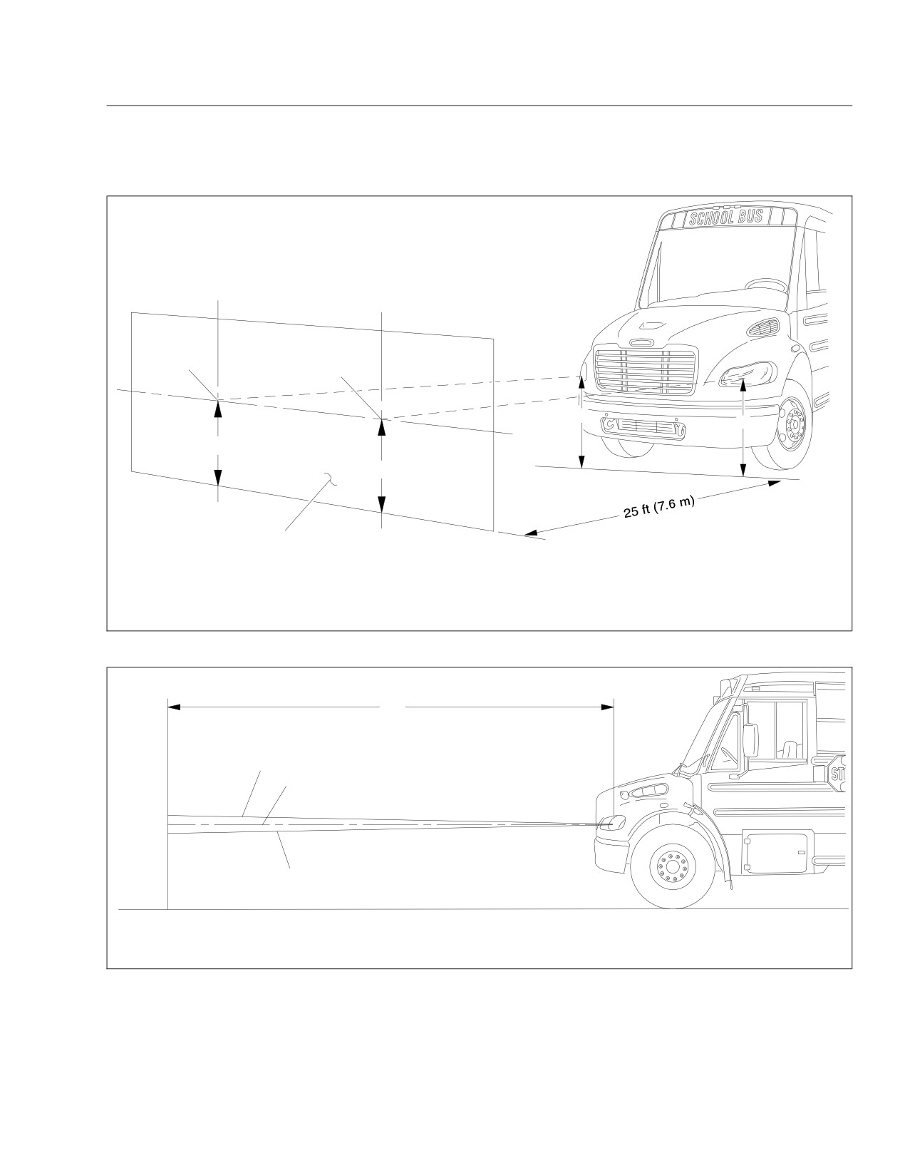
1. Park the vehicle on a level surface, 25 ft (7.6 m)
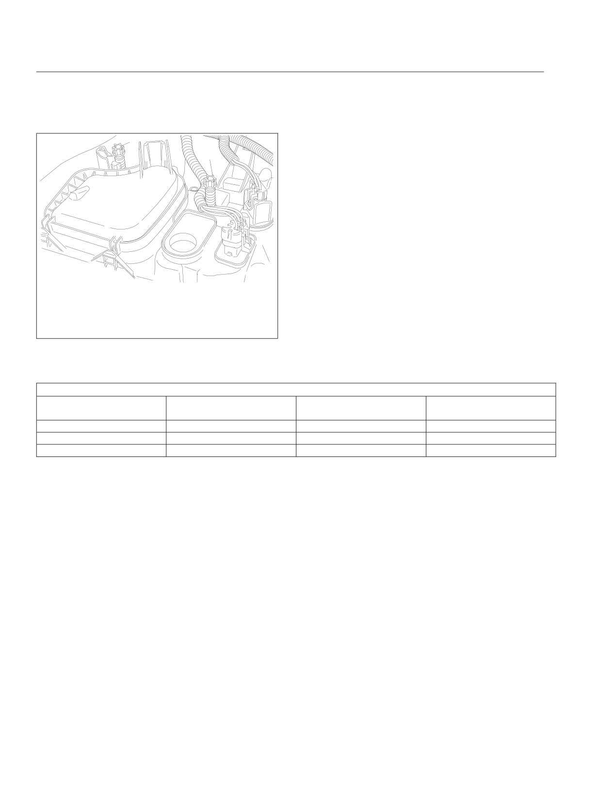
1. Lift the flap over the rear end of the headlight
away from, and perpendicular to, a vertical
bucket to expose the two plastic adjusting knobs
screen or wall. Shut down the engine and set the
on each headlight. See Fig. 15.4.
parking brake. Chock the tires.
2. If necessary, adjust the horizontal positioning of
2. Each headlight has a height adjusting dot. See
the headlights so that each projection points di-
Fig. 15.1. Measure the distance from the ground
rectly forward.
to the height adjusting dot on each headlight.
Note those distances. See Fig. 15.2, Ref. A.
3. Turn the vertical adjustment knob to adjust the
headlight beam to meet the desired height. See
Table 15.1. Turn the knob clockwise to raise the
beam; turn the knob counterclockwise to lower it.
4. Adjust the other headlight.
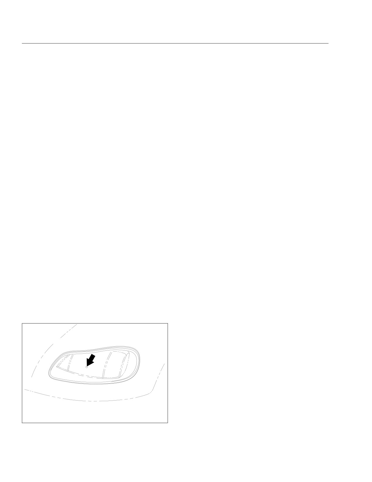
11/06/2002
f544236
Measure beam height from the ground to the small dot
roughly in the center of the headlight lens.
Fig. 15.1, Headlight Beam Height Adjusting Dot
15.1
Headlight Aiming
2
3
A
A
B
B
1
09/11/2012
f545850f
A. Measure the distance from the ground to the center of each headlight bulb.
B. Mark where the center of each headlight projection should appear.
1. Screen or Wall
3. Center of Left-Hand Headlight Projection
2. Center of Right-Hand Headlight Projection
Fig. 15.2, Headlight Aiming Screen/Wall
A
1
2
3
09/26/2012
f545851f
1. Low-Beam Angle Upper Limit
3. Low-Beam Angle Lower Limit
2. Ideal Low-Beam Projection
Fig. 15.3, Vertical Low-Beam Headlight Variation Limits
15.2
Headlight Aiming
1
2
11/05/2002
f544235
NOTE: The right-hand side headlight bucket is shown.
The left-hand side is opposite.
1. Horizontal (inboard) Adjusting Knob
2. Vertical (outboard) Adjusting Knob
Fig. 15.4, Headlight Adjusting Knobs
Vertical Low-Beam Headlight Variation Limits
Distance Between Ground
Desired Variation ( Fig. 15.3,
Upper Limit ( Fig. 15.3, Item
Lower Limit ( Fig. 15.3, Item
and Headlight: in (mm)
Item 2): in (mm)
1): in (mm) up
3): in (mm) down
22-36 (560-900)
0
3.9
(100)
3.9
(100)
36-48 (900-1200)
2
(50) down
2
(50)
6
(150)
48-54 (1200-1400)
2.5
(64) down
1.6
(40)
6.5
(165)
Table 15.1, Vertical Low-Beam Headlight Variation Limits
15.3

16
Hybrid Electric Vehicle
Hybrid Electric Vehicle (HEV) Overview
16.1
Safety Precautions
16.2
Engine Starting and Shutdown
16.2
Eaton Automated Transmission
16.3
Hybrid Electric Vehicle (HEV) System Fault Lamps
16.4
Disabling the Hybrid Electric Vehicle (HEV) System
16.4
In Case of an Emergency
16.5
Jumpstarting
16.6
Towing
16.6
Hybrid Electric Vehicle
IMPORTANT: HSA being active does not mean
Hybrid Electric Vehicle (HEV)
that the brakes are being applied; only that the
Overview
system is prepared to engage the brakes when
needed.
A hybrid electric vehicle (HEV) has both a diesel en-
gine and an electric motor. Engine torque is aug-
While at a stop, the transmission will broadcast the
mented with electrical torque. The electric motor is
J1939 message indicating "ready" or "not ready". If
powered by batteries, which are charged by regen-
the transmission is broadcasting the "not ready" mes-
erative braking.
sage, the ABS will activate HSA. When active, HSA
monitors vehicle speed and brake pressure (force
The batteries cannot move the vehicle for long dis-
applied to the brake pedal). If vehicle speed is 0 and
tances at highway speeds. In the event of a diesel
there is a decrease in brake pressure, HSA will en-
engine failure, drive the vehicle to a safe location as
gage the brakes for up to 3 seconds while it waits for
quickly as possible.
the "ready" message. If the message is not received
Eaton Corporation developed and supplies the hybrid
within 3 seconds, HSA will continue to hold the ve-
electric system for Freightliner Trucks. The primary
hicle for up to 60 seconds. HSA will continue to en-
system components are the hybrid drive unit (HDU),
gage the brake until it receives the message from the
which includes the electric generator/motor and auto-
transmission or the driver reapplies pressure to the
mated transmission, power electronics carrier (PEC),
brake pedal.
and the motor inverter/controller.
If the transmission does not broadcast the "ready"
Freightliner Trucks designed the stand-alone liquid
message within 60 seconds of HSA engaging the
cooling system required to support the operation of
brakes, the ABS system will release the brakes and
Eaton’s HEV system. Its primary system components
the vehicle will roll freely if the driver does not apply
are the electric water pump, reservoir/expansion
pressure to the brake pedal.
tank, radiator, electric radiator fan, and coolant
plumbing.
High-Voltage Safety Features
The HEV has high-voltage safety cables and a ser-
Regenerative Braking
vice switch on the PEC. Areas of the vehicle that
Regenerative braking reduces vehicle speed by con-
contain hazardous voltage are marked with a warn-
verting some of the vehicle’s kinetic energy into elec-
ing label as shown in Fig. 16.1.
tric energy to charge the hybrid system’s batteries.
When the accelerator pedal is at idle while coasting,
or the service brake is depressed to slow the vehicle,
the hybrid system charges the batteries.
WARNING
The regeneration will feel as if the brake is being
HAZARDOUS VOLTAGE
lightly applied when you remove your foot from the
accelerator pedal. The full power of the service brake
INSIDE
is always available to the driver, and regenerative
MAINTENANCE ACCESS ONLY
braking is automatically shut off during an antilock
Failure to follow this warning may
result in property damage,
brake system (ABS) event.
personal injury, or death.
24−01680−000
The Eaton Hybrid Control Unit will automatically shut
10/20/2009
f080164
off regenerative braking when the batteries are fully
charged.
Fig. 16.1, Hazardous Voltage Warning Label
Hill Start Aid
High-voltage safety cables are covered in orange
insulation and labeled near each connector end.
Hill Start Aid (HSA) is a system used on the HEV
Each high-voltage component is tagged with a warn-
Saf-T-Liner C2 School Bus to prevent the vehicle
ing or danger label. See Fig. 16.2.
from rolling backward when it is stopped on a grade,
in gear, and the driver is not applying the service
brake.
16.1
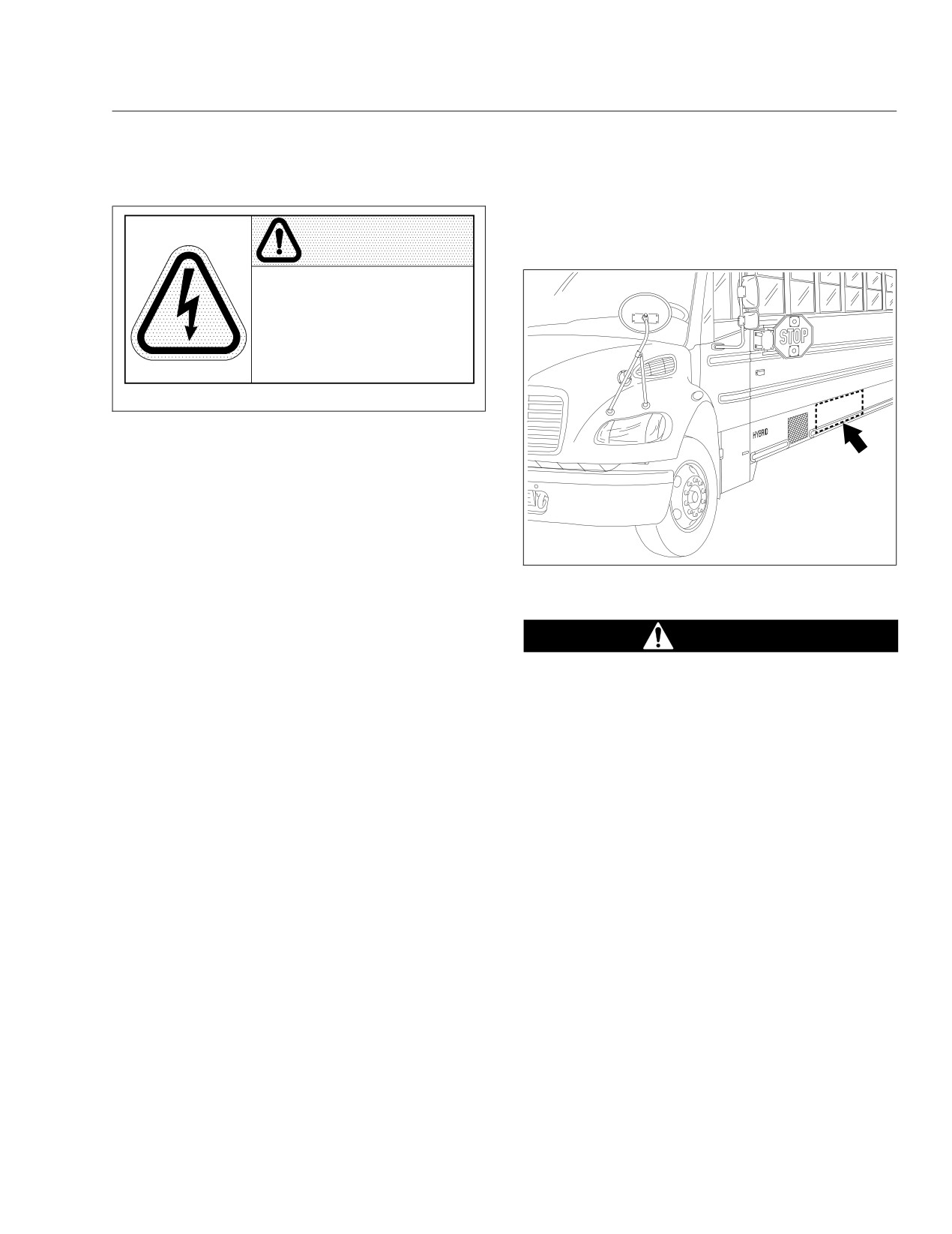
Hybrid Electric Vehicle
cutting equipment, avoid high-voltage cables and the
Power Electronics Carrier (PEC). See Fig. 16.3 for
WARNING
the location of the high-voltage cables and PEC.
HAZARDOUS VOLTAGE
DO NOT CUT INTO ORANGE
HIGH VOLTAGE CABLES
Failure to follow this warning may
result in property damage,
personal injury, or death.
24−01677−000
10/20/2009
f080163
Fig. 16.2, High Voltage Cables Warning Label
IMPORTANT: The service switch on the PEC
should only be used for an emergency shut-
down, or when the service manual or trouble-
shooting guide calls for work on the high-voltage
system. The service manual and troubleshooting
guide for the hybrid electric system are available
04/17/2009
f545509
from www.roadranger.com.
Fig. 16.3, High Voltage Cables and Power Electronics
The red service switch is located next to the high-
Carrier (PEC) Location
voltage cable connections at one end of the PEC.
Pushing in the red service switch will shut down the
DANGER
engine. The hybrid system will be disabled, and the
high-voltage batteries in the PEC, though still live,
Unprotected contact with any live high-voltage
are isolated in the PEC.
components can cause serious injury or death.
NOTE: The PEC may be mounted in an area
Avoid direct pressure wash on high-voltage PEC
with limited access.
connections and the air intake and exhaust on the
For emergency shutdown information, see "In Case
PEC.
of an Emergency" in this chapter.
Engine Starting and Shutdown
Cooling System
The Cranking System
The HEV requires a liquid cooling system for the
HDU, inverter, and DC/DC converter. The HEV cool-
The primary engine starter is the electric motor in the
ing system is separate from the engine cooling sys-
HDU. The back-up cranking system is the standard
tem.
12-volt starter on the engine. If the hybrid system is
offline or the hybrid batteries are insufficiently
For coolant, use a 50/50 mixture of water and
charged, the vehicle will automatically use the 12-volt
extended-life antifreeze—the same coolant specified
cranking system to start the engine.
for the vehicle.
Starting
Safety Precautions
1. Set the parking brake.
The HEV has high-voltage components, including
2. Turn the ignition switch to the ON position.
340-volt Direct Current (DC) batteries and a 500-volt
Alternating Current (AC) motor.
Wait for the gauges on the instrument panel to
complete two sweeps (one from left to right, and
Never touch or cut high-voltage cables or connec-
tors. If it is necessary to remove occupants using
16.2
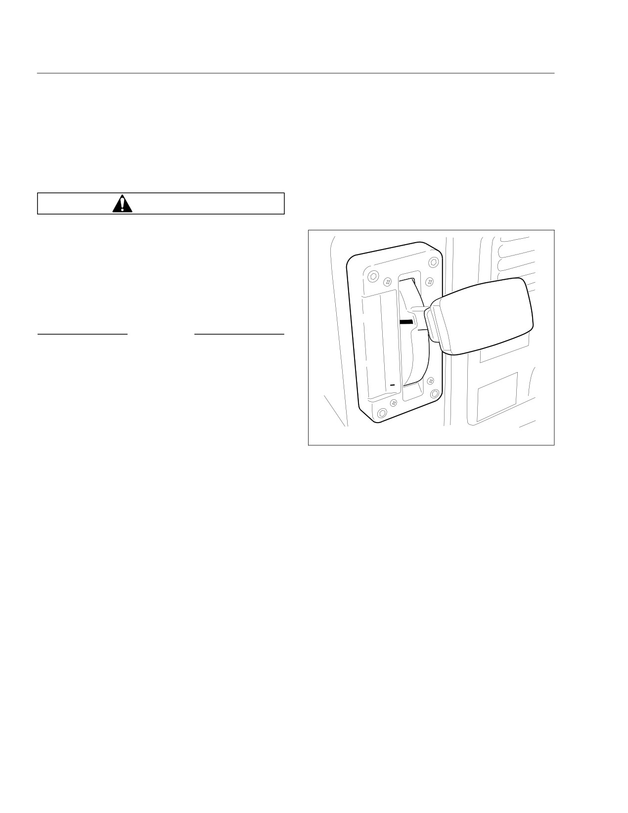
Hybrid Electric Vehicle
one from right to left) and return to their normal
Eaton Automated
ranges.
Transmission
3. Make sure that the transmission shift control is in
the Neutral (N) or Park (P) position.
The Hybrid Saf-T-Liner C2 School Bus is equipped
with an Eaton automated transmission. A T-handle
shift control is used by the driver to select the trans-
WARNING
mission ranges. See Fig. 16.4.
Never start the engine unless the parking brake
is applied. Accidental movement of the vehicle
could result in property damage, personal injury,
or death.
NOTE: The vehicle will crank after a brief delay.
4. Turn the ignition switch to the START position.
P
After the engine starts, release the key.
R
NOTICE
N
D
Do not crank the engine for more than 30 sec-
H
onds at a time. Wait two minutes after each try to
allow the starter to cool. Failure to do so could
1
cause starter damage.
5. Apply the service brake, then release the parking
brake.
04/15/2009
f270160a
6. With the service brake applied, press the desired
mode on the shift control to put the vehicle in
Fig. 16.4, T-Handle Shift Control (hybrid vehicle)
gear, then slowly release the service brake.
NOTE: The vehicle may be powered by the
P (Park)
electric motor or the diesel engine, depending
Use park when turning the engine on or off, to check
on battery charge and the demand for driveline
vehicle accessories, or to operate the engine in idle
torque. If the electric motor alone is powering
for longer than 5 minutes. This position places the
the driveline, the diesel engine will stay at idle.
transmission in neutral and engages the park pawl of
the transmission.
Engine Shutdown
NOTE: This does not apply the parking brake.
IMPORTANT: The transmission must be in neu-
The park pawl effectively grounds the transmis-
tral for proper shutdown.
sion output shaft, thereby preventing rotation of
1. With the vehicle stopped, place the transmission
the driveline. Provided the vehicle is stationary,
in Neutral (N).
selecting P (park) on the shift selector places
2. Set the parking brake.
the transmission in Neutral and engages the
park pawl.
3. Shut down the engine by turning the ignition
switch to the OFF position.
R (Reverse)
NOTE: Intermittent noises such as clicking and
The reverse position selects the reverse gear once
transmission shifting may be audible from the
the vehicle speed is less than 2 mph (3 km). When
transmission while it completes a self-test and
the selector is in reverse, the reverse warning signal
shutdown.
will sound. Always bring the vehicle to a complete
16.3
Hybrid Electric Vehicle
stop before shifting from a forward range to reverse,
Hybrid Electric Vehicle (HEV)
or from reverse to a forward range.
System Fault Lamps
Do not idle in reverse for more than 5 minutes. Se-
lect P (park), or N (neutral) when time at idle ex-
There are two lamps on the dashboard that indicate
ceeds 5 minutes.
a hybrid system fault is active—the red STOP HY-
BRID lamp and the amber CHECK HYBRID lamp.
N (Neutral)
See Fig. 16.5. When the red STOP HYBRID lamp is
illuminated, do not drive the vehicle; have it towed to
The neutral position places the transmission in neu-
a Thomas Built Bus dealer or an authorized service
tral. This position is used when starting the engine
center for repairs. When the amber CHECK HYBRID
and for stationary operation.
lamp is illuminated, the vehicle can still be driven,
When neutral is selected, the vehicle service brakes,
though it may operate without the assistance of the
parking brake, or emergency brake must be applied.
hybrid electrical system.
Selecting neutral does not apply vehicle brakes un-
less an auxiliary system to apply the parking brake is
installed.
Do not let the vehicle coast in neutral. If the vehicle
CHECK
is allowed to coast in neutral, the engine brake will
HYBRID
not work and you could lose control of the vehicle.
D (Drive)
STOP
HYBRID
The drive position selects the default start gear and
automatically upshifts and downshifts. In the drive
position, the transmission will initially go into first
range when drive is selected. As vehicle speed in-
07/09/2008
f611013
creases, the transmission will upshift automatically
Fig. 16.5, Hybrid System Fault Lamps
through each available range up to fourth range or
fifth range. As the vehicle slows, the transmission will
A gear display, located on the dash above the fault
downshift automatically.
lamps, will show the current gear selected, and any
When going downhill, downshift to a lower transmis-
fault codes for the transmission. F will flash for a
sion range to increase engine braking and to help
fault code, and the hybrid system fault lamps will illu-
maintain control. During downhill operation, the trans-
minate. If the gear display flashes CA, the driver is
mission may upshift to the next higher range, if the
being notified about clutch abuse.
engine is exceeding its governed speed in the lower
range.
Disabling the Hybrid Electric
H (Hold)
Vehicle (HEV) System
The hold position on the T-handle shifter holds the
The following information describes the three meth-
transmission in the current gear.
ods to disable the HEV system.
1
(Low Gear)
Option 1 (preferred method)
Use first range when pulling through mud or deep
Turn off the ignition.
snow, when maneuvering in tight spaces, or when
• The engine, dash lights, and HEV system will
driving up or down very steep grades. First range
shut down.
provides the vehicle with its maximum driving torque
and maximum engine braking effect.
• The HEV batteries are still active, but are iso-
lated in the Power Electronics Carrier (PEC).
16.4
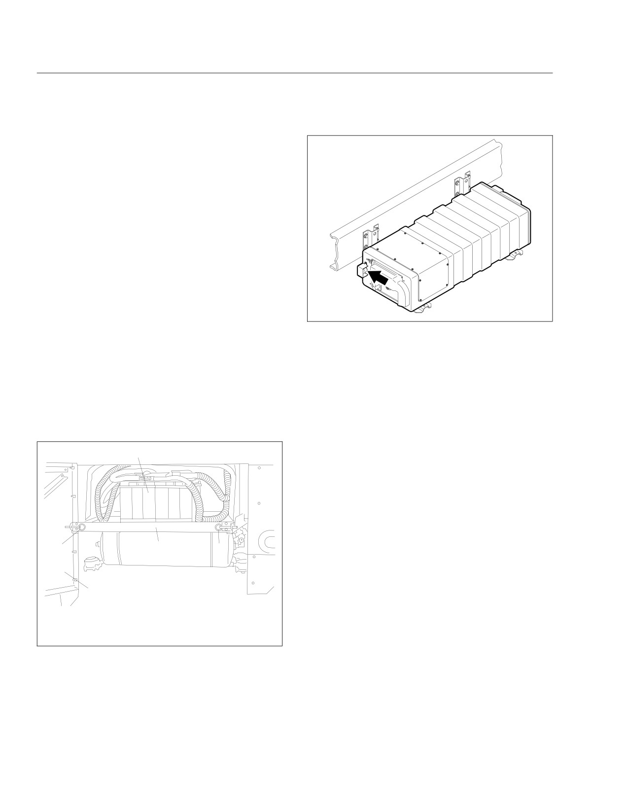
Hybrid Electric Vehicle
Option 2
Disconnect the low-voltage (12 volt) vehicle batteries.
See Fig. 16.6.
• The engine and HEV system will shut down.
• The HEV batteries are still active, but are iso-
lated in the PEC.
Option 3
Push in the service switch on the PEC and shut
down the engine.
IMPORTANT: The red service switch on the
PEC should only be used for an emergency
shutdown or when the service manual or
04/22/2009
f545519
troubleshooting guide directs the hybrid-trained
Fig. 16.7, Service Switch
technician to perform work on the high-voltage
system.
down" procedure found in TRSM1000 located
on www.roadranger.com.
• Push in the service switch on the PEC and
shut down the engine. See Fig. 16.7.
In Case of an Emergency
• The hybrid system will be disabled.
Emergency Shutdown
• The HEV batteries are still "live" but are iso-
lated in the PEC.
IMPORTANT: After disabling the vehicle, power
is maintained in the high-voltage electrical sys-
4
tem for up to 5 minutes.
There are three options for performing an emergency
shutdown. The preferred method is to turn off the
ignition key. The second option is to disconnect the
low-voltage (12-volt) vehicle batteries. The final
method is to push in the service switch on the Power
Electronics Carrier (PEC). In any case, the engine,
dash lights, and hybrid electrical system will shut
2
3
2
down. The high-voltage batteries in the PEC will re-
main "live" but isolated in the PEC.
In Case of an Accident or Fire
1
If the HEV becomes involved in an accident or fire,
12/05/2003
f544365
be aware of the following:
1. Battery Access Door
3. Battery Tray
• Use CO2 or dry chemical extinguishers.
2. Pull-Pin Spring Latch
4. Battery
Lithium ion batteries are contained in the
Fig. 16.6, Battery Access
Power Electronics Carrier (PEC).
• Do not cut into high-voltage cables. The high-
IMPORTANT: These procedures should only be
voltage wiring is covered in orange insulation
used for an emergency. If service is required on
or convoluted tubing and marked with warning
the vehicle, refer to the "Hybrid Services Shut-
labels at the connectors.
• Do not cut into or open the PEC.
16.5

Hybrid Electric Vehicle
• Do not cut into or open the inverter.
If it is necessary to remove occupants using cutting
equipment, avoid high-voltage cables and the PEC.
See Fig. 16.3 for the location of the high-voltage
cables and PEC.
Jumpstarting
Jumpstarting vehicles equipped with the Eaton® Hy-
brid System is identical to non-hybrid vehicles, which
use the vehicle 12-volt battery system. See Chap-
ter 14 for jumpstarting instructions.
Towing
NOTICE
When towing or pushing the vehicle, regardless
of the distance or speed traveled, either discon-
nect the driveshaft at the rear axle and support it
as necessary, or remove the axle shafts. Failure
to do this when towing the vehicle with the rear
wheels on the ground could result in damage to
the transmission and other parts.
For instructions, see "Towing" in Chapter 14.
16.6

17
Propane Fuel System
General Information
17.1
Ignition Switch and Key
17.1
Engine Operation
17.2
Propane Refueling
17.3
Ametek Instrument Panel
17.5
Warning and Indicator Lights
17.10
Speedometer and Tachometer
17.18
Standard Instruments
17.19
Grade Brake
17.20

Propane Fuel System
with a minimum of 90% propane and a maximum of
General Information
5% propylene. This grade of propane is 100 plus oc-
tane and provides proper performance and emissions
CAUTION
control, which the fuel system is designed to deliver.
The engine is designed to operate properly on a
The propane fuel system requires special tools to
wide variety of liquid propane gas (LPG) blends
make repairs. Service and repair of the propane
which can fall in the category of HD5, and is not af-
fuel system should only be performed by trained
fected by "heavy ends" or other waxy hydrocarbons
propane service technicians. To prevent personal
that have traditionally affected other systems.
injury or damage to the fuel system, do not at-
tempt repairs yourself.
NOTICE
DANGER
LPG should be free of contaminants including,
but not limited to, rust, dirt, sand, water, salt, and
Never cut or weld on the propane storage tank.
brine. These contaminants can cause engine
Severe bodily injury or fire could result.
damage that is not covered by the engine war-
Propane is highly flammable. Keep sparks and
ranty.
open flames away from propane. Do not smoke
when refueling the vehicle. Failure to observe
WARNING
these safety precautions could cause serious
bodily injury or death.
The propane fuel system operates at pressures
The information provided in this chapter is specific to
up to 312 psi (2151 kPa). A sudden release of
the propane engine, however, other chapters in this
propane can cause serious injuries if it contacts
manual pertain to the propane operated vehicle.
the skin or eyes. Always wear approved protec-
These include, but are not limited to, the controls and
tive gloves and eye protection when handling
pretrip inspection and daily maintenance chapters.
propane.
IMPORTANT: For assistance with propane en-
LPG has no color. A distinctive odorant, similar to
gine related questions, contact Powertrain Inte-
sulfur or rotten eggs, is added to LPG to alert any-
one nearby in the event of a leak.
gration at 1-877-336-6308.
NOTE: Oil consumption is normal during opera-
Body Heater Loop Valve
tion of the propane engine. The rate of con-
The body heater loop valve circulates hot coolant to
sumption is highly dependent on vehicle loading
the body heaters, thereby providing heat inside the
and duty cycles. New engines may experience
vehicle.
higher oil consumption during the engine
break-in period. For further information, refer to
NOTICE
the engine manufacturer’s manual or contact
Powertrain Integration.
The body heater loop valve must be closed be-
fore operating the vehicle in temperatures of
NOTICE
100°F (38°C) or higher. Failure to do so could re-
sult in the loss of engine coolant, and cause en-
If the ignition switch is in the RUN position for
gine damage over time. See Fig. 17.1.
more than 15 seconds and the fuel tank is empty,
the fuel pump must be unplugged. Failure to fol-
Ignition Switch and Key
low this procedure will result in damage to the
fuel pump. Refer to the propane engine manual
The ignition switch has four positions: ACCESSORY,
for instructions on how to unplug the fuel pump.
OFF, RUN, and START. See Fig. 17.2.
HD5 grade propane is recommended for propane
In the OFF position, the key slot is vertical; the key
engines. HD5 is a heavy duty engine grade propane
can be inserted and removed only in this position.
17.1
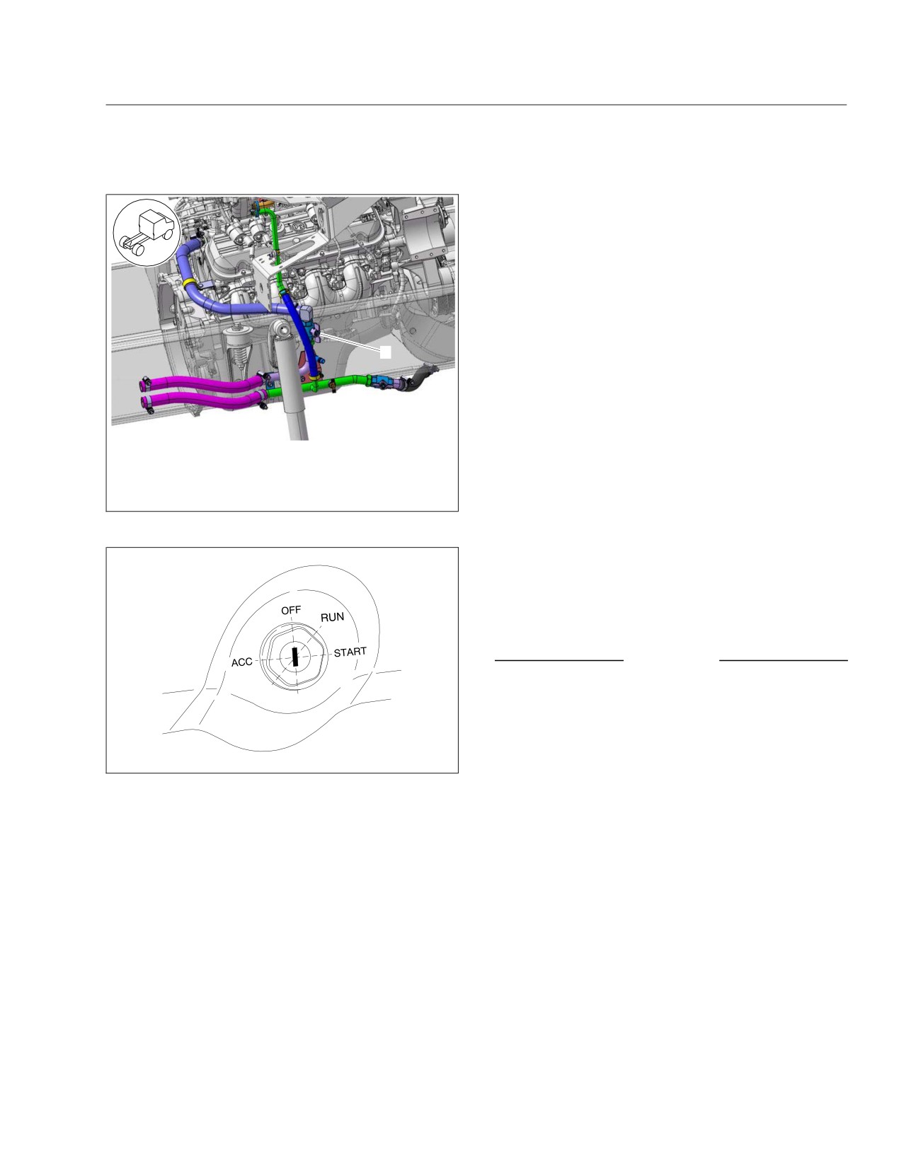
Propane Fuel System
pressure and low oil pressure operate until minimum
pressures are built up.
IMPORTANT: The propane engine is equipped
with an amber wait to start indicator. The indica-
tor light illuminates when the ignition is in the
RUN position prior to engine start-up. Do not
crank the engine until the wait to start indicator
light goes out. See the "Ametek Panel" informa-
tion in this chapter for the location of the wait to
1
start indicator.
Turn the key fully clockwise to the START position to
start the engine. When the engine starts, release the
key.
12/09/2013
f200840
Engine Operation
To close the valve, it must be rotated 90 degrees so
that it is perpendicular to the coolant lines.
General Information
1. Body Heater Loop Valve
NOTE: Before starting the engine, read the
Fig. 17.1, Body Heater Loop Valve
"Ametek Panel" information in this chapter and
Chapter 5 for detailed information on how to
read the instruments and operate the controls.
Before operating the vehicle, perform the pretrip in-
spection and daily maintenance checks in Chap-
ter 11 and Chapter 12 of this manual.
NOTICE
If a vehicle does not start on the first attempt,
make sure that the engine has completely
stopped rotating before reapplying the starter
switch. Failure to do so can cause the pinion to
08/27/2013
f610509a
release and re-engage, which could cause ring
gear and starter pinion damage.
Fig. 17.2, Ignition Switch Positions
Moving a vehicle with the starter and/or using the
The following can be operated in the OFF position
starter to bump the engine for maintenance pro-
(regardless of whether the key is inserted): low beam
cedures is strictly prohibited. Use of these meth-
headlights, taillights, brake lights, road lights, clear-
ods to bump the engine over or move the vehicle
ance lights, turn signals, hazard warning lights, horn,
can cause the pinion to release and re-engage,
CB radio, clock, and electric oil pan heater.
which could cause ring gear and starter pinion
damage.
In the ACCESSORY position, the key is turned coun-
terclockwise. The radio (if so equipped), mirror heat,
Engine Starting
air dryer, backup lights, and all of the components
that are operable in the OFF position are operable in
1. Set the parking brake.
the ACCESSORY position.
2. Turn the ignition switch to the RUN position.
All electrical systems are operable in the RUN posi-
The amber wait to start indicator light illuminates
tion. The warning lights and the buzzer for low air
when the ignition is in the RUN position prior to
17.2

Propane Fuel System
engine start-up. Do not crank the engine until the
1. With the vehicle stopped, place the transmission
wait to start indicator light goes out.
in Neutral (N), or if so equipped, the Park (P)
position.
3. Make sure that the transmission shift control is in
Neutral (N), or if so equipped, the Park (P) posi-
2. Set the parking brake.
tion.
3. Idle the engine for two to three minutes before
shutting it down. This allows the lubricating oil
WARNING
and the coolant to carry heat away from the
combustion chambers, bearings, shafts, etc.
Never start the engine unless the parking brake
is applied. Accidental movement of the vehicle
NOTE: Long periods of idling are not needed or
could result in property damage, personal injury,
recommended.
or death.
4. Shut down the engine by turning the ignition
IMPORTANT: Do not depress the throttle pedal
switch to the OFF position.
while starting the engine.
Propane Refueling
4. Turn the ignition switch to the START position.
After the engine starts, release the key.
CleanFuel USA recommends that the Liquid Propane
Injection® (LPI) vehicle be refilled with fuel at sta-
NOTICE
tions that are specifically designed for vehicle refuel-
ing. For assistance locating LPG fuel stations, con-
Do not crank the engine for more than 30 sec-
onds at a time. Wait two minutes after each try to
1-512-864-0300.
allow the starter to cool. Failure to do so could
The propane fuel system utilizes a closed system,
cause starter damage.
with fuel supply and return lines. This requires more
5. Bring the engine up to operating speed gradually
advanced refueling equipment due to variances in
as it warms up and develops stable oil pressure.
pressure. When refueling the vehicle at a station not
specifically designed for dispensing propane (also
IMPORTANT: When the engine is started, it
referred to as autogas), the refueling process may be
takes a short time to build up a lubricating oil
very slow or the tank may not fill at all. The vehicle
film between the shafts and bearings, and be-
propane tank is subjected to heat from the pavement
tween the pistons and cylinder walls. The oil
and chassis components, which cause a normal in-
pressure gauge indicates any drop in lubricating
crease in tank pressure. The station pump may not
oil pressure within 15 seconds of engine startup.
be able to produce pressure high enough to over-
come that of the tank on the vehicle. It is recom-
Engine Shutdown
mended that the filling dispenser have a minimum of
90 psi (621 kPa) pump differential boost pressure
Shut down the engine immediately if:
over the storage tank pressure; most modern sta-
tions are designed to 130 psi (896 kPa) differential
• the oil pressure gauge needle swings back and
pressure. It is recommended to refuel the vehicle at
forth or falls sharply;
a modern station to prevent any customer inconve-
• engine power and rpm fall, even though the
nience.
accelerator pedal remains steady;
LPI fuel tanks are equipped with both an 80% fixed
• the exhaust pipe gives off heavy smoke;
liquid level gauge, and an automatic overfill protec-
tion device (OPD). The LPI system is designed to be
• the coolant and/or oil temperature climb abnor-
filled reliably and safely using only the OPD. There-
mally;
fore, it is not recommended to use the 80% fixed liq-
• abnormal sounds suddenly occur in the engine.
uid level gauge unless required by the filling station
attendant, or for annual OPD verification. See the
17.3

Propane Fuel System
CleanFuel USA Owners Manual Supplement for in-
this could result in serious injury. Replace the
structions on how to perform the annual OPD verifi-
O-ring before connecting the propane fill nozzle.
cation test.
6. Connect the propane fill nozzle to the tank fill
valve.
CAUTION
7. Rotate the propane fill valve nozzle clockwise
Liquid propane can cause serious burns should
until is is firmly attached to the tank fill valve.
it contact the skin or eyes. When handling pro-
8. Close the fill nozzle vent valve if so equipped.
pane, always wear approved protective gloves
and eye protection to prevent contact.
9. Open the 80% bleeder valve only if required.
CleanFuel USA does not recommend using the
Propane is extremely flammable, and can ignite if
bleeder valve. Use of the valve in a low emission
an ignition source is present, causing burns and
fuel station is prohibited.
other serious injuries. Keep sparks and flames
away from propane. Do not smoke near propane
10. Open the valve on the refueling nozzle.
or when refueling the vehicle.
11. Turn the propane dispenser on to begin refuel-
Propane is stored in the fuel tank under high
ing.
pressure. Never fill a leaking or damaged tank, as
12. When the OPD stops the flow of fuel into the
this could result in serious injury. Have the ve-
tank, close the filling valve.
hicle fuel tank(s) and fuel system inspected for
leaks by a trained technician annually.
If use of the 80% bleeder valve is required, stop
filling when liquid from the bleeder appears in the
Propane is a liquid under pressure and is stored in a
form of a white cloudy vapor.
pressure vessel unlike a gasoline or diesel tank. A
propane tank must never be filled to more than 80%
13. Turn the propane dispenser off.
of its actual capacity, to allow room for expansion.
80% is considered "full" for all propane tanks. When
CAUTION
the tank is filled to the correct 80% level, the fuel
gauge should read full.
Never overfill the propane fuel tank. Overfilling
the fuel tank can cause a dangerous condition,
The following steps describe a typical refueling pro-
resulting in serious injury and damage to the ve-
cedure. See Fig. 17.3 for an example of the dual
hicle.
propane tank system.
After refueling, if a strong smell of propane per-
1. Park the vehicle on level ground to ensure that
sists or if a hissing sound is heard, notify the
the tank is properly filled.
fuel station operator. Do not start the vehicle.
2. Turn the vehicle ignition to OFF and set the park-
14. Disconnect the filling nozzle from the tank fill
ing brake. Chock the tires if required.
valve.
3. Ensure that there are no open flames or ignition
14.1
If necessary, first open the vent valve on
sources in the area.
the nozzle, if so equipped, and release the
4. Turn the fuel tank cap counterclockwise and re-
pressure from the valve for safety.
move it.
14.2
Rotate the filling nozzle connector coun-
5. Inspect the fill valve O-ring, making certain the
terclockwise and remove it. Then return it
O-ring is seated in the groove and is not dam-
to the dispenser.
aged or missing.
15. Install the fuel cap.
CAUTION
16. Check for leaks on the fill valve and connecting
piping, and around the 80% bleeder valve.
Never connect the propane fill nozzle to the tank
17. Ensure that all of the fuel tank valves are in the
fill valve if the O-ring is damaged or missing, as
fully-closed position.
17.4
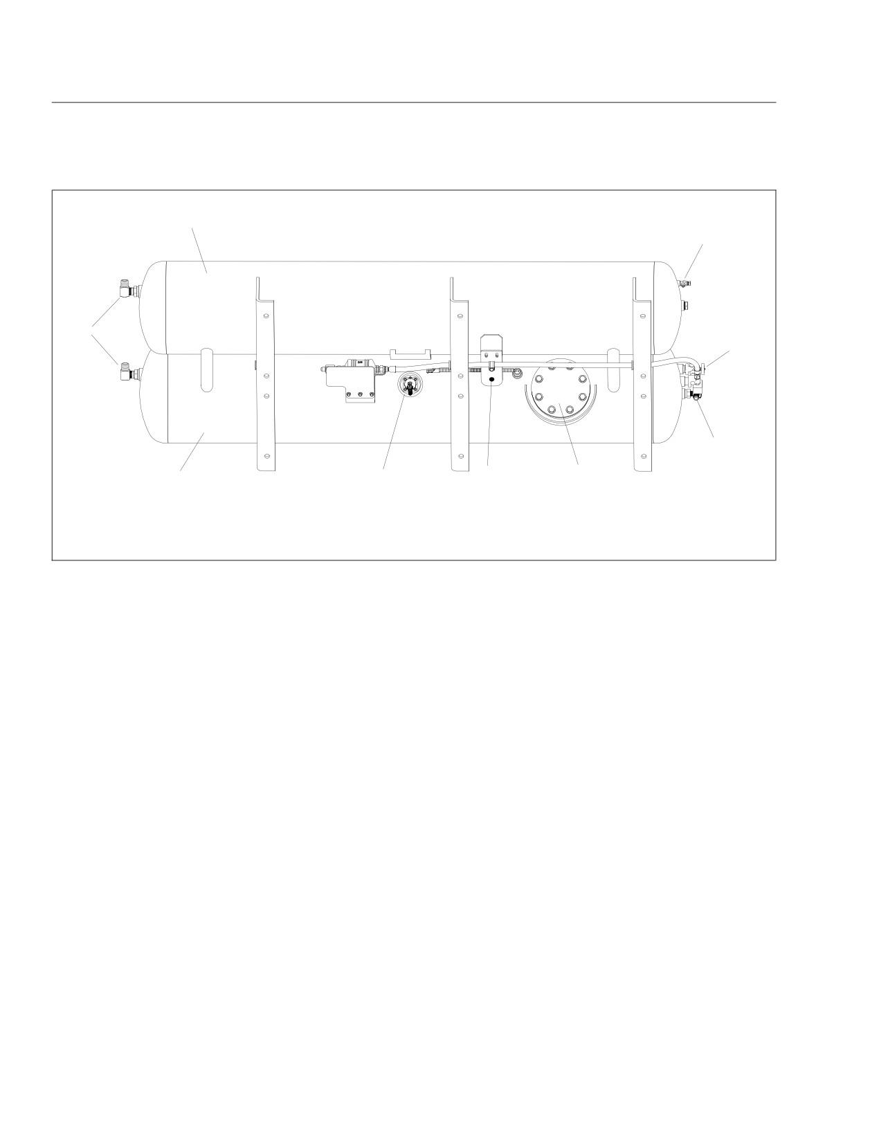
Propane Fuel System
1
2
9
3
4
6
5
8
7
09/18/2013
f470605
1. Propane Tank
4. Return Valve
7. Fuel Level Gauge
2. Bleeder Valve
5. Access Cover and Collar
8. Propane Tank
3. Fill Valve
6. Service Valve
9. Pressure Relief Valves
Fig. 17.3, Dual Propane Tank System
• Hour Meter
Ametek Instrument Panel
• Boost Pressure
The following information describes the Ametek in-
strument panel, used with liquid propane gas (LPG)
• Engine Oil Pressure
engines. The instrument panel is shown in Fig. 17.4.
• Coolant Temperature
NOTE: The instrument panel is shown with a
• Fuel Level
standard U.S. speedometer, which shows miles
per hour (mph) more prominently than kilome-
• Percent Engine Load
ters per hour (km/h).
• Engine RPM
During normal operation, the LCD displays the odom-
Message Display Center
eter value and chassis battery voltage on the top
The message display is a graphical, backlit, liquid
line, and driver selected parameters, such as the trip
crystal display (LCD) that relays information to the
odometer and fuel rate, on the second and third
vehicle operator. The messages displayed include:
lines.
• Odometer
Priority Messages
• Trip Odometer 1/Trip Odometer 2
Priority messages (including warning messages) are
• Chassis Battery Voltage
displayed in the LCD due to various inputs or data
messages. Unless noted otherwise, the priority mes-
• Instantaneous Fuel Rate
sage will take over the whole screen, allowing mul-
• Average Fuel Rate
tiple messages to be displayed in five second inter-
vals.
• Gear Attained Status
• Transmission Temperature
17.5
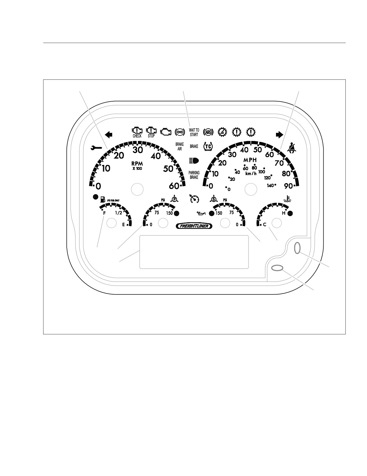
Propane Fuel System
1
2
3
6
7
4
5
8
10
9
12/05/2012
f611202
1. Tachometer
5. Primary Air Pressure Gauge
8. Dash Driver Display Screen
2. Dash Message Center
6. Secondary Air Pressure Gauge
9. Toggle Button, Down
3. Speedometer
7. Coolant Temperature Gauge
10. Toggle Button, Right
4. Fuel Level Gauge
Fig. 17.4, Gauge Layout (typical, U.S.), LPG Engines
Self-Test
Menu System
When the ignition is turned on, a required self-test
The menu system is shown on the driver display
automatically begins. Gauge needles will reset to
screen once the self-test is finished. The menu sys-
zero during the self-test, and then immediately move
tem responds to input from the driver and remains
to the position dictated by the data received. During
active as long as the ignition is on. In order for the
this time, the warning lights, alarm (buzzer), and
driver to operate the menu system, the ignition must
driver display screen will also perform a self-test.
be ON, and the park brake must be set (ON). The
main features of the menu system are described
NOTE: The driver can activate or deactivate the
below.
start-up self-test by accessing the setup menu.
17.6

Propane Fuel System
• Setup—this is used to set various parameters,
• maintenance intervals
which are saved when the ignition is turned off.
• transmission oil life remaining
Setup has select display units, startup screen,
LCD contrast, and reset parameters.
• transmission oil filter life monitor
• Maintenance—shows various maintenance in-
Maintenance Intervals
tervals such as engine oil, air filter, etc.
The maintenance intervals menu allows the driver to
• Diagnostics—this is used for setting and read-
set the change intervals for engine oil and engine air
ing inputs and outputs and checking the
filter. If the intervals are set to zero, the maintenance
gauges. It also shows the hardware and soft-
warnings must be disabled.
ware version of the instrument panel, and has
menus to retrieve active error codes from the
Transmission Oil Life Remaining
engine, transmission, and ABS controllers.
If transmission prognostics are enabled, this menu
NOTE: No lines can be highlighted in the menu
indicates how much useful oil life remains.
system screen. To get to the sections that can
be highlighted, press the right arrow toggle but-
Transmission Oil Filter Life Monitor
ton and hold it for two seconds. The display
If transmission prognostics are enabled, the trans-
screen will change and the options shown can
mission oil filter life monitor tells the driver if the
then be highlighted. Once a selection has been
transmission oil filter is clogged and in need of repair.
chosen and changes are made, press the right
A message will appear on the display screen as
arrow toggle button to go back to the main mes-
TRANS OIL FILTER FUNCTIONAL or TRANS OIL
FILTER CLOGGED.
sage display screen.
Diagnostic Menu
Setup Menu
Select Display Units
The diagnostic menu contains the following items:
The set units screen allows the driver to choose be-
• engine faults
tween English or metric units of measurement for the
• transmission faults
displayed values. To navigate to the set units screen,
see Fig. 17.5, screens H, I, and J.
• ABS faults
• check outputs
Startup Screen
The startup screen selection allows the driver to turn
• odometer diagnostics
the startup screen on or off.
• check gauges
LCD Contrast
• check indicators (warning lamps)
Select contrast from the menu to set the LCD con-
• check LCD
trast. Use the down toggle button to set the contrast
• check binary inputs
to the desired level. To navigate to the contrast
screen, see Fig. 17.5, screen M.
• check analog inputs
Reset Parameters
• check datalink
The reset parameters screen is included with ve-
• hardware/software version
hicles that have the Allison transmission prognostics
All of the items in the diagnostic menu can be ac-
feature.
cessed by using the toggle buttons and selecting the
auxiliary screens. Then navigate to the diagnostic
Maintenance Menu
sub-menu. Some of the more frequently used diag-
The maintenance menu has the following three sub
nostic menus are described further below.
menus:
17.7
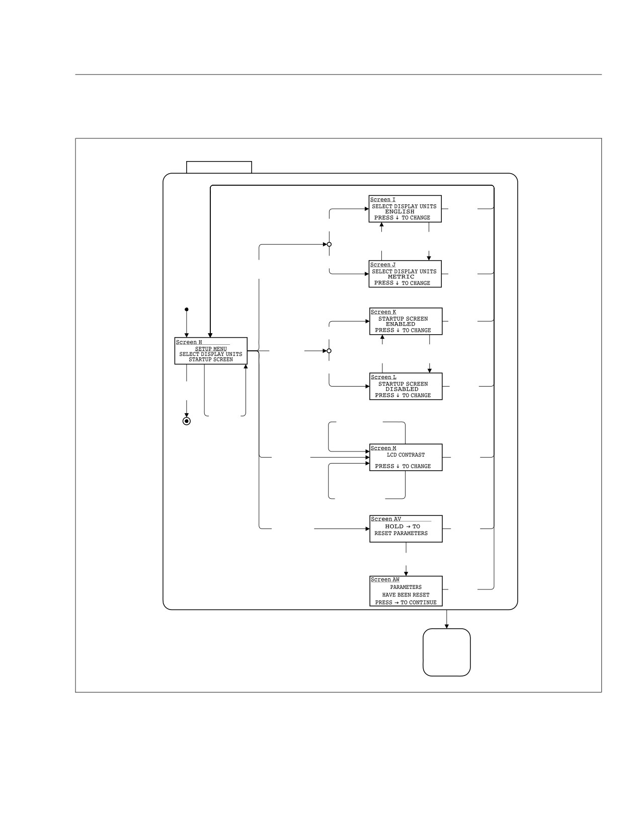
Propane Fuel System
SETUP
Right Press
Or
Down Hold
Current Units =
English
Down Press
Down Press
Current Units =
Current Units =
English
Metric
Current Units =
Right Press
Metric
Select Display
Right Press
Units highlighted
Or
Down Hold
Right Press
Or
Down Hold
Startup Screen =
Enabled
Right Press
Down Press
Down Press
Startup Screen
Startup Screen =
Startup Screen =
highlighted
Enabled
Disabled
Startup Screen =
Disabled
Right Press
Down Hold
Or
Or (Right & Exit
Down Hold
highlighted)
Down Press
Highlight next
line of list.
Down Press
At middle,
At Min Contrast /
wrap to top
Set Contrast to Max
Right Press
Right Press
Display Contrast
Or
highlighted
Down Hold
Down Press
Not At Min Contrast /
Decrease Contrast
Right Press
Right Press
Reset Parameters
Or
highlighted
Down Hold
Right Hold
Reset Parameters
Right Press
Or
Down Hold
AUXILIARY
SCREENS
09/23/2009
f040792
Fig. 17.5, Setup Menu Screens
17.8

Propane Fuel System
Engine Faults
fined in the system. The toggle buttons allow the
driver to select each analog input. This information is
This screen displays engine fault codes that are re-
continuously updated to assist in troubleshooting. To
ceived from the engine electronic control unit (ECU).
navigate to the check analog input screen, see
To navigate to the engine fault screen, see Fig. 17.6,
Fig. 17.8, screen AK.
screen AA.
Check Datalink
Transmission Faults
The check datalink screen allows the driver to view
This screen displays transmission fault codes that
all devices that communicate on the J1939, J1587,
are received from the transmission ECU. To navigate
and GMLAN datalinks. To navigate to the check da-
to the transmission fault screen, see Fig. 17.6,
talink screen, see Fig. 17.8, screen AL.
screen AB.
Menu Navigation
ABS Diagnostics
This screen displays Antilock Brake System (ABS)
The menu navigation screens are provided to illus-
fault codes that are received from the ABS ECU. To
trate the menu system. The paths to specific screens
navigate to the ABS diagnostic screen, see Fig. 17.6,
are shown, along with instructions for using the
screen AC.
toggle buttons to move from one screen to another.
See Fig. 17.5, Fig. 17.6, Fig. 17.7, Fig. 17.8,
Check Gauges
Fig. 17.9, Fig. 17.10, Fig. 17.11, Fig. 17.12,
Fig. 17.13, Fig. 17.14, Fig. 17.15, Fig. 17.16, and
The check gauges screen allows the driver to set
Fig. 17.17.
each gauge as a percentage of scale (either 0, 50, or
100%), as shown in the LCD. To navigate to the
IMPORTANT: Follow the steps below to change
check gauges screen, see Fig. 17.7, AG screens.
the three items (also known as favorites) shown
in the message display center. The message
Warning Lamp
display center is referred to as screen C in
The warning lamp screen allows the driver to test
Fig. 17.11.
each warning lamp (not the vehicle load) on and then
NOTE: The driver can check the pressure of the
off, displaying the lamp name and status in the LCD.
To navigate to the warning lamp screen, see
propane in the fuel rail (pressure of the fuel in
Fig. 17.7, screen AH.
both the tank and pump booster), and make this
one of the three items shown in the message
Check LCD
display center. Select the item with the fuel
pump and psi reading, then follow the directions
Selecting the check LCD screen displays the Freight-
liner Custom Chassis Corporation (FCCC) logo in
below to make it one of the favorites.
normal and reverse video three times and then re-
1. With the vehicle in park, turn the ignition to RUN,
turns to the menu. To navigate to the check LCD
and allow the self test to complete.
screen, see Fig. 17.7, screen AI.
2. Press the down toggle button to select an item to
Check Binary Inputs
change. The selected item will now be high-
lighted.
The check binary inputs screen displays the pin num-
ber and status of each binary input. The toggle but-
3. Press the right toggle button once to enter the
tons allow the driver to select each binary input. This
favorites display menu, shown in Fig. 17.11, as
information is continuously updated to assist in
screen D.
troubleshooting. To navigate to the check binary in-
4. Use the down toggle button to scroll through the
puts screen, see Fig. 17.7, screen AJ.
available items.
Check Analog Inputs
5. Highlight the new item, then press the right
The check analog inputs screen displays the pin
toggle button. The selected item will now appear
number and actual value of each analog input de-
in the message display center.
17.9
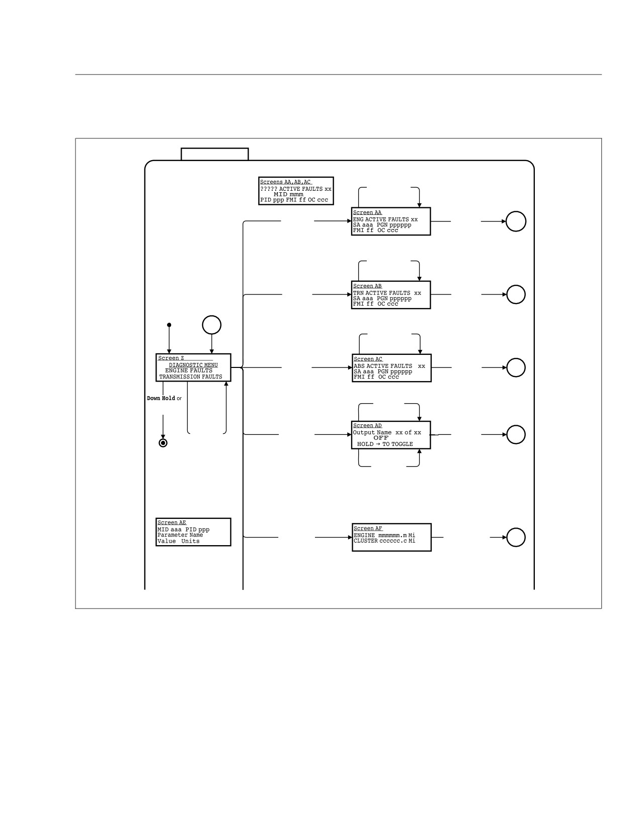
Propane Fuel System
Diagnostics
Screens AA,AB,AC Format For J1587
Down Press
Note 5:
Display Next Fault
Screen Z scrolls to display the
following items:
ENGINE FAULTS
TRANSMISSION FAULTS
Right Press
Right Press
ABS FAULTS
Engine Faults
Or
Menu
CHECK OUTPUTS
Highlighted
Down Hold
CHECK DATA INPUTS
ODOMETER DIAGNOSTICS
CHECK GAUGES
CHECK WARNING LAMPS
CHECK LCD
Down Press
CHECK BINARY INPUTS
Display Next Fault
CHECK ANALOG INPUTS
CHECK DATA LINK
VERSION INFORMATION
Right Press
Right Press
EXIT
Trans Faults
Or
Menu
The text DIAGNOSTIC MENU
Highlighted
Down Hold
remains fixed on the first line.
Menu
Down Press
Display Next Fault
Right Press
Right Press
ABS Faults
Or
Menu
Highlighted
Down Hold
Down Press
(Right & Exit
Change to
highlighted)
Next Output
Down Press
Highlight next
Right Press
Right Press
line of list.
Check Outputs
Or
Menu
At bottom,
Highlighted
Down Hold
wrap to top
Right Hold
Toggle Output
State Between
Off and On
Screen AE For J1587
Right Press
Odometer Diag
Right || Hold Down
Menu
Highlighted
09/23/2009
f040795
Fig. 17.6, Diagnostic Menu Screens, Screen 1
The instrument cluster has an emergency buzzer that
Warning and Indicator Lights
sounds when mission-critical conditions occur.
There are 19 warning and indicator lights (telltales)
A description of the standard warning and indicator
installed in the dash message center. See
lights are listed below.
Fig. 17.18. There are four rows of lights. Lights in-
stalled in the top row are optional and their positions
may vary. The lights in the bottom three rows are
installed in fixed positions on all vehicles. Most are
standard, but a few are optional.
17.10
Propane Fuel System
Other Text for Screen AG
Down Press
Change to
Next Gauge
Right Press
Check Gauges
Right || Hold Down
Menu
Highlighted
Right Hold
Step Gauge to
Next Position
Down Press
Change to
Next Telltale
Right Press
Warning Lamps
Right || Hold Down
Menu
Highlighted
Right Hold
Toggle State
Between
Off and On
Right Press
Right ||
Check LCD
9 Seconds Elapsed
Menu
Highlighted
|| Hold Down
Every 1.5 Seconds /
Invert Video of
Displayed Image
Down Press
Change to
Next Input
Right Press
Check Binary Inputs
Right || Hold Down
Menu
Highlighted
09/23/2009
f040796
Fig. 17.7, Diagnostic Menu Screens, Screen 2
• Transmission Prognostics Warning—if the
Maintenance Warning Light
transmission has prognostics enabled.
When the amber maintenance warning light illumi-
nates, the message display center will alert the driver
Left-Turn Signal Arrow
as follows:
The green left-turn signal arrow flashes on and off
• Oil Change Required—alerts the driver that the
whenever the outside left-turn signal lights are flash-
engine has reached the recommended oil
ing.
change interval.
Both turn signal arrows flash when the hazard warn-
• Air Filter Reminder—the air filter requires
ing flasher is turned on.
checking or replacement.
17.11
Propane Fuel System
Down Press
Change to
Next Input
Right Press
Screen AK
Check Analog Inputs
Input Name
Right || Hold Down
Menu
Pin pp of 26
Highlighted
xx.x Units
Down Press
Scroll Screen
Down 1 Line
Screen AL
Right Press
ECUs on Data Bus
Check Data Link
J1939 SA xx
Right || Hold Down
Menu
Highlighted
J1939 SA yy
Screen AM
Right Press
SOFTWARE VER: x.yy
Version Information
Right || Hold Down
Menu
CONFIG: ccccccc
Highlighted
HARDWARE VER: z
AUXILIARY
SCREENS
02/06/2012
f040797
Fig. 17.8, Diagnostic Menu Screens, Screen 3
bodily injury, property damage, or severe damage
Check Engine Indicator
to the engine.
The amber check engine indicator light illuminates
The red stop engine warning light illuminates to indi-
when certain faults are detected. If a critical engine
cate that the protection system available for the en-
condition exists (for example, low oil pressure or high
gine has been activated. The engine ECU will derate
coolant temperature), the check engine light will illu-
the engine, allowing it to run, but at lower rpm and
minate to alert the driver to correct the condition as
slower vehicle speed. The vehicle may be driven to a
soon as possible. If the condition gets worse, the
safe location.
stop engine light will illuminate.
NOTE: If the check engine light illuminates dur-
NOTICE
ing vehicle operation, take the vehicle directly to
an authorized Freightliner service facility.
Because operating the engine when the red stop
engine light is illuminated can lead to severe en-
Stop Engine Warning
gine damage, the driver must move the vehicle to
a safe location as quickly as possible and shut
down the engine.
WARNING
If the engine is shut down while the vehicle is in ser-
When the red STOP engine lamp illuminates, the
vice, a single restart attempt may be performed. De-
driver must immediately move the vehicle to a
pending on the nature of the fault condition, a cool-
safe location at the side of the road to prevent
down period may be required before restarting. If,
causing a hazardous situation that could cause
upon restarting, the fault condition still exists the
17.12
Propane Fuel System
Ignition On or
Headlamps On or
Marker Lamps On or
Park Brake Off
ACTIVE
Ignition Off &
( Headlamps On or
IGNITION
Marker Lamps On or
OFF
Park Brake Off )
Ignition On
Ignition
Ignition
On
Off
IGNITION ON
NORMAL MODE
SELF TEST
H*
Self Test
Enabled
DISPLAY
AUXILIARY
DOWNLOAD
MESSAGES
SCREENS
MODE
Right Hold
H*
Park Brake On
No Warnings Active or
Active Warning
All Warnings
Messages
USB Drive Present &
Acknowledged
Park Brake On &
Vehicle Speed = 0 &
Not in Self Test
WARNING
MESSAGES
Ignition Off &
Headlamps Off &
Marker Lamps Off &
Park Brake On
09/23/2009
f040788
Fig. 17.9, Ignition On, Normal Mode
lamp will come on and the engine should be shut
IMPORTANT: Do not attempt to restart the en-
down. At this point, the vehicle is unsafe to drive and
gine while the vehicle is moving. Bring the ve-
should be transported to an authorized Freightliner
hicle to a safe stop and restart the engine with
service facility.
the vehicle stopped.
17.13
Propane Fuel System
SELF TEST
The Self Test screens display the FCCC
logo in normal video (Screen A) and in
reverse video (Screen B)
Startup Screen Enabled
Screen A
XXXXXXXXXXXXXXXXXXXXXX
XXXXXXXXXXXXXXXXXXXXXX
XXXXXXXXXXXXXXXXXXXXXX
Screen Displayed
for 1.5 Seconds
Startup Screen Disabled
Screen B
XXXXXXXXXXXXXXXXXXXXXX
XXXXXXXXXXXXXXXXXXXXXX
XXXXXXXXXXXXXXXXXXXXXX
Screen Displayed
for 1.5 Seconds
DISPLAY
MESSAGES
02/06/2012
f040789
Fig. 17.10, Self Test
Malfunction Indicator Lamp (MIL)
Headlight High-Beam Indicator
Indicates an engine emissions-related fault. See the
The blue high-beam indicator light (sideways beam
engine operation manual for details.
icon) illuminates when the headlight high beams are
on.
Low Air Pressure Warning
Wait to Start Indicator
The red low air pressure warning light and emer-
gency buzzer activate when the engine is turned on
The amber wait to start indicator light illuminates with
if air pressure in the primary or secondary air reser-
the ignition switch in the ON position prior to engine
voir is below 65 to 75 psi (448 to 517 kPa), and re-
start-up. Do not crank the engine until the wait to
main on until air pressure rises above that level in
start indicator light goes out.
both reservoirs.
Hydraulic Brake System Warning
The warning light and buzzer also activate during
operation whenever air pressure in the primary or
The red brake system warning illuminates if there is
secondary air reservoir falls below 65 to 75 psi (448
a hydraulic brake system failure, or if the vehicle is
to 517 kPa).
powered and the engine is not running.
17.14
Propane Fuel System
DISPLAY MESSAGES
Right Hold
Reset Highlighted Item
Down Hold
(if resettable)
Make No Changes
Screen C
Screen D
Selected Line 1 Data
Right Press
Favorites Display Menu
Selected Line 2 Data
Highlight First Item in List
Average Fuel Economy
Selected Line 3 Data
Gear Attained Status
Right Press
Down Press
Down Press
Put Data For Highlighted Item
Move to, and Highlight,
Highlight CurrentLine
In Display Line CurrentLine
Next Item in List
HighlightTimer = 5 sec.
Right Hold
New Warning
Park Brake On
Message Active
HighlightTimer = 0
WARNING
AUXILIARY
MESSAGES
SCREENS
11/23/2011
f040790
Fig. 17.11, Display Messages
ABS Indicator
Check Transmission Indicator
The amber antilock brake system (ABS) indicator
NOTE: The LPG check transmission indicator
light illuminates when there is a malfunction in the
has a different icon (exclamation point), and illu-
vehicle ABS.
minates when the transmission fluid temperature
goes above a preset level.
NOTE: For more information about this light and
the ABS system, see Chapter 10.
The amber check transmission indicator illuminates
when the temperature of the transmission fluid goes
Traction Control Indicator
above the preset level set by the transmission manu-
facturer.
The amber traction control indicator illuminates when
the wheels lose traction.
For more information, see the transmission manufac-
turer’s manual provided with the vehicle.
Shift Inhibit Indicator
Stop Transmission Indicator
The amber shift inhibit indicator light illuminates
whenever all conditions for safe transmission shifting
The red warning light illuminates when the transmis-
have not been met.
sion control unit senses a malfunction.
17.15
Propane Fuel System
AUXILIARY SCREENS
Right Press
Setup
SETUP
highlighted
SETUP.
Right Press
Maintenance
MAINTENANCE
highlighted
Screen G
SETUP
MAINTENANCE
DIAGNOSTICS
Down Press
Right Press
Highlight next
Diagnostics
DIAGNOSTICS
line of list.
highlighted
At middle,
wrap to top
Down Hold
Right Press
Trip Data
TRIP DATA
highlighted
DISPLAY
MESSAGES
02/06/2012
f040791
Fig. 17.12, Auxiliary Screens
Right-Turn Signal Arrow
Fasten Seat Belts Warning
The green right-turn signal arrow flashes on and off
The red fasten seat belts warning light (seat belt
whenever the outside right-turn signal lights are
icon) illuminates for 15 seconds after the ignition
flashing.
switch is turned on.
Both turn signal arrows flash when the hazard warn-
Brake System Warning/Parking Brake
ing flasher is turned on.
On Indicator
The red brake system warning/parking brake on indi-
cator light (BRAKE legend) activates whenever the
parking brake is engaged.
17.16
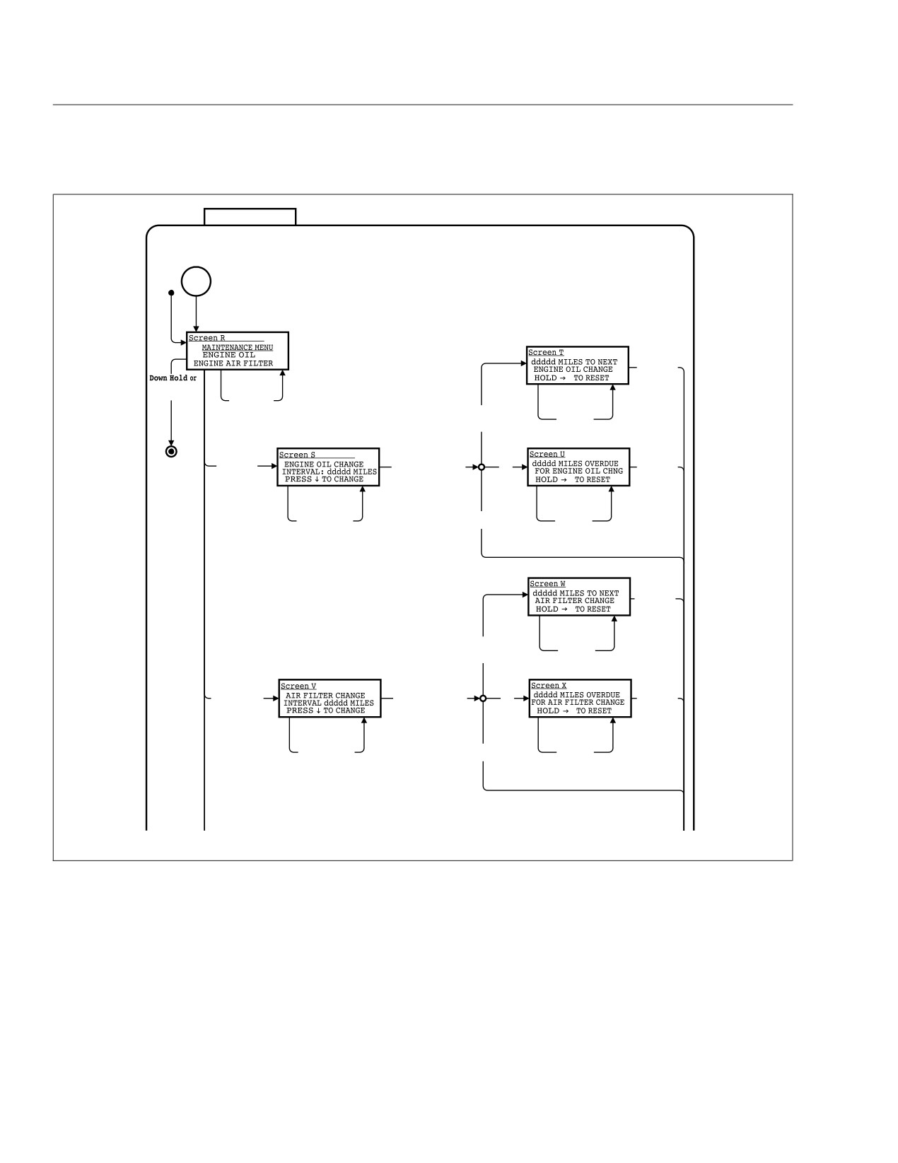
Propane Fuel System
MAINTENANCE
Maint
Menu
Right Press
Or
Down Hold
Down Press
(Right & Exit
Highlight next
highlighted)
line of list.
At middle,
Oil Change Baseline +
Right Hold
wrap to top
Oil Change Distance >=
Oil Change
Odometer
Baseline =
Odometer
Right Press
Right Press
Right Press
Engine Oil
Oil Change Distance =
else
Or
Highlighted
Current Displayed
Down Hold
Value
Down Press
Right Hold
Display Next
Oil Change
Oil Change
Value of Oil
Distance = 0
Baseline =
Change Distance
Odometer
Right Press
Or
Down Hold
Air Change Baseline +
Right Hold
Air Change Distance >=
Air Change
Odometer
Baseline =
Odometer
Right Press
Right Press
Right Press
Air Change Distance =
Engine Air Filter
else
Or
Current Displayed
Highlighted
Down Hold
Value
Down Press
Right Hold
Display Next
Air Change
Air Change
Value of Air
Distance = 0
Baseline =
Change Distance
Odometer
09/23/2009
f040793
Fig. 17.13, Maintenance Menu Screens, Screen 1
If the vehicle is moving at a speed of 2 mph (3 km/h)
Cruise Control Indicator
or more, the emergency buzzer will sound until the
parking brake is released.
A green indicator illuminates when the cruise control
is activated.
NOTE: The BRAKE legend is required in the
U.S. In Canada, the icon is required.
17.17
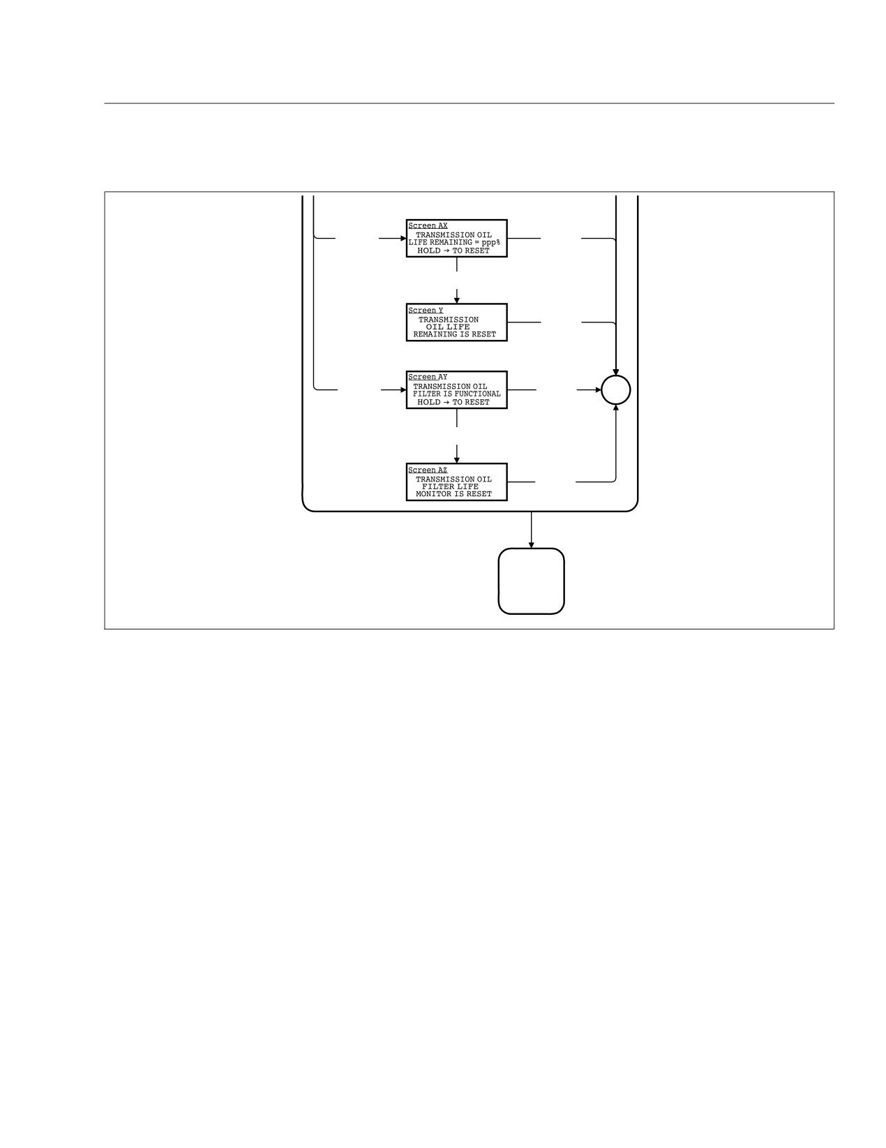
Propane Fuel System
Right Press
Right Press
Transmission
Or
Oil Life
Down Hold
Highlighted
Right Hold
Send SPN 1584 = 37
Right Press
Or
Down Hold
Right Press
Right Press
Transmission
Maint
Or
Oil Filter
Menu
Down Hold
Highlighted
Right Hold
Send SPN 1584 = 39
Right Press
Or
Down Hold
AUXILIARY
SCREENS
02/06/2012
f040794
Fig. 17.14, Maintenance Menu Screens, Screen 2
Emergency Buzzer
Speedometer and Tachometer
The emergency buzzer sounds during the ignition
Speedometer
sequence and whenever one of the following condi-
tions exists:
Three kinds of speedometer faces are available. The
U.S. version of the speedometer registers speed in
• The engine oil pressure falls below the preset
both miles per hour (mph) and kilometers per hour
level which is 6 psi (41 kPa) at 700 rpm, or 18
(km/h), with mph in larger numbers. See Fig. 17.19.
psi (124 kPa) at 4400 rpm.
The NAFTA version (not shown) of the speedometer
• The air pressure falls below the preset level,
face reverses this arrangement, with km/h in larger
which is 65 psi (448 kPa).
numbers. The metric-only version (not shown) shows
km/h exclusively.
• The parking brake is set with the vehicle mov-
ing at a speed greater than 2 mph (3 km/h).
Tachometer
• The coolant temperature rises above 253°F
(123°C) and the check engine and stop engine
The tachometer indicates engine speed in revolutions
lights illuminate. When the coolant temperature
per minute (rpm) and serves as a guide for shifting
falls below 244° (118°C) the emergency buzzer
the transmission and keeping the engine in the ap-
and stop engine light will turn off.
propriate rpm range. See Fig. 17.19.
NOTE: The check engine light will remain on
until the vehicle is inspected at an authorized
Freightliner service facility.
17.18
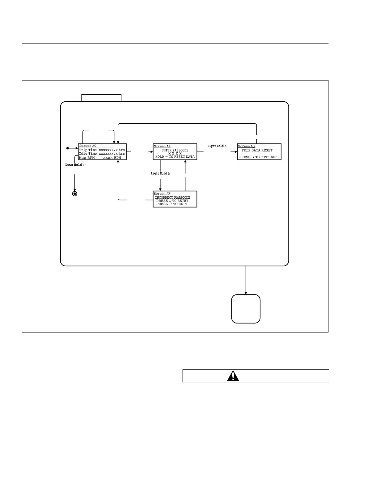
Propane Fuel System
Trip Data
Down Press
Highlight next
line of list.
At bottom,
wrap to top
Right Press
Right Press
Correct Passcode /
Reset All
Reset Trip
Highlighted
Data
(Right & Exit
highlighted)
Down Press
Wrong Passcode /
Note 6:
Screen AO scrolls to display
the following items:
Trip Time
Right Press
Idle Time
Max RPM
Avg RPM
Max Speed
Avg Speed
Avg Fuel Economy
Reset All
Exit
AUXILIARY
SCREENS
09/23/2009
f040798
Fig. 17.15, Trip Data
Standard Instruments
Primary and Secondary Air Pressure
Gauges
Fuel Level Gauge
The fuel level gauge indicates the level of fuel in the
WARNING
fuel tanks. See Fig. 17.20. A low-level warning light
illuminates when the diesel fuel level registers 1/8th
If air pressure falls below minimum pressure, the
of capacity.
braking ability of the vehicle will be limited. Slow
the vehicle down and bring it to a gradual stop.
Do not attempt to move the vehicle until air pres-
sure has risen above the minimum level. Moving
a vehicle without adequate braking power could
17.19
Propane Fuel System
WARNING MESSAGES
Msg Displayed for 5 Sec. /
/
Display Next Entry in
Display 1st Message
Warning Message List
in Warning
Message List
Screen AN
WARNING
Any Button Press
Warning Message
No Warning
Messages in List /
H*
DISPLAY
MESSAGES
02/06/2012
f040799
Fig. 17.16, Warning Messages
cause an accident resulting in personal injury or
the vehicle to a safe stop and investigate the
death.
cause to prevent further damage. Do not operate
the engine until the cause has been determined
Air pressure gauges register the pressure in the pri-
and corrected.
mary and secondary air systems. Normal pressure
with the engine running is 100 to 120 psi (690 to 827
During normal engine operation, the coolant tem-
kPa) in both systems. See Fig. 17.21.
perature gauge should read 200 to 205°F (93 to
96°C). See Fig. 17.22. If the temperature remains
Air pressure gauges are required on all vehicles with
below 160°F (71°C) or exceeds 235°F (113°C), in-
air brakes. A low-air-pressure warning light and
spect the cooling system to determine the cause.
buzzer, connected to both the primary and secondary
See the vehicle workshop manual for troubleshooting
systems, activate when air pressure in either system
and repair procedures.
drops below a minimum pressure of 65 to 75 psi
(448 to 517 kPa).
The coolant temperature gauge is very important.
See Fig. 17.22. If the coolant temperature rises
When the engine is started, the warning light and
above 253°F (123°C), the check engine and stop
buzzer remain on until air pressure in both systems
engine lights will illuminate, and the buzzer will
exceeds minimum pressure.
sound. At this point, the engine will derate and idle
speed will increase, to speed up the cooling fan and
Coolant Temperature Gauge
water pump to cool the engine.
NOTICE
Grade Brake
A sudden increase in coolant temperature may
IMPORTANT: The grade brake is an optional
indicate engine or cooling system failure. Bring
auxiliary brake system that works through the
17.20
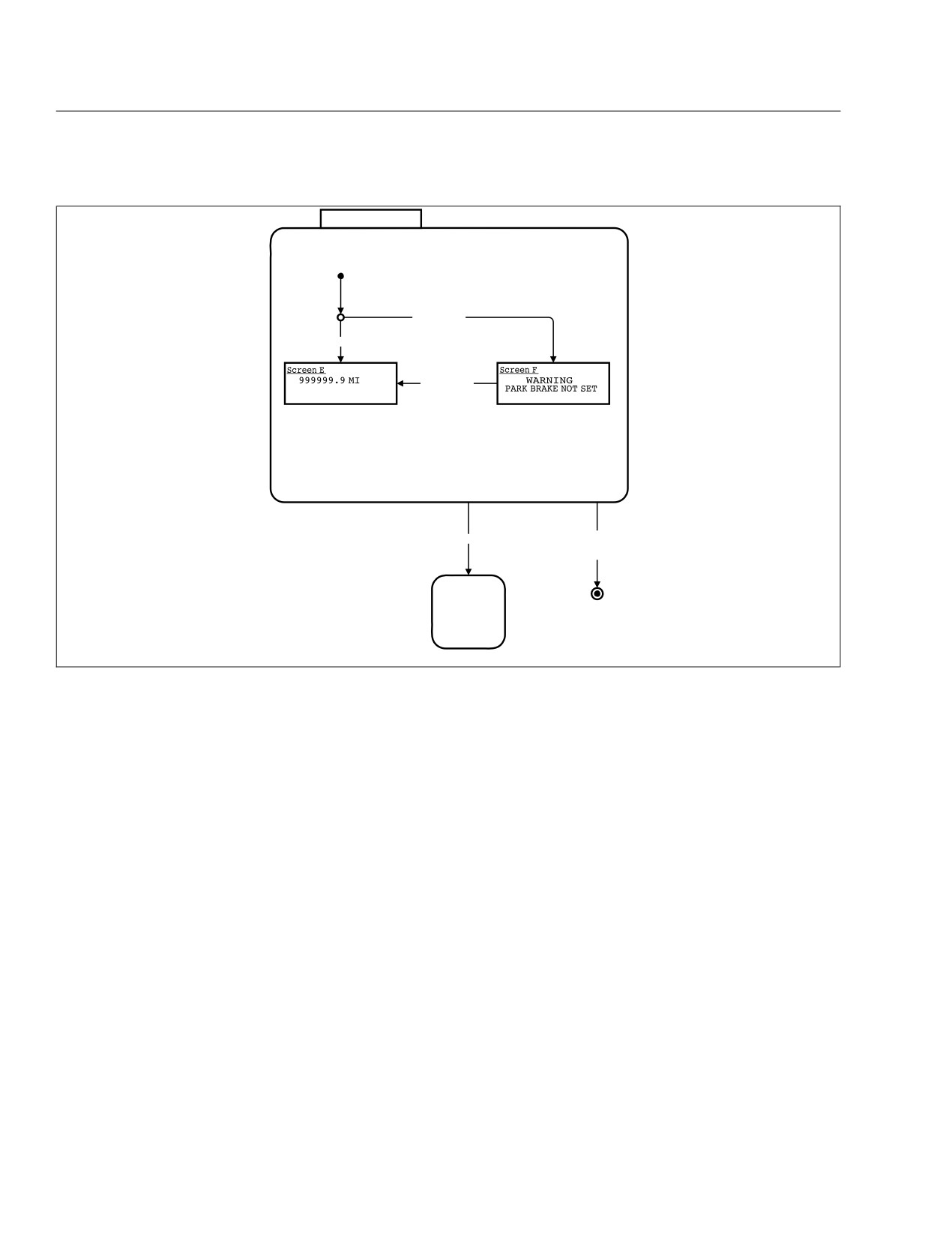
Propane Fuel System
IGNITION OFF
Park Brake Off
Park Brake On
Park Brake On
Ignition On
Headlamps Off &
Marker Lamps Off &
Park Brake On
IGNITION
ON
02/06/2012
f040800
Fig. 17.17, Ignition Off (shown when ignition is keyed OFF)
transmission. It should not be confused with ex-
haust brake or engine brake. Furthermore, the
grade brake should not be used in place of the
service brakes to stop the vehicle.
Chassis equipped with a propane engine may have
an optional grade brake. The grade brake is de-
signed to downshift the transmission—when going
downhill for example—without overspeeding the en-
gine. Refer to the Allison Operator’s Manual for
proper operation of the grade brake. See Fig. 17.23
for an example of the grade brake switch. An amber
light activates at the top of the switch when the
grade brake is activated.
17.21
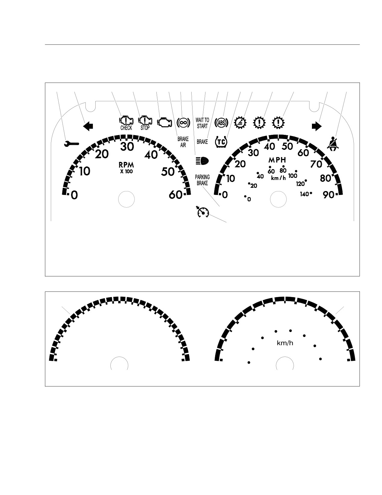
Propane Fuel System
1
2
3
4
5
6
7
8
9
10
11
12
13
14
15
16
17
18
10/30/2012
19
f611201
1. Maintenance Warning Light
8. Headlight High-Beam Indicator
14. Check Transmission Indicator
2. Left-Turn Signal Arrow
9. Wait to Start Warning
15. Stop Transmission Indicator
3. Check Engine Indicator
10. Hydraulic Brake System Warning
16. Right-Turn Signal Arrow
4. Stop Engine Warning
11. ABS Indicator
17. Fasten Seat Belt Warning
5. Malfunction Indicator Lamp (MIL)
12. Traction Control Indicator
18. Parking Brake On Indicator
6. Low Air Pressure Warning
13. Shift Inhibit Indicator
19. Cruise Control Indicator
7. Engine Brake Light (not used)
Fig. 17.18, LPG Engine Warning and Indicator Lights
1
2
30
40
50
30
60
20
40
MPH
RPM
20
70
X 100
60
80
10
50
40
100
10
80
120
20
140
0
60
0
90
0
09/18/2013
f611217
1. Tachometer
2. Speedometer
Fig. 17.19, Speedometer and Tachometer (U.S. version)
17.22
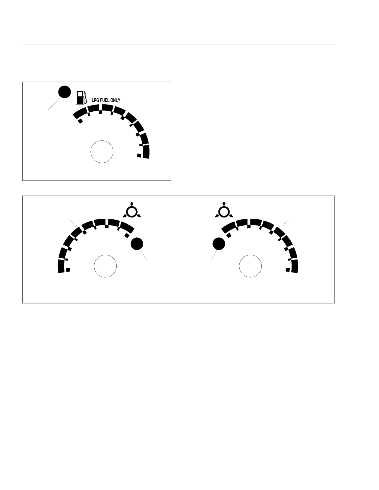
Propane Fuel System
1
F
1/2
E
10/01/2013
f611219
1. Low-Level Warning Light
Fig. 17.20, Fuel Level Gauge
PSI
P
S
PSI
1
4
75
75
150
150
2
3
0
0
09/18/2013
f611218
1. Primary Air Pressure Gauge
3. Low Secondary Air Pressure Warning Light
2. Low Primary Air Pressure Warning Light
4. Secondary Air Pressure Gauge
Fig. 17.21, Air Pressure Gauges
17.23
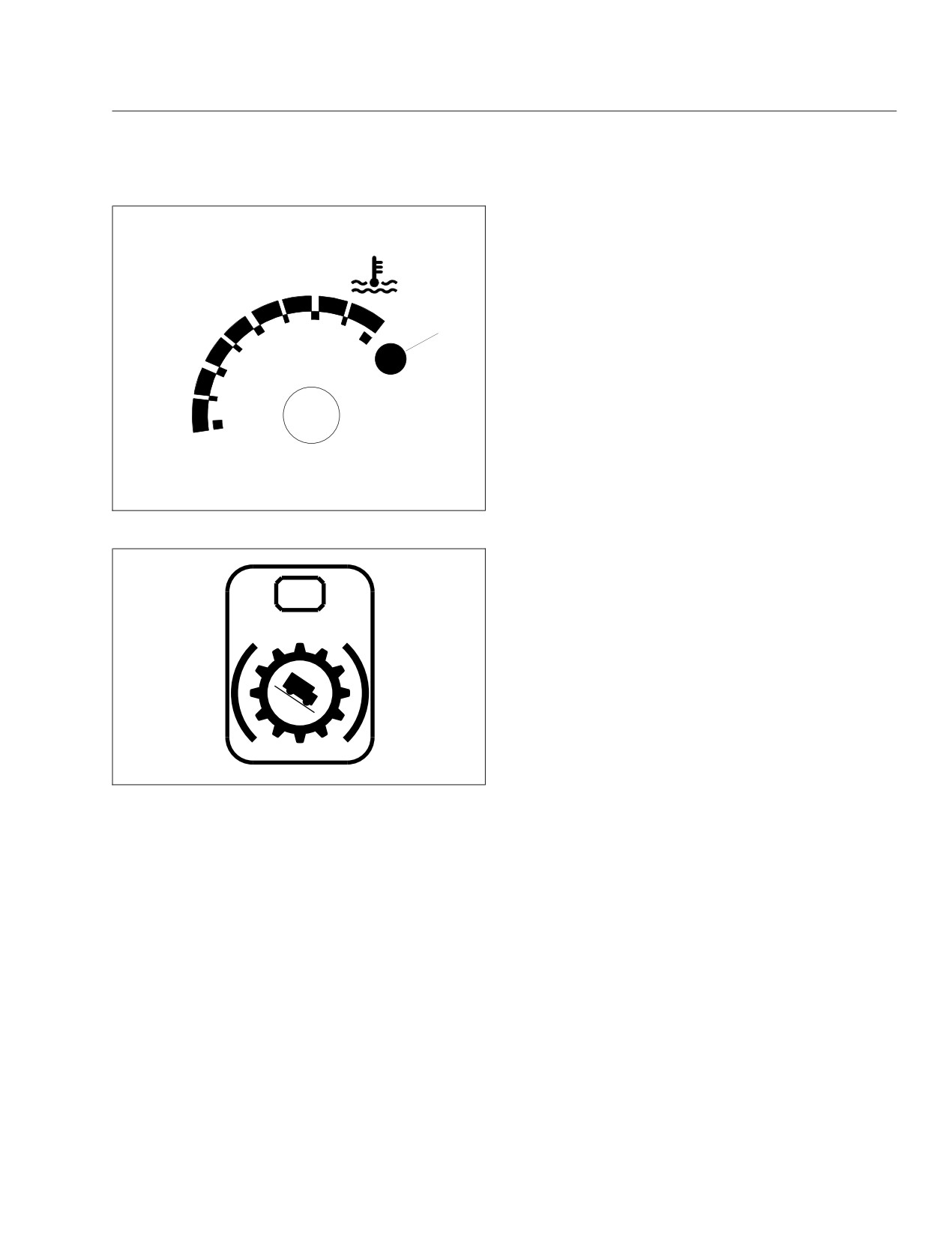
Propane Fuel System
1
H
C
09/18/2013
f611220
Fig. 17.22, Coolant Temperature Gauge
09/20/2013
f261458
Fig. 17.23, Grade Brake Switch
17.24

18
Specifications
Torque Charts
18.1
Conversion Charts
18.4
Fluid and Lubricant Specifications
18.5
Fuse Information
18.5
Replacement Light Bulbs
18.6
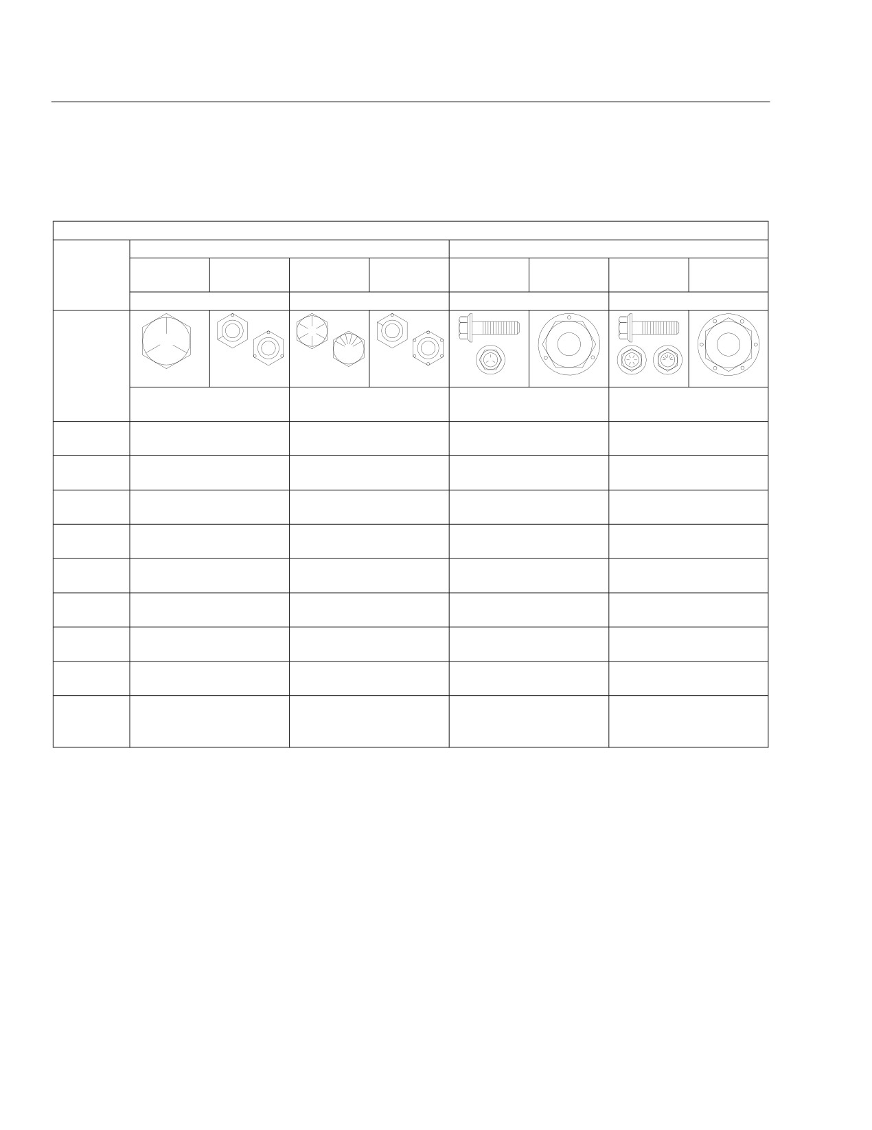
Specifications
Torque Charts
Torque Values for U.S. Customary Thread Fasteners With Lubricated* or Plated Threads†
Regular Hex
Flanged
Thread
Grade 5
Grade 5 or
Grade 8 or
Grade 8 or
Grade 5
Grade B
Grade 8 or
Grade G
Diameter—
Bolt
B Nut
8.2 Bolt
C Nut
Bolt
Nut
8.2 Bolt
Nut
Pitch
Torque: lbf·ft (N·m)
Torque: lbf·ft (N·m)
Torque: lbf·ft (N·m)
Torque: lbf·ft (N·m)
f230002
f230003
f230004
f230005
f230006
f230007
f230008
f230009
1/4-20
7
(9)
8
(11)
6
(8)
10
(14)
1/4-28
8
(11)
9
(12)
7
(9)
12
(16)
5/16-18
15
(20)
16
(22)
13
(18)
21
(28)
5/16-24
16
(22)
17
(23)
14
(19)
23
(31)
3/8-16
26
(35)
28
(38)
23
(31)
37
(50)
3/8-24
30
(41)
32
(43)
25
(34)
42
(57)
7/16-14
42
(57)
45
(61)
35
(47)
60
(81)
7/16-20
47
(64)
50
(68)
40
(54)
66
(89)
1/2-13
64
(87)
68
(92)
55
(75)
91
(123)
1/2-20
72
(98)
77
(104)
65
(88)
102
(138)
9/16-12
92
(125)
98
(133)
80
(108)
130
(176)
9/16-18
103
(140)
110
(149)
90
(122)
146
(198)
5/8-11
128
(173)
136
(184)
110
(149)
180
(244)
5/8-18
145
(197)
154
(209)
130
(176)
204
(277)
3/4-10
226
(306)
241
(327)
200
(271)
320
(434)
3/4-16
253
(343)
269
(365)
220
(298)
357
(484)
7/8-9
365
(495)
388
(526)
320
(434)
515
(698)
7/8-14
402
(545)
427
(579)
350
(475)
568
(770)
1-8
—
582
(789)
—
—
1-12
—
637
(863)
—
—
1-14
—
652
(884)
—
—
* FCCC recommends that all plated and unplated fasteners be coated with oil before installation.
†
Use these torque values if either the bolt or nut is lubricated or plated (zinc-phosphate conversion-coated, cadmium-plated, or waxed, Geomet 321XL
coated, or waxed).
Table 18.1, Torque Values for U.S. Customary Thread Fasteners With Lubricated or Plated Threads
18.1
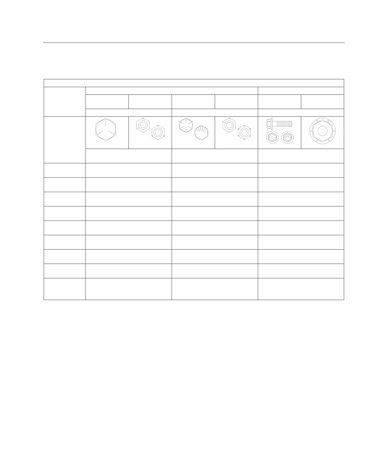
Specifications
Torque Values for U.S. Customary Thread Fasteners With Dry (Unlubricated)* Plain (Unplated) Threads†
Regular Hex
Flanged
Thread
Grade 5 or B
Grade 8 or 8.2
Grade 8 or C
Grade 8 or 8.2
Diameter—
Grade 5 Bolt
Grade G Nut
Nut
Bolt
Nut
Bolt
Pitch
Torque: lbf·ft (N·m)
Torque: lbf·ft (N·m)
Torque: lbf·ft (N·m)
f230002
f230003
f230004
f230005
f230008
f230009
1/4-20
8
(11)
10
(14)
—
1/4-28
9
(12)
12
(16)
—
5/16-18
15
(20)
22
(30)
22
(30)
5/16-24
17
(23)
25
(34)
—
3/8-16
28
(38)
40
(54)
40
(54)
3/8-24
31
(42)
45
(61)
—
7/16-14
45
(61)
65
(88)
65
(88)
7/16-20
50
(68)
70
(95)
—
1/2-13
70
(95)
95
(129)
95
(129)
1/2-20
75
(102)
110
(149)
—
9/16-12
100
(136)
140
(190)
140
(190)
9/16-18
110
(149)
155
(210)
—
5/8-11
135
(183)
190
(258)
190
(258)
5/8-18
155
(210)
215
(292)
—
3/4-10
240
(325)
340
(461)
340
(461)
3/4-16
270
(366)
380
(515)
—
7/8-9
385
(522)
540
(732)
—
7/8-14
425
(576)
600
(813)
—
1-8
580
(786)
820
(1112)
—
1-12
635
(861)
900
(1220)
—
1-14
650
(881)
915
(1241)
—
* Threads may have residual oil, but will be dry to the touch.
†
Male and female threads (bolt and nut) must both be unlubricated and unplated. If either is plated or lubricated, use Table 18.3. FCCC recommends that
all plated and unplated fasteners be coated with oil before installation.
Table 18.2, Torque Values for U.S. Customary Thread Fasteners With Dry (Unlubricated) Plain (Unplated) Threads
18.2
Specifications
Torque Values for Metric Thread Fasteners With Lubricated* or Plated Threads†
Thread
Class 8.8 Bolt
Class 8 Nut
Class
10.9 Bolt
Class 10 Nut
Diameter—
Pitch
Torque: lbf·ft (N·m)
Torque: lbf·ft (N·m)
8.8
8
10.9
10
f230010
f230011
f230012
f230013
M6
5
(7)
7
(9)
M8
12
(16)
17
(23)
M8 x 1
13
(18)
18
(24)
M10
24
(33)
34
(46)
M10 x 1.25
27
(37)
38
(52)
M12
42
(57)
60
(81)
M12 x 1.5
43
(58)
62
(84)
M14
66
(89)
95
(129)
M14 x 1.5
72
(98)
103
(140)
M16
103
(140)
148
(201)
M16 x 1.5
110
(149)
157
(213)
M18
147
(199)
203
(275)
M18 x 1.5
165
(224)
229
(310)
M20
208
(282)
288
(390)
M20 x 1.5
213
(313)
320
(434)
M22
283
(384)
392
(531)
M22 x 1.5
315
(427)
431
(584)
M24
360
(488)
498
(675)
M24 x 2
392
(531)
542
(735)
M27
527
(715)
729
(988)
M27 x 2
569
(771)
788
(1068)
M30
715
(969)
990
(1342)
M30 x 2
792
(1074)
1096
(1486)
* FCCC recommends that all plated and unplated fasteners be coated with oil before installation.
†
Use these torque values if either the bolt or nut is lubricated or plated (zinc-phosphate conversion-coated,
cadmium-plated, or waxed, Geomet 321XL coated, or waxed).
Table 18.3, Torque Values for Metric Thread Fasteners With Lubricated or Plated
Threads
18.3
Specifications
Conversion Charts
Metric/U.S. Customary Conversion
When You Know U.S.
Multiply
When You
Multiply
To Get Metric
To Get U.S. Customary
Customary
By
Know Metric
By
Length
inches (in)
25.4
millimeters (mm)
0.03937
inches (in)
inches (in)
2.54
centimeters (cm)
0.3937
inches (in)
feet (ft)
0.3048
meters (m)
3.281
feet (ft)
yards (yd)
0.9144
meters (m)
1.094
yards (yd)
miles (mi)
1.609
kilometers (km)
0.6215
miles (mi)
Area
square inches (in2)
645.16
square millimeters (mm2)
0.00155
square inches (in2)
square inches (in2)
6.452
square centimeters (cm2)
0.155
square inches (in2)
square feet (ft2)
0.0929
square meters (m2)
10.764
square feet (ft2)
Volume
cubic inches (in3)
16387.0
cubic millimeter (mm3)
0.000061
cubic inches (in3)
cubic inches (in3)
16.387
cubic centimeters (cm3)
0.06102
cubic inches (in3)
cubic inches (in3)
0.01639
liters (L)
61.024
cubic inches (in3)
fluid ounces (fl oz)
29.54
milliliters (mL)
0.03381
fluid ounces (fl oz)
pints (pt)
0.47318
liters (L)
2.1134
pints (pt)
quarts (qt)
0.94635
liters (L)
1.0567
quarts (qt)
gallons (gal)
3.7854
liters (L)
0.2642
gallons (gal)
cubic feet (ft3)
28.317
liters (L)
0.03531
cubic feet (ft3)
cubic feet (ft3)
0.02832
cubic meters (m3)
35.315
cubic feet (ft3)
Weight/Force
ounces (av) (oz)
28.35
grams (g)
0.03527
ounces (av) (oz)
pounds (av) (lb)
0.454
kilograms (kg)
2.205
pounds (av) (lb)
U.S. tons (t)
907.18
kilograms (kg)
0.001102
U.S. tons (t)
U.S. tons (t)
0.90718
metric tons (t)
1.1023
U.S. tons (t)
Torque/Work Force
inch-pounds (lbf·in)
11.298
Newton-centimeters (N·cm)
0.08851
inch-pounds (lbf·in)
foot-pounds (lbf·ft)
1.3558
Newton-meters (N·m)
0.7376
foot-pounds (lbf·ft)
Pressure/Vacuum
inches of mercury (inHg)
3.37685
kilo Pascals (kPa)
0.29613
inches of mercury (inHg)
pounds per square inch (psi)
6.895
kilo Pascals (kPa)
0.14503
pounds per square inch (psi)
Table
18.4, Metric/U.S. Customary Conversion
Temperature Conversion
Then
When You Multiply
Then
When You Know
Subtract
To Get
To Get
Divide By
Know
By
Add
degrees Fahrenheit (°F)
32
1.8
degrees Celsius (°C)
1.8
32
degrees Fahrenheit (°F)
Table 18.5, Temperature Conversion
18.4

Specifications
Fluid and Lubricant
Specifications
See Table 18.6 for fluid and lubricant specifications.
Fluid and Lubricant Specifications
Component
Recommended Fluid or Lubricant
Front Axle Spindle Pins, Tie Rods, Drag Link,
Multipurpose Grease Lithium 12- Hydroxy Stearate NLGI No.
2; for
Intermediate Steering Shaft, Front Brake and
temperatures below 0°F (-18°C), use MIL-G-10924B
Pedal Shafts, Slip Spline and Universal Joints
Hydraulic Brake Master Cylinder
Heavy-Duty DOT 3 Brake Fluid
Brake and Pedal Pivots
Starplex 2 (lithium soap-based grease)
Engine
See Manufacturer’s Recommendations
Transmission
Mobil Delvac Synthetic ATF
Fuel
Ultralow-Sulfur Diesel Fuel
HD5 Grade Propane
Disc Brake Caliper Rails
FCCC No. 4JD623 Brake Caliper Slide Grease
Rear Axle Differential
See Manufacturer’s Recommendations
Hydraulic System Reservoir
ATF must meet Dexron® III or TES-389 specifications
Engine Coolant
50% Water/50% Ethylene Glycol Antifreeze
Chevron Delo Antifreeze No. 275110 (propane engines only)
Table 18.6, Fluid and Lubricant Specifications
Fuse Information
Main PDM Fuse Identification
CAV
Description
Fuse
See Table 18.7 for descriptions of a typical set of
F17
Chassis Module
30A
fuses. Fuse identification varies with options.
F18
Bulkhead Module
30A
F19
Chassis Module
30A
Main PDM Fuse Identification
F20
Bulkhead Module
30A
CAV
Description
Fuse
F21
Expansion Module 2
30A
F1
VCU (spare)
10A (—)
F22
Bulkhead Module
30A
F2
Blower Motor
30A
F23
Expansion Module 2
30A
F3
Engine ECU
20A
F24
Hydraulic Pump and RLY (spare)
25A (—)
F4
RR Wall HTR RLY LO/HI
30A
F25
Adjustable Pedals
10A
F5
Ignition Switch
10A
F26
Chassis Module
30A
F6
Hydromax RLY (spare)
30A (—)
F27
Heater Booster Pump
20A
F7
Stepwell HTR RLY LO/HI
30A
F28
Bulkhead Module
30A
F8
ICU3-M2
10A
F29
Crossing Arm RLY
10A
F9
Transmission ECU
10A
F10
Expansion Module 1
30A
Table 18.7, Main PDM Fuse Identification
F11
Expansion Module 1
30A
F12
Radio/Diagnostic
20A
F13
Expansion Module 1
30A
F14
Expansion Module 2
30A
F15
Bulkhead Module
30A
F16
ABS ECU
15A
18.5

Specifications
Replacement Light Bulbs
See Table 18.8 for a listing of replacement light
bulbs.
Replacement Light Bulbs
Lamp Trade
Light Location
Number
Warning Panel Lights
53 or LB-0108
Headlights MB and XB;
2A1
High Beam
1A1
Low Beam
2B1
Gauge Illumination
53, 194 or LB-0107
Automatic Transmission Gear
53
Selector
Table 18.8, Replacement Light Bulbs
18.6

Index
Subject
Page
Subject
Page
Parking Brake Control Valve
5.11
A
Bus Amenities
3.8
Adjusting Headlight Aim
15.1
Storage
3.8
Aftertreatment System (ATS)
Regen Switch
5.5
C
Aftertreatment System, EPA10
and Newer Engines
8.1
Canadian Motor Vehicle Safety
ATS Warning Lamps
8.2
Standard Labels
1.2
DPF Maintenance
8.3
Care of Chrome Parts
13.1
Parked Regen
8.2
Care of Fiberglass Parts
13.1
Principles of Operation
8.1
Changing a Flat Tire
14.6
Air Brake Operation
10.1
Checking Headlight Aim
15.1
Caging the Parking Brakes
10.2
Conversion Charts
18.4
Operating the Brakes
10.2
Parking Brake Interlock,
D
Optional
10.1
Allison On-Highway
Daily Pretrip Inspection and
Transmissions
9.1
Maintenance Checklist
11.2
Operating Instructions, 2000
Daily Pretrip Inspection and
Series Transmissions
9.2
Maintenance Procedures
12.1
Operating Instructions, 3000
Dashboard and Instrument
Series
9.3
Panel Care
13.1
Range Inhibit Indicator, 2000
Diesel Exhaust Fluid and Tank,
Series
9.2
EPA10 and Newer Engines
8.3
Safety Precautions
9.1
DEF Tank
8.4
Ametek Instrument Panel
17.5
DEF Warnings and Engine
Menu Navigation
17.9
Limits
8.4
Menu System
17.6
Diesel Exhaust Fluid
8.3
Message Display Center
17.5
Fuel/DEF Gauge
8.4
Priority Messages
17.5
Disabling the Hybrid Electric
Self-Test
17.6
Vehicle (HEV) System
16.4
Assist Rails and Access Steps
2.1
Option 1 (preferred method)
16.4
Folding Steps
2.1
Option 2
16.5
Automatic Tire Chain Control
5.5
Option 3
16.5
Braking and Stopping
5.6
Drive Axles, Detroit™ and
Meritor™
9.6
Engaging/Disengaging the
Tire Chains
5.5
Drive Axles With Differential
Lock
9.6
Use of the Tire Chains While
They Are Engaged
5.6
Driver Switch Panel Controls
5.4
Driving Precautions
9.1
Dual Air Brake System
10.1
B
Emergency Braking System
10.1
Battery Access
2.2
Parking Brakes
10.1
Battery Compartment
2.2
Primary Air Brake System
10.1
Battery Disconnect Switch,
Secondary Air Brake System
10.1
Optional
2.2
Bosch Hydraulic Pin Slide
E
Brakes
10.3
General Information
10.3
Eaton Automated Transmission
16.3
Operation
10.3
1
(Low Gear)
16.4
Braking Controls
5.11
D (Drive)
16.4
Meritor™ WABCO® Antilock
H (Hold)
16.4
Braking System (ABS)
5.11
N (Neutral)
16.4
I-1

Index
Subject
Page
Subject
Page
P (Park)
16.3
F
R (Reverse)
16.3
Federal Motor Vehicle Safety
Electrical System General
Standard Labels
1.1
Information
6.1
Fire Extinguisher
14.1
Emergency Door
2.4
Floor Cleaning
13.2
Rear Emergency Door
2.4
Fluid and Lubricant
Using the Main Entry/Exit
Specifications
18.5
Door in an Emergency
2.5
Front Door Opening and
Emergency Exits
14.4
Closing
2.2
Emergency Door
14.4
Buses with Exterior Door
Emergency Roof Escape
Control
2.2
Hatches
14.5
Buses without Exterior Door
Emergency Window Exits
14.5
Control
2.2
Using the Main Entry/Exit
Fuse Information
18.5
Door in an Emergency
14.4
Emergency Kit
14.1
Emergency Roof Escape Hatch
2.4
G
Emergency Starting With
General Information
17.1
Jumper Cables
14.1
Body Heater Loop Valve
17.1
Emergency Window Exits
2.5
Grade Brake
17.20
Vehicles Built Since January
9, 2008
2.5
Emissions Labels
1.2
H
Aftertreatment System
Hazard Warning Lights
14.1
Indicators Label
1.3
Heater/Air Conditioner/Defrost
EPA Noise Emission Control
Control Panel
5.11
Label
1.2
Air Conditioning
5.15
Vehicle Emission Control
Information Label
1.3
Air Selection Switch
5.12
Engine Operation
17.2
Booster Pump
5.15
Engine Shutdown
17.3
Climate Control Panel
5.12
Engine Starting
17.2
Defrosting
5.15
General Information
17.2
Fan Switch
5.12
High Idle Options
7.3
Fresh Air Mode
5.14
Engine Shutdown
7.4
Passenger Heater Switch
5.12
Engine Starting and Shutdown
16.2
Recirculation Mode
5.14
Engine Shutdown
16.3
Temperature Control Switch
5.14
Starting
16.2
Hood Opening and Closing
2.3
The Cranking System
16.2
Closing the Hood
2.4
Engine Starting
7.1
Tilting the Hood
2.3
General Information
7.1
Horn Control
5.7
Starting After Extended
Hybrid Electric Vehicle (HEV)
Shutdown or Oil Change
7.1
Overview
16.1
Entering and Exiting the Bus
2.1
Cooling System
16.2
Entering the Bus
2.1
High-Voltage Safety
Features
16.1
Exiting the Bus
2.1
Hill Start Aid
16.1
Stepwell Light
2.1
Regenerative Braking
16.1
Exhaust Brake
10.5
Hybrid Electric Vehicle (HEV)
Driving Downhill
10.6
System Fault Lamps
16.4
General Information
10.5
Operating Characteristics
10.6
Shutting Down the Engine
10.7
Starting the Engine
10.6
I-2

Index
Subject
Page
Subject
Page
I
O
Ignition Switch and Key
5.1
Optional Instruments
4.10
In Case of an Emergency
16.5
Air Intake Restriction Gauge
4.10
Emergency Shutdown
16.5
Ammeter
4.11
In Case of an Accident or
Axle Oil Temperature Gauge,
Fire
16.5
Rear
4.11
Instrumentation Control Unit
4.1
Digital Clock
4.11
Dash Message Center
4.1
Engine Oil Temperature
Ignition Sequence
4.2
Gauge
4.12
Mode/Reset Switch
4.4
Pyrometer
4.12
Odometer
4.4
Transmission Fluid
Temperature Gauge
4.13
Turbocharger Boost
J
Pressure Gauge
4.13
Jumpstarting
16.6
P
L
Power Distribution Modules
6.1
Powertrain Controls
5.8
Lighting Controls
5.1
Axle Switches
5.9
Footwell Light
5.2
Cruise Control Switch
5.8
Headlight/Parking Light
Switch
5.1
Exhaust Brake Switch
5.9
Interior Dome Lights
5.2
Fast Idle System
5.9
Panel Light Increase/
Transmission Controls
5.9
Decrease Switch
5.2
Preliminary Checks
15.1
Pretrip and Post-Trip Inspection
General Information
11.1
M
Propane Refueling
17.3
Meritor Cam-Master® Q Plus
Brakes
10.3
R
Cam-Master Q Plus
Operation
10.3
Replacement Light Bulbs
18.6
Meritor WABCO® Pneumatic
Running Out of Fuel
14.5
Antilock Braking System
(ABS)
10.3
Automatic Slack Adjusters
10.5
S
Automatic Traction Control
10.4
Safety Precautions
16.2
Pneumatic ABS Operation
10.4
Seat Belts and Tether Belts
3.6
Mirrors
3.1
General Information
3.6
Mirror Heat Switch, Optional
3.1
Seat Belt Inspection
3.7
Power Mirrors, Optional
3.1
Seat Belt Operation
3.7
Monthly Post-Trip Inspection
Seats
3.2
and Maintenance Checklist
11.3
Bench Seats
3.3
Monthly Post-Trip Inspection
Bostrom Seat
3.4
and Maintenance Procedures
12.11
General Information
3.2
Multifunction Turn Signal Switch
5.2
National 2000 Series Seat
3.4
Hazard Warning Lights
5.4
Sears Seat
3.5
Headlight High Beams
5.3
Track-Mounted Seats
3.3
Turn Signal Lever
5.2
Speedometer and Tachometer
4.8
Windshield Wiper/Washer
Controls
5.3
Speedometer
4.8
Tachometer
4.8
Standard Instruments
4.8
I-3

Index
Subject
Page
Subject
Page
Coolant Temperature Gauge
4.8
High Exhaust System
Engine Oil Pressure Gauge
4.8
Temperature (HEST) Lamp
4.6
Fuel Level Gauge
17.19
Hydraulic Brake System
Warning
17.14
Fuel/Diesel Exhaust Fluid
(DEF) Gauge
4.9
Left-Turn Signal Arrow
4.6
Primary and Secondary Air
Low Air Pressure Warning
4.7
Pressure Gauges
4.9
Low Battery Voltage Warning
4.6
Voltmeter
4.10
Low Oil Pressure Warning
4.6
Steering Controls
5.7
Maintenance Warning Light
17.11
Malfunction Indicator Lamp
(MIL)
4.5
T
Optional Indicator Lights
4.7
Tire and Rim Information
1.2
Right-Turn Signal Arrow
4.7
Torque Charts
18.1
Shift Inhibit Indicator
17.15
Towing
16.6
Stop Engine Warning
4.5
Front Towing Hookup
14.4
Stop Transmission Indicator
17.15
Traction Control Indicator
17.15
Transmission Overheat
V
Indicator
4.5
Vehicle Certification Plate and
Wait to Start Indicator
17.14
Data Plate
1.1
Water In Fuel Indicator
4.6
Vehicle Loading
1.2
Washing and Polishing
13.1
Vinyl Upholstery Cleaning
13.1
Weekly Post-Trip Inspection
Ball Point Ink
13.2
and Maintenance Checklist
11.3
Chewing Gum
13.2
Weekly Post-Trip Inspection
Miscellaneous
13.2
and Maintenance Procedures
12.9
Nail Polish and Nail Polish
Windows
3.1
Remover
13.2
Driver’s Window
3.1
Ordinary Dirt
13.2
Passenger Windows
3.1
Paint and Shoe Heel Marks
13.2
Windshield Washer Reservoir
3.9
Shoe Polish
13.2
Sulfide Stains
13.2
Tars, Asphalts, and Creosote
13.2
W
Warning and Indicator Lights
4.4
ABS Indicator
4.5
Brake System Warning/
Parking Brake On Indicator
4.6
Check Engine Indicator
4.4
Check Transmission
Indicator
17.15
Cruise Control Indicator
4.7
Diesel Particulate Filter
(DPF) Lamp
4.6
Emergency Buzzer
4.7
Fasten Seat Belts Warning
4.6
Headlight High-Beam
Indicator
4.7
High Coolant Temperature
Warning
4.6
I-4