Robinson R22 Helicopter. MAINTENANCE MANUAL (2018) - page 1
R22 MAINTENANCE MANUAL
AND INSTRUCTIONS FOR CONTINUED AIRWORTHINESS
RTR 060 VOLUME I
Production Certificate Number 424WE
Type Certificate Number H10WE
Robinson Helicopter Company
Phone:
(310) 539-0508
2901 Airport Drive
Fax:
(310) 539-5198
Torrance, California 90505-6115
Web:
United States of America
OFFICE HOURS
Monday through Friday, 7:30 a.m. to 4:30 p.m., Pacific Time.
Lunch hour is 11:30 a.m. to 12:30 p.m.
HOLIDAYS
CUSTOMER SUPPORT AND SPARES ORDERS
Procure parts from any R22 Dealer or Service Center,
or order directly from RHC Customer Service via email, fax, or phone.
PUBLICATIONS
OCT 2018
Introduction
Page i
SUBSCRIPTION ORDER AND RENEWAL FORMS
Subscription order and renewal forms are located at www.robinsonheli.com.
WARRANTY INFORMATION
Helicopter and parts warranty information is located at www.robinsonheli.com.
Page ii
Introduction
OCT 2018
CHAPTER LIST
Introduction
Chapter 1
General
Chapter 2
Inspection
Chapter 3
Life-Limited Components
Chapter 4
Airframe
Chapter 5
Landing Gear
Chapter 6
Powerplant
Chapter 7
Drive Train
Chapter 8
Flight Controls
Chapter 9
Rotor Systems
Chapter 10
Rigging, Track and Balance
Chapter 11
Environment Control
Chapter 12
Fuel System
Chapter 13
Instruments
Chapter 14
Electrical and Avionics Systems
Chapter 15
Furnishings
Chapter 16
Dimensions and Descriptions
Chapter 17
Jacking and Hoisting
Chapter 18
Weight and Balance
Chapter 19
Ground Handling
Chapter 20
Parking and Storage
Chapter 21
Placards and Markings
Chapter 22
Servicing
Chapter 23
Standard Practices
Chapter 24
Lights
Chapter 25
Doors and Windows
Chapter 26
Main Rotor
Chapter 27
Main Rotor Drive System
Chapter 28
Tail Rotor
Chapter 29
Tail Rotor Drive System
Chapter 30
Engine Controls
Chapter 31
Engine Oil System
Chapter 32
Police Version
Chapter 33
Electrical System
Chapter 34
Avionics
Chapter 35
Wiring Diagrams
Chapter 36
Special Tools
Chapter 37
Revision Log
OCT 2018
Introduction
Page iii
Intentionally Blank
Page iv
Introduction
OCT 2018
TECHNICAL PUBLICATIONS
RECOMMENDED CHANGE REPORT
Please direct recommended changes to RHC Technical Publications via the email address
listed below, by phone, or by submitting a duplicate of this completed form by fax or mail.
Please include or have available the information detailed in this form.
Recommended changes may include but are not limited to general comments, corrections,
omitted information, or clarification of instructions.
Please send recommendations to:
Email: techpubs@robinsonheli.com
Robinson Helicopter Company
Phone: (310) 539-0508
Attention: Technical Publications
Fax:
(310) 539-5198
2901 Airport Drive
Torrance, CA 90505-6115
United States of America
Date:
Publication:
Name:
Chapter:
Company:
Section:
Helicopter Model:
Page:
Serial Number:
Revision:
Phone:
Email:
COMMENTS:
OCT 2018
Introduction
Page v
Intentionally Blank
Page vi
Introduction
OCT 2018
CHAPTER 1
GENERAL
Section Title
Page
1.000
Introduction
1.1
1.001
R22 Maintenance Manual Revisions
1.1
1.002
R22 Maintenance Authorization
1.2
1.003
R22 Component Maintenance Authorization
1.2
1.004
Maintenance Record
1.2
1.005
Notations
1.3
1.006
Maintenance Manual and Illustrated Parts Catalog References
1.3
1.007
Definitions and Abbreviations
1.4
1.008
Service Information
1.6
1.009
Assembly Instructions for R22-series Helicopter Crated for Export
1.7
1.100
Helicopter Servicing
1.11
1.101
Scheduled Maintenance and Inspections
1.11
1.102
Additional Component Maintenance
1.12
OCT 2018
Chapter 1 General
Page 1.i
Intentionally Blank
Page 1.ii
Chapter 1 General
OCT 2018
CHAPTER 1
GENERAL
1.000 Introduction
The R22 Maintenance Manual contains instructions necessary for proper maintenance,
servicing, and handling of R22-series helicopters. The R22 Instructions for Continued
Airworthiness (ICA) includes the R22 Maintenance Manual (MM), R22 Illustrated Parts
Catalog (IPC), R22 Service Bulletins (SBs), R22 Service Letters (SLs), Lycoming O-320-
series and O-360-series Operator’s Manuals, applicable Lycoming technical publications,
and applicable component manufacturer technical publications.
Service Bulletins are issued by Robinson Helicopter Company (RHC), Lycoming, and
component manufacturers. RHC Service Bulletin compliance is mandatory; comply with
other applicable Service Bulletins as directed. RHC technical publications are available online
at www.robinsonheli.com. Recent technical publications are available from Lycoming at
aero.
Kit instructions are issued for field installation of either optional or mandatory (due to
Service Bulletin or parts obsolescence) equipment upgrades, or provisions for upgrades.
Kit instruction issued by RHC either implement approved type design data, or are approved
as type design data.
CAUTION
Always read instructions completely before performing a task.
1.001 R22 Maintenance Manual Revisions
Before using the R22 Maintenance Manual, verify it consists of current effective pages.
The list of effective pages is located in the Revision Log in Chapter 37. When a new
manual is purchased, complete and submit the Subscription Order Form available online at
www.robinsonheli.com. Subscribers receive publication revisions for a two-year period.
Renew subscriptions annually. The revision status for all RHC technical publications is
available online at www.robinsonheli.com.
OCT 2018
Chapter 1 General
Page 1.1
1.002 R22 Maintenance Authorization
Only appropriately certificated mechanics who have successfully completed an R22
factory-sponsored maintenance course, or are under direct supervision of the above-stated
mechanic, may perform maintenance, repairs, or inspections on R22-series helicopters.
Annual inspections of U.S.-registered light helicopters must be performed by holders of
an Inspection Authorization (IA) or by repair stations certificated by the Federal Aviation
Administration (FAA). The daily preflight and some preventive maintenance may be
performed by the above-stated mechanics, or by the pilot/owner after receiving appropriate
instruction in accordance with the R22 Pilot’s Operating Handbook and applicable aviation
regulations.
1.003 R22 Component Maintenance Authorization
Only appropriately certificated mechanics who have successfully completed both a factory-
sponsored maintenance course and component maintenance course, and who possess
technical data supplied by RHC, are authorized to perform maintenance specified in the
Component Maintenance Manual (CMM). Component maintenance may only be performed
at an RHC-authorized Service Center that has required special tools.
1.004 Maintenance Record
The Airframe Maintenance Record is available online at www.robinsonheli.com.
Airframe Maintenance Record blank PDF forms may be used for R22-series, R44-series, and
R66-series helicopters. Component Record blank PDF forms may be used for life-limited
or TBO components. Blank paper copies are available for purchase (P/N R8478 Airframe
Maintenance Record and P/N R8479 Component Record [pack of 20]).
A Component Record is a maintenance record of the removals, installations, or maintenance
performed on a life-limited or TBO component. When a life-limited or TBO component is
installed in the helicopter, the Component Record card is inserted in the Airframe Maintenance
Record. When a life-limited or TBO component is removed from the helicopter, remove the
Component Record card and keep the card with the Component. Major assemblies may
contain one or more life-limited or TBO component.
RHC encourages operators to utilize Component Record cards to assist in tracking time on
interchangeable parts since service lives may be different between models.
RHC does not create Component Record cards for spares, however, operators may create
their own.
RHCs Repair Station does not require a Component Record card in order to perform work
on a component, unlike a Component/Return Authorization form.
RHC recommends using a toner-based laser, or a pigment-based inkjet, color printer and 65
lb white (96 bright) premium card stock for Maintenance Record or Component Record card
production. Maintenance Record binders and tab sets are available separately (P/N R8656
Maintenance Record Binder and P/N R8650 Maintenance Record Tabs).
Page 1.2
Chapter 1 General
OCT 2018
1.005 Notations
The following notations will be found throughout the manual:
NOTE
A NOTE provides emphasis or supplementary explanation.
CAUTION
Equipment damage can result if a CAUTION is not followed.
WARNING
Personal injury or death can result if a WARNING is not followed.
1.006 Maintenance Manual and Illustrated Parts Catalog References
Maintenance Manual and Illustrated Parts Catalog Section and Figure references are subject
to relocation and renumeration. Effort will be made at the time of RHC technical document
revisions to correct superseded references, however, certain documents may not otherwise
require revision and superseded references may remain. A keyword or part number search
in online documents (Ctrl+F [PC] or Command+F [Mac]) may help to locate applicable data.
OCT 2018
Chapter 1 General
Page 1.3
1.007 Definitions and Abbreviations
Refer to R22 Pilot's Operating Handbook (POH) Section 1 for additional definitions and
abbreviations.
A. Definitions
14 CFR § 27.602
A part identified as a 14 CFR § 27.602 critical part within this
Critical Part:
manual is subject to special inspection requirements. RHC
Technical Support must be notified whenever the part fails to meet
the special inspection requirements.
12 years:
With respect to a 12 year inspection or life-limit, 12 years means 12
years from the date of the factory-issued airworthiness certificate
or factory-issued authorized release certificate (FAA Form 8130-3,
Airworthiness Approval Tag).
Annually:
With respect to an annual inspection, annually means within the
preceding 12 calendar months.
Datum:
An imaginary vertical plane from which all horizontal measurements
are taken for balance purposes with the aircraft in level flight
attitude. Refer to § 16-20 for R22 datum location.
Empty Weight:
Empty Weight includes the weight of the airframe, powerplant,
required and installed equipment, fixed ballast, unusable fuel,
and gearbox oil. Refer to R22-series Type Certificate Data Sheet
(TCDS) in Chapter 3. Refer to Equipment List/Weight and Balance
Data Sheet (RF 134) and Weight and Balance Record in R22 POH
Section 6 for installed equipment.
Life-Limited Part:
Refer to Chapter 3. Any part for which a mandatory replacement
limit is specified in the type design, the Instructions for Continued
Airworthiness, or the maintenance manual.
Time in Service:
With respect to maintenance time records, time in service means
the time from the moment an aircraft leaves the surface of the
earth until it touches it at the next point of landing.
Page 1.4
Chapter 1 General
OCT 2018
1.007 Definitions and Abbreviations (continued)
B. Abbreviations
14 CFR:
Title 14 of the Code of Federal Regulations. The Federal Aviation
Regulations (FARs) are part of the CFR.
AOG:
Aircraft on Ground
ATA-100:
Air Transport Association of America Specification No. 100
BL:
Butt Line Station locations
CO:
Carbon Monoxide
CRA:
Component Return/Authorization
ELT:
Emergency Locator Transmitter
FS:
Fuselage Station locations
HID:
High Intensity Discharge
HS:
Horizontal Stabilizer Station locations
LBL:
Left Butt Line Station locations
LED:
Light Emitting Diode
LH:
Left-hand
LRU:
Line-Replaceable Unit
MRDS:
Main Rotor Drive Shaft
MRGB:
Main Rotor Gearbox
OEM:
Original Equipment Manufacturer
R22 IPC:
R22 Illustrated Parts Catalog
R22 MM:
R22 Maintenance Manual
R22 POH:
R22 Pilot’s Operating Handbook
RHC:
Robinson Helicopter Company
RH:
Right-hand
RS:
Rotor Station locations
SB:
Service Bulletin
SL:
Service Letter
TBO:
Time Between Overhaul
TCDS:
Type Certificate Data Sheet
TRDS:
Tail Rotor Drive Shaft
TRGB:
Tail Rotor Gearbox
TS:
Tailcone Station locations
TSN:
Time Since New
TSO:
Time Since Overhaul
WL:
Water Line Station locations
OCT 2018
Chapter 1 General
Page 1.5
1.008 Service Information
A. Part Designation
RHC parts are designated with an alphanumeric part number beginning with letter “A”,
“B”, “C”, etc., followed by three digits and a dash number.
A revision letter or letters follow(s) the stamped or ink-marked part number. Revision
progression is A thru Z, followed by AA thru AZ, followed by BA thru BZ, etc. Unless
otherwise specified, any revision of the same part number is interchangeable, such as
“A101-1 A” and “A101-1 D”.
A change in dash number indicates a change in form, fit, and/or function (e.g. part
number C339-1 is not interchangeable with part number C339-10 even though both
are jackshaft weldments for [hydraulic] R44s).
B. Returning Parts
All parts shipped to RHC must include a signed Component Return/Authorization (CRA)
Form available online at www.robinsonheli.com.
C. Ordering and Shipping
Procure parts from any R22 Dealer or Service Center, or order directly from assigned
RHC Customer Service Representative via email, fax, or phone.
D. Warranty Claims
Complete CRA Form (refer to Part B) and, in the Warranty Claim section, indicate if
rotorcraft or component is under warranty. If claim is for parts or for labor allowance
due to a Service Bulletin issued against rotorcraft or component, write in “per SB-XX”
adjacent to requested warranty action.
E. Customer Support Directory
Page 1.6
Chapter 1 General
OCT 2018
1.009 Assembly Instructions for R22-series Helicopter Crated for Export
NOTE
Aircraft assembly to be performed by a certificated mechanic.
1.
Remove all components from tailcone crate and all accessible components from cabin
crate. Assemble landing gear per §§ 5.220 (float gear only) and 5.320.
CAUTION
Do not lift helicopter and attached crate using main rotor hub;
damage to main rotor gearbox and frames could result.
2.
Attach a hoist to main rotor hub per § 17-20. Lift aft end of crate while taking up slack
in hoist. When main rotor shaft is vertical, remove bolts at landing gear attach points
and remove crate. Install landing gear per § 5.120. Lower helicopter on ground.
3.
Install front cross tube cover panel. For float landing gear, set float pressure per Mariner
supplement of Pilot’s Operating Handbook and verify float stabilizer is being used in
place of tail skid.
4.
Install tailcone per § 4.312. Install tail rotor visual warning guard.
5.
Install empennage assembly per § 4.322.
6.
Install exhaust system per § 6.520. Install lower half of cooling fan scroll.
7.
Remove preservative plugs from engine cylinder upper spark plug holes. Install upper
spark plugs and special torque per § 23-33. Connect ignition leads.
8.
Fill engine oil to six quart mark on dipstick, as required.
9.
Install main rotor blades per § 26-10. Match color coded markings on blades, hub bolts,
hub, and pitch links. Attach upper end of pitch links to pitch horns.
10.
Install tail rotor per §§ 9.212 or 9.213, as applicable.
11.
If required, fill battery with electrolyte and charge.
12.
Fill main and tail rotor gearboxes with A257-2 oil. For helicopters shipped “on-side”,
inject 6 ounces A257-2 oil into aft vent hole atop main rotor gearbox static mast tube.
13.
Fuel helicopter and drain a small amount of fuel through gascolator.
OCT 2018
Chapter 1 General
Page 1.7
1.009 Assembly Instructions for R22-series Helicopter Crated for Export (continued)
14.
If ship is equipped with artificial horizon, directional gyro, or vertical card magnetic
compass, install as follows:
Artificial Horizon and/or Directional Gyro:
a. Remove amber ALT light and red OIL light from B050 console. Pull out A777-1,
A981-1, or B197-1 instrument face by removing perimeter mounting screws.
Place a pad under face to prevent scratches.
b. Install required instrument(s) using screws provided.
CAUTION
Directional gyro mounting screws must not exceed 1 inch in
length or unit will be damaged.
c. Connect straight multi-pin connector to directional gyro and/or angled connector
to artificial horizon ensuring that angled strain relief points down. Ensure that
connectors lock in place. Ty-rap excess wiring.
d. Install instrument face, ALT light, and OIL light.
Vertical Card Magnetic Compass:
Locate two wires extending from windshield bow. Slide one piece of heat-shrink
tubing (provided) over each wire. Connect compass pins to wire sockets (polarity
not critical). Position heat-shrink tubing over connections and apply heat. Install
compass using two screws provided.
15.
Install battery (Negative Ground System).
NOTE
This must be performed by a qualified pilot and a certificated
mechanic.
16.
Perform preflight inspection per Pilot’s Operating Handbook and inspection per §§ 2.205
and 2.210.
17.
Check tail rotor balance per § 10.240.
18.
Perform hover checks in § 2.220.1. DO NOT proceed into forward flight at this time.
19.
Track and balance main rotor per § 10.230.
20.
While climbing at takeoff power per placard and 50 KIAS:
a. Evaluate roughness at maximum and minimum power-on RPM.
b. At minimum power-on RPM perform 30° left yaw to check for adequate directional
control.
Page 1.8
Chapter 1 General
OCT 2018
1.009 Assembly Instructions for R22-series Helicopter Crated for Export (continued)
21. During level flight at 3000 feet pressure altitude (if able), MCP, with right trim and
governor on:
a. Verify longitudinal and lateral cyclic control forces are neutralized (no tendency of
cyclic to creep longitudinally or laterally).
b. Verify collective control forces are neutralized (no tendency of collective to creep
up or down).
c. Verify throttle correlation. Set MAP to 22 inches and turn governor off. Without
twisting throttle, lower collective to 12 inches MAP then raise it to 22.5 inches
MAP. RPM must stay in green arc.
22. Evaluate roughness at minimum power-on RPM, takeoff power per placard, and Vne per
placard.
23. Check all instruments, gauges, and avionics for proper operation.
24. During autorotation at 50 KIAS and 90% rotor RPM, perform 30° right yaw to check
for adequate directional control.
OCT 2018
Chapter 1 General
Page 1.9
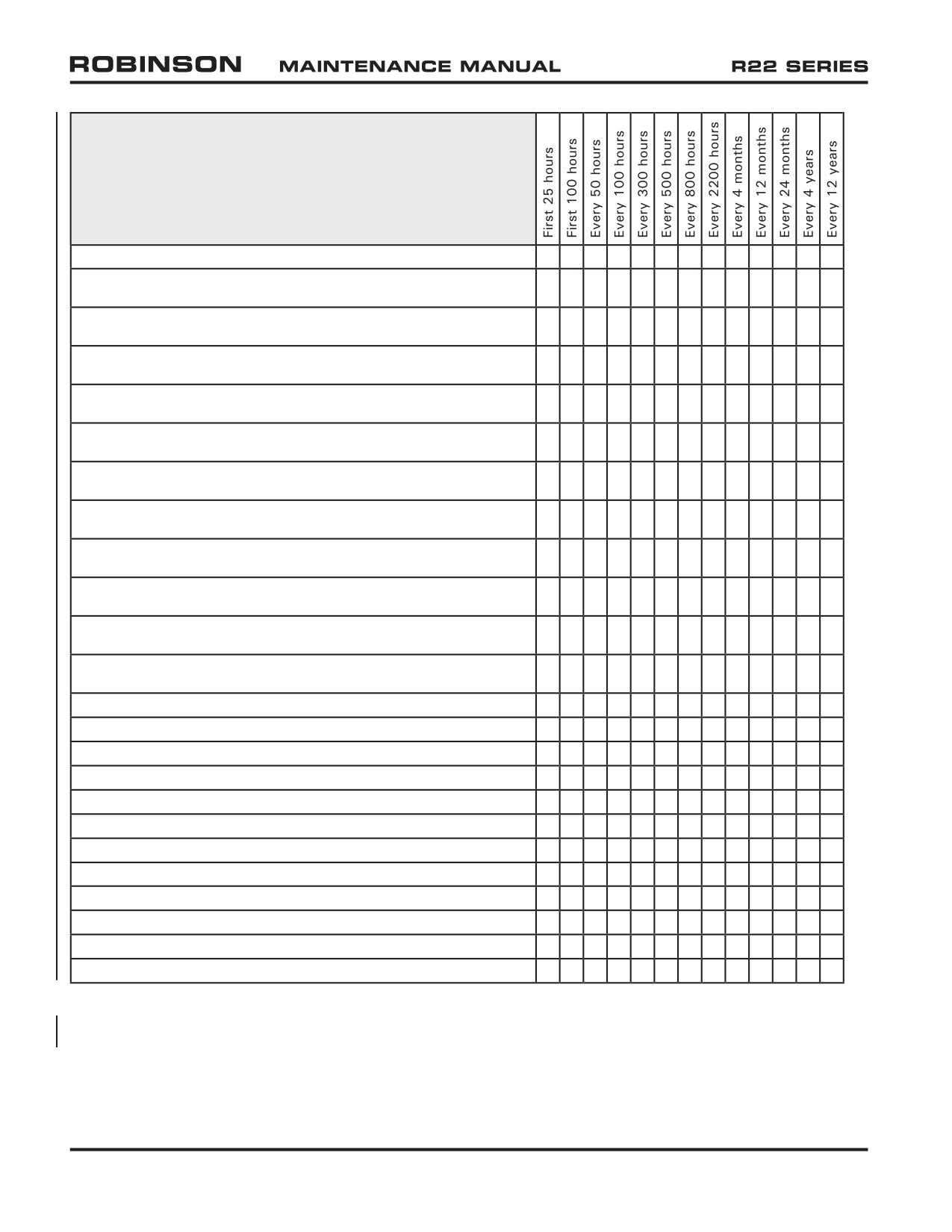
TABLE 1 SCHEDULED INSPECTIONS
Consult latest revision of listed
publications for specific applicability.
Perform inspection per Lycoming Operator’s Manual.*
•
•
•
•
Perform Lycoming SI 1129
•
•
Methods of Checking DC Alternator and Generator Belt Tension.
Perform Lycoming SI 1191
•
Cylinder Compression.
Perform Lycoming SI 1080
•
•
Maintenance Items for Special Attention.
Perform Lycoming SB 301*
•
Maintenance Procedures and Service Limitations for Valves.
Perform Lycoming SB 366, as applicable
•
Carburetor Throttle Body Screw Inspection.
Perform Lycoming SB 388 (also applies to replacement cylinders)
•
•
Procedure to Determine Exhaust Valve and Guide Condition.
Perform Lycoming SB 480
•
•
•
I. Oil & Filter Change & Screen Cleaning / II. Oil Filter/Screen Content Inspection.
Perform CMI SB 643, as applicable
•
•
•
•
Maintenance Intervals for All CMI/TCM/Bendix Magnetos & Related Equipment.
Perform CMI SB 658
•
•
Distributor Gear Maintenance.
Perform CMI SB 663
•
•
Two-Wire Magneto Tach. Breaker Contact (Points) Assy. P/N 10-400507.
Perform CMI SB 670
•
•
Replacement and maintenance of Magneto Distributor Block.
Perform 100-hour/annual inspection per § 2.400.
•
•
Lubricate A181-4 Revision K, L, and M bearings per § 22-42.
•
•
Lubricate A181-4 Revision N bearing per § 22-42.
•
•
Lubricate A184 bearing per § 22-41.
•
•
Perform clutch assembly lubricant inspection & servicing per § 22-30.
•
Drain and flush gearboxes per §§ 22-13 & 22-23.
•
Clean gearbox chip detectors per §§ 22-11 & 22-21.
•
•
Perform FAA AD 88-26-01 R2 (A158-1 spindles only).
•
Perform 2200-hour inspection per § 2.600.
•
Inspect emergency locator transmitter (ELT) per U.S. 14 CFR § 91.207.
•
Test and inspect transponder per U.S. 14 CFR § 91.413.
•
Perform 12-year inspection per § 2.600.**
•
* Shorter interval than published on referenced document.
** 12-year inspection is only required for helicopters that have accumulated 12 years in service and less than 2200 hours
time in service since new, since last 2200-hour inspection, or since last 12-year inspection.
Page 1.10
Chapter 1 General
OCT 2018
1.100 Helicopter Servicing
1.101 Scheduled Maintenance and Inspections
Required maintenance and inspection intervals are given in Table 1. Publications listed
are subject to revision.
Consult the following for specific applicability, as some aircraft may require maintenance
and inspections in addition to the requirements in Table 1:
● Aircraft maintenance records
● Service Bulletins (SBs)
● Aviation regulations
● Airworthiness Limitations
● Airworthiness Directives (ADs)
Preventive maintenance is required between scheduled inspections. Fluid leaks,
discoloration, fretting, galling, chafing, nicks, scratches, dents, cracks, and corrosion all
warrant further investigation. Unairworthy items must be replaced or repaired as allowed
by RHC.
OCT 2018
Chapter 1 General
Page 1.11
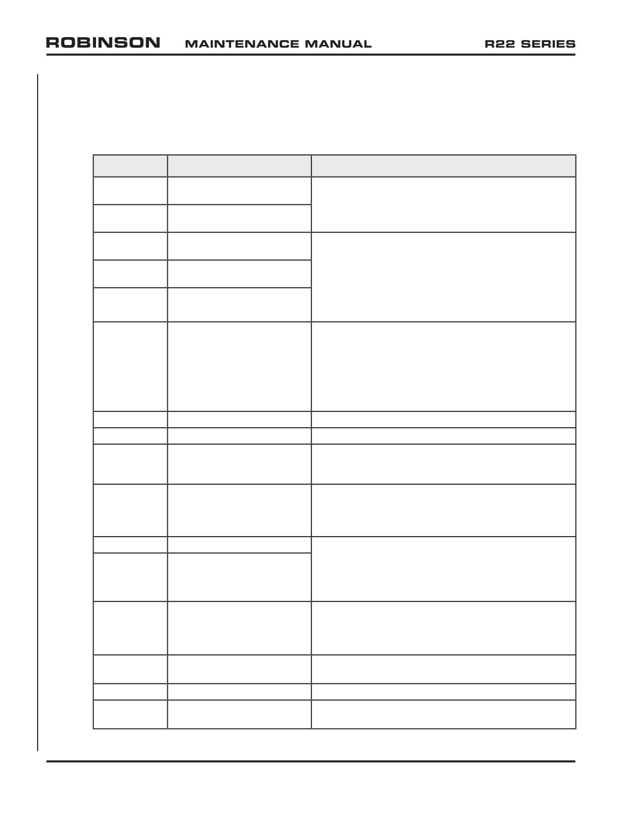
1.102 Additional Component Maintenance
A. Remove the following components when they have accumulated 12 years time in
service and less than 2200 hours time in service since new, since last overhaul, or
since last 12-year maintenance:
Part Number
Description
Action
A005-4
A154-1 Main Rotor Hub &
Perform inspection and repair per MM § 2.610, return
Bearing Assembly
to RHC for inspection and repair, or replace with new.
A005-12
B370-1 Main Rotor Hub &
Bearing Assembly
A005-6
A016-4 Main Rotor Blade &
Submit to RHC-authorized component maintenance
A158-1 Spindle Assembly
facility for
12-year maintenance, or replace with
new or overhaul exchange.
12-year maintenance
A005-7
A016-6 Main Rotor Blade &
includes blade replacement (as required), spindle
A158-1 Spindle Assembly
bearing replacement (as required), pitch horn screw
A005-14
A016-6 Main Rotor Blade &
replacement, boot and o-ring replacement, and
A158-3 Spindle Assembly
inspection.
A006-1 & -6
Main Rotor Gearbox
Submit to RHC-authorized component maintenance
Assembly
facility for 12-year maintenance, or replace with new
or overhaul exchange. 12-year maintenance includes
pinion seal replacement, o-ring replacement, sealed
bearing replacement, rubber mount replacement,
additional bearings replacement (as required), and
inspection.
A007-3 or -5
Fanshaft Assembly
Replace with new A007-5 fanshaft assembly.
A008-2 or -4
Tail Rotor Assembly
Replace with new A008-4 tail rotor assembly.
A014-8
Landing Gear Assembly
Replace with new.
originally installed on R22
S/N 0002 thru 0487.
A017-2
Swashplate Assembly
Submit to RHC-authorized component maintenance
facility for 12-year maintenance, or replace with new
or overhaul exchange. 12-year maintenance includes
inspection and repair as necessary.
A018-1
Clutch Assembly (anodized)
Submit to RHC-authorized component maintenance
facility for 12-year maintenance, or replace with new
A018-2
Clutch Assembly
or overhaul exchange. 12-year maintenance includes
(metalized)
seal and o-ring replacement, bearing replacement, and
inspection.
A020-2
Upper Frame Assembly S/N
Replace with new. Note: Frame replacement may
0399 and prior (originally
require tailcone forward bay replacement.
installed on R22 S/N 0002
thru 0311).
A021-1
Tail Rotor Gearbox
Replace with new or overhaul exchange B021-1 tail
Assembly
rotor gearbox assembly.
A031-1
Tail Rotor Pitch Control
Replace with new.
A041-11 or
Tail Rotor Drive Shaft
Replace with new A041-11 or -12 damper bearing as-
-12
Damper Bearing Assembly
sembly or replace with new B224-1 or -3 drive shaft.
Page 1.12
Chapter 1 General
OCT 2018
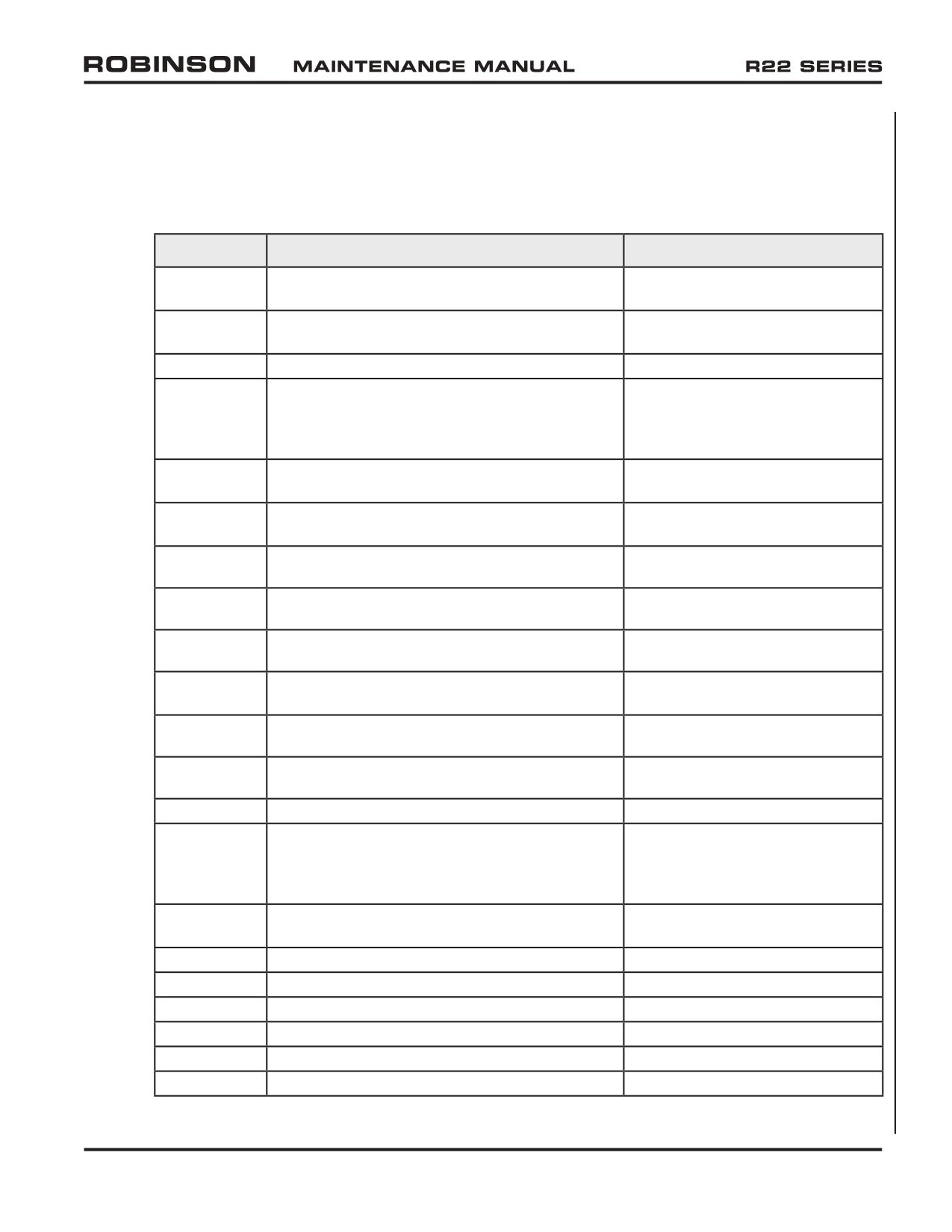
1.102 Additional Component Maintenance (continued)
A. Remove the following components when they have accumulated 12 years time in
service and less than 2200 hours time in service since new, since last overhaul, or
since last 12-year maintenance (continued):
Part Number
Description
Action
A044-1
Horizontal Stabilizer Rev M and prior (originally
Replace with new.
installed on R22 S/N 0002 thru 0631).
A051-1 or
Clutch Actuator Assembly (A051-1 includes
Replace with new or overhaul
A051-3
gearmotor assembly)
exchange.
A120-1
Tail Rotor Bellcrank
Replace with new.
A169-1, -2,
Muffler with Risers Rev J and prior (baffled
Replace with new.
or -4
muffler with straight tailpipe, originally
installed on R22 S/N 0002 thru 0500) with
subsequent revision.
A169-6 or
Muffler with Risers (O-320 engine)
Visually inspect muffler interior;
-35
verify no obvious loss of material.
A169-24 or
Muffler with Risers (O-360 engine)
Visually inspect muffler interior;
-37
verify no obvious loss of material.
A190-1 or -2
V-Belt Set
Replace with new A190-2 v-belt
set.
A193-2
Flex Plate
Replace with new A947-2 flex
plate assembly.
A193-3
Flex Plate
Replace with new A947-3 flex
plate assembly.
A197-1 thru
Tail Rotor Drive Shaft Assembly originally
Replace with B224-1 drive shaft &
-7
installed on R22 S/N 0002 thru 0747.
appropriate B223 yoke.
A258-1
Main Rotor Pitch Link Assemblies
Replace with new A258-1 or
A258-5 link assembly.
A258-5
Main Rotor Pitch Link Assemblies
Disassemble. 10X visually inspect
barrel; verify no corrosion.
A480-1
Swashplate Boot
Replace with new.
A493-1
Lower Sheave Rev H and prior (anodized,
Replace with new.
originally installed on R22 S/N 0002 thru
0294) with subsequent (steel-sprayed)
revision.
A649-1, -2,
Oil Cooler
Replace with new or overhaul
or C649-1
exchange C649-1 oil cooler.
A785-1
Hose - Air (intake)
Replace with new.
A785-2
Hose - Air (hot air inlet)
Replace with new.
A785-6
Hose - Air (engine cooling)
Replace with new.
A785-7
Hose - Air (alternator cooling)
Replace with new.
A785-26
Hose - Air (hot air inlet)
Replace with new.
A785-32
Hose
Replace with new.
OCT 2018
Chapter 1 General
Page 1.13
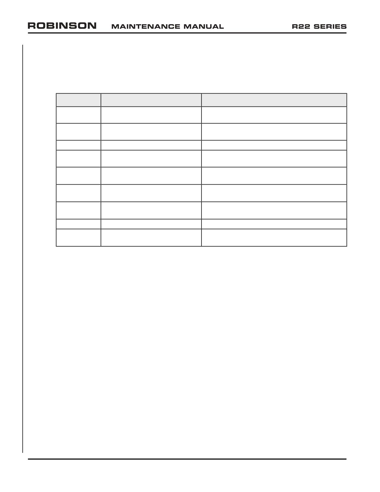
1.102 Additional Component Maintenance (continued)
A. Remove the following components when they have accumulated 12 years time in
service and less than 2200 hours time in service since new, since last overhaul, or
since last 12-year maintenance (continued):
Part Number
Description
Action
A792-2 or -4
Dual Tachometer
Replace with new or overhaul exchange A792-4
dual tachometer.
B021-1
Tail Rotor Gearbox Assembly
Perform 12-year maintenance per MM § 2.620,
or replace with new or overhaul exchange.
B173-1
V-belt - Alternator
Replace with new.
B174-1
Fanwheel (Rev “J” or
Perform 12-year maintenance per MM § 2.630,
subsequent)
or replace with new or overhaul exchange.
B283-1
Hose Assembly (fuel system)
Replace with new.
Revision A thru P
B283-2
Hose Assembly (fuel system)
Replace with new.
Revision A thru P
B283-6
Hose Assembly (fuel system)
Replace with new.
Revision A thru P
B286-2
Governor Controller
Replace with new or overhaul exchange.
D756-2 (or
Bellcrank Assembly - Throttle
Replace with new.
A011-2)
Page 1.14
Chapter 1 General
OCT 2018
1.102 Additional Component Maintenance (continued)
B. Remove the following components when they have accumulated 2200 hours time in
service since new or since last overhaul:
Part Number
Description
Action
A005-4
A154-1 Main Rotor Hub & Bearing
Perform inspection and repair per MM
§
Assembly
2.610, return to RHC for inspection and
repair, or replace with new.
A005-12
B370-1 Main Rotor Hub & Bearing
Assembly
A005-6
A016-4 Main Rotor Blade & A158-1
Replace with new or overhaul exchange
Spindle Assembly
A005-7 or A005-14 main rotor blade and
spindle assembly.
A005-7
A016-6 Main Rotor Blade & A158-1
Spindle Assembly
A005-14
A016-6 Main Rotor Blade & A158-3
Spindle Assembly
A006-1 & -6
Main Rotor Gearbox Assembly
Replace with new or overhaul exchange
A006-6 main rotor gearbox assembly.
A007-3 or -5
Fanshaft Assembly
Replace with new A007-5 fanshaft assembly.
A008-2 or -4
Tail Rotor Assembly
Replace with new A008-4 tail rotor assembly.
A014-8
Landing Gear Assembly originally
Replace with new.
installed on R22 S/N 0002 thru
0487.
A017-2
Swashplate Assembly
Submit to RHC-authorized component
maintenance facility for overhaul, or replace
with new or overhaul exchange.
A018-1
Clutch Assembly (anodized sheave)
Replace with new or overhaul exchange.
A018-2
Clutch Assembly (metalized sheave)
A020-2
Upper Frame Assembly S/N 0399
Replace with new. Note: Frame replacement
and prior (originally installed on R22
may require tailcone forward bay replacement.
S/N 0002 thru 0311).
A021-1
Tail Rotor Gearbox Assembly
Replace with new or overhaul exchange
B021-1 tail rotor gearbox assembly.
A031-1
Tail Rotor Pitch Control
Replace with new.
A041-11 or
Tail Rotor Drive Shaft Damper
Replace with new A041-11 or -12 damper
-12
Bearing Assembly
bearing assembly or replace with new B224-1
or -3 drive shaft.
A044-1
Horizontal Stabilizer Rev M and
Replace with new.
prior (originally installed on R22 S/N
0002 thru 0631).
A051-1 or
Clutch Actuator Assembly (A051-1
Replace with new or overhaul exchange.
A051-3
includes gearmotor assembly)
A120-1
Tail Rotor Bellcrank
Replace with new.
A121-17
Push-Pull Tube Assembly
Replace with new.
OCT 2018
Chapter 1 General
Page 1.15
1.102 Additional Component Maintenance (continued)
B. Remove the following components when they have accumulated 2200 hours time in
service since new or since last overhaul (continued):
Part Number
Description
Action
A169-1, -2,
Muffler with Risers Rev J and
Replace with new.
or -4
prior (baffled muffler with straight
tailpipe, originally installed on R22
S/N 0002 thru 0500).
A169-6 or
Muffler with Risers (O-320 engine)
Replace with new A169-35 muffler.
-35
A169-24 or
Muffler with Risers (O-360 engine)
Replace with new A169-37 muffler.
-37
A189-10
Nut - Double Lock
Replace with new.
A190-1 or -2
V-Belt Set
Replace with new A190-2 v-belt set.
A193-2
Flex Plate
Replace with new A947-2 flex plate assembly.
A193-3
Flex Plate
Replace with new A947-3 flex plate assembly.
A197-1 thru
Tail Rotor Drive Shaft Assembly
Replace with new B224-1 drive shaft &
-7
originally installed on R22 S/N
appropriate B223 yoke.
0002 thru 0747.
A258-1
Main Rotor Pitch Link Assembly
Replace with new A258-5 link assembly.
A258-5
Main Rotor Pitch Link Assembly
Disassemble; fluorescent penetrant inspect
barrel.
A426-6
Cap - Collective Spring
Replace with new.
A480-1
Swashplate Boot
Replace with new.
A493-1
Lower Sheave Rev H and prior
Replace with new.
(anodized, originally installed on
R22 S/N 0002 thru 0294).
A615-1
Gasket - Carburetor-to-Air Box
Replace with new.
A628-6
Connector Assembly - Harness
Replace with new.
A636-2
Support (O-320 engine)
Replace with new.
A649-1 or -2
Oil Cooler
Replace with new or overhaul exchange
C649-1 oil cooler.
A723-1
Oil Line Assembly
Replace with new A723-5 oil line assembly.
A723-2
Oil Line Assembly
Replace with new A723-6 oil line assembly.
A780-33
Cable Assembly
Replace with new.
A785-1
Hose - Air (intake)
Replace with new.
A785-2
Hose - Air (hot air inlet)
Replace with new.
A785-6
Hose - Air (engine cooling)
Replace with new.
A785-7
Hose - Air (alternator cooling)
Replace with new.
A785-26
Hose - Air (hot air inlet)
Replace with new.
A785-32
Hose
Replace with new.
A792-2 or -4
Dual Tachometer
Replace with new or overhaul exchange
A792-4 dual tachometer.
Page 1.16
Chapter 1 General
OCT 2018
1.102 Additional Component Maintenance (continued)
B. Remove the following components when they have accumulated 2200 hours time in
service since new or since last overhaul (continued):
Part Number
Description
Action
A947-1
Flex Plate Assembly - Forward
Replace with new.
A947-2
Flex Plate Assembly -
Replace with new.
Intermediate
A947-3
Flex Plate Assembly - Aft
Replace with new.
B021-1
Tail Rotor Gearbox Assembly
Replace with new or overhaul exchange.
B173-1
V-belt - Alternator
Replace with new.
B174-1
Fanwheel (Rev “J” or subsequent)
Replace with new or overhaul exchange.
B224-1
Tail Rotor Drive Shaft
Replace with new.
B224-3
Tail Rotor Drive Shaft
Replace with new.
B283-1
Hose Assembly (fuel system)
Replace with new.
B283-2
Hose Assembly (fuel system)
Replace with new.
B283-6
Hose Assembly (fuel system)
Replace with new.
B286-2
Governor Controller
Replace with new or overhaul exchange.
B350-2
Pin - Spring (fanshaft nut)
Replace with new.
C636-2
Support (O-360 engine)
Replace with new.
C649-1
Oil Cooler
Replace with new or overhaul exchange.
D756-2 (or A011-2)
Bellcrank Assembly - Throttle
Replace with new.
F628-8
Buckle Assembly
Replace with new.
KI-217-1
R22 Bladder Fuel Tank Installation
Required for helicopter S/N 0002 thru
Kit
4620 per R22 SB-109, if not previously
accomplished.
KI-2207
A017-1 Swashplate Installation
Replace existing parts with kit parts.
Kit
KI-2208
R22 A057-2 Airbox Assembly
Required for helicopter S/N 2571M thru
Installation Kit
2664 if not previously accomplished.
AN320-18
Nut - Fanshaft
Replace with new.
MS16562-15
Pin - Spring
Replace with new.
MS20002-18
Washer
Replace with new.
MS24665-355
Cotter Pin
Replace with new.
NAS1149F1832P
Washer
Replace with new.
NAS630-80
Bolt
Replace with new.
NAS6604-38
Bolt
Replace with new.
OCT 2018
Chapter 1 General
Page 1.17
1.102 Additional Component Maintenance (continued)
C. Engine Limits
Refer to latest revisions of Textron Lycoming Service Instruction No. 1009 and
Lycoming Service Bulletin No. 240.
D. Airframe and Engine Accessory Limits
Refer to accessory manufacturer’s instructions for continued airworthiness for
accessory limits. Remove accessories per R22 Maintenance Manual or accessory
manufacturer’s instructions as required.
Page 1.18
Chapter 1 General
OCT 2018
CHAPTER 2
INSPECTION
Section Title
Page
2.000
Introduction
2.1
2.100
General Procedures
2.1
2.110
Ball and Roller Bearings
2.1
2.120
Push-Pull Tubes, Rod Ends, and Spherical Bearings
2.1
2.121
Push-Pull Tubes
2.1
2.122
Rod Ends and Spherical Bearings
2.2
2.125
Elastomeric Bearings
2.3
2.130
Telatemp Indicators
2.6
2.140
Torque Stripes
2.6
2.200
Ground and Flight Check For 100-Hour/Annual Inspection
2.7
2.205
Ground Check
2.7
2.210
Run Up
2.9
2.220
Flight Check
2.10
2.300
Airframe Preparation For 100-Hour/Annual Inspection
2.10
2.400
100-Hour/Annual Airframe Inspection
2.11
2.410
Inspection Procedures and Checklist
2.11
2.500
Special Inspections
2.41
2.501
Clutch Actuator Upper and Lower Bearings
2.41
2.502
A181-4 Actuator Lower Bearing Inspection and Lubrication
2.41
2.503
A184 Actuator Upper Bearing Inspection and Lubrication
2.42
2.507
V-Belt Inspection
2.43
2.508
Lower Sheave V-Belt Wear Pattern Inspection
2.45
2.510
Tail Skid Strike
2.46
2.520
Tail Rotor Strike
2.47
2.530
Main Rotor Strike
2.48
2.540
Rotor/Engine Overspeed
2.49
2.550
Hard Landing
2.51
2.560
Steel Tube Frame Corrosion
2.53
2.570
Main Rotor Blade Detail Inspection
2.54
2.571
Spar Cover Adhesive Damage (A016-2 main rotor blade only)
2.54
2.572
Main Rotor Blade Sealant and Filler Cracking
2.56
2.573
Visual Inspection of Main Rotor Blade Root Area
2.57
2.580
Float Inspection and Testing
2.58
2.590
Windshield Inspection
2.59
2.600
2200-Hour/12-Year Inspection
2.60
OCT 2018
Chapter 2 Inspection
Page 2.i
CHAPTER 2
INSPECTION (Continued)
Section Title
Page
2.610
Main Rotor Hub Inspection and Repair
2.62
2.620
Tail Rotor Gearbox 12-Year Maintenance
2.64
2.630
Fanwheel 12-Year Maintenance
2.65
2.640
Main Rotor Blade Static Balance
2.66
2.700
Additional Special Inspections
2.69
2.710
Volcanic Ash Recommendations
2.69
2.720
Lightning Strike
2.70
Page 2.ii
Chapter 2 Inspection
OCT 2018
CHAPTER 2
INSPECTION
2.000 Introduction
The R22 helicopter must be inspected periodically to verify it is in airworthy condition.
Required inspection intervals are maximum 100 hours time in service or 12 calendar
months (annually), whichever occurs first; the inspection interval may be extended up to
10 hours, without accumulation, if allowed by local regulations. Fluid leaks, discoloration,
dents, scratches, nicks, cracks, galling, chafing, fretting, and corrosion all warrant further
investigation. Unairworthy items must be replaced or repaired as allowed by Robinson
Helicopter Company. This section contains procedures for performing the required periodic
airframe inspections.
2.100 General Procedures
Unless otherwise specified, the following general procedures apply to R22 inspection. When
required, magnetic particle inspection may be performed in accordance with ASTM E 1444
and MIL-STD-1907. Fluorescent penetrant inspection may be performed in accordance
with ASTM E 1417 and MIL-STD-1907.
2.110 Ball and Roller Bearings
The first indication of bearing failure is usually an increase in bearing noise. Noise
will almost always start several hours before bearing failure or any increase in bearing
temperature. Listen to drive system during start-up and shutdown. A failing bearing will
produce a loud whine, rumble, growl, or siren sound. Upon hearing an unusual noise,
thoroughly inspect all bearings before further flight. A failing bearing may have a distorted
seal or be exuding a large amount of grease. Do not rely on Telatemps to detect failing
bearings as temperature increase may occur only seconds before bearing disintegrates.
Refer to § 22-40.
The failure of either actuator bearing in flight could cause loss of power to the rotor
system and could result in a serious accident. The actuator upper ball bearing is on the
clutch shaft aft of the upper sheave; the actuator lower roller bearing is on the fanshaft aft
of the lower sheave. Just before complete failure of an actuator bearing, the clutch light
may flicker constantly (on and off in less than one second). This should not be confused
with its normal on-off re-tensioning in flight (on for 1-8 seconds then off). Flight should
not be resumed until cause of the flickering clutch light has been determined.
OCT 2018
Chapter 2 Inspection
Page 2.1
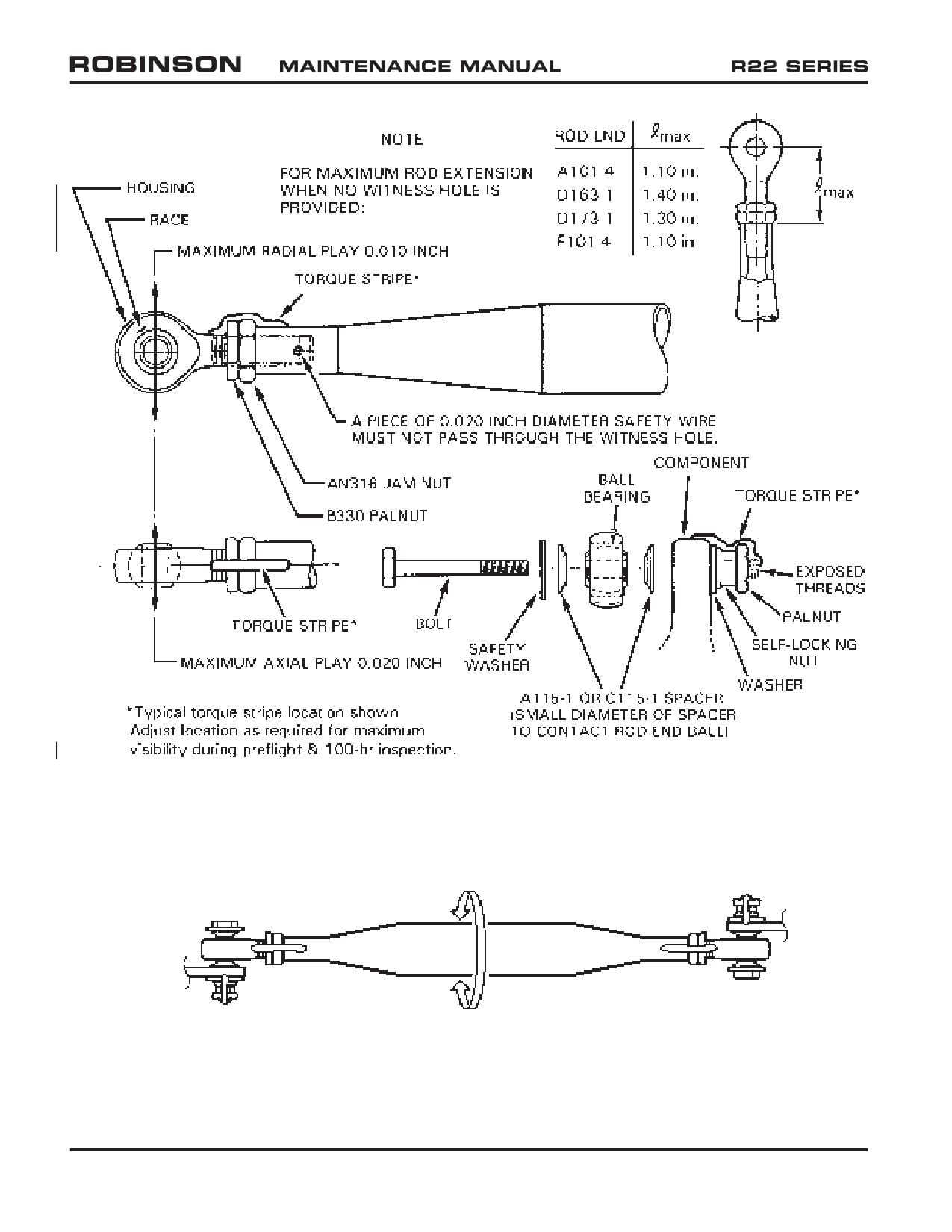
FIGURE 2-1 ROD END AND SPHERICAL BEARING PLAY LIMITS AND TORQUE STRIPE APPLICATION
FIGURE 2-1A ROD END CENTERING
(Position rod ends for maximum rotation)
Page 2.2
Chapter 2 Inspection
OCT 2018
2.120 Push-Pull Tubes, Rod Ends, and Spherical Bearings
2.121 Push-Pull Tubes
Nicks, cuts, or scratches in tube not more than 0.010 inch deep and not more than 1/4
of tube circumference may be polished out in lengthwise direction using 320-grit or finer
wet-or-dry abrasive paper and 1-inch minimum blend radius. If depth exceeds these
limits, tube must be replaced.
If tube is dented or flattened more than 5 percent of its diameter, it must be replaced.
2.122 Rod Ends and Spherical Bearings
Refer to Figure 2-1.
1. Maximum axial play: 0.020 inch
Maximum radial play: 0.010 inch
2. Looseness between bearing outer race and rod end housing is not permitted.
3. Rod ends not riveted in place must block passage of 0.020 inch diameter wire
through witness hole, if provided.
4. Rod end jam nuts and palnuts must be torqued per § 23-32 and torque striped, per
Figure 2-1, at the most visible position for pre-flight inspection. Torque stripe must
extend across nuts to both rod end shank and push-pull tube (or pitch link barrel,
yoke, support, strut, etc.). Torque stripes are subject to deterioration and must be
periodically renewed.
5. Rod ends must be centered, i.e., rod ends should be positioned to allow as much
movement as possible without binding.
WARNING
Assembly of flight controls is critical and requires inspection
by a qualified person. If a second person is not available, the
installer must take a 5-minute break prior to inspecting flight
control connections he has assembled.
CAUTION
Teflon-lined bearings must not be lubricated or solvent cleaned.
OCT 2018
Chapter 2 Inspection
Page 2.3
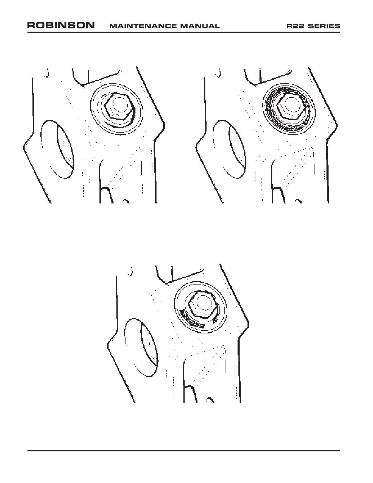
FIGURE 2-2A
FIGURE 2-2B
ELASTOMER FATIGUE
ELASTOMER OIL CONTAMINATION
FIGURE 2-2C
ELASTOMER OVERLOAD
Page 2.4
Chapter 2 Inspection
OCT 2018
2.125 Elastomeric Bearings
Elastomeric bearings are used in the A062-1 tail rotor hub. Fatigue, oil contamination, or
overload can degrade the elastomer.
Small surface cracks (fatigue cracks) and elastomer dust or “eraser crumbs” (see Figure
2-2A) are normal and are not causes for replacement. As cracks grow, enough elastomer
will be lost to cause reduced stiffness and increased vibration. If deep (greater than 0.10
inch) cracks are present over more than 25% of elastomer face, replace bearing.
Avoid exposure to oil, grease, hydraulic fluid, cleaning solvent, and rust-preventative fluids.
Immediately wash off any such contaminants with detergent and water. Contaminated
bearings exhibit swelling, wavy edges, or debonding (see Figure 2-2B) and must be
replaced.
Overload occurs when elastomer’s tensile strength or rubber-to-metal bond strength is
exceeded. This can occur when normal loads are applied to a bearing weakened by
fatigue or oil contamination. Overload is indicated by large extrusions from and large
clean cracks in elastomer as shown in Figure 2-2C.
Elastomer may also separate (debond) from metal bushings. If separation occurs over
more than 25% of bonded area, replace bearing.
OCT 2018
Chapter 2 Inspection
Page 2.5
2.130 Telatemp Indicators
Self-adhesive Telatemp indicators record changes in operating temperatures of bearings
and gearboxes. To use a Telatemp, draw a reference line between the highest temperature
square which has darkened during normal operation and the next undarkened square.
During every check thereafter, determine if an additional square has blackened. If
an indicated temperature increase cannot be accounted for by a change in operating
conditions, carefully examine the component before further flight.
NOTE
Telatemps can indicate erroneously if contaminated by a
petroleum product, typically appearing as white, unactivated
square(s) between darkened squares at each end; replace any
Telatemp indicating as such and clean area with acetone prior
to installing.
Part Number
Temperature Range
F110-2
60°C / 140°F
- 88°C / 190°F
F110-4
104°C / 220°F
- 132°C / 270°F
Usage
F110-4 on A006-1 Main Rotor Gearbox
F110-2 on A184-3 Upper Actuator Bearing (just aft of upper sheave)
F110-2 on A181-4 Lower Actuator Bearing (just aft of lower sheave)
F110-2 on A021-1 or B021-1 Tail Rotor Gearbox
2.140 Torque Stripes
If, during inspection, the remaining torque stripe on a fastener is insufficient to determine
joint integrity, then remove accompanying palnut as required and apply specified torqe
to fastener. If fastener moves, disassemble joint and inspect parts for damage such as
fretting, thread deformation, hole elongation, etc.; replace damaged parts. If fastener
does not move, install new palnut as required & standard torque per § 23-32. Torque
stripe fastener per Figure 2-1.
Page 2.6
Chapter 2 Inspection
OCT 2018
2.200 Ground and Flight Check for 100-Hour/Annual Inspection
Complete the following checklists in conjunction with a 100-hour or annual inspection.
Note and correct any discrepancies.
2.205 Ground Check
1. Throttle Control: Check for freedom of rotation with collective full down
and full up.
2. Throttle Overtravel Spring: Check by twisting throttle past idle position
to override stop. Release throttle and ensure it returns immediately to
normal idle position.
3. Mixture Control: Check for smoothness of operation with no binding.
Check press-to-unlock button for proper function. Verify 0.03 to 0.10
inch spring-back at full rich position.
4. Carburetor Heat Control: Check for smoothness of operation with no
binding. Verify 0.03 to 0.10 inch spring-back at full off position.
5. Cyclic Control: Check freedom through full travel with friction and
right trim off. Verify friction knob rotates 1/8 to 1 turn clockwise
before adding friction. Check full travel with friction and right trim
on. Verify 10 pounds maximum friction measured laterally at grip
with right trim off, friction on, and MR blade pitch links fore and aft.
6. Collective Control: Check freedom through full travel with friction off.
Check freedom through full travel with friction on; friction should be 12
to 20 pounds measured at grip.
7. Carb Heat Assist (if installed): With collective down and full carb heat,
raise collective full up and verify carb heat off. Lower collective full
down and verify carb heat full on. With collective friction off, push carb
heat off and verify collective stays down.
8. Tail Rotor Pedals: Check for smooth operation with no binding.
9. Removable Controls: Verify security of attached fasteners.
10. Lighting and Instruments: Turn MASTER switch on and verify -
a. Carbon Monoxide caution light blinks twice
b. Carb Air Temp approximately same as Outside Air Temp
c. ALT caution light on
d. OIL pressure warning light on
e. Fuel quantity gages - indication of fuel level
f. Navigation and panel lights - check function
g. Strobe light - check function
OCT 2018
Chapter 2 Inspection
Page 2.7
2.205 Ground Check (continued)
10. Lighting and Instruments: Turn MASTER switch on and verify - (continued)
h. Landing lights - check function
(clutch switch must be Engaged to check landing lights)
i. Map light - check function
j. Ammeter - shows discharge
k. Oil temperature gage - slight needle deflection with engine cold
l. Cylinder head temp gage - slight needle deflection with engine cold
m. MR CHIP light - on when sender shorted or test switch depressed
n. MR TEMP light - on when sender shorted or test switch depressed
o. TR CHIP light - on when sender shorted or test switch depressed
p. LOW FUEL light - on after approximately 1 second delay when low
fuel sender in tank is depressed or when test switch depressed
Page 2.8
Chapter 2 Inspection
OCT 2018
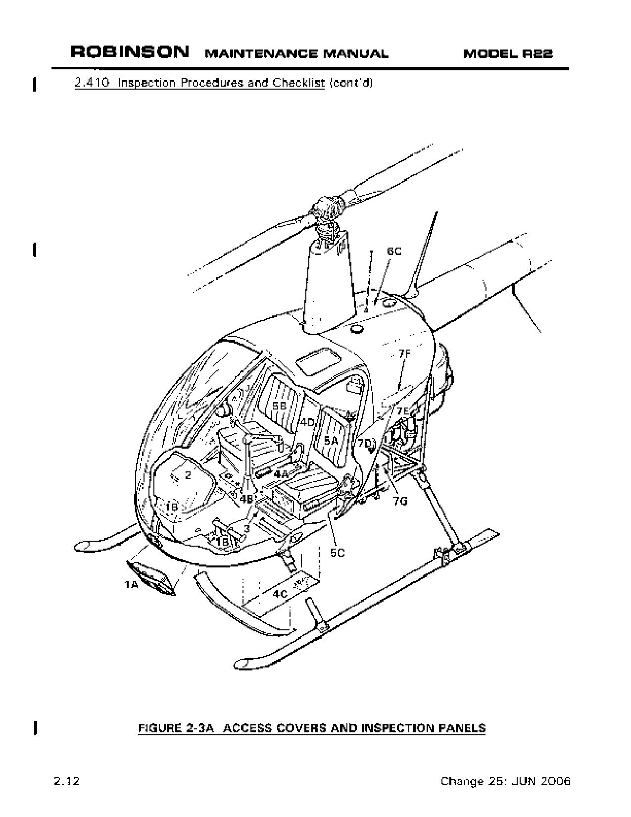
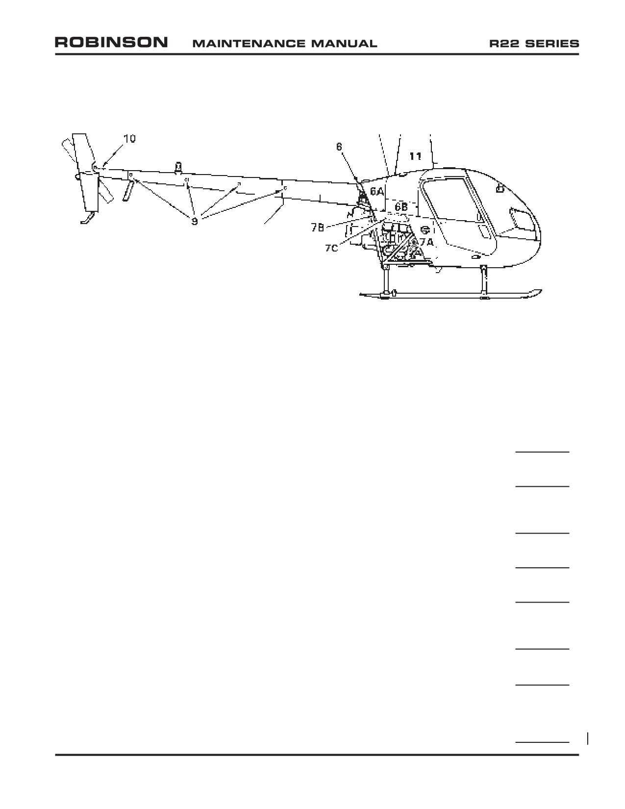
2.410 Inspection Procedures and Checklist (continued)
FIGURE 2-3B ACCESS COVERS AND INSPECTION PANELS
2. Open Upper Console Assembly (2) or Lower Faceplate per Section 14.1020
(10-hole instrument console only)
Upper Console Assembly: Inspect condition. Verify hinge security.
Instruments and Instrument connections: Inspect condition. Verify
security.
Strobe Power Supply and Wiring (alternate locations - atop horizontal
firewall or behind right seat back): Inspect condition. Verify no cracks in
mounting area. Verify security.
B255-1 Bracket (10-hole instrument console only): Inspect condition of
grommet and bracket contacting brace assembly between windshields.
Tail Rotor Push-Pull Tubes: Inspect condition of visible portions. Verify
operating clearance.
Battery and Box (if installed in nose): Inspect condition. Check battery
cell fluid level and specific gravity (non-sealed battery only). Verify
security of connections. Verify no corrosion in surrounding structure.
Radio Tray(s): Inspect condition. Verify security. Verify no loose or poor
wire connections.
Fasteners & Torque Stripes: Inspect condition and verify security of all
fasteners. Renew deteriorated torque stripes per Figure 2-1.
Wiring: Inspect condition. Verify neatness, security, and no chafing.
OCT 2018
Chapter 2 Inspection
Page 2.13
2.410 Inspection Procedures and Checklist (continued)
5. Remove Seat Backs (5A & 5B) & Collective Spring Guard (5C under left seat)
Seat Backs and Collective Spring Guard: Inspect condition. Verify
upholstery security.
Upper Frame Assembly: Inspect condition of visible portions. Verify
security.
Electrical and Antenna Wiring: Inspect condition. Verify security. Verify
no chafing. Check grommets for proper installation.
Pitot and Static Lines: Inspect condition. Verify no chafing or kinks.
Collective Stick Assembly: Inspect condition. Inspect bearings per
§ 2.120. Verify security and operating clearance. Verify no cracks in
welds. Verify security of removable stick (if installed). If applicable, verify
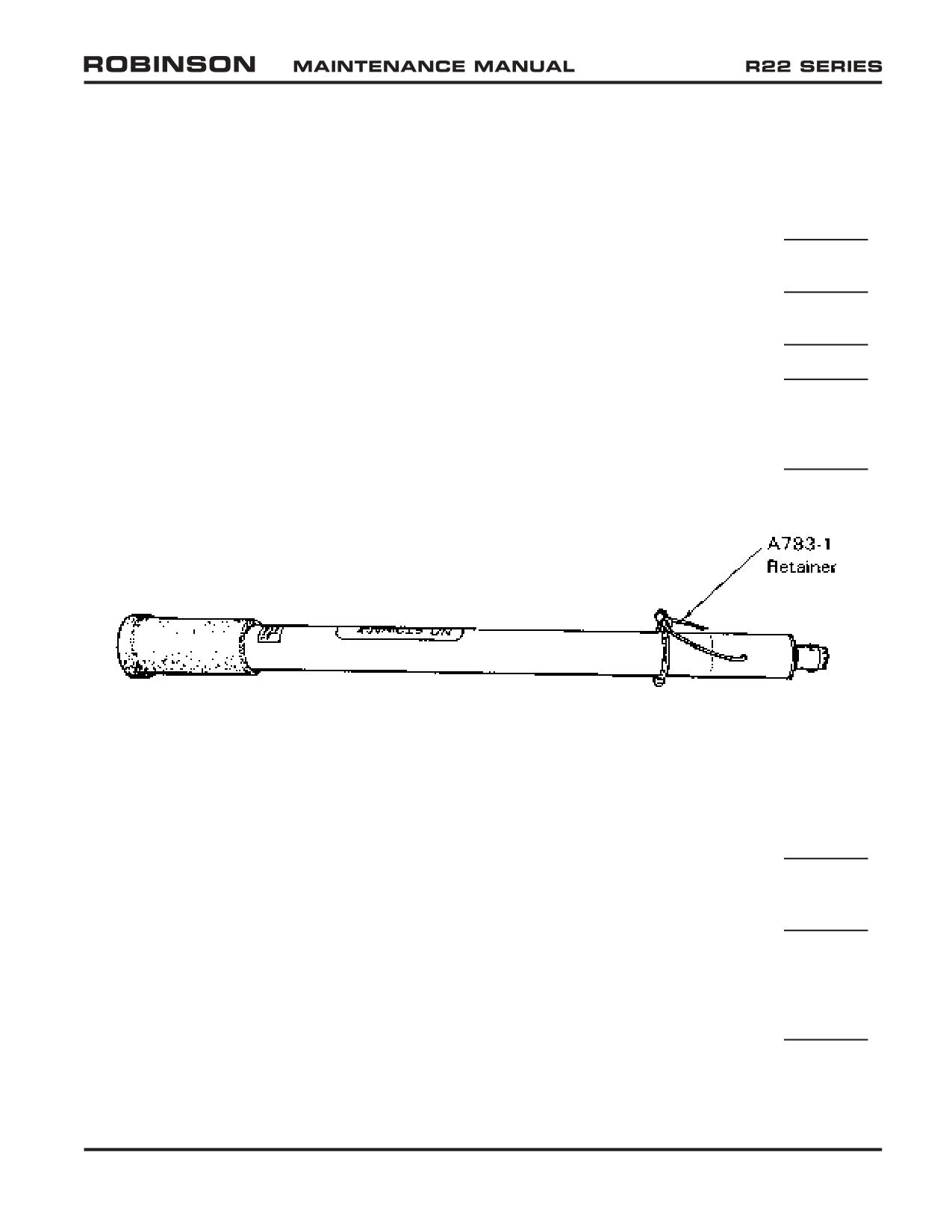
A783-1 retainer is secured to collective stick with ty-raps per Figure 2-4.
FIGURE 2-4 A783-1 RETAINER SECURITY
Throttle Connecting Rod: Inspect condition. Verify no cracks. Verify
security and operating clearance.
Governor: Inspect condition. Inspect rod ends per § 2.120. Verify
security and operating clearance. Verify sufficient wiring slack with full
up collective.
Collective Spring: Inspect condition. Inspect rod ends per § 2.120. Verify
no binding or roughness during operation. Verify lubrication of guide rods.
Verify spring coils do not touch each other when collective is full down.
Verify no elongation of lower cap guide rod holes. Verify security and
operating clearance.
OCT 2018
Chapter 2 Inspection
Page 2.17
2.410 Inspection Procedures and Checklist (continued)
5.
Remove Seat Backs (5A & 5B) & Collective Spring Guard (5C under left seat) (continued)
Firewall Drains: Inspect condition. Verify drains are unobstructed. Verify
tubing clamps are not cutting tubing. Verify security.
Governor Controller and Wiring: Inspect condition. Verify security.
Main Fuel Tank Outlet & Fuel Line: Inspect condition. Verify no leakage.
Verify security. Verify smooth operation of fuel valve.
Fuel Shut-Off Valve: Inspect condition. Verify no leakage. Verify security.
Verify smooth operation of fuel valve.
Aux Fuel Tank Fuel Line: Inspect condition. Verify clearance to structure.
Verify no leakage. Verify security.
Fasteners & Torque Stripes: Inspect condition and verify security of all
fasteners. Renew deteriorated torque stripes per Figure 2-1.
6.
Open Cowling Door(s) (6A & 6B) & Remove aft Cowling (6C)
Cowling Doors: Inspect condition. Verify proper operation of fasteners.
Electrical Wiring: Inspect condition. Verify no loose, broken, or chafed
wires. Verify neatness and security.
Actuator Fuse(s) and Holder(s): Inspect condition. Verify no corrosion.
Verify correct AGC-1½ fuse(s), twist-to-lock function, and security.
Antennas and Connections: Inspect condition. Verify security of antenna(s)
and antenna connection(s).
Emergency Locator Transmitter (if installed): Inspect condition. Verify
security. If applicable, comply with U.S. 14 CFR 91.207 (d).
Pitot Line and Static Vent: Inspect condition. Verify no chafing, kinks, or
tight bends. Verify static vent is clean and unobstructed.
Fuel Tanks: Inspect condition of visible portion. Verify no leaks. Verify
security. Check interior for foreign objects and cracks in baffle.
Aux Fuel Tank Fuel Line: Inspect condition. Verify clearance to structure.
Verify no leakage. Verify security.
Fuel Gage Sender(s) and Wiring: Inspect condition. Verify no fuel leaks.
Page 2.18
Chapter 2 Inspection
OCT 2018
2.410 Inspection Procedures and Checklist (continued)
6. Open Cowling Door(s) (6A & 6B) & Remove Aft Cowling (6C) (continued)
Fuel Tank Sump Drain(s): Inspect condition. Verify drain valve(s) open
easily, drain fuel freely, spring closed, and seal completely.
Low Fuel Warning: Turn battery on. With a clean wooden dowel, gently
depress low fuel sender float in main fuel tank and verify LOW FUEL warning
light illuminates after approximately 1 second delay. Turn battery off.
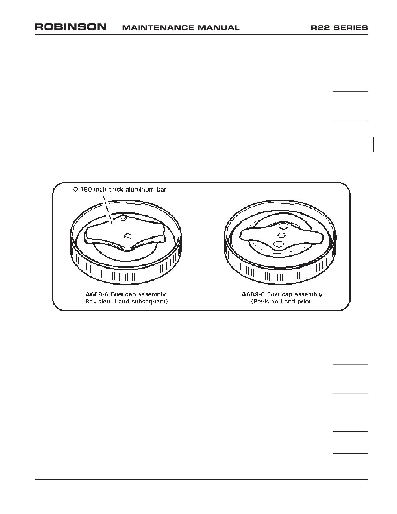
Fuel Cap(s): Refer to Figure 2-4A. Verify A689-6 fuel cap is revision J
or subsequent if bladder tanks are installed (revision J or subsequent caps
may also be used on all-aluminum tanks). Inspect condition. Verify no
deterioration of gasket(s). Verify security when closed. Refer to R22
SB-107; verify cap decal is legible and properly installed, and alignment
marks on cap and tank align when cap is fully closed.
FIGURE 2-4A A689-6 FUEL CAPS
Collective Jackshaft Supports: Inspect condition. Inspect rod ends per §
2.120. Verify no cracks or corrosion. Verify strut ends are sealed. Verify
security.
Collective Jackshaft: Inspect condition. Verify no cracks or corrosion. If
open type, verify no internal corrosion. Verify security. Verify operating
clearance.
Swashplate Push-Pull Tubes: Inspect condition of visible portions. Verify
no cracks at ends. Inspect rod ends per § 2.120. Verify no tears in,
or wear through, heat-shrink sleeves on forward push-pull tubes. Verify
security and operating clearance.
Push-Pull Tube Guides or Rollers: Inspect condition. Verify cleanliness, no
wear into metal, and free movement of rollers. Verify security.
OCT 2018
Chapter 2 Inspection
Page 2.19
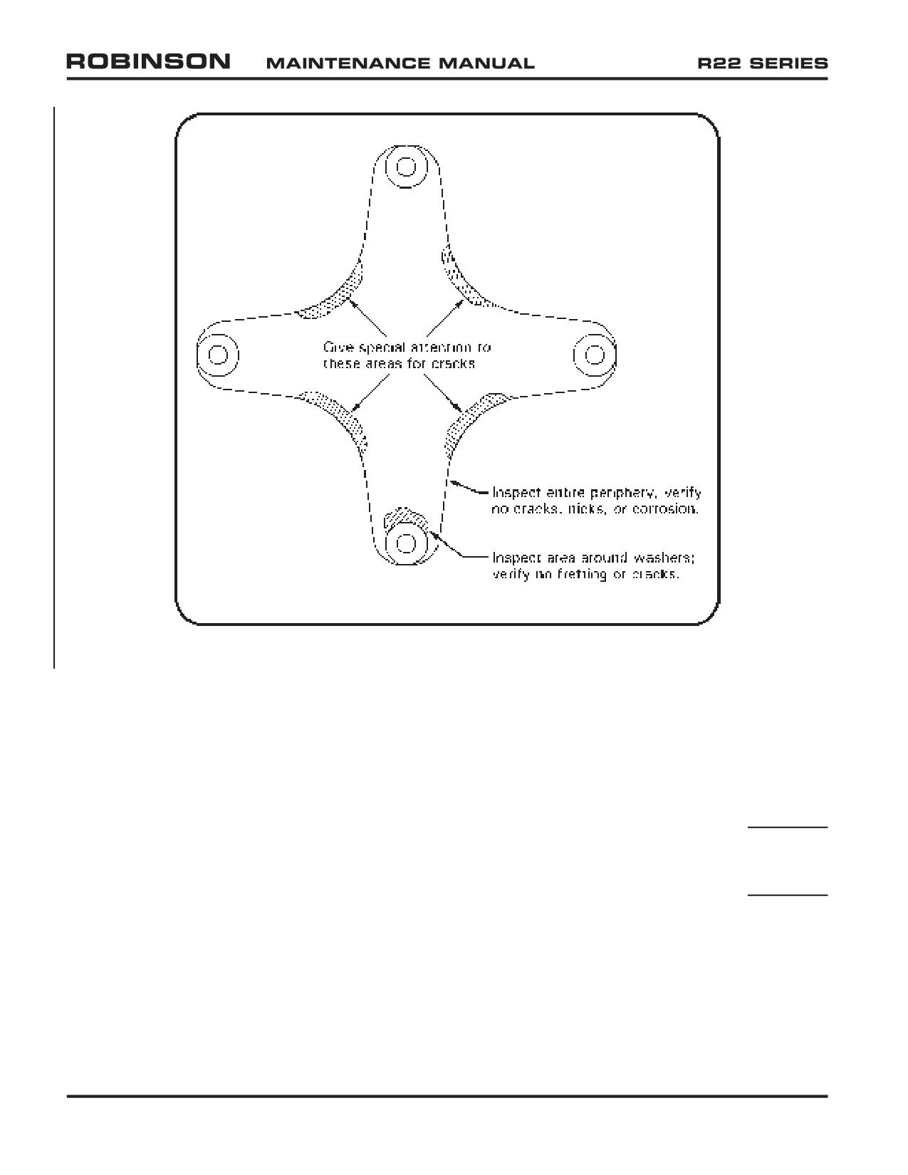
FIGURE 2-4B A947-1 FLEX PLATE INSPECTION
2.410 Inspection Procedures and Checklist (continued)
6. Open Cowling Door(s) (6A & 6B) & Remove Aft Cowling (6C) (continued)
Tail Rotor Push-Pull Tube and Bellcrank (at forward end of A121-15 push-
pull tube): Inspect condition. Inspect rod ends per § 2.120. Verify no
cracks in tube ends. Verify no cracks at bellcrank sheet metal mounting.
Verify security and operating clearance.
Main Rotor Gearbox Cooling Air Duct and Nozzle: Inspect condition. Verify
security. Verify no rips, holes, chafing, or obstructions. Inspect condition
and verify security of horizontal firewall grommet around duct.
Page 2.20
Chapter 2 Inspection
OCT 2018
2.410 Inspection Procedures and Checklist (continued)
6. Open Cowling Door(s) (6A & 6B) & Remove Aft Cowling (6C) (continued)
Main Rotor Gearbox: Inspect condition, especially gearbox mounts,
static mast tube-to-gearbox attachment, and mast tube lower casting (if
applicable). Inspect Telatemp per § 2.130. Verify proper oil level with no
leakage. Verify security. Verify security of Hall Effect senders.
NOTE
At 500 hours time in service or annually, whichever occurs
first, remove chip detector and clean any varnish accumulation
from detector’s magnetic probe and adjacent metal body using
a toothbrush and approved solvent per § 22-11. Drain and flush
gearbox at intervals not to exceed 500 hours time in service
(refer to § 22-13).
Rotor Brake: Inspect condition, including activating cable & pulley and
microswitch. Verify integrity of brake pads and 0.030 inch minimum pad
thickness. Verify brake pad clearance to input yoke when brake is off.
Verify security and operating clearance.
MRGB Input Yoke: Inspect condition. Verify security and operating
clearance. Verify security of magnets.
Forward Flex Plate: Refer to Figure 2-4B. Inspect condition. Verify no
distortion, nicks, scratches, cracks, corrosion, or fretting. If fretting is
detected, contact RHC Technical Support. Verify bonded washers are
installed on both sides of each flex plate ear. Verify proper installation,
security, and operating clearance.
WARNING
A193 flex plates, which do not have bonded washers, are
obsolete and must be replaced with A947 flex plates having
bonded washers. If a bonded washer separates from an A947
flex plate, flex plate is unairworthy and cannot be repaired.
Ensure A947-1 forward flex plate is Rev E or subsequent
(identified by letter, “E” or subsequent letter, on two adjacent
arms of flex plate).
Clutch Shaft Forward Yoke: Inspect condition. Verify no cracks, corrosion,
or fretting. Verify security and operating clearance.
Clutch Assembly: Inspect condition. Verify no oil leakage. Verify no clutch
shaft corrosion, especially at shaft-to A966-1 seal junctures. Remove any
light surface corrosion at shaft-to-seal junctures and apply wax or suitable
corrosion preventative compound. Verify no cracks in seal retainer plates.
NOTE
Clutch assembly lubricant inspection and servicing (§ 7.214) is
recommended every 500 hours time in service.
OCT 2018
Chapter 2 Inspection
Page 2.21
2.410 Inspection Procedures and Checklist (continued)
6.
Open Cowling Door(s) (6A & 6B) & Remove Aft Cowling (6C) (continued)
Upper Sheave: Inspect condition. Verify smoothness of drive belt contact
surfaces. Replace any sheave having corrosion, pitting, flaking, roughness,
sharp ridges, wear through anodized coating, or blistering of optional
metalized coating.
Upper Steel Tube Frame: Inspect condition. Verify no cracks or corrosion.
If corrosion is found, inspect and repair per § 2.560. Use an inspection
light and mirror to inspect all parts of each weld.
CAUTION
Upper steel tube frame is fatigue loaded and therefore susceptible
to fatigue cracks. Inspect all joints very thoroughly.
Horizontal Firewall: Inspect condition, especially where bolted to steel
structure. Verify no cracks, buckling, or wrinkles.
Cabin Aft Bulkhead: Inspect condition. Verify no corrosion, loose rivets,
deformation, or cracks.
Fasteners & Torque Stripes: Inspect condition and verify security of all
fasteners. Renew deteriorated torque stripes per Figure 2-1.
7.
Remove Side Skirts (7A, 7B, 7D, & 7E), Spark Plug Access Covers (7C & 7F), and
Battery Box Cover (7G, alternate location under upper console or left seat)
Engine: Refer to Lycoming Operator's Manual (Lycoming P/N 60297-12 or
60297-16, as applicable) Sections 4 and 5 and Lycoming Sl 1080 (current
revision) for 100-hour or annual inspection and service procedure.
Muffler: Open heater shroud (if installed). Inspect muffler condition.
Verify no cracks or ruptures. Pay particular attention to tail pipe and riser
attachment areas, welds, clamps, riser flanges and gaskets. Verify no
internal obstructions.
Muffler Leak Check: Pressurize muffler with low pressure air and inspect
for leakage by applying soapy water to exterior and looking for air bubbles.
Verify security.
WARNING
Exhaust system failure can result in carbon monoxide poisoning,
partial loss of power, or fire.
Heater Shroud (if installed): Inspect condition. Close and secure shroud
and connect hoses.
Engine Cooling Panels: Inspect condition. Pay particular attention to panel
attached to oil cooler and panel attached to alternator cooling hose. Verify
no cracks or missing or loose fasteners. Verify security.
Page 2.22
Chapter 2 Inspection
OCT 2018
2.410 Inspection Procedures and Checklist (continued)
7. Remove Side Skirts (7A, 7B, 7D, & 7E), Spark Plug Access Covers (7C & 7F), and
Battery Box Cover (7G, alternate location under upper console or left seat) (continued)
Alternator & Pulley: Inspect condition. Verify steel pulley (use magnet);
aluminum pulley is not approved. Verify security.
Alternator Wiring: Inspect condition. Verify no evidence of arcing. Verify
security of output, aux, and field terminal studs. Verify no damage to
insulating spacer at output stud. Verify wiring security.
Alternator Belt: Inspect condition. Replace belt if there are any cracks,
missing teeth or delamination. Check tension per Lycoming Service
Instruction 1129 (current revision). Verify proper belt alignment.
Emergency Spare Alternator Belt: Remove if installed.
Alternator Cooling Hose: Inspect condition. Verify no obstructions or
holes. Verify security.
Vertical Firewall: Inspect condition. Verify no cracks, buckling, or wrinkles,
especially around structural attachment points.
Lower Steel Tube Frames: Inspect condition. Verify no corrosion or cracks,
especially at welds. If corrosion is found, inspect and repair per § 2.560.
Verify proper torque (see § 23-32) and safety wiring of drilled-head bolt at
lower left frame-to-cabin-belly attachment.
Engine Mounts: Inspect condition. Verify security. Replace rubber mounts
exhibiting significant deflection or other than superficial cracks.
Throttle Control: Verify carburetor butterfly bellcrank contacts idle rpm
adjustment screw with collective full down and throttle grip at idle position.
Verify bellcrank contacts full-open stop when throttle is opened with
collective half-up. Inspect rod end per § 2.120. Verify operating clearance,
especially at vertical firewall.
Throttle Correlation Rigging: Check per § 10.150 and adjust as required.
Full Throttle Switch Rigging: Check per § 33-60 and adjust as required.
Carburetor Mixture Control: Verify carburetor mixture control moves
carburetor mixture control arm stop to stop. Inspect condition and verify
security of mixture control cable clamp(s) on air box bracket; push and pull
cable housing to ensure it does not slip in clamp(s). Inspect condition and
verify security of mixture control cable inner wire attachment to carburetor
mixture control arm. Ensure freedom of rotation between mixture control
arm and inner wire retention fitting (bolt) when arm moves. Verify mixture
control safety spring is properly installed (so spring force moves mixture
control arm to full-rich position if inner wire breaks).
Engine Electrical Wiring, Alternator Control Unit: Inspect condition. Verify
no wire chafing. Inspect connections. Verify security and no corrosion.
OCT 2018
Chapter 2 Inspection
Page 2.23
2.410 Inspection Procedures and Checklist (continued)
7. Remove Side Skirts (7A, 7B, 7D, & 7E), Spark Plug Access Covers (7C & 7F), and
Battery Box Cover (7G, alternate location under upper console or left seat) (continued)
Oil Lines & Elbows: Inspect condition. Verify clearance and no cracks or
abrasions. Wires, ty-raps, and structure must not contact lines.
Oil Line Clamps: Inspect condition. Verify no broken clamps.
Oil Cooler: Inspect condition. Verify no cracks or leakage. Verify security.
Verify airflow path through cooling fins is unobstructed.
Gascolator: Inspect condition. With fuel valve in OFF position, remove and
clean gascolator bowl and filter screen. Reinstall bowl, turn fuel valve ON.
Safety wire retainer after ensuring no leakage. Verify drain valve opens
easily, drains fuel freely, springs closed, seals completely, and is torque-
striped per § 23-31.
Fuel Hose: Inspect condition, verify security, clearance, no cracks, abrasion
or leakage.
Carburetor Air Box: Open air box. Inspect condition. Verify free movement
of disk in drain valve (not applicable to Mariners). Verify security. If
installed, verify free movement and full closure of spring-loaded alternate
air door.
Carburetor Heat Valve: Verify carburetor heat control fully opens and
closes slider valve. Inspect condition and verify security of carburetor heat
cable clamp on air box. Inspect condition and verify security of carburetor
heat control cable inner wire attachment to slider valve.
Air Filter: Clean B771-1 air filter per § 6.435. Close and secure air box.
Carburetor Air Inlet Hose: Inspect condition. Verify no obstructions,
leakage, or chafing. Verify security.
Carburetor Heat Scoop and Hose: Inspect condition. Verify security.
Verify no obstructions, leakage, chafing, or scoop cracks.
Heater Hoses (if installed): Inspect condition. Verify security and no
obstructions, leakage, or chafing. Verify security.
Battery, Battery Cables, and Battery Box (alternate locations under upper
console or left seat): Inspect condition. Check each battery cell electrolyte
for quantity and specific gravity (non-sealed batteries only). As required,
perform capacity test or replace battery per manufacturer’s instructions.
Verify battery cable security and no cracked or corroded terminals. Verify
security of, and no obstructions in, battery box drain tube (if installed).
Fasteners & Torque Stripes: Inspect condition and verify security of all
fasteners. Renew deteriorated torque stripes per Figure 2-1.
Page 2.24
Chapter 2 Inspection
OCT 2018
2.410 Inspection Procedures and Checklist (continued)
8. Remove Tailcone Fairing (8)
Tailcone Fairing: Inspect condition.
Upper Steel Tube Frame: Inspect condition. Verify no cracks or corrosion.
If corrosion is found, inspect and repair per § 2.560. Use an inspection
light & mirror to inspect all parts of each weld.
CAUTION
Upper steel tube frame is fatigue loaded and therefore susceptible
to fatigue cracks. Inspect all joints thoroughly.
Tailcone-to-Upper Frame Attachment: Inspect condition. Verify security.
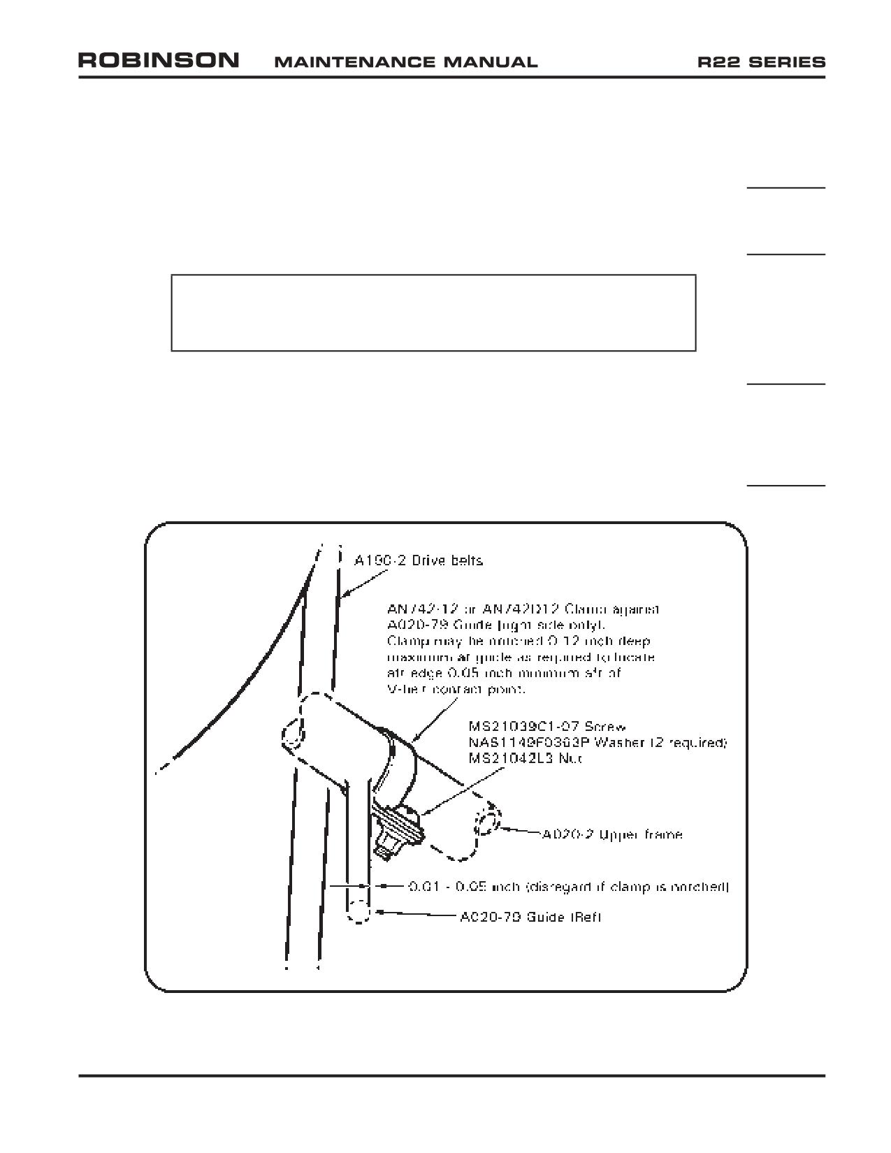
Upper Frame Protective Clamp: Inspect clamp protecting right side upper
frame tube from drive belt contact; replace if wear has penetrated clamp.
If clamp is not installed, verify no more than 0.0049 inch wear into frame
tube due to drive belt rubbing. Protective clamp may be installed per Figure
2-4C on any R22 if desired.
FIGURE 2-4C UPPER FRAME PROTECTIVE CLAMP INSTALLATION
(View looking forward)
OCT 2018
Chapter 2 Inspection
Page 2.25
2.410 Inspection Procedures and Checklist (continued)
8. Remove Tailcone Fairing (8) (continued)
Actuator Upper Bearing: Inspect condition. Verify no more than 0.060 inch
axial play. Verify no fretting between bearing inner race and clutch shaft.
Verify bearing inner race has not slipped relative to clutch shaft. Inspect
Telatemp per § 2.130. Perform § 22-41 bearing inspection if unexplainable
Telatemp increase has occurred.
CAUTION
A184 bearing requires periodic lubrication per § 1.101.
Actuator Upper Bearing Lubrication: Perform as required.
Clutch Lateral Centering Strut Assembly: Inspect condition. Inspect rod
ends per § 2.120. Verify security.
Intermediate Flex Plate and Yokes: Refer to Figure 2-4B. Inspect condition.
Verify no distortion, nicks, scratches, cracks, corrosion, or fretting. If
fretting is detected, contact RHC Technical Support. Verify bonded washers
are installed on both sides of each flex plate ear. Verify proper installation,
security, and operating clearance.
WARNING
A193 flex plates, which do not have bonded washers, are
obsolete and must be replaced with A947 flex plates having
bonded washers. If a bonded washer separates from an A947
flex plate, flex plate is unairworthy and cannot be repaired.
Tail Rotor Push-Pull Tubes and A331-1 Bellcrank: Inspect condition. Verify
no cracks at tube ends. Inspect rod ends per § 2.120. Verify security and
operating clearance.
Drive V-Belts: Inspect per § 2.507.
Fanshaft: Inspect condition. Perform 360° visual inspection of exposed
fanshaft for cracks. Verify security and safety wiring of attaching bolts.
Actuator Lower Bearing: Inspect condition, verify bearing inner race has
not slipped relative to fanshaft. Inspect Telatemps per § 2.130. Perform §
22-42 bearing inspection if unexplainable Telatemp increase has occurred.
CAUTION
A181-4 bearing requires periodic lubrication per § 1.101.
Actuator Lower Bearing Lubrication: Perform as required.
Lower Bearing Brackets: Verify no looseness or cracking in A185 brackets
which secure actuator lower bearing to scroll.
Fiberglass Scroll: Inspect condition. Verify no damage to vane assembly in
upper right scroll. Verify security. Verify drain hole is unobstructed.
Page 2.26
Chapter 2 Inspection
OCT 2018
2.410 Inspection Procedures and Checklist (continued)
8. Remove Tailcone Fairing (8) (continued)
Scroll Metal Inlet Lips & Gap (if installed): Inspect condition. Verify 0.020
to 0.100 inch gap between lips and fanwheel inlet. (Attach holes in lips
may be elongated to facilitate gap adjustment.)
Fanwheel Assembly: Inspect condition. Verify no cracks or corrosion.
Check leading edge of vanes for damage. Verify alignment of roll pin and
slippage marks on fanwheel. If marks and roll pin do not align, remove
fanwheel and inspect hub and shaft for damage. Verify security.
Actuator (A051-1): Turn master switch on and engage clutch switch. While
actuator is engaging, depress extension limit switch lever and verify gear
motor stops; release lever and verify gear motor resumes running. Use
an inspection mirror to observe column springs at end of belt-tensioning
cycle; springs should snap outward simultaneously. Verify maximum
engaged extension limit per Figure 7-15 is not exceeded. Verify security of
attachment to A181 and A184 bearings. Verify gear motor security and
minimum 0.030 inch clearance to upper frame.
Actuator Spring Switches: Check using either of following two methods,
as appropriate:
Method 1 - (actuator electrical harness must be equipped with “Test” plug)
CAUTION
When using MT558-1 plug assembly (see Figure 2-5), if gear
motor does not shut off when column springs snap outward
then spring switch has failed in closed position; immediately
remove MT558-1 to prevent actuator damage.
a. Disengage actuator. Connect one end of MT558-1 to actuator test
plug. Engage actuator and verify gear motor shuts off when column
springs snap outward.
b. Disengage actuator. Connect opposite end of MT558-1 to actuator
test plug. Engage actuator and verify gear motor shuts off when
column springs snap outward.
c. MT558-1 pins 1-2 jumper tests the wire 98 spring switch; the pins
2-3 jumper tests the wire 91 spring switch (see Figure 14-4A). If
either switch does not function properly, replace switch section per
§ 7.551 before further flight.
FIGURE 2-5
OCT 2018
Chapter 2 Inspection
Page 2.27
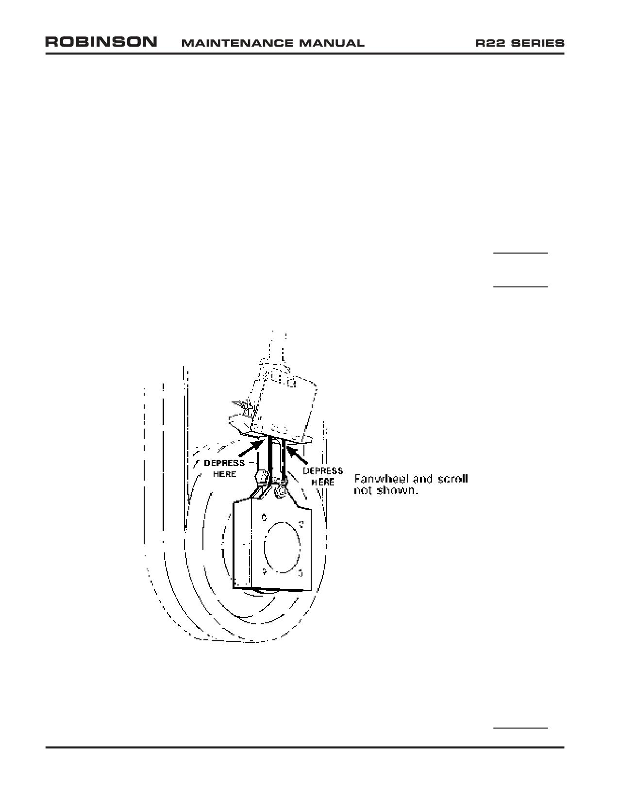
2.410 Inspection Procedures and Checklist (continued)
8. Remove Tailcone Fairing (8) (continued)
Actuator Spring Switches (continued):
Method 2 - (use if actuator electrical harness is not equipped with “Test”
plug)
a. Refer to Figure 2-5A. Depress column springs on one side of actuator
until springs snap inward (use large screwdriver or similar tool with
several layers to tape over end to protect actuator). Hold springs
inward for at least one second. Actuator motor should not run. If
motor starts, allow motor to run approximately two seconds, then
release pressure on column springs. Depress column springs again. If
motor starts again, opposite spring switch does not function properly.
b. Disengage and re-engage actuator. Repeat step a. on opposite-side
column springs.
c. If either switch does not function properly, replace switch per §
7.551 before further flight.
FIGURE 2-5A ACTUATOR FUNCTION TEST
Lower Sheave: Inspect condition. Verify smoothness of drive belt contact
surfaces. Remove any surface corrosion and refinish with approved
primer. Replace any sheave showing corrosion-pitting or flaking of
metalized coating, roughness, or sharp ridges.
Page 2.28
Chapter 2 Inspection
OCT 2018
2.410 Inspection Procedures and Checklist (continued)
8.
Remove Tailcone Fairing (8) (continued)
Engine Height: Check per § 6.130 and adjust as required.
Clutch Shaft Angle: Check per § 7.240. Replace drive belts as required.
Sheave Alignment: Check per § 7.230 and adjust as required.
Throttle Correlation Rigging: Check per § 10.150 and adjust as required.
Fasteners & Torque Stripes: Inspect condition and verify security of all
fasteners. Renew deteriorated torque stripes per Figure 2-1.
9.
Remove 4 Tailcone Inspection Covers (9) : Verify nutplate self-locking
feature when removing.
Inspection Covers: Inspect condition.
Tail Rotor Drive Shaft: Inspect condition. Verify no cracks, bends, or
contact with inside of tailcone. Refer to Figure 7-12C for corrosion
limitations. Check runout per § 7.340.
Tail Rotor Push-Pull Tube: Inspect condition. Inspect rod ends per §
2.120. Verify wear does not exceed § 2.120 limits. Verify no cracks in
ends. Verify operating clearance. Verify tail rotor guard mounting screw
shanks clear push-pull tube.
Damper: Inspect condition. Verify security. Verify bearing housing wear
is within Figure 2-6 limits.
Tailcone Interior: Inspect condition. Verify no loose rivets or corrosion.
Verify no excessive wear in tail rotor push-pull tube bushings. Verify no
cracks, especially at damper-to-tailcone attachment.
Lower, Whip Antenna (if installed): Remove four screws securing antenna
mounting plate to tailcone. Verify no cracks or corrosion on mounting
plate or tailcone mount. Inspect antenna and wiring condition. Install
antenna. Verify security.
Upper Antenna(s) (if installed): Inspect antenna and wiring condition.
Verify security and no cracks at attachment to tailcone.
Tailcone Exterior: Inspect condition. Refer to Figures 2-7A and 2-7B for
dent and scratch limits. Verify no cracks, corrosion, fretting between
skin joints, or loose rivets. Verify drain hole at forward edge of each bay
(except forward) is unobstructed.
Tail Rotor Visual Warning Guard: Inspect condition. Verify no cracks or
corrosion, especially at tailcone attachment. Verify security.
Strobe Light: Inspect condition. Verify cleanliness and security.
Fasteners & Torque Stripes: Inspect condition and verify security of all
fasteners. Renew deteriorated torque stripes per Figure 2-1.
OCT 2018
Chapter 2 Inspection
Page 2.29
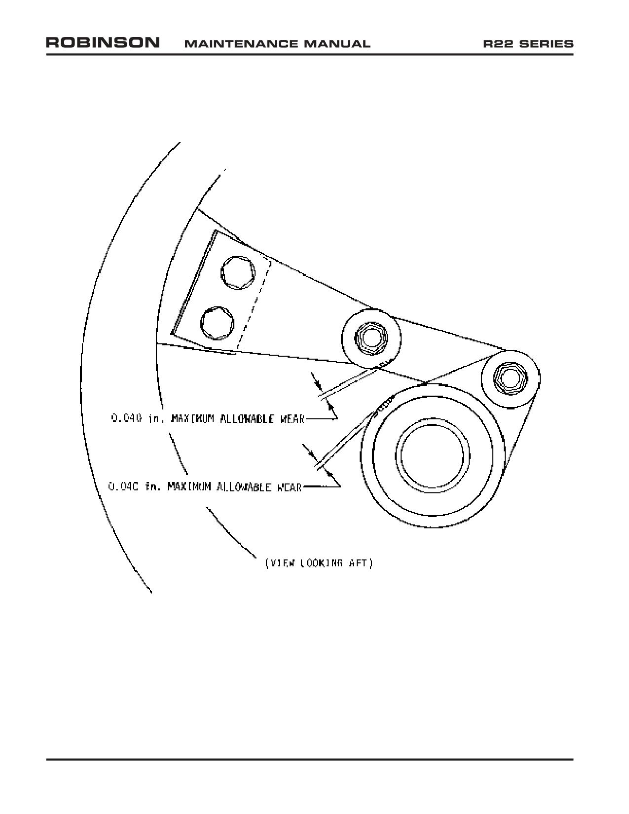
FIGURE 2-6 DAMPER BEARING HOUSING WEAR LIMITS
Page 2.30
Chapter 2 Inspection
OCT 2018
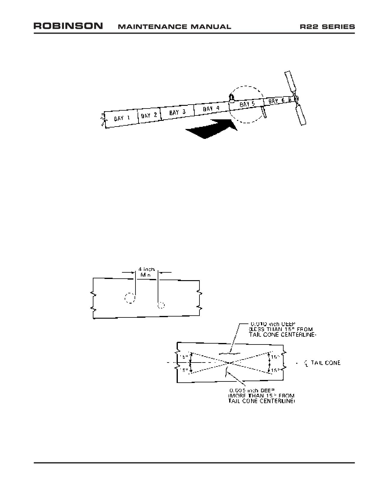
2.410 Inspection Procedures and Checklist (continued)
9. Remove 4 Tailcone Inspection Covers (9) (continued)
FIGURE 2-7A TAILCONE DENT LIMITS
BAY 5:
0.00 to 0.10 inch deep - No repair required provided 4 inches minimum between
dented stations.
0.10 to 0.25 inch deep - Repair per § 4.314.
Greater than 0.25 inch deep - Replace bay (requires return to RHC).
ANY OTHER BAY:
Dents with 0.030 inch maximum depth, 1.25 inch maximum diameter, and 0.125 inch
minimum bottom radius are acceptable if there is no more than one dent per station
with 4 inches minimum between dented stations. Otherwise, replace tailcone or
return to RHC for repair.
FIGURE 2-7B TAILCONE SCRATCH LIMITS
Allowable scratch depth varies with scratch angle to tailcone centerline as shown.
For scratches within these limits, polish out scratches using 320-grit or finer abrasive
paper and minimum 0.10 inch blend radius. Polish parallel to tailcone long axis. If
scratches exceed limits, replace tailcone or return to RHC for repair.
OCT 2018
Chapter 2 Inspection
Page 2.31
2.410 Inspection Procedures and Checklist (continued)
10. Remove Plastic Cover (10)
Plastic Cover: Remove and clean. Inspect condition. Replace as required
and install. Verify nutplate self-locking feature when installing.
Empennage: Inspect condition. Verify security. Verify no cracks or
loose fasteners. Verify lower vertical stabilizer and tail skid drain holes
are unobstructed. Refer to special inspection section for tail skid strike
inspection criteria.
Aft Navigation Light: Inspect condition. Verify cleanliness, clear lens,
and security.
Aft Flex Plate: Refer to Figure 2-4B. Inspect condition. Verify no
distortion, nicks, scratches, cracks, corrosion, or fretting. If fretting is
detected, contact RHC Technical Support. Verify bonded washers are
installed on both sides of each flex plate ear. Verify proper installation,
security, and operating clearance.
WARNING
A193 flex plates, which do not have bonded washers, are
obsolete and must be replaced with A947 flex plates having
bonded washers. If a bonded washer separates from a A947
flex plate, flex plate is unairworthy and cannot be repaired.
Tail Rotor Gearbox: Inspect condition, including seals. Verify proper
oil level and no leakage. Verify security and safety wire integrity. Verify
output shaft cleanliness.
NOTE
At 500 hours time in service or annually, whichever occurs
first, remove chip detector and clean any varnish accumulation
from detector’s magnetic probe and adjacent metal body using
a toothbrush and approved solvent per § 22-21. Drain and flush
gearbox at intervals not to exceed 500 hours time in service
(refer to § 22-23).
Page 2.32
Chapter 2 Inspection
OCT 2018
2.410 Inspection Procedures and Checklist (continued)
10. Remove Plastic Cover (10) (continued)
Tail Rotor Pitch Control Assembly and Aft Bellcrank: Inspect condition.
Inspect spherical bearing in underside of pitch control per § 2.120; it
is permissible to have a single radial crack in this spherical bearing ball.
Verify no excessive looseness on output shaft (0.25 inch maximum
rotational play measured at pitch link attaching bolt head). Verify
operating clearance and assembly slides freely on output shaft. Verify
no leakage at bearing seals. Verify security.
WARNING
A031-1 Rev. J or prior pitch control assemblies require repetitive
inspection per R22 Service Bulletin SB-90A every 300 hours or
annually, whichever occurs first.
Pitch Links: Inspect condition. Inspect rod ends and spherical bearings
per § 2.120. If pitch links are one-piece type, remove and reinstall with
outboard end inboard and inboard end outboard as required to obtain
maximum service life. Verify security and operating clearance.
Tail Rotor Blades: Inspect condition. Refer to § 9.220 for damage
limitations. Inspect bearings per § 2.120. Verify no looseness between
feathering bearing outer races and root fittings. Verify security. Verify
blade tip drain holes (2 per A029-1 blade, 1 per A029-2 blade) are
unobstructed. Verify no corrosion. Tap test bonded areas per § 26-44.
WARNING
Structural damage may occur if compressed air is applied to
blade tip drain holes.
Tail Rotor Hub: Inspect condition. Inspect spherical teeter hinge bearings
per § 2.120; inspect elastomeric teeter hinge bearings per § 2.125.
Verify hub teeters without binding. Verify teeter hinge bearing balls
(P/N A030-1 hubs only), spacers contacting output shaft, nuts, and bolt
remain stationary when teetering hub. Verify no cracks or corrosion.
Verify operating clearance.
Fasteners & Torque Stripes: Inspect condition and verify security of all
fasteners. Renew deteriorated torque stripes per Figure 2-1.
OCT 2018
Chapter 2 Inspection
Page 2.33
2.410 Inspection Procedures and Checklist (continued)
11. Open Mast Fairing (11)
Mast Fairing: Inspect condition. Verify no cracks, dents, or corrosion.
Verify no yielding or cracking of A665-1 restraint. Yielding can be caused
by overtightening screws in restraint nutplates.
Upper and Lower Ribs: Inspect condition. Verify security, especially
tightness of lower rib clamp.
Three Vertical Push-Pull Tubes (Two A121-7 and One A121-5): Inspect
condition. Inspect rod ends per § 2.120. Verify no cracks at upper ends.
With collective full up and cyclic full aft, verify no wear of A121-7 tubes
or sleeves, especially where sleeves rub inside guide assembly. Verify
security and operating clearance.
Pitot Tube and Line: Inspect condition. Verify no cracking, chafing, or
kinking. Ensure drain hole on bottom of elbow behind pitot tube is clear.
Verify security.
Fuel Tank Vent Metal Lines and Plastic Tubes: Inspect condition. Verify
no kinking or obstructions. Verify security.
Swashplate Upper Scissors: Inspect condition. Inspect rod ends and
spherical bearings per § 2.120. Measure scissors play per Figure 2-8.
Observe scissor linkage while having someone raise and lower collective.
Verify bolt, journals (or spherical bearing balls and spacers), and arm
rotate together at each scissor linkage pivot. Verify operating clearance.
Swashplate Lower Scissors: Inspect condition. Inspect rod ends per §
2.120. Verify security.
Swashplate Slider Tube: Inspect condition. Verify no cracks at rivet
holes or corrosion on base. Verify no damage to, or wear through,
anodized tube surface. When viewed under 10X magnification, minute
“checkerboarding” of anodized surface is normal.
Remove Swashplate Boot Lower Ty-rap: Lift boot from swashplate. Using
an inspection mirror, inspect area between main rotor drive shaft and
inside of slider tube. Verify no corrosion and no debris. Verify no boot
damage.
Swashplate: Inspect condition. Verify 0.020 inch maximum radial play
between swashplate ball and slider tube. Rotate rotor by hand and verify
operating clearance and no rough or dry bearings.
Swashplate Shimming: Observe swashplate ball from below and have
someone move collective stick slowly up & down. Verify swashplate ball
immediately moves with swashplate when swashplate reverses direction.
Movement of swashplate without attendant ball movement indicates axial
play between ball and swashplate; shim swashplate per § 8.416.
Install Swashplate Boot Lower Ty-rap: Verify correct boot position and
security and no boot damage.
Fasteners & Torque Stripes: Inspect condition and verify security of all
fasteners. Renew deteriorated torque stripes per Figure 2-1.
Page 2.34
Chapter 2 Inspection
OCT 2018
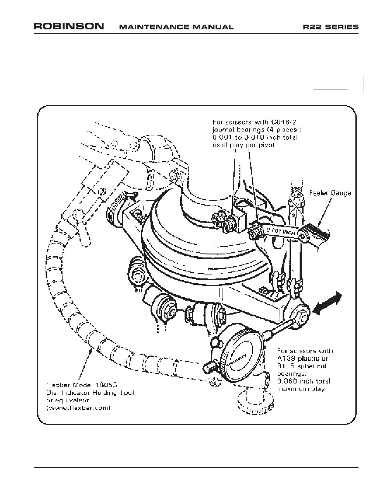
2.410 Inspection Procedures and Checklist (continued)
11. Open Mast Faring (11) (continued)
Main Rotor Drive Shaft: Inspect condition of accessible portion. Verify
no corrosion.
FIGURE 2-8 MEASURING UPPER SWASHPLATE SCISSORS PLAY
(Identify scissors bearing type and measure as shown)
OCT 2018
Chapter 2 Inspection
Page 2.35
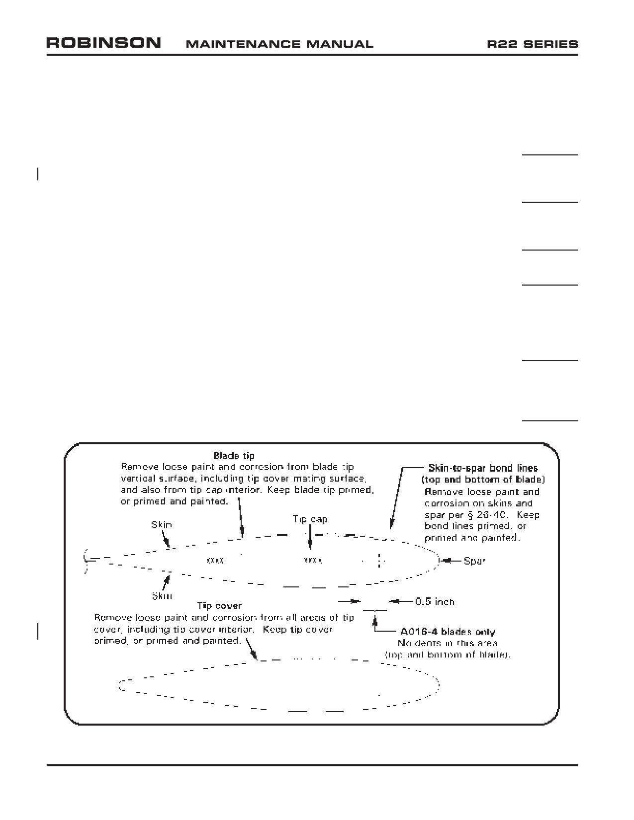
2.410 Inspection Procedures and Checklist (continued)
12. Rotor Hub and Hinge Bolts
Hub: Inspect condition. Verify no nicks, scratches, gouges, or corrosion.
If main rotor imbalance is suspected, check teeter and coning hinge friction
per § 26-32. Verify no brown or black residue (indicates bearing wear).
Hinge Bolts (three): Inspect condition; corrosion is prohibited. Verify cotter
pins are in place and secure. Verify bolt heads and nuts are torque striped
to thrust washers.
Pitch Links and Rod Ends: Inspect condition. Inspect rod ends per §
2.120, including centering. Verify security, including jam nut tightness and
proper safety wiring.
Fasteners & Torque Stripes: Inspect condition and verify security of all
fasteners. Renew deteriorated torque stripes per Figure 2-1.
13. Main Rotor Blades
Boots: Inspect condition. Verify no boot damage or oil leakage. Verify
proper boot position and security. Verify sufficient clearance from hub
assembly through full control travel.
Blade Spindles & Root Fittings: Inspect area for damage per § 26-43.
Comply with FAA Airworthiness Directive 88-26-01 (current revision) as
required (A158-1 spindles only). Verify proper installation and security of
visible fasteners. Renew deteriorated torque stripes per Figure 2-1.
FIGURE 2-9 MAIN ROTOR BLADE TIP AND TIP COVER
Page 2.36
Chapter 2 Inspection
OCT 2018
2.410 Inspection Procedures and Checklist (continued)
13. Main Rotor Blades (continued)
A016-6 Main Rotor Blade Inspection: Remove tip covers. Remove corrosion
and loose paint from tip covers, blade tips, and skin-to-spar bond lines. Epoxy
prime, or prime and paint, any exposed bare metal on tip covers, blade tips,
and skin-to-spar bond lines. Using an AN970-4 washer or 1965-or-later
U.S. quarter-dollar coin, tap-test critical bond areas and verify no dull or
hollow sounds. Visually inspect critical bond areas and verify no separation.
Install tip covers, ensuring cover edges are flush with blade profile.
A016-4 Main Rotor Blade Bond Inspection: Perform R22 SB-103A or
subsequent.
Main Rotor Blade Inspection: Inspect skins and doublers for scratches and
corrosion per § 26-41. Inspect blades for dents and local deformations
per § 26-42 and for voids per § 26-44. As required, wax blades with
soft cleaning cloths using carnauba-type wax (such as SC Johnson® Paste
Wax). Ensure tip cover and blade tip drain holes are unobstructed.
WARNING
Structural damage may occur if compressed air is applied to blade
tip drain holes.
14. Cabin
General: Verify no loose equipment that might interfere with controls.
Seat Belts: Inspect condition. Verify no fraying, broken stitching, holes,
or rotting. Verify no significant discoloration due to UV damage. Check
inertia reels for proper operation. Check buckles for proper operation.
Verify security.
NOTE
TSO tag not required on factory-installed harnesses.
Windows: Minor defects or imperfections that do not impair pilot's visibility
are considered acceptable. Acceptable defects include:
One nick, no more than 0.010 inch deep and no larger than 0.25 by
0.50 inch per square foot.
Scratches no more than 0.010 inch deep and 5 inches long.
Any surface defect such as small spots or stains that can be removed
with light polishing.
For cracks and crazing adjacent to windshield edges refer to § 25-20.
Yaw String: Inspect condition. Minimum 3 inches long each side. Verify
security.
OCT 2018
Chapter 2 Inspection
Page 2.37
2.410 Inspection Procedures and Checklist (continued)
14. Cabin (continued)
Exterior: Inspect condition. Verify no cracks, corrosion, or damage. Verify
no loose rivets. Loose rivets may be indicated by cracked paint and/or
black residue around heads.
Left and Right Navigation Lights: Inspect condition. Verify red left, green
right, lens cleanliness, and security.
Doors: Inspect condition. Verify no structural cracks around hinges or
door latches. Check door vents for operation. Ensure door hinge pins
are secured with cotter pins. Check tightness of hinge mounting screws.
Verify proper operation of door latching and locking mechanisms.
Fasteners & Torque Stripes: Inspect condition and verify security of all
fasteners. Renew deteriorated torque stripes per Figure 2-1.
15. Landing Gear
Skid Tubes and Shoes: Inspect condition. Verify no more than 0.5 inch
wide flat area on underside of skid tube due to wear. Verify longitudinal
scratches are not more than 0.030 inch deep, and circumferential scratches
are not more than 0.030 inch deep & are less than 0.50 inch long. Verify
drain holes are open (not applicable to float landing gear). Verify security
of rain caps. Verify minimum 0.05 inch shoe thickness.
Struts and Elbows: Inspect condition. Verify no cracks or corrosion,
especially where joined and in weld areas at bottom of struts. Verify
security. If helicopter routinely performs running landings, torque check
strut-to-skid-tube bolts.
Cross Tubes: Inspect condition. Verify minimum tail skid height per §
5.210. Verify no corrosion. Verify security of rain caps. If a rain cap is
loose, verify no internal corrosion. Verify no fretting at elbows.
Landing Gear Attach Points: Inspect condition. Verify no loose fasteners,
cracks, buckling, or fretting. Inspect mounts and verify no loose swages
or worn bearings.
Floats (if installed): Perform relief valve and bulkhead tests per § 2.580 (2)
and (3). Verify proper inflation pressure per R22 POH. Inspect condition.
Verify security.
Float Skid Tubes (if installed): Remove drain plugs at aft end of skid
extensions. With ground handling wheels installed, pull down on tailcone
to drain any trapped moisture. Install drain plugs.
Fasteners & Torque Stripes: Inspect condition and verify security of all
fasteners. Renew deteriorated torque stripes per Figure 2-1.
Page 2.38
Chapter 2 Inspection
OCT 2018
2.410 Inspection Procedures and Checklist (continued)
16. Life-Limited Parts, Additional Limitations, ADs, & SBs
Life-Limited Parts: Refer to helicopter maintenance records and § 3.300.
Replace life-limited parts as required. Verify components installed have
sufficient time remaining for projected operations.
Additional Component Maintenance: Refer to helicopter maintenance
records and § 1.102. Replace components scheduled for 12-year service,
overhaul, or replacement as required. Replace engine and accessories
scheduled for maintenance as required. Verify components installed have
sufficient time remaining for projected operations.
Airworthiness Directives: Verify applicable airframe, engine, and accessory
Airworthiness Directives (ADs) have been performed according to AD
compliance procedures. Some aircraft may be affected by ADs that require
recurring inspections at less than 100-hour or annual intervals. Recent
U.S. Airworthiness Directives are available online at www.faa.gov.
Service Bulletins: Verify applicable airframe, engine, and accessory Service
Bulletins (SBs) have been complied with according to manufacturers’
instructions. Some aircraft may be affected by SBs that require recurring
inspections at less than 100-hour or annual intervals. RHC Service Bulletins
17. Required Documents and Placards
Documents: Check that required documents (Airworthiness Certificate,
Registration, applicable Radio Station License, Pilot’s Operating Handbook,
Equipment List/Weight & Balance Data) are on board, legible, and current.
Placards: Verify required placards are properly installed, legible, and current.
Refer to Pilot’s Operating Handbook Section 2 for placard requirements.
18. Inspection and Access Covers
Foreign Objects Removed: Verify all tools, loose hardware, rags, and other
foreign objects are removed from helicopter.
Covers Closed and Secure: Install/close all inspection and access covers
removed in preceding steps. Verify security of all access covers.
Mariner Airbox Sealed: Ensure air box cover perimeter is sealed with
aluminum tape (Mariner models only).
OCT 2018
Chapter 2 Inspection
Page 2.39
2.410 Inspection Procedures and Checklist (continued)
19. Maintenance Records
Maintenance Records: Verify maintenance records are accurate, legible,
and complete. Enter maintenance performed (such as part replacement,
equipment adjustments, servicing, and lubrication) and inspection data.
Data must include a description of (or reference to data acceptable to the
Administrator) the work performed, date, helicopter total time in service,
signature, certificate type and certificate number of person approving
aircraft for return to service.
SHEAVE ALIGNMENT LEFT:
ENGINE HEIGHT:
SHEAVE ALIGNMENT RIGHT:
CLUTCH ANGLE:
TRDS RUNOUT:
CHECKLIST COMPLETE:
Mechanic’s signature:
Date:
Page 2.40
Chapter 2 Inspection
OCT 2018
2.590 Windshield Inspection
This section has been moved to § 25-20.
OCT 2018
Chapter 2 Inspection
Page 2.59
2.600 2200-Hour/12-Year Inspection
NOTE
KI-2202 (for R22-series Helicopter S/N 2570 & prior) and
KI-2203 (for R22-series Helicopter S/N 2571 & subsequent)
2200-Hour Inspection Kit contents are available online at www.
robinsonheli.com for review.
NOTE
12-Year Inspection is only required for helicopters that have
accumulated 12 years in service and less than 2200 hours time
in service since new, since last 2200-hour inspection, or since
last 12-year inspection.
1.
Refer to helicopter maintenance records and § 3.300; replace life-limited parts, or next
higher assemblies, as required.
2.
Refer to helicopter maintenance records and § 1.102; perform additional component
maintenance, as required.
3.
Remove engine, engine cooling panels, fanwheel, scroll, air induction system, carburetor
heat system, oil lines, and all hoses. Flush and pressure test oil cooler. Overhaul or
inspect, as required, magnetos, alternator, and carburetor per appropriate manufacturer’s
maintenance publications and service bulletins.
4.
Remove horizontal and vertical stabilizers per § 4.320, and replace as required. If
replacement is not required, visually inspect stabilizers and verify no cracks, corrosion,
loose rivets, dents, or deformation. Dye penetrant inspect any suspect areas per
§ 23-42. Install stabilizers per § 4.320.
5.
Remove landing gear assembly per § 5.100, and replace as required. If replacement is
not required, completely disassemble gear and remove paint. Visually inspect parts and
verify no cracks, corrosion, or deformation. Magnetic particle and fluorescent penetrant
inspect per §§ 23-41 and 23-42. Clean, prime, and paint per § 23-60. Assemble gear
if disassembled. Install landing gear assembly per § 5.100.
6.
Remove steel tube frames per § 4.200, and replace as required. If replacement is not
required, remove paint. Visually inspect frames and verify no cracks or corrosion.
Magnetic particle inspect per § 23-41. Clean, prime, and paint per § 23-60. Install
frames per § 4.200.
7.
Remove cyclic stick per § 8.110. Remove wiring harness. Remove paint via dry media
blasting. Visually inspect and verify no cracks or corrosion. Magnetic particle inspect
per § 23-41. Clean, prime, and paint per § 23-60. Install wiring harness. Install cyclic
stick per § 8.110.
Page 2.60
Chapter 2 Inspection
OCT 2018
2.600 2200-Hour/12-Year Inspection (continued)
8.
Remove A121 push-pull tube assemblies per § 8.160. Remove paint. Visually inspect
and verify no cracks or corrosion. Fluorescent penetrant inspect per § 23-42. Clean,
prime, and paint per § 23-60. Install push-pull tubes per § 8.160.
9.
Magnetic particle inspect A650 fittings and A337-1 jackshaft per § 23-41.
10.
Inspect airframe wiring condition. Verify no corrosion, insulation deterioration, or other
damage. Verify correct wires attached to correct circuit breakers.
11.
Remove main and aux tank fuel bladders per § 12.110 and § 12.120. Visually inspect.
Verify no corrosion, residue, microbial growth, or damage to fabric. Visually inspect
adjacent structure for evidence of bladder leakage. Replace roll-over vent valve o-rings
and packings per § 12.210. Remove any foreign object debris. Install bladders per
§ 12.110 and § 12.120.
12.
Perform clutch sheave alignment per § 7.230 and intermediate flex plate shimming per
§ 7.330.
13.
Perform main rotor flight control and blade angle rigging per § 10.110 and § 10.120.
14.
Perform tail rotor flight control and blade rigging per § 10.130 and § 10.140.
15.
Perform 100-hour/annual inspection per § 2.400.
16.
Weigh helicopter per § 18-20.
NOTE
Extended low-power operation with new piston rings may
prevent proper piston ring seating.
17.
Balance tail rotor per § 10.240. Track and balance main rotor per § 10.230. Perform
ground check, run up, and flight checks per §§ 2.205, 2.210, and 2.220.
18.
Drain and flush main and tail rotor gearboxes per § 22-13 and § 22-23.
19.
Make appropriate maintenance record entries. Enter maintenance performed (such as
part replacement, equipment adjustments, weighing, servicing, and lubrication) and
inspection data. Data must include a description of (or reference to data acceptable to
the Administrator) the work performed, date, helicopter total time in service, signature,
certificate type and certificate number of person approving aircraft return to service.
OCT 2018
Chapter 2 Inspection
Page 2.61
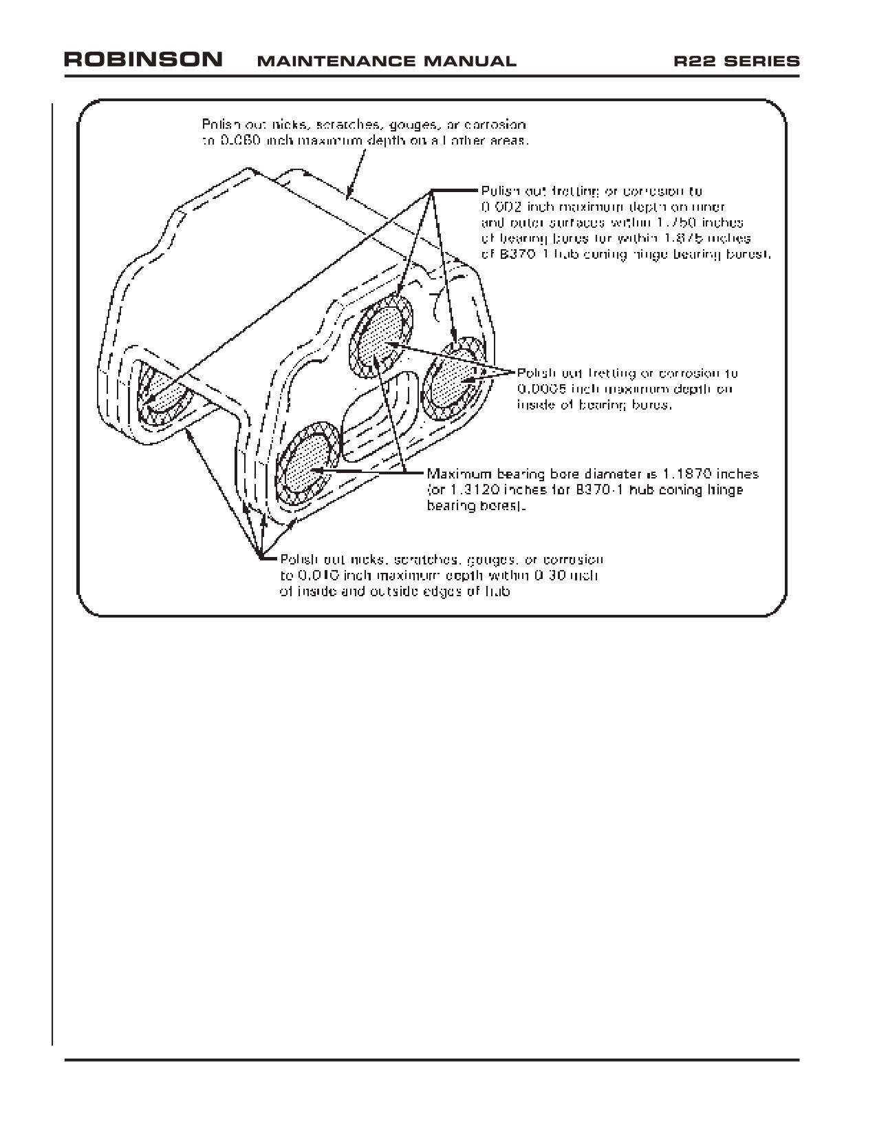
FIGURE 2-17 MAIN ROTOR HUB REPAIR LIMITS
2.610 Main Rotor Hub Inspection and Repair
1. Remove main rotor hub bearings per § 26-21 steps 1 and 2.
2. Remove hub paint by dry media blasting.
3. Refer to Figures 2-17 & 2-18. If required, polish surfaces using 320-grit or finer wet-
or-dry sandpaper to 0.25 inch minimum blend radius.
a. Visually inspect hub bearing bores and verify no scoring, scratches, or other obvious
damage. Polish out fretting or corrosion to 0.002 inch maximum depth on inner
and outer surfaces within 1.750 inches of bearing bores (or within 1.875 inches of
B370-1 hub coning hinge bearing bores). Polish out fretting or corrosion to 0.0005
inch maximum depth on inside of bearing bores; maximum bearing bore diameter
is 1.1870 inches (or 1.3120 inches for B370-1 hub coning hinge bearing bores).
b. Visually inspect all other areas of hub for obvious damage. Polish out nicks,
scratches, gouges, or corrosion to 0.010 inch maximum depth within 0.30 inch
of inside and outside edges of hub. Polish out nicks, scratches, gouges, or
corrosion to 0.060 inch maximum depth on all other areas.
Page 2.62
Chapter 2 Inspection
OCT 2018
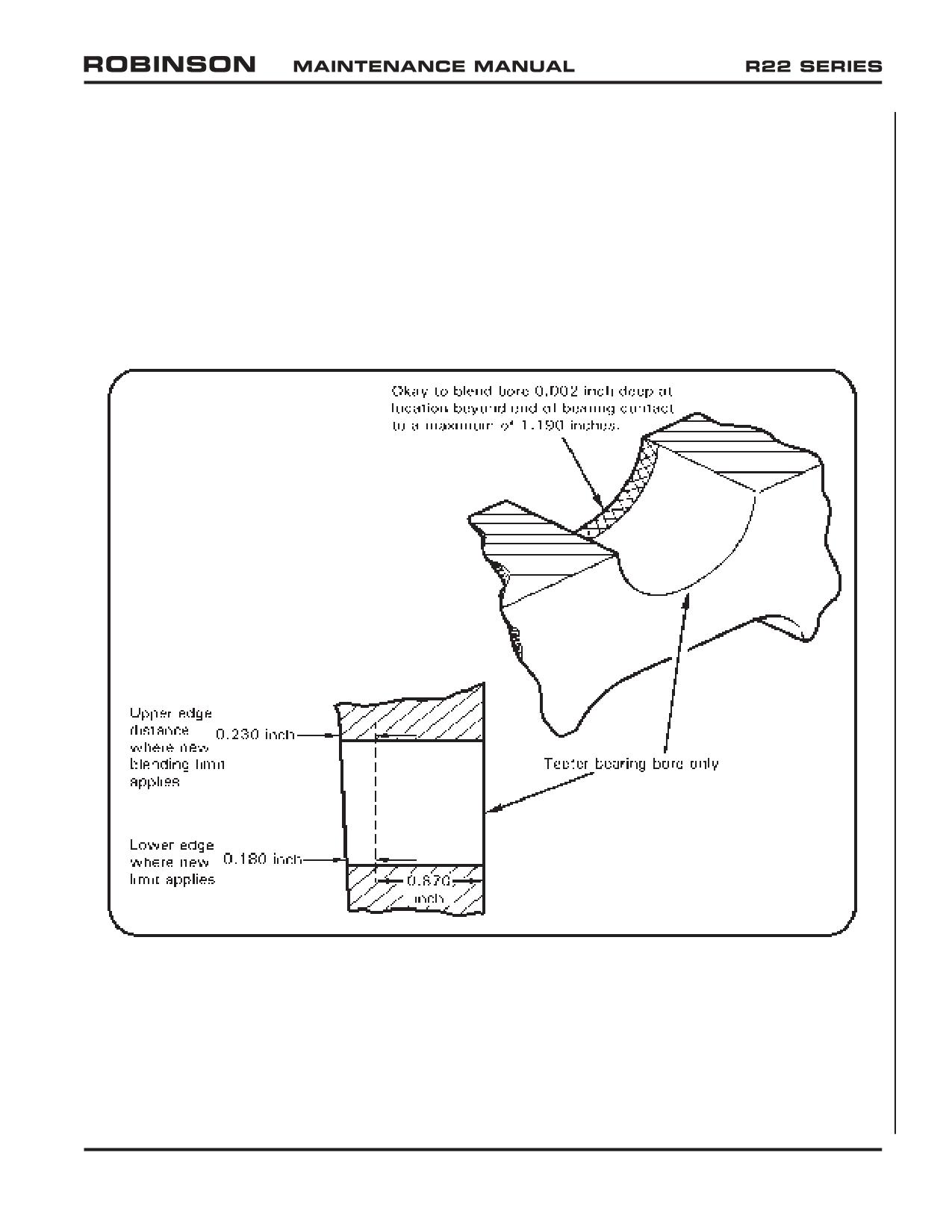
2.610 Main Rotor Hub Inspection and Repair (continued)
4. Fluorescent penetrant inspect hub per § 23-42.
5. Prime hub per § 23-60.
6. Install bearings per § 26-21 steps 4 and 5.
7. Mask bearings and topcoat hub assembly per § 23-60.
8. When top coat has sufficiently cured, remove masking.
FIGURE 2-18 MAIN ROTOR HUB REPAIR LIMITS
OCT 2018
Chapter 2 Inspection
Page 2.63
2.620 Tail Rotor Gearbox 12-Year Maintenance
1. If installed, drain and flush B021-1 tail rotor gearbox assembly per § 22-23 steps 1
thru 8.
2. If installed, remove tail rotor gearbox per § 7.410.
3. Remove hardware securing B546-1 yoke to B545 input gear. Visually inspect yoke
and replace yoke if damaged. Visually inspect input gear splines; return gearbox to
RHC if splines are damaged. Replace input shaft seal per § 7.470 steps 6 thru 17.
4. Remove sight gage and clean glass. Visually inspect gear set; return gearbox to RHC
if corrosion or other damage is detected. Install sight gage and special torque gage
per § 23-33.
5. Replace output shaft seal per § 7.460 steps 4 thru 9.
6. Install tail rotor gearbox per § 7.420 steps 1 thru 3.
7. Remove filler-plug. Fill gearbox to center of sight glass using A257-2 oil. Rotate rotor
system by hand for several revolutions and pull down on tail rotor gearbox several
times. Check gearbox oil level and adjust as required. Install filler-plug in gearbox and
special torque plug per § 23-33.
8. Connect tail light and chip detector wiring to airframe harness at connectors. Turn
battery on. Verify tail light illuminates with position lights turned on. Depress push-
to-test TR CHIP button and verify TR CHIP caution light illuminates. Turn battery off.
9. Install tail rotor per § 9.213.
Page 2.64
Chapter 2 Inspection
OCT 2018
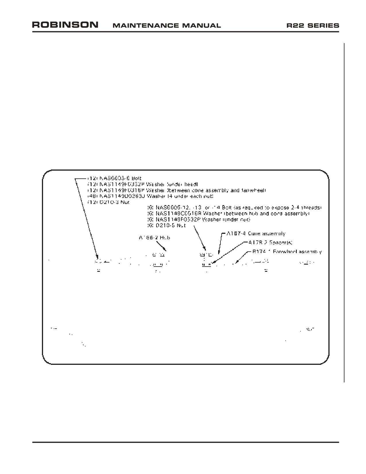
2.630 Fanwheel 12-Year Maintenance
1. If installed, remove B174-1 fanwheel assembly per § 6.210.
2. Mark fanwheel assembly parts, including balancing hardware, for identical reassembly.
3. Refer to Figure 2-19. Remove hardware securing A187-4 cone assembly, A186-2
hub, and A178-2 spacer(s) to fanwheel and remove parts, noting relative locations for
identical reassembly.
4. Visually inspect all components for obvious damage. Verify no elongation of fastener
holes. Replace parts as required.
5. Assemble fanwheel wet with epoxy primer (refer to § 23-70) between all clamping
surfaces; while primer is wet, special torque NAS6603 bolts to 70 in.-lb and NAS6605
bolts to 300 in.-lb.
FIGURE 2-19 B174-1 FANWHEEL ASSEMBLY
OCT 2018
Chapter 2 Inspection
Page 2.65
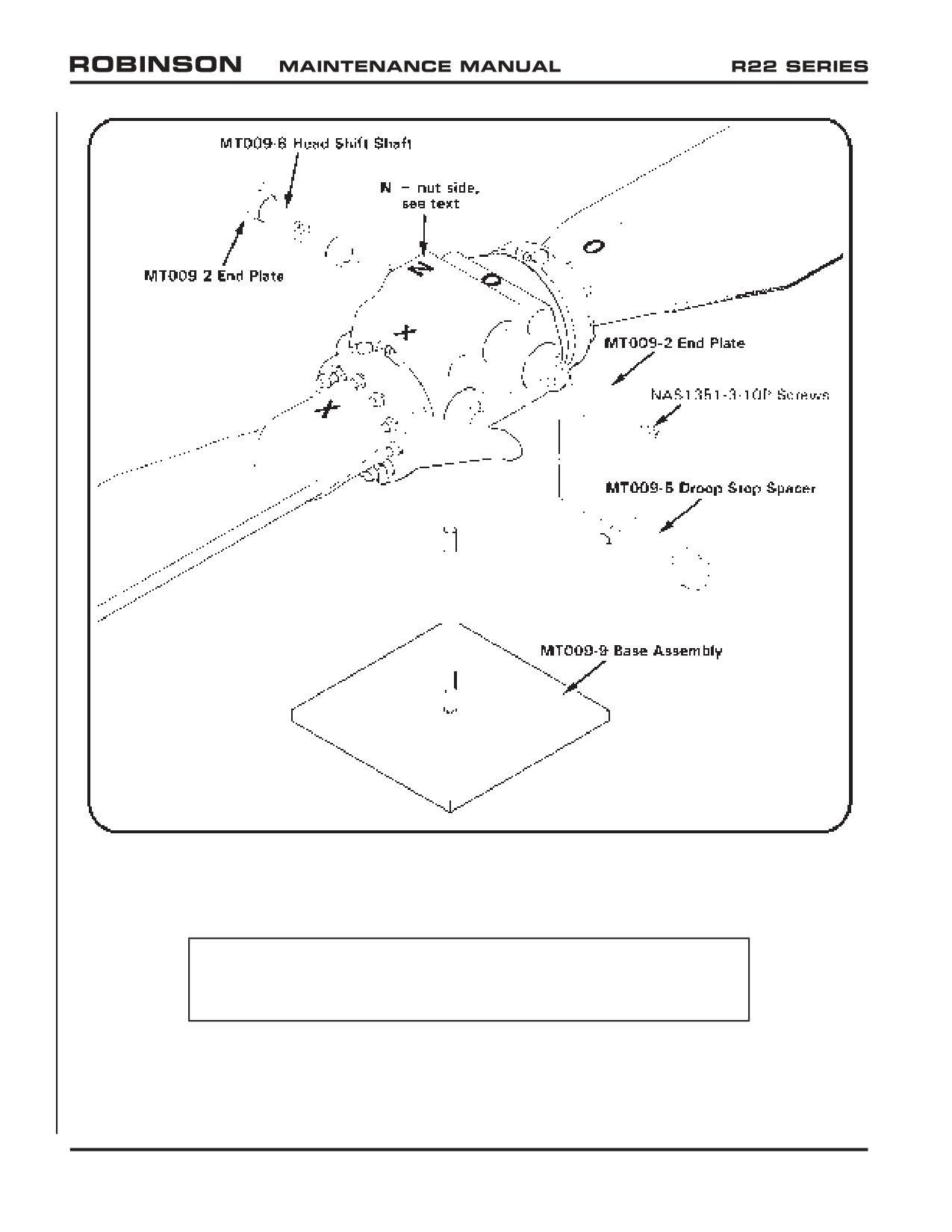
FIGURE 2-20 MT009-10 MAIN ROTOR STATIC BALANCE FIXTURE ASSEMBLY
2.640 Main Rotor Blade Static Balance
CAUTION
Ensure surfaces contacting blade skins and trailing edges are
sufficiently cushioned to prevent blade damage.
1. Refer to Table 26-1. Assemble main rotor blade & spindle assembly to main rotor
hub by selecting a combination of A106 coning hinge journals and A117 coning hinge
shims (if used) to obtain total axial clearance between 0.002-0.006 inch. Install
same length journal (dash number) on leading edge side of both coning hinges.
Page 2.66
Chapter 2 Inspection
OCT 2018
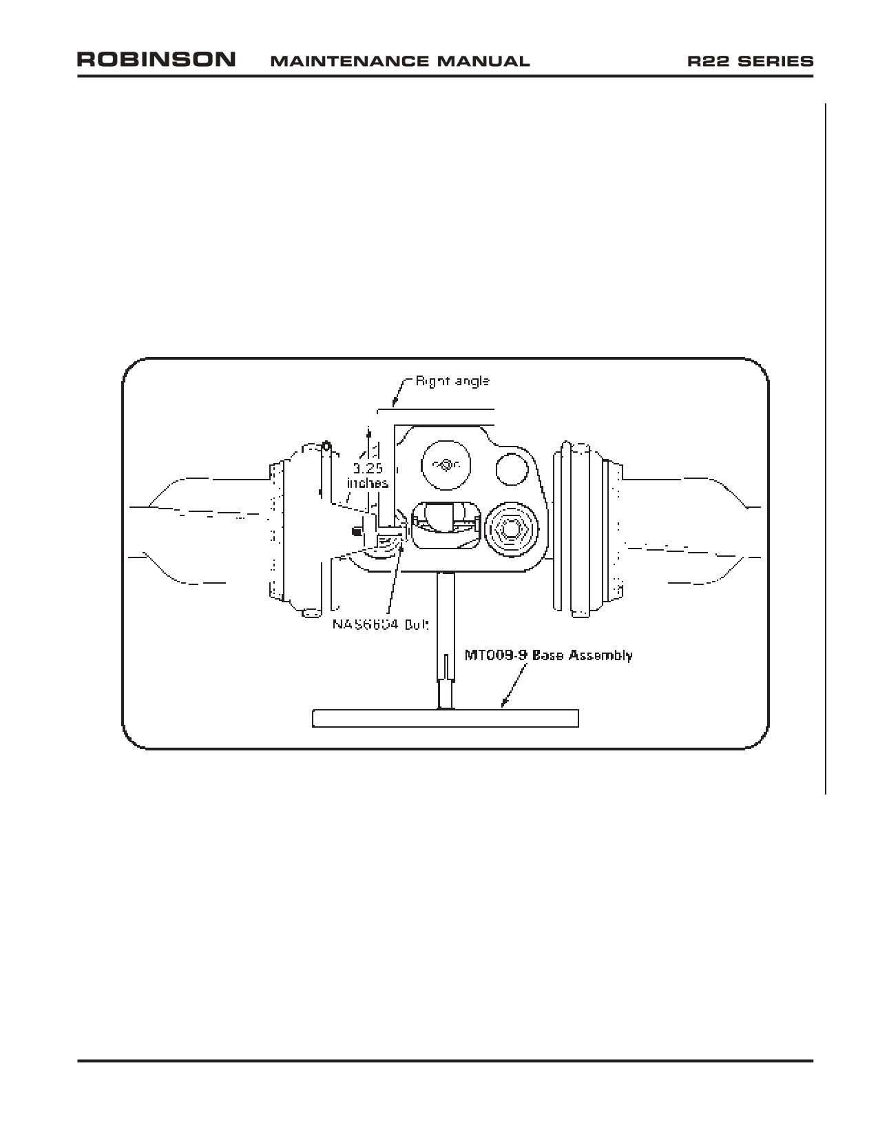
2.640 Main Rotor Blade Static Balance (continued)
2. Install nuts (dry); tighten nuts on hinge bolts until journals and thrust washers are
firmly seated (snug). Measure gaps between thrust washers and hub bearing faces per
Figure 26-8; verify total axial clearance at each hinge is between 0.002-0.006 inch.
3. Refer to Figure 2-20. Install MT009-10 main rotor static balancing fixture assembly in
hub as shown. Hoist main rotor assembly and position on MT009-9 base assembly.
4. Refer to Figure 2-21. Verify blade pitch angles are approximately equal.
5. Place a spirit level chordwise (parallel with teeter and coning hinges) atop main rotor
hub. Level by adjusting NAS1351-3-10P screws.
FIGURE 2-21 EQUALIZING BLADE PITCH
OCT 2018
Chapter 2 Inspection
Page 2.67
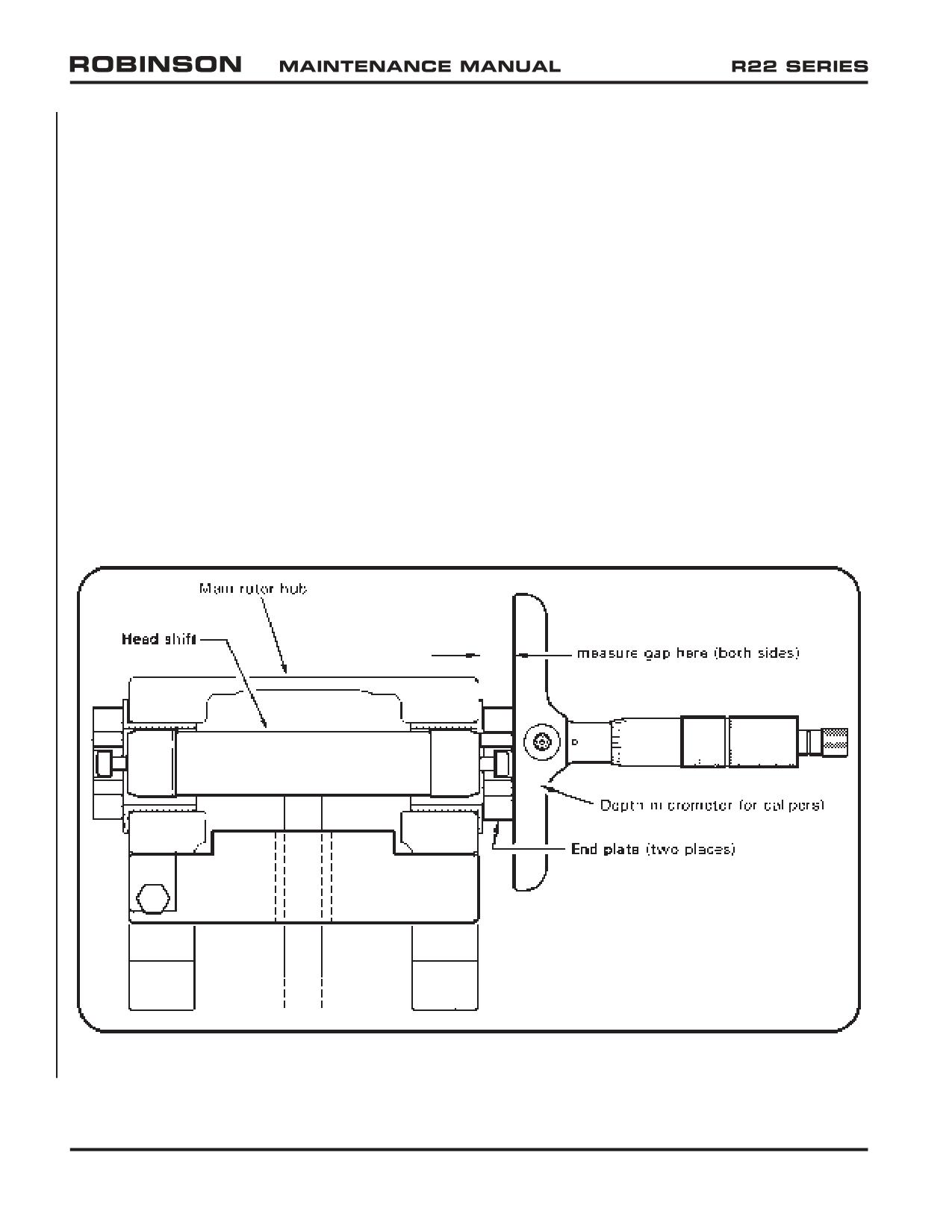
2.640 Main Rotor Blade Static Balance (continued)
6. Refer to Figure 2-22. Using a depth micrometer or calipers, measure distance between
MT009-2 end plate and MT009-8 shaft thru (either) end plate hole on both sides of
main rotor hub. On side of hub with smaller measured distance, mark top of hub with
letter “N” to indicate nut-side of teeter hinge bolt.
7. Place a spirit level spanwise (perpendicular to teeter and coning hinges) atop main
rotor hub. Place tip cover, tip cover attach screws, and two A722-4 screws as
close to blade tip as possible. Level rotor system by adding A298 balance strips,
NAS1149F0332P washers, and/or NAS1149F0363P washers as required. Final
balance to be within one NAS1149F0332P washer.
8. Apply light coat A257-9 anti-seize to threads and install screws securing tip weights
to blade; special torque screws to 40 in.-lb. Apply light coat A257-9 anti-seize
to threads and install screws securing tip cover to blade; special torque screws to
40 in.-lb. Recheck spanwise and chordwise balance.
9. Conspicuously mark rotor assembly with colored “X” and “O” on hub, blade roots,
and coning bolts (consistent marking on each side of hub) as reference for correct
assembly on helicopter. Disassemble main rotor assembly.
FIGURE 2-22 MEASURING GAP BETWEEN THRUST WASHER AND HUB BEARING
Page 2.68
Chapter 2 Inspection
OCT 2018
2.700 Additional Special Inspections
2.710 Volcanic Ash Recommendations
Flight in visible volcanic ash conditions (“ash cloud”) is detrimental to the helicopter and
should be avoided. If helicopter has been operated in visible volcanic ash conditions:
1.
Refer to Lycoming SI 1530. Wearing suitable protective equipment, use vacuum
cleaner followed by compressed air to remove as much debris as possible. Do not
use compressed air near main rotor blade drain holes.
2.
Refer to R22 Pilot’s Operating Handbook (POH) Section 8. Thoroughly clean, wash,
and rinse helicopter, including inner circumference of drive belts.
3.
Remove main rotor blade tip covers and clean blade tips.
4.
Using 10X magnification, visually inspect any exposed main rotor blade skin-to-
spar bond line (adhesive) for gaps (empty space between skin and spar). Blade is
unairworthy if any gap, including “pin hole(s)”, is detected in the bond line. Refinish
blade as required.
5.
Inspect condition of drive belt sheaves. Replace any sheave having corrosion pitting,
flaking, wear thru metalized or anodized coatings, roughness, or sharp ridges. Replace
drive belts if either sheave has sharp ridge(s) on drive belt contact surface.
6.
Disconnect alternator drive belt from alternator. Spin alternator pulley by hand and
verify rotor bearings and brushes operate smoothly; repair alternator as required if
roughness or unusual noise is encountered (volcanic ash can enter via unfiltered
cooling air). Inspect alternator and ring gear support pulleys and verify no wear
steps; replace alternator belt and pulley(s) if wear steps exist. Perform Lycoming
SI 1129 alternator belt tension check and adjust as required.
7.
Clean airbox interior and:
a. Inspect air filter and clean or replace as required.
b. Inspect induction system downstream of air filter (a clean, white glove is
beneficial). If volcanic ash is found then:
i. Clean induction system, disassembling as required.
ii. Disassemble carburetor or fuel injection servo, as applicable, inspect for
internal contamination, and overhaul as required.
iii. Perform Lycoming SI 1191 Cylinder Compression check.
iv. Perform Lycoming SB 388 Procedure to Determine Exhaust Valve and
Guide Condition.
v. Inspect spark plug condition; service as required.
OCT 2018
Chapter 2 Inspection
Page 2.69
2.710 Volcanic Ash Recommendations (continued)
8. Remove each magneto’s distributor gear inspection plug and inspect visible internal
portion for contamination; overhaul magnetos if volcanic ash is found inside (magneto
vent plugs are unfiltered).
9. Inspect engine oil condition. Regardless of oil time-in-service if oil smells bad, is opaque
(or is not obviously brown), or if particulates are detectable on the dipstick, change
engine oil & oil filter, inspect suction screen and old oil filter, and perform Lycoming
SI 1191 Cylinder Compression check if not previously accomplished in step 6.
2.720 Lightning Strike
Lightning strikes are extremely rare for helicopters operating in VFR conditions.
If a lightning strike does occur, RHC recommends performing a 100-hour inspection per
§ 2.400 and following recommendations for aircraft struck by lightning per Lycoming
Service Bulletin No. 401.
High voltage that is well conducted through the aircraft structure will dissipate and cause
minimal damage. High voltage that is not well conducted through the aircraft structure
can result in excessive heat, which can bake, burn, char, or even melt certain materials.
Heat damage may or may not be detectable by visual inspection. A component may not
exhibit obvious damage, but temperatures above 300º F can alter the strength of some
materials and thus affect a component's service life and airworthiness.
Visually inspect main rotor blades, landing gear, drive train, airframe, and flight controls
thoroughly for obvious damage such as electrical arcing or burns, pitting, or cracking.
Particular attention should be given to rod ends, journals, etc., where the conductive
path is most susceptible. If obvious damage is detected in any of the above-mentioned
systems, additional components may require replacement. Contact RHC Technical
Support with detailed documentation for further guidance prior to approving aircraft for
return to service.
Page 2.70
Chapter 2 Inspection
OCT 2018
CHAPTER 3
LIFE-LIMITED COMPONENTS
Section Title
Page
3.100
Life-Limited Components
3.1
3.110
Time-in-Service Records
3.1
3.120
Fatigue Life-Limited Parts
3.1
3.200
Type Certificate Data Sheet (TCDS)
3.2
3.300
Airworthiness Limitations
3.9
OCT 2018
Chapter 3 Life-Limited Components
Page 3.i
Intentionally Blank
Page 3.ii
Chapter 3 Life-Limited Components
OCT 2018
CHAPTER 3
LIFE-LIMITED COMPONENTS
3.100 Life-Limited Components
3.110 Time-In-Service Records
It is the operator’s responsibility to maintain a record of time in service for the airframe,
engine, and life-limited components. R22s are equipped with either an oil-pressure-
activated hourmeter which records engine run time or a collective-activated hourmeter
which records flight (collective up) time. Either method may be used to track time in
service, however numerical values for service lives depend on the tracking method used
(refer to § 3.300).
Calendar time in service for the airframe and engine begins on the date of the original RHC-
issued Export (or Standard) Certificate of Airworthiness for the helicopter. For spares
without a storage limit specified in § 23-85, calendar time in service begins on the date
of the RHC-issued Airworthiness Approval Tag (Authorized Release Certificate) issued
with the invoice.
If a component or an inspection is scheduled for hourly and calendar intervals, comply
with whichever requirement comes first, then reset interval unless otherwise specified.
When installing a life-limited part or a part with an overhaul requirement, record in the
helicopter maintenance record the installation date, part number, part name, serial number,
helicopter total time, and time in service accumulated by part since new or since last
overhaul, as applicable.
WARNING
Components with mandatory overhaul times or life limits whose
time in service is not reliably documented cannot be considered
airworthy and must be removed from service.
3.120 Fatigue Life-Limited Parts
The Airworthiness Limitations section lists the mandatory replacement schedule for
fatigue life-limited parts.
Listed items must be removed from the helicopter at the specified intervals and permanently
retired from service by destroying or damaging each part so it cannot inadvertently be
returned to service. Fatigue lives are based upon normal flight service, including 6 rotor
stop-starts and 10 autorotation entries per hour.
OCT 2018
Chapter 3 Life-Limited Components
Page 3.1
3.200 Type Certificate Data Sheet (TCDS)
The Robinson R22-series Type Certficate Data Sheet (TCDS) reprinted on the following
pages is subject to revision.
Visit the FAA Aircraft Certification Regulatory and Guidance Library online databases to
determine TCDS revision status at: http://rgl.faa.gov.
Page 3.2
Chapter 3 Life-Limited Components
OCT 2018
DEPARTMENT OF TRANSPORTATION
FEDERAL AVIATION ADMINISTRATION
H10WE
REVISION 16
ROBINSON
R22
R22 ALPHA
R22 BETA
R22 MARINER
June 28, 2018
TYPE CERTIFICATE DATA SHEET NO. H10WE
This data sheet, which is a part of Type Certificate No. H10WE, prescribes conditions and limitations under which the product
for which the type certificate was issued meets the airworthiness requirements of Title 14 of the Code of Federal Regulations.
Type Certificate Holder:
Robinson Helicopter Company
2901 Airport Drive
Torrance, California 90505
I. Model R22 Helicopter (Normal Category), Approved March 16, 1979
Engine
Lycoming O-320-A2B or O-320-A2C or
O-320-B2C (See NOTES 5 & 6)
Fuel
See Rotorcraft Flight Manual (RFM)
Engine Limits for all operations
124 hp at 2652 rpm (104%)
See RFM for manifold pressure limit corresponding to 124 hp and ambient
conditions.
Rotor Limits
Power Off (Rotor Tach)
Power On (Rotor Tach)
Maximum (110%) 561 rpm
(104%) 530 rpm
Minimum (90%) 459 rpm
(97%) 495 rpm
Airspeed Limits (CAS)
98 KCAS Power On and Off VNE (never exceed) at sea level.
See RFM for reduction of VNE with altitude and temperature.
Altitude Limits
Density Altitude Limit - 14,000 feet
CG Range
See RFM
Maximum Gross Weight
1300 lbs.
No. Seats
2 (See NOTE 1)
Minimum Weight
920 lbs.
Maximum Baggage
50 pounds of baggage and installed equipment in either baggage compartment,
except combined seat load plus baggage and equipment not to exceed 240 pounds.
Page No.
1
2
3
4
5
6
Rev. No.
16
16
16
16
16
16
OCT 2018
Chapter 3 Life-Limited Components
Page 3.3
H10WE
Page 2 of 6
I. Model R22 Helicopter (Normal Category), Approved March 16, 1979, (cont'd)
Fuel Capacity
Tanks Without Bladders
Tanks With Bladders
Location
Tank
Capacity
Usable
Capacity
Usable
(STA)
(gal.)
(gal.)
(gal.)
(gal.)
Main
19.8
19.2
18.3
16.9
108.6
Auxiliary
N/A
N/A
9.7
9.4
103.8
Oil Capacity
Engine Oil, 6 qt. at STA 104.8;
Transmission oil, 1.2 qt. at STA 100.
Rotor Blade and Control Movements
For rigging information refer to R22 Maintenance Manual
Serial Nos. Eligible
0002 thru 0300
0302 thru 0349
0352 thru 0356
II. Model R22 ALPHA Helicopter (Normal Category), Approved October 12, 1983
Engine
Lycoming O-320-B2C
Fuel
See RFM
Engine Limits for all operations
124 hp at 2652 rpm (104%)
See RFM for manifold pressure limit corresponding to
124 hp and ambient
conditions.
Rotor Limits
Power Off (Rotor Tach)
Power On (Rotor Tach)
Maximum (110%) 561 rpm
(104%) 530 rpm
Minimum (90%) 459 rpm
(97%) 495 rpm
Airspeed Limits
98 KCAS Power On and Off VNE (never exceed) at sea level.
See RFM for reduction of VNE with altitude and temperature.
Altitude Limits
Density Altitude Limit - 14,000 feet
CG Range
See RFM
Maximum Gross Weight
1370 lbs.
No. Seats
2 (Pilot Location STA 78.0)
Minimum Weight
920 lbs.
Maximum Baggage
50 pounds of baggage and installed equipment in either baggage compartment,
except combined seat load plus baggage and equipment not to exceed 240 pounds.
Fuel Capacity
Tanks Without Bladders
Tanks With Bladders
Location
Tank
Capacity
Usable
Capacity
Usable
(STA)
(gal.)
(gal.)
(gal.)
(gal.)
Main
19.8
19.2
18.3
16.9
108.6
Auxiliary
10.9
10.5
9.7
9.4
103.8
Oil Capacity
Engine oil, 6 qt. at STA 104.8;
Transmission oil, 1.2 qt. at STA 100.
Rotor Blade and Control Movements
For rigging information refer to R22 Maintenance Manual.
Serial Nos. Eligible
0301, 0350, 0351, 0357 thru 0500, excluding 0364
Page 3.4
Chapter 3 Life-Limited Components
OCT 2018
H10WE
Page 3 of 6
III. Model R22 BETA Helicopter (Normal Category), Approved August 12, 1985
The R22 BETA Helicopter includes a 131 hp. takeoff rating. A larger oil cooler and associated installation changes were made to
permit the 131 hp. takeoff rating with the O-320 engine.
Engine
Lycoming O-320-B2C or O-360-J2A (See NOTE 11)
Fuel
See RFM
Engine Limits for all operations
Maximum continuous:
124 hp at 2652 rpm (104%)
Takeoff (5 minutes):
131 hp at 2652 rpm (104%)
See RFM for manifold pressure limit corresponding to hp. rating and ambient
conditions.
Rotor Limits
Power Off (Rotor Tach) for
Power On (Rotor
Power On (Rotor Tach)
O-320-B2C and O-360-J2A
Tach) for O-320-B2C
for O-360-J2A
Maximum (110%) 561 rpm
(104%) 530 rpm
(104%) 530 rpm
Minimum (90%) 459 rpm
(97%) 495 rpm
(101%) 515 rpm
Airspeed Limits (CAS)
98 KCAS Power On and Off VNE (never exceed) at sea level.
See RFM for reduction of VNE with altitude and temperature.
Altitude Limits
Density Altitude Limit - 14,000 feet
CG Range
See RFM
Maximum Gross Weight
1370 lbs.
No. Seats
2 (Pilot Location STA 78.0)
Minimum Weight
920 lbs.
Maximum Baggage
50 pounds of baggage and installed equipment in either baggage compartment,
except combined seat load plus baggage and equipment not to exceed 240 pounds.
Fuel Capacity
Tanks Without Bladders
Tanks With Bladders
Location
Tank
Capacity
Usable
Capacity
Usable
(STA)
(gal.)
(gal.)
(gal.)
(gal.)
Main
19.8
19.2
18.3
16.9
108.6
Auxiliary
10.9
10.5
9.7
9.4
103.8
Oil Capacity
Engine oil, 6 qt. at STA 104.8;
Transmission oil, 1.2 qt. at STA 100.
Rotor Blade and Control Movements
For rigging information refer to R22 Maintenance Manual.
Serial Nos. Eligible
0501 and subsequent
OCT 2018
Chapter 3 Life-Limited Components
Page 3.5
H10WE
Page 4 of 6
IV. Model R22 MARINER Helicopter (Normal Category), Approved September 12, 1985
The R22 MARINER helicopter includes two inflatable floats, additional corrosion protection, 131 hp. takeoff rating, tailcone
with nose-up horizontal stabilizer mounting angle and float stabilizer in place of the tail skid. The helicopter can be used with or
without floats. (See NOTE 9)
Engine
Lycoming O-320-B2C or O-360-J2A (See NOTE 11)
Fuel
See RFM
Engine Limits for all operations
Maximum continuous:
124 hp at 2652 rpm (104%)
Takeoff (5 minutes):
131 hp at 2652 rpm (104%)
See RFM for manifold pressure limit corresponding to hp. rating and ambient
conditions.
Rotor Limits
Power Off (Rotor Tach) for
Power On (Rotor
Power On (Rotor Tach)
O-320-B2C and O-360-J2A
Tach) for O-320-B2C
for O-360-J2A
Maximum (110%) 561 rpm
(104%) 530 rpm
(104%) 530 rpm
Minimum (90%) 459 rpm
(97%) 495 rpm
(101%) 515 rpm
Airspeed Limits (CAS)
With Floats Installed
91 KCAS Power On VNE (never exceed) at sea level.
77 KCAS Power Off VNE (never exceed) at sea level.
See RFM for reduction of VNE with altitude and temperature.
Without Floats Installed
98 KCAS Power On and Off VNE (never exceed) at sea level.
See RFM for reduction of VNE with altitude and temperature.
Altitude Limits
Density Altitude Limit - 14,000 feet
CG Range
See RFM
Maximum Gross Weight
1370 pounds
No. Seats
2 (Pilot Location STA 78.0)
Minimum Weight
920 pounds
Maximum Baggage
50 pounds of baggage and installed equipment in either baggage compartment,
except combined seat load, plus baggage and equipment not to exceed 240 pounds.
Fuel Capacity
Tanks Without Bladders
Tanks With Bladders
Location
Tank
Capacity
Usable
Capacity
Usable
(STA)
(gal.)
(gal.)
(gal.)
(gal.)
Main
19.8
19.2
18.3
16.9
108.6
Auxiliary
10.9
10.5
9.7
9.4
103.8
Oil Capacity
Engine oil, 6 qt. at STA 104.8;
Transmission oil, 1.2 qt. at STA 100.
Rotor Blade and
For rigging information refer to R22 Maintenance Manual.
Control Movements
Serial No. Eligible
0364, 0501 and subsequent (Suffix "M" added to all MARINERs.)
Page 3.6
Chapter 3 Life-Limited Components
OCT 2018
H10WE
Page 5 of 6
DATA PERTINENT TO ALL MODELS
Datum
100 inches forward of main rotor centerline.
Leveling Means
Refer to the Weight and Balance Section of the R22 Rotorcraft Flight Manual.
Certification Basis
14 CFR Part 27 dated February 1, 1965, including Amendments 27-1 through 27-10.
§ 27.1559 of Amendment 27-21 is an option for all S/Ns.
National Environmental Act of 1969
Noise Control Act of 1972
Equivalent Safety Finding:
Number TD10352LA-R/S-1
14 CFR Part 27.1401(d), Anticollision Light System
Production Basis
Production Certificate No. 424WE, dated March 6, 1981
Equipment
The basic required equipment as prescribed in the applicable airworthiness
regulations (See Certification Basis) must be installed in the helicopter for
certification. In addition, the following FAA-approved Rotorcraft Flight
Manual is
required:
R22
R22 Rotorcraft Flight Manual dated March 16, 1979, or later revision.
R22 ALPHA
R22 Rotorcraft Flight Manual dated March 16, 1979, with revisions through October
12, 1983 or later (see NOTE 8).
R22 BETA with O-320-B2C
R22 Rotorcraft Flight Manual dated March 16, 1979, with revisions through August
7, 1985 or later (see NOTE 8).
R22 BETA with O-360-J2A
R22 Rotorcraft Flight Manual dated March 16, 1979,with revisions through August
7, 1985 or later. For R22 Rotorcraft Flight Manual with revisions prior to October
13, 2000, Flight Manual Supplement 7 dated January 31, 1996, or later revision, is
required (see NOTE 8).
R22 MARINER with O-320-B2C
R22 Rotorcraft Flight Manual dated March 16, 1979, with revisions through August
7, 1985 or later, and Flight Manual Supplement 4 dated September 9, 1985, or later
revision.
R22 MARINER with O-360-J2A
R22 Rotorcraft Flight Manual dated March 16, 1979, with revisions through August
7, 1985 or later, and Flight Manual Supplement 4 dated September 9, 1985, with
revisions through October 13, 2000 or later. For R22 Rotorcraft Flight Manual with
revisions prior to October 13, 2000, Flight Manual Supplement 8 dated January 31,
1996, or later revision, is required in place of Flight Manual Supplement 4.
ALL MODELS
If fuel tanks with bladders are installed: R22 Rotorcraft Flight Manual dated March
16, 1979, with revisions through February 15, 2013 or later. R22 Mariners also
require Flight Manual Supplement 4 as noted above. Also see Note 8.
OCT 2018
Chapter 3 Life-Limited Components
Page 3.7
H10WE
Page 6 of 6
GENERAL NOTES
NOTE 1.
Current weight and balance report, including list of equipment included in certificated empty weight , and loading
instructions, when necessary, must be provided for each helicopter at the time of original certification and at all
times thereafter (except in the case of operators having an approved weight control system).
Pilot Location STA 79.0 for helicopter S/Ns 0002 thru 0255 and STA 78.0 for helicopter S/Ns 0256 and
subsequent and helicopters in which Robinson P/N seats A466-1 and A467-1 have been replaced by Robinson
P/N seats A932-1 and A928-1.
NOTE 2.
One of the following placards must be installed in clear view of the pilot:
"THE MARKINGS AND PLACARDS INSTALLED ON THIS HELICOPTER CONTAIN
OPERATING LIMITATIONS WHICH MUST BE COMPLIED WITH WHEN OPERATING THIS
ROTORCRAFT. OTHER OPERATING LIMITATIONS WHICH MUST BE COMPLIED WITH WHEN
OPERATING THIS ROTORCRAFT ARE CONTAINED IN THE ROTORCRAFT FLIGHT MANUAL."
Or: "THIS ROTORCRAFT APPROVED FOR DAY AND NIGHT VFR OPERATIONS"
For the R22 MARINER:
"THIS ROTORCRAFT APPROVED FOR DAY AND NIGHT VFR OPERATIONS WITHOUT
FLOATS INSTALLED OR DAY VFR OPERATIONS ONLY WITH FLOATS INSTALLED."
For additional placards, see R22 Rotorcraft Flight Manual.
NOTE 3.
Information essential to the proper maintenance of the helicopter, including retirement time of critical
components, is contained in the Robinson R22 Maintenance Manual and Instructions For Continued Airworthiness
(RTR 060). Retirement times are listed in the "AIRWORTHINESS LIMITATIONS" section.
NOTE 4.
Deleted as of April 11, 1988.
NOTE 5.
Lycoming O-320-A2C, with Retard Magneto Starting System, eligible on S/Ns 0002 thru 0300, 0302 thru 0349,
and 0352 thru 0356 helicopters.
NOTE 6.
Lycoming O-320-B2C installed on S/Ns 0175 and 0200 thru 2570 in production. It may be installed in prior
S/N helicopters if the following parts are changed; Robinson P/Ns B193-2 (Window Plate - Instrument Cluster),
A145-3 (Engine), A600-2 (Manifold Pressure Gauge), and A654-40 & -41 (Decals).
NOTE 7.
Deleted as of April 25, 2001.
NOTE 8.
The R22 "Police Helicopter" configuration requires Flight Manual Supplement 3, dated March 27, 1984 or later.
NOTE 9.
The R22 MARINER with floats installed is limited to daylight VFR operation only.
NOTE 10.
R22 ALPHA S/N 0364 was converted to an R22 MARINER by the manufacturer. The original R22 ALPHA
dataplate was removed and replaced with an R22 MARINER data plate S/N 0364M.
NOTE 11.
Lycoming O-360-J2A installed on S/N 2571 and subsequent in production. Retrofit installation of the O-360-J2A
engines may only be accomplished at the Robinson Helicopter Company.
NOTE 12.
Deleted as of May 24, 2018.
.....END
Page 3.8
Chapter 3 Life-Limited Components
OCT 2018
3.300 Airworthiness Limitations
The Airworthiness Limitations Section is FAA approved and specifies inspections and other
maintenance required under 14 CFR §§ 43.16 and 91.403, unless an alternative program
has been FAA approved.
Time in service may be tracked based on engine run time or based on flight (collective up)
time. Either method may be used, however numerical values for service lives depend on
the tracking method used.
R22 Fatigue Life-Limited Parts
Use the following lives if time is tracked based on engine run time as recorded by an
oil-pressure-activated hourmeter:
Part Number
Description
Maximum Service Life
A016-2 (Retired by AD 2004-19-09) . . Main Rotor Blade
2200 Hours or 10 years1
A016-4 and -6
Main Rotor Blade
2200 Hours or 12 years1
A029-1 and -2
Tail Rotor Blade
2200 Hours or 12 years1
A146-1
Pinion, Main Gearbox
2200 Hours
(O-360 Engine)
A158-3
Main Rotor Spindle
2200 Hours
B545-1
Gear Set, Tail Gearbox
2200 Hours
B545-2
Pinion, Tail Gearbox
2200 Hours
NAS630-80 (or MS21250-10080) . . . Coning Hinge Bolt
2200 Hours
NAS1351-4-20 (or A722-1 or -2)
Pitch Horn Screws
2200 Hours
NAS6604 (or NAS1304)
Tail Rotor Blade-to-Hub Attach Bolt . . .
2200 Hours
A158-1
Main Rotor Spindle
2415 Hours2
A020-2
Upper Frame, Rev R & Prior
4200 Hours
A020-2 and -90
Upper Frame, Rev S & Subsequent
4400 Hours
A023-1, -20, -22, and -23
Tailcone Assembly
4400 Hours
A047-1 and -6
Upper Frame
4400 Hours
A154-1
Main Rotor Hub
4400 Hours
B370-1
Main Rotor Hub
4400 Hours
A020-84
Lower R.H. Frame
5110 Hours
A046-2
Lower R.H. Frame
5110 Hours
A062-2
Tail Rotor Hub
6000 Hours
A030-1
Tail Rotor Hub Assembly
6260 Hours
1
Whichever limit occurs first. Calendar time starts on date of original RHC-issued Airworthiness Approval.
2
Subject to AD 88-26-01 R2 compliance.
OCT 2018
Chapter 3 Life-Limited Components
Page 3.9
3.300 Airworthiness Limitations (continued)
R22 Fatigue Life-Limited Parts (continued)
Use the following lives if time is tracked based on flight (collective up) time as recorded
by a collective-activated hourmeter:
Part Number
Description
Maximum Service Life
A016-2 (Retired by AD 2004-19-09) . .
Main Rotor Blade
1964 Hours or 10 years1
A016-4
Main Rotor Blade
1964 Hours or 12 years1
NAS630-80 (or MS21250-10080) . . .
Coning Hinge Bolt
1964 Hours
NAS1351-4-20 (or A722-1 or -2)
Pitch Horn Screws
1964 Hours
A158-1
Main Rotor Spindle
2156 Hours2
A016-6
Main Rotor Blade
2200 Hours or 12 years1
A029-1 and -2
Tail Rotor Blade
2200 Hours or 12 years1
A146-1
Pinion, Main Gearbox
2200 Hours
A158-3
Main Rotor Spindle
2200 Hours
A188-2
Sprag Clutch Assembly
2200 Hours
A647-1
Bearing, Main Rotor Shaft
2200 Hours or 12 years1
A647-6
Bearing, Tail Rotor Pitch Control
2200 Hours or 12 years1
A647-8
Bearing, Damper Assembly
2200 Hours or 12 years1
B545-1
Gear Set, Tail Gearbox
2200 Hours
B545-2
Pinion, Tail Gearbox
2200 Hours
NAS6604 (or NAS1304)
Tail Rotor Blade-to-Hub Attach Bolt . . .
2200 Hours
A020-2
Upper Frame, Rev R & Prior
3750 Hours
A154-1
Main Rotor Hub
3928 Hours
A020-2 and -90
Upper Frame, Rev S & Subsequent
4400 Hours
A020-84
Lower R.H. Frame
4400 Hours
A023-1, -20, -22, and -23
Tailcone Assembly
4400 Hours
A046-2
Lower R.H. Frame
4400 Hours
A047-1 and -6
Upper Frame
4400 Hours
A062-2
Tail Rotor Hub
4400 Hours
B370-1
Main Rotor Hub
4400 Hours
A030-1
Tail Rotor Hub Assembly
5589 Hours
1 Whichever limit occurs first. Calendar time starts on date of original RHC-issued Airworthiness Approval.
2 Subject to AD 88-26-01 R2 compliance.
Approved By:
Date:
Manager, Federal Aviation Administration
Los Angeles ACO Branch, AIR-790
FAA Approved: This and the previous page constitute the Airworthiness Limitations Section
in its entirety, are considered segregated from the rest of the document, and set forth the
FAA-approved mandatory replacement times for fatigue life-limited parts.
Page 3.10
Chapter 3 Life-Limited Components
OCT 2018
CHAPTER 4
AIRFRAME
Section Title
Page
4.000
Description
4.1
4.100
Fuselage
4.1
4.110
Cabin Assembly
4.1
4.111
Repair
4.1
4.120
Windshield Assembly
4.4
4.130
Door Removal and Installation
4.4
4.140
Fairing, Cowling, and Inspection Panels
4.4
4.141
Side Skirts
4.4
4.142
Mast Fairing
4.6
4.143
Aft Cowling
4.6
4.144
Cabin Inspection Panels
4.6
4.200
Welded Steel Tube Frame Assemblies
4.7
4.210
Left-Hand Frame Assembly
4.8
4.211
Left-Hand Frame Removal
4.8
4.212
Left-Hand Frame Installation
4.8
4.220
Right-Hand Frame Assembly
4.9
4.221
Right-Hand Frame Removal
4.9
4.222
Right-Hand Frame Installation
4.12
4.230
Upper Frame Assembly
4.13
4.231
Upper Frame Removal
4.13
4.232
Upper Frame Installation
4.14
4.240
Strut Assembly Removal and Installation
4.15
4.300
Tailcone and Empennage
4.16
4.310
Tailcone
4.16
4.311
Tailcone Removal
4.16
4.312
Tailcone Installation
4.16
4.313
Tailcone Replacement
4.17
4.314
Tailcone Repair
4.22
4.320
Empennage Assembly
4.22
4.321
Empennage Removal
4.22
4.322
Empennage Installation
4.23
4.323
Upper Stabilizer Replacement
4.23
4.324
Lower Stabilizer Replacement
4.23
4.325
Horizontal Stabilizer Replacement
4.24
OCT 2018
Chapter 4 Airframe
Page 4.i
Intentionally Blank
Page 4.ii
Chapter 4 Airframe
OCT 2018
CHAPTER 4
AIRFRAME
4.000 Description
The R22 is a two-place, single main rotor, single engine helicopter constructed primarily of
metal and equipped with skid-type landing gear.
The primary fuselage structure is welded steel tubing and riveted aluminum sheet. The
tailcone is a monocoque structure in which aluminum skins carry primary loads. Fiberglass
and thermoplastics are used in secondary cabin structure, engine cooling shrouds, and
various other ducts and fairings.
A right-side cowl door provides access to the main gearbox and drive system. Additional
access to controls and other components for maintenance is provided by removable panels
and cowlings.
Stainless steel firewalls are located forward of and above the engine.
4.100 Fuselage
4.110 Cabin Assembly
The cabin assembly is a non-field-replaceable assembly.
4.111 Repair
1. Vertical firewall replacement must be performed at the factory in a jig. Firewall repairs
may be accomplished in accordance with U.S. FAA Advisory Circular 43.13-1B
Section 4-59. Firewall material is 0.016 inch, type 301, one-quarter hard corrosion-
resistant (CRES) steel.
2. Keel panel replacement must be performed at the factory in a jig. Keel panel repairs
may be accomplished in accordance with U.S. FAA Advisory Circular 43.13-1B
Sections 4-58 and 4-59. Keel panel material is 0.025 inch, 2024-T3 clad aluminum-
alloy sheet.
3. To preserve crashworthiness, repairs to seat structure are limited to replacement of
damaged components only.
OCT 2018
Chapter 4 Airframe
Page 4.1
Intentionally Blank
Page 4.2
Chapter 4 Airframe
OCT 2018
Intentionally Blank
OCT 2018
Chapter 4 Airframe
Page 4.3
4.120 Windshield Assembly
This section has been moved to Chapter 25 Doors and Windows.
4.130 Door Removal and Installation
This section has been moved to Chapter 25 Doors and Windows.
4.140 Fairing, Cowling, and Inspection Panels
4.141 Side Skirts
CAUTION
This is a structural panel assembly and must be installed for run
up and flight.
Page 4.4
Chapter 4 Airframe
OCT 2018
CHAPTER 5
LANDING GEAR
Section Title
Page
5.000
Landing Gear
5.1
5.001
Introduction
5.1
5.002
Description
5.1
5.100
Landing Gear Assembly
5.2
5.110
Landing Gear Removal
5.2
5.120
Landing Gear Installation
5.2
5.200
Cross Tubes
5.3
5.210
Cross Tube Removal
5.3
5.220
Cross Tube Installation
5.4
5.300
Skid Tubes
5.4
5.310
Skid Tube Removal
5.4
5.320
Skid Tube Installation
5.4
5.330
Skid Shoe Removal and Replacement
5.4
5.340
Ground Handling Wheel Support Removal and Replacement
5.8
5.400
Preventive Maintenance
5.8
5.500
Float Ship Landing Gear
5.9
5.510
Float Landing Gear Removal
5.9
5.520
Float Landing Gear Installation
5.10
5.530
Float Tube Removal
5.11
5.540
Float Tube Installation
5.11
5.550
Float Tube Repair
5.13
OCT 2018
Chapter 5 Landing Gear
Page 5.i
Intentionally Blank
Page 5.ii
Chapter 5 Landing Gear
OCT 2018
CHAPTER 5
LANDING GEAR
5.000 Landing Gear
5.001 Introduction
This section covers removal and reinstallation of the landing gear assembly, cross tubes,
skid tubes, skid shoes, and ground handling wheel supports.
5.002 Description
A skid-type landing gear is used. Most hard landings will be absorbed elastically. However,
in an extremely hard landing, the struts will hinge up and outward as the crosstube
yields (becomes permanently bent) to absorb the impact. Slight crosstube yielding is
acceptable. Replace forward crosstube when it contacts underlying cover. Yielding
which allows the tail skid to be within 34 inches (24 inches for R22 Standard or HP,
37 inches for Mariner) of the ground when the helicopter is sitting empty on level, hard
surface requires crosstube(s) replacement.
Abrasion-resistant wear shoes are mounted on the bottom of the skids. These shoes
should be inspected periodically, particularly if autorotation landings with ground contact
have been performed.
R22 Mariners have permanently inflated utility floats mounted to skid tubes and incorporate
aft skid extensions to support the floats.
OCT 2018
Chapter 5 Landing Gear
Page 5.1
5.100 Landing Gear Assembly
5.110 Landing Gear Removal
1. Remove forward cross tube cover.
2. Jack or hoist helicopter per Chapter 17.
3. Disconnect A936 ground wire at aft-right elbow.
4. Remove four landing gear attach bolts. Slide landing gear clear of helicopter.
NOTE
If jacking helicopter using contour block under vertical firewall,
remove one skid tube to move landing gear clear of helicopter.
5.120 Landing Gear Installation
1. Jack or hoist helicopter per Chapter 17.
2. Lift landing gear one side at a time, install mounting bolts, and standard torque per §
23-32.
NOTE
All mounting bolts are installed from aft side. Ensure large
diameter washers are installed on both sides of strut elbows.
3. Attach ground wire to aft-right elbow lower bolt, standard torque per § 23-32, and
torque stripe per Figure 2-1.
4. Install palnuts, standard torque per § 23-32, and torque stripe per Figure 2-1.
Page 5.2
Chapter 5 Landing Gear
OCT 2018
//////////////////////////////////////////