Helicopter Bell-222/222B. MAINTENANCE MANUAL (2020) - page 1
BHT-222/222B-MM-1
MAINTENANCE MANUAL
VOLUME 1
GENERAL INFORMATION
NOTICE
The instructions set forth in this manual, as supplemented or modified by Alert Service Bulletins (ASB) or
other directions issued by Bell Helicopter Textron Inc. and Airworthiness Directives (AD) issued by the
applicable regulatory agencies, shall be strictly followed.
COPYRIGHT NOTICE
COPYRIGHT
20
%(// 7(;7521 ,1& $1'
%(// 7(;7521 &$1$'$ /,0,7('
ALL RIGHTS RESERVED
3267 2)),&( %2;
)257 :257+ 7(;$6
REISSUE - 12 FEBRUARY 1998
Export Classification C, ECCN EAR99
REVISION 8 - 10 FEBRUARY 2020
BHT-222/222B-MM-1
PROPRIETARY RIGHTS NOTICE
These data are proprietary to Bell Helicopter Textron Inc. Disclosure,
reproduction, or use of these data for any purpose other than helicopter
operation or maintenance is forbidden without prior written authorization from
Bell Helicopter Textron Inc.
DESTINATION CONTROL STATEMENT
These commodities, technology, or software were exported from the United
States in accordance with the Export Administration Regulations (EAR).
Diversion contrary to U.S. law prohibited. The data contained in this manual are
classified as ECCN EAR99.
Additional copies of this publication may be obtained by contacting:
Commercial Publication Distribution Center
Bell Helicopter Textron Inc.
P. O. Box 482
Fort Worth, Texas 76101-0482
PN
Rev. 8
10 FEB 2020
Export Classification C, ECCN EAR99
BHT-222/222B-MM-1
WARNING
THIS MANUAL APPLIES ONLY TO HELICOPTERS AND COMPONENTS
MAINTAINED IN ACCORDANCE WITH BELL HELICOPTER TEXTRON
(BELL) APPROVED PROCEDURES USING BELL APPROVED PARTS.
ALL INSPECTION, REPAIR AND OVERHAUL PROCEDURES PUBLISHED
BY BELL, INCLUDING PART RETIREMENT LIFE, ARE BASED SOLELY ON
THE USE OF BELL PARTS THAT HAVE BEEN MAINTAINED USING BELL
APPROVED DATA. THE DATA PUBLISHED HEREIN OR OTHERWISE
SUPPLIED BY BELL IS NOT APPLICABLE TO NON-BELL PARTS OR
PARTS THAT HAVE BEEN REPAIRED USING DATA AND/OR PROCESSES
NOT APPROVED BY BELL.
BELL IS NOT RESPONSIBLE FOR ANY PART OTHER THAN THOSE THAT
IT HAS APPROVED.
BEFORE PERFORMING ANY PROCEDURE CONTAINED IN THIS MANUAL
YOU MUST INSPECT THE AFFECTED PARTS AND RECORDS FOR
EVIDENCE OF ANY MANUFACTURE, REPAIR, REWORK OR USE OF A
PROCESS NOT APPROVED BY BELL.
IF YOU IDENTIFY OR SUSPECT THE USE OF PARTS NOT AUTHORIZED
BY BELL, EITHER REMOVE THE AFFECTED ITEM FROM THE AIRCRAFT
OR OBTAIN INSTRUCTIONS FOR CONTINUED AIRWORTHINESS FROM
THE MANUFACTURER OR THE ORGANIZATION THAT APPROVED THE
REPAIR.
10 FEB 2020 Rev. 8
Warning
Export Classification C, ECCN EAR99
BHT-222/222B-MM-1
CUSTOMER SUPPORT AND SERVICES
Flying smart means that no matter where you are, or what time it is, you can make a call
and get additional information, clarification, or advice on a technical or operational issue
concerning your helicopter or information contained in our Technical Publications.
Product Support Engineering (PSE) is just a phone call away and may be contacted as
follows:
Model 206, 407, or 505
Phone:
450-437-2862 or 800-363-8023 (U.S./Canada)
Fax:
450-433-0272
E-mail:
productsupport@bellflight.com
Model 222, 230, 427, 429, or 430
Phone:
450-437-2077 or 800-463-3036 (U.S./Canada)
Fax:
450-433-0272
E-mail:
productsupport@bellflight.com
Model 204, 205, 212, or 412
Phone:
450-437-6201 or 800-363-8028 (U.S./Canada)
Fax:
450-433-0272
E-mail:
productsupport@bellflight.com
Model 210, HUEY II, and All Bell’s Active and Surplus
Military Medium Helicopter Models
Phone:
817-280-3548
Fax:
817-280-2635
E-mail:
mts-medium@bellflight.com
Model OH-58, TH-67, TH-57, Both Active and Surplus
Military
Phone:
817-280-3548
Fax:
817-280-2635
E-mail:
mts-light@bellflight.com
For additional information on Customer Support and Services as well as Product Support
Engineering (PSE) and your local Customer Service Engineering (CSE) network, please
access http://www.bellflight.com/support-and-service/support.
CSS
Rev. 8
10 FEB 2020
Export Classification C, ECCN EAR99
BHT-222/222B-MM-1
LOG OF REVISIONS
Insert latest revision pages and dispose of superseded ones.
On a revised page, the text and/or illustration affected by the latest revision is shown by a vertical line. A revised
page with only a vertical line next to the page number indicates that text has shifted or that non-technical
correction(s) were made on that page.
Original
0
01 JUN 79
Revision . . . 16
12 NOV 82
Revision . . . 32
09 SEP 90
Revision
1
17 DEC 79
Revision . . . 17
21 DEC 82
Revision . . . 33
16 MAY 91
Revision
2
23 JAN 80
Revision . . . 18
05 JAN 83
Revision . . . 34
18 SEP 91
Revision
3
01 FEB 80
Revision . . . 19
05 FEB 83
Revision . . . 35
28 FEB 92
Revision
4
15 FEB 80
Revision . . . 20
28 FEB 83
Revision . . . 36
31 AUG 92
Revision
5
01 MAR 80
Revision . . . 21
15 MAR 83
Revision . . . 37
03 MAR 93
Revision
6
01 MAY 80
Revision . . . 22
30 MAR 83
Reissue
0
12 FEB 98
Revision
7
01 JUL 80
Revision . . . 23
01 APR 83
Revision . . . 1
03 DEC 99
Revision
8
15 AUG 80
Revision . . . 24
15 APR 83
Revision . . . 2
01 JUL 00
Revision
9
01 OCT 80
Revision . . . 25
15 AUG 83
Revision . . . 3
16 AUG 02
Revision
10
01 DEC 80
Revision . . . 26
06 APR 84
Revision . . . 4
15 NOV 03
Revision
11
01 FEB 81
Revision . . . 27
01 OCT 84
Revision . . . 5
15 DEC 06
Revision
12
01 MAY 81
Revision . . . 28
30 JUN 86
Revision . . . 6
12 SEP 08
Revision
13
01 OCT 81
Revision . . . 29
30 APR 87
Revision . . . 7
09 SEP 11
Revision
14
01 JUL 82
Revision . . . 30
22 FEB 89
Revision . . . 8
10 FEB 20
Revision
15
18 OCT 82
Revision . . . 31
19 MAY 89
LOG OF PAGES
Page No.
Rev No.
Page No.
Rev No.
Page No.
Rev No.
VOLUME 1
Chapter 5
55/56
7
Cover
8
1 - 2
8
57 - 60
7
Title
8
3 - 6
7
61/62
7
PN
8
7/8
7
63
8
Warning
8
9 - 10
7
64
7
CSS
8
10A/10B
8
65/66
7
A - D
8
11 - 14
7
67 - 75
7
Help
5
14A/14B
8
76
8
Customer Feedback
8
15 - 18
7
77 - 86
7
Helicopter Sale Notice
8
19
8
87/88
7
Warranty
8
20-27
7
89/90
8
BR
8
28
8
91/92
7
TR
8
29/30
7
93 - 98
7
1/2
8
31 - 34
7
99/100
7
35
8
101/102
7
36 - 40
7
103 - 104
8
Chapter 1
41/42
7
105 - 106
7
1-3 - 1-4
0
43 - 46
7
107/108
7
47/48
7
109/110
7
49
8
111 - 112
7
Chapter 4
50
7
113/114
7
4-1 - 4-6
0
51/52
7
115 - 116
7
53 - 54
7
117/118
7
Export Classification C, ECCN EAR99
10 FEB 2020 Rev. 8
A
BHT-222/222B-MM-1
LOG OF PAGES (CONT)
Page No.
Rev No.
Page No.
Rev No.
Page No.
Rev No.
119/120
7
10-11/10-12
0
Chapter 27
121/122
7
27-1
0
123/124
8
Chapter 11
27-2
8
125/126
7
11-1/11-2
0
27-3/27-4
0
127/128
7
11-3 - 11-4
0
27-5/27-6
0
129/130
7
11-5
8
27-7
8
131/132
7
11-6 - 11-9
0
27-7A/27-7B
8
133 - 134
7
11-10
8
27-8
0
135/136
7
11-11 - 11-15
0
27-9
8
137/138
7
11-16
8
27-10
0
138A/138B
8
11-17 - 11-18
0
27-11
2
139/140
7
11-19/11-20
0
27-12
0
141 - 146
7
27-13
8
147/148
7
Chapter 12
27-14 - 27-22
0
149 - 154
7
12-1 - 12-2
0
27-23
8
155/156
7
12-3 - 12-7
7
27-23A/27-23B
8
157 - 160
7
12-8 - 12-15
0
27-24 - 27-26
0
161/162
7
12-16 - 12-18
8
27-27/27-28
0
163 - 166
7
12-18A/12-18B
8
27-29
8
167/168
7
12-19
0
27-29A/27-29B
8
169 - 170
7
12-20
4
27-30 - 27-34
0
171/172
7
12-21 - 12-22
0
27-35 - 27-36
8
173 - 176
7
12-23
8
27-37 - 27-38
0
177/178
7
12-24
0
27-38A/27-38B
8
179 - 180
7
12-25 - 12-26
7
27-39 - 27-40
8
12-27 - 12-28
8
27-40A/27-40B
8
Chapter 6
27-41
0
6-1/6-2
0
Chapter 21
27-42 - 27-43
8
6-3 - 6-6
0
21-1 - 21-22
0
27-44 - 27-60
0
6-7/6-8
0
21-23/21-24
0
27-61
8
27-62 - 27-69
0
Chapter 7
Chapter 25
27-70
8
7-1/7-2
0
25-1 - 25-2
0
27-70A/27-70B
8
7-3 - 7-6
0
25-3/25-4
0
27-71 - 27-81
0
7-7/7-8
0
25-5/25-6
0
27-82 - 27-84
8
25-7 - 25-24
0
27-85 - 27-86
0
Chapter 8
25-25/25-26
0
27-87 - 27-88
8
8-1/8-2
0
27-89
0
8-3 - 8-28
0
Chapter 26
27-90 - 27-91
8
26-1/26-2
0
27-92
0
Chapter 9
26-3/26-4
0
9-1/9-2
0
26-5
8
Chapter 28
9-3 - 9-4
0
26-6 - 26-8
0
28-1 - 28-2
0
26-9
8
28-3/28-4
0
Chapter 10
26-10
0
28-5 - 28-11
0
10-1/10-2
0
26-11/26-12
0
28-12
8
10-3 - 10-8
0
28-13 - 28-16
0
10-9 - 10-10
8
28-16A/28-16B
8
10-10A/10-10B
8
28-17 - 28-18
0
B
Rev. 8
10 FEB 2020
Export Classification C, ECCN EAR99
BHT-222/222B-MM-1
LOG OF PAGES (CONT)
Page No.
Rev No.
Page No.
Rev No.
Page No.
Rev No.
28-19
8
53-35/53-36
2
66-51 - 66-52
8
28-20 - 28-28
0
66-53/66-54
8
28-29/28-30
0
Chapter 65
66-55 - 66-58
0
28-31 - 28-42
0
65-1 - 65-2
4
66-59
8
28-43/28-44
0
65-3/65-4
4
66-60 - 66-85
0
65-5 - 65-18
0
66-86
8
Chapter 29
65-19 - 65-20
8
66-87 - 66-94
0
29-1 - 29-42
0
65-21 - 65-26
0
66-95/66-96
0
65-27/65-28
0
66-97 - 66-106
0
Chapter 30
65-29 - 65-30
0
66-107 - 66-109
8
30-1/30-2
0
65-31
8
66-110 - 66-112
0
30-3
8
65-32 - 65-41
0
66-113 - 66-115
8
30-4
0
65-42 - 65-43
8
66-116 - 66-118
0
30-5/30-6
8
65-44
0
66-119 - 66-121
2
65-45 - 65-46
8
66-122 - 66-123
8
Chapter 32
65-47 - 65-48
0
66-124
2
32-1 - 32-2
0
65-49
8
66-125 - 66-126
8
32-3/32-4
0
65-50
0
66-127 - 66-128
2
32-5 - 32-21
0
65-51
8
66-128A - 66-128D
2
32-22
8
65-52
0
66-129 - 66-133
2
32-23 - 32-38
0
65-53 - 65-54
8
66-134
8
32-39
8
65-55 - 65-62
0
66-135
0
32-40
0
65-63
4
66-136 - 66-142
2
32-41
8
65-64 - 65-65
8
66-143
0
32-42 - 32-44
0
65-66 - 65-68
4
66-144
2
65-69
8
66-145
0
Chapter 52
65-70 - 65-74
4
66-146
2
52-1
0
65-75/65-76
4
66-147 - 66-148
0
52-2
8
65-77
4
52-3/52-4
8
65-78 - 65-79
5
Chapter 71
52-5 - 52-28
0
65-80 - 65-81
4
71-1 - 71-2
0
52-29/52-30
0
65-82
8
71-3/71-4
0
52-31 - 52-32
8
71-5 - 71-36
0
52-32A - 52-32B
8
Chapter 66
71-37/71-38
0
52-32C/52-32D
8
66-1
3
71-39 - 71-48
0
52-33 - 52-54
0
66-2 - 66-5
2
71-49/71-50
0
66-6
3
71-51 - 71-53
0
Chapter 53
66-7/66-8
2
71-54 - 71-56
8
53-1 - 53-2
2
66-9 - 66-11
0
53-3 - 53-4
0
66-12
2
Chapter 76
53-5/53-6
0
66-13 - 66-20
0
76-1/76-2
0
53-7
8
66-21 - 66-22
2
76-3/76-4
0
53-7A/53-7B
8
66-23
0
76-5
8
53-8 - 53-13
0
66-24
2
76-5A/76-5B
8
53-14 - 53-15
8
66-25 - 66-30
3
76-6 - 76-7
0
53-16
0
66-30A/30B
3
76-8 - 76-9
8
53-17
8
66-31
3
76-10
0
53-18 - 53-19
0
66-32 - 66-48
0
76-11 - 76-12
8
53-20 - 53-34
2
66-49/66-50
0
76-12A/76-12B
8
Export Classification C, ECCN EAR99
10 FEB 2020 Rev. 8
C
BHT-222/222B-MM-1
LOG OF PAGES (CONT)
Page No.
Rev No.
Page No.
Rev No.
Page No.
Rev No.
76-13
8
76-33/76-34
0
76-14
0
Chapter 79
Consumable 1/2
0
76-15
8
79-1 - 79-2
0
76-16
0
79-3/79-4
0
Index 1 - Index 4 (Deleted)
7
76-17
8
79-5 - 79-16
0
Index 5/Index 6 (Deleted)
7
76-18 - 76-32
0
79-17/79-18
0
D
Rev. 8
10 FEB 2020
Export Classification C, ECCN EAR99
H
ELP
E
VALUATE
L
OGISTICS
P
UBLICATIONS
Have you found something wrong with this manual - an
error, an inconsistency, unclear instructions, etc.? Although
we strive for accuracy and clarity, we may make errors on
occasion. If we do and you discover it, we would appreciate
your telling us about it so that we can change whatever is
incorrect or unclear. Please be as specific as possible.
Your complaint or suggestion will be acknowledged and we
will tell you what we intend to do.
You may use the enclosed Customer Feedback form, as
applicable, to inform us where we have erred.
Your assistance is sincerely appreciated.
Export Classification C, ECCN EAR99
CUSTOMER FEEDBACK
Return by fax to Product Support Engineering (450) 433-0272, e-mail to
publications@bellflight.com, or mail to the address on the next page.
Manual Title:
Manual Number (if assigned):
Date of Issue:
Date of Last Revision:
Section, Chapter, Paragraph Affected:
Your Feedback:
Now Reads:
Should Read:
Your Name:
Address:
Position:
Telephone No.:
Company:
Fax No.:
Reference No. (your initials and date):
(If you choose to mail this form, fold in thirds with address exposed, tape and mail.)
Export Classification C, ECCN EAR99
TAPE HERE
From
POSTAGE
NECESSARY
PRODUCT SUPPORT ENGINEERING
12,800 rue de l’Avenir
Mirabel Québec, Canada, J7J 1R4
FOLD ON DOTTED LINES AND TAPE
TAPE HERE
Export Classification C, ECCN EAR99
IMPORTANT
HELICOPTER SALES NOTICE
Please complete this form and return by mail, e-mail (publications@bellflight.com), or fax
(817-280-6466, Attention: CPDC). This will ensure that the new owners/operators receive
updates to their Bell Helicopter Textron Technical Manuals and Bulletins.
Model of Helicopter Sold or Purchased
___________________________________________
Serial and Registration Number _________________________________________________
Name of New Owner (company or individual)
______________________________________
Name of New Operator
_______________________________________________________
Future Publications to be mailed to this address:
Address
____________________________________________________________________
City _______________________________________________________________________
State/Province
_______________________________________________________________
Zip/Postal Code
_____________________________________________________________
Country
____________________________________________________________________
Fax No.
___________________________
Telephone No.
____________________________
E-mail Address
______________________________________________________________
Register for access to electronic publications at www.bellflight.com
TAPE HERE
From
NO POSTAGE
NECESSARY
IF MAILED
IN THE
UNITED STATES
BUSINESS REPLY MAIL
FIRST CLASS PERMIT NO. 1744 FORT WORTH, TEXAS
COMMERCIAL PUBLICATION DISTRIBUTION CENTER
P.O. BOX 482
FORT WORTH, TEXAS 76101-0482
FOLD ON DOTTED LINES AND TAPE
TAPE HERE
Export Classification C, ECCN EAR99
BHT-222/222B-MM-1
SPARE PARTS WARRANTY
ONE YEAR/1,000 HOURS PRORATED
WARRANTY AND REMEDY: Seller warrants each new helicopter part or helicopter part reconditioned by seller to be free from defect
in material and workmanship under normal use and service and if installed on Bell model helicopters. Seller’s sole obligation under this
warranty is limited to replacement or repair of parts which are determined to Seller’s reasonable satisfaction to have been defective
with 1,000 hours of operation or one (1) year after installation, whichever occurs first and reimbursement of reasonable freight charges.
After 200 hours of use, there will be a prorated charge to the Purchaser for replacement parts (prorating the hours of total use against
the then applicable part life or 2,000 hours, whichever is the lesser). Defective parts must be reported in writing to the Seller’s Warranty
Administration within 90 days of being found defective. Replacement of parts may be with either new or reconditioned parts, at Seller’s
election. Warranty adjustment is contingent upon the Purchaser complying with the Warranty Remedies as described in the
Commercial Warranty Information brochure and the Seller’s Warranty Administration disposition instructions for defective parts. Failure
to comply with all of the terms of this paragraph may, at Seller’s sole option, void this warranty.
NOTE: Parts, components and assemblies of all new helicopters may have been restored or reworked due to mars, blemishes, dents
or other irregularities during the manufacturing process. Such restoration and/or rework is permitted under Seller’s approved
manufacturing and engineering processes and guidelines. The restoration and/or rework so completed does not render such items
defective in material or workmanship.
THIS WARRANTY IS GIVEN AND ACCEPTED IN PLACE OF (i) ALL OTHER WARRANTIES OR CONDITIONS, EXPRESS OR
IMPLIED, INCLUDING BUT NOT LIMITED TO THE IMPLIED WARRANTIES OR CONDITIONS OF MERCHANT ABILITY AND
FITNESS FOR A PARTICULAR PURPOSE AND (ii) ANY OBLIGATION, LIABILITY, RIGHT, CLAIM OR REMEDY IN CONTRACTOR
IN TORT (DELICT), INCLUDING PRODUCT LIABILITIES BASED UPON STRICT LIABILITY, NEGLIGENCE, OR IMPLIED
WARRANTY IN LAW.
This warranty is the only warranty made by Seller. The Purchaser’s sole remedy for a breach of this warranty or any defect in a part is
the repair or replacement of helicopter parts and reimbursement of reasonable freight charges as provided herein. Seller excludes
liability, whether as a result of a breach of contract or warranty, negligence or strict product liability, for incidental or consequential
damages, including without limitation, damage to the helicopter or other property, costs and expenses resulting from required changes
or modifications to helicopter components and assemblies, changes in retirement lives and overhaul periods, local customs fees and
taxes, and costs or expenses for commercial losses or lost profits due to loss of use or grounding of helicopters or otherwise.
Seller makes no warranty and disclaims all liability in contract or in tort (delict), including, without limitation, negligence and strict tort
(delictual) liability, with respect to work performed by third parties at Purchaser’s request and with respect to engines, engine
accessories, batteries, radios, and avionics, except Seller assigns each manufacturer’s warranty to Purchaser to the extent such
manufacturer’s warranty exists and is assignable.
This warranty shall not apply to any helicopter part which has been repaired or altered outside Seller’s factory in any way so as, in
Seller’s judgment, to affect its stability, safety or reliability, or which has been subject to misuse, negligence or accident, or which has
been installed in any aircraft which has been destroyed unless that helicopter has been rebuilt by Bell. A list of destroyed aircraft is
obtainable from Bell Product Support. Repairs and alterations which use or incorporate parts and components other than genuine Bell
parts or parts approved by Bell for direct acquisition from sources other than Bell itself are not warranted by Bell, and this warranty shall
be void to the extent that such repairs and alterations, in Seller’s sole judgment, affect the stability, safety or reliability of the helicopter
or any part thereof, or damage genuine Bell or Bell-approved parts. No person, corporation or organization, including Bell Customer
Service Facilities, is authorized by Seller to assume for it any other liability in connection with the sale of its helicopters and parts.
NO STATEMENT, WHETHER WRITTEN OR ORAL, MADE BY ANY PERSON, CORPORATION OR ORGANIZATION, INCLUDING
BELL CUSTOMER SERVICE FACILITIES MAY BE TAKEN AS A WARRANTY NOR WILL IT BIND SELLER.
Seller makes no warranty and disclaims all liability with respect to components or parts damaged by, or worn due to, corrosion. Seller
makes no warranty and disclaims all liability for consumables (wear items) which are defined as items required for normal and routine
maintenance or replaced at scheduled intervals shorter than the warranty period. “Consumables” include but are not limited to engine
and hydraulic oil, oil filters, packings and o-rings, anti-corrosion and/or sealing compounds, brush plating material, nuts, bolts, washers,
screws, fluids, compounds, and standard aircraft hardware that is readily available to aircraft operators from sources other than Seller.
All legal actions based upon claims or disputes pertaining to or involving this warranty including, but not limited to, Seller’s denial of any
claim or portion thereof under this warranty, must be filed in the courts of general jurisdiction of Tarrant County, Texas or in the United
States District Court for the Northern District of Texas, Ft. Worth Division located in Ft. Worth, Tarrant County, Texas. In the event that
Purchaser files such an action in either of the court systems identified above, and a final judgment in Seller’s favor is rendered by such
court, then Purchaser shall indemnify Seller for all costs, expenses and attorneys’ fees incurred by Seller in defense of such claims. In
the event Purchaser files such a legal action in a court other than those specified, and Seller successfully obtains dismissal of that
action or transfer thereof to the above described court systems, then Purchaser shall indemnify Seller for all costs, expenses and
attorneys’ fees incurred by Seller in obtaining such dismissal or transfer.
January 2007
Export Classification C, ECCN EAR99
10 FEB 2020 Rev. 8
Warranty
BHT-222/222B-MM-1
BULLETIN RECORD
This Bulletin Record provides a current listing of applicable bulletins that have been incorporated in this manual.
Subsequent applicable bulletins will be incorporated in future revisions/reissues.
ALERT SERVICE BULLETINS
ASB NUMBER
SUBJECT
DATE
222-17-114
Magnetic Brake Assembly 204-001-376-105 and 204-001-
3 March 2017
1
376-107, Inspection and Repair of
This Alert Service Bulletin and all applicable bulletins issued prior to, have been incorporated.
1
TECHNICAL BULLETINS
TB NUMBER
SUBJECT
DATE
222-15-177
New Tail Rotor Driveshaft Hanger Bearing 222-344-606-105
11 November 2015
2
and Removal of Overhaul Interval, Introduction of
This Technical Bulletin and all applicable bulletins issued prior to, have been incorporated.
2
Export Classification C, ECCN EAR99
10 FEB 2020 Rev. 8
BR
BHT-222/222B-MM-1
TEMPORARY REVISION RECORD
This Temporary Revision Record provides a current listing of active Temporary Revisions against the manual.
Temporary Revisions, which have been canceled/incorporated, will only be maintained on the record until the next
revision is issued. If there are no Temporary Revisions shown on the record, this is confirmation that there are no
Temporary Revisions issued against the manual.
TEMP. REV. NO.
TITLE
DATE ISSUED
DATE CANCELED
NOTE: For tracking purposes, Temporary Revisions are now being numbered (Example: TR-1).
TR
Rev. 8
10 FEB 2020
Export Classification C, ECCN EAR99
BHT-222/222B-MM-1
LIST OF CHAPTERS
Title
Chapter
INTRODUCTION
1
AIRWORTHINESS LIMITATIONS SCHEDULE
4
INSPECTIONS
5
DIMENSIONS AND AREAS
6
JACKING AND LIFTING
7
LEVELING AND WEIGHT AND BALANCE
8
TOWING
9
PARKING AND MOORING
10
PLACARDS AND MARKINGS
11
SERVICING
12
AIR CONDITIONING
21
EQUIPMENT/FURNISHINGS
25
FIRE PROTECTION
26
FLIGHT CONTROLS
27
FUEL
28
HYDRAULIC SYSTEM
29
ICE AND RAIN PROTECTION
30
LANDING GEAR SYSTEM
32
DOORS AND WINDOWS
52
FUSELAGE
53
ROTORS
65
POWER TRAIN
66
POWERPLANT SYSTEM
71
ENGINE CONTROLS
76
OIL SYSTEM STORAGE
79
CONSUMABLE MATERIALS
CONSUMABLE 1
ALPHABETICAL INDEX
INDEX 1
Export Classification C, ECCN EAR99
10 FEB 2020 Rev. 8
1/2
BHT-222/222B-MM-1
INTRODUCTION
1-1. SCOPE OF MANUAL.
material. The roof structure consists of two longitudinal
beams with inner face sheets and honeycomb panels on
the outer surface. Closed sections forward of the
This manual includes all necessary data to provide Bell
Model
222/222B helicopter operators with field
passenger doors form the primary interconnecting
maintenance procedures. Maintenance data on
structure between the floor and roof structure.
instruments, electrical avionics and wiring diagrams are
contained in BHT-222/222B-MM-2. Maintenance data
The aft section provides compartments for the
on components or assemblies removed from the
installation of the fuselage fuel cells. The main
helicopter for maintenance are covered in
compartment is located behind the aft passenger seat
BHT-222-CR&O-1.
and smaller compartments are located under the aft
passenger seat on each side of a central tunnel. The
structure surrounding the fuel cell compartment is of
honeycomb construction.
1-2. ALERT SERVICE BULLETINS.
The wing spar is supported by a primary bulkhead which
A list of Alert Service Bulletins issued against the Model
also forms the aft surface of the main fuel compartment.
222/222B helicopter will be recorded in Bell Model
The aft passenger seat back bulkhead separates the
2221222B Alert Service Bulletin Index which is
fuel compartments and supports the forward end of the
published as a separate document.
wing. The transmission and engine support beams in
the roof are backed up by several primary bulkheads
COMPLIANCE WITH ALL ALERT SERVICE
which provide a structural load path to the lower portion
BULLETINS IS MANDATORY.
of the fuselage. The semimonocoque constructed
rearward portion of the aft section supports a tail rotor
driveshaft bearing and the controls which enter the
1-3. TEMPORARY REVISIONS.
tailboom.
A list of Temporary Revisions issued against the Model
The semimonocoque tailboom is riveted to the aft
222/222B Maintenance Manual will be recorded on the
fuselage section to form an integral part of the fuselage.
Temporary Revisions page.
Access doors in the aft fuselage, just forward of the
tailboom splice and in the tailboom permit inspection
and maintenance of the flight controls in the tailboom.
1-4. USE OF MANUAL.
The tailboom has provisions for the driveshaft cover, the
driveshaft bearings and controls. A horizontal stabilizer
1. Consult the List of Chapters in the front of this
surface extends from each side of the tailboom. The aft
manual and determine the Chapter in which the required
end of the tailboom supports the tail rotor and vertical fin.
data is most likely to appear or find the subject in the
alphabetical index.
The model 222 is powered by two Lycoming Model
LTS101-650C-2/LTS101-650C-3 turboshaft engines.
2. Use the tab guides to turn to the desired Chapter
The Model 222B is powered by two Lycoming Model
and check the Table of Contents.
LTS101-750C-1 turboshaft engines. Refer to Chapter
71 for engine description and configuration
3. The Table of Contents lists the name and page
requirements.
number of all major paragraphs and all illustrations and
tables.
1-6. VNE
150
CONFIGURATION
HELICOPTERS.
1-5. DESCRIPTION OF THE MODEL
222/222B
HELICOPTERS.
Model 222 helicopters, serial number 47081 and
subsequent are Vne 150 knot configuration. In addition,
The fuselage consists of a forward fuselage section, an
helicopters, serial number
47006 through
47080
aft fuselage section and a tailboom. The forward section
retrofitted by the 222-704-001 retrofit kit are Vne 150
is constructed of frame-stringers of aluminum alloy
knot configuration. This modification/production
1-00-00
1-3
BHT-222/2228-MM-1
incorporation includes an improved collective lever,
1-7. DESIGNATOR SYMBOLS.
beam assembly and idler link on the swashplate
assembly. A rod end bearing on the lateral isolation
Designator symbols
{222) and
{222B) are used
mount for the transmission assembly is replaced with an
throughout the manual to show limited effectivity of the
increased length rod end. The pilot and copilot airspeed
material. No designator symbols are used when the
indicators and airspeed limitations decal are replaced.
material applies to all models 222 and 222B.
An improved bellcrank, support and link assembly are
installed at the lateral hydraulic actuator control input
DESIGNATOR
HELICOPTER SERIAL NO.
location. The lateral cyclic control system incorporates
an idler and support assembly and replacement of one
{222)
47001 through 47089
or two cyclic system control tubes, depending on
{222B)
47131 and subsequent
helicopter configuration.
The nodal beam assembly has been modified to add
new off-set cams, tapered shims and aft arms. The
1-8. CONSUMABLE MATERIALS.
PC-II hydraulic system pressure switch is removed from
the system module and relocated with the addition of a
tube assembly. The horizontal stabilizer trailing edge
Consumable materials required while performing
tabs are repositioned from the 3 degree up position to
maintenance are listed in text by name and item number
neutral {O degree) trail position.
such as "MEK (C-309)". The number refers to item 309
in table A-1 in BHT-ALL-SPM manual. This table
Text or figure insets coded Vne 150 configuration
provides full nomenclature, specifications applicable,
identify these additions or modifications.
and a recommended source.
1-00-00
1-4
BHT-222/222B-MM-1
CHAPTER 5 - INSPECTIONS AND COMPONENT OVERHAUL SCHEDULE
TABLE OF CONTENTS
Paragraph
Chapter/Section
Page
Number
Title
Number
Number
INSPECTIONS
5-1
General
5-00-00
3
5-2
Items Not Covered in the Inspection
5-00-00
3
5-3
Crash Damage
5-00-00
4
5-4
Types of Inspections
5-00-00
4
5-5
Definitions
5-00-00
5
5-6
Inspection and Overhaul Tolerance
5-00-00
7
SCHEDULED INSPECTIONS
5-7
Scheduled Inspections
5-00-00
9
5-8
Scheduled Airframe Inspections
5-00-00
9
5-9
Airframe Periodic
5-00-00
9
5-10
Airframe Progressive
5-00-00
9
5-11
Inspection Program Selection
5-00-00
9
5-12
Scheduled Component Inspection
5-00-00
9
5-12A
3-Hour Inspection
5-00-00
10A
5-13
50-Hour Inspection
5-00-00
11
5-14
150-Hour Inspection
5-00-00
15
5-15
600-Hour Inspection
5-00-00
25
5-16
Progressive Inspection - Event 1
5-00-00
31
5-17
Progressive Inspection - Event 2
5-00-00
35
5-18
Progressive Inspection - Event 3
5-00-00
39
5-19
Progressive Inspection - Event 4
5-00-00
43
5-20
Progressive Inspection - Event 5
5-00-00
49
5-21
Progressive Inspection - Event 6
5-00-00
53
5-22
Progressive Inspection - Event 7
5-00-00
57
5-23
Progressive Inspection - Event 8
5-00-00
63
5-24
Progressive Inspection - Event 9
5-00-00
67
5-25
Progressive Inspection - Event 10
5-00-00
71
5-26
Progressive Inspection - Event 11
5-00-00
75
5-27
Progressive Inspection - Event 12
5-00-00
79
5-28
Every 100 Hours of Component Operation
5-00-00
83
5-29
Every 150 Hours of Component Operation
5-00-00
85
5-30
Deleted
5-00-00
89
5-31
After First 300 Hours and Each 50 Hours Thereafter
5-00-00
91
5-32
Every 300 Hours of Component Operation
5-00-00
93
5-33
(Model 222) 300 and 900 Hours After INitial Installation
(Springless Driveshaft Only)
5-00-00
99
5-34
Every 600 Hours or 6 Months of Component Operation
5-00-00
101
5-35
Every 600 Hours or 12 Months of Component Operation
5-00-00
103
5-36
Every 600 Hours of Component Operation
5-00-00
105
5-37
Every 1200 Hours of Component Operation
5-00-00
109
5-38
Every 2500 Hours of Component Operation
5-00-00
111
5-39
Every 6 Months
5-00-00
113
5-00-00
Export Classification C, ECCN EAR99
10 FEB 2020 Rev. 8
Page 1
BHT-222/222B-MM-1
TABLE OF CONTENTS (CONT)
Paragraph
Chapter/Section
Page
Number
Title
Number
Number
5-40
Every 2 Calendar Years
5-00-00
115
5-41
Every 3 Calendar Years
5-00-00
119
5-42
Every 5 Calendar Years
5-00-00
121
5-43
Every 10 Calendar Years
5-00-00
123
SPECIAL INSPECTIONS
5-44
Special Inspections
5-00-00
125
5-45
After Every Main Rotor Hub Disassembly
5-00-00
127
5-46
After First Flight Following Each Installation
5-00-00
129
5-47
After 1 to 5 Hours of Operation Following Each Installation
5-00-00
131
5-48
After 5 to 10 Hours of Operation Following Each Installation
5-00-00
133
5-49
After 25 Hours of Operation Following Each Installation
5-00-00
135
5-50
After 100 Hours of Operation Following Each Installation
5-00-00
137
5-50A
After 600 Hours or 12 Months, Whichever Occurs First
5-00-00
138A
CONDITIONAL INSPECTIONS
5-51
Conditional Inspections
5-00-00
139
5-52
Hard Landing
5-00-00
141
5-53
Sudden Stoppage - Power ON or OFF
5-00-00
149
5-54
Overtorque
5-00-00
157
5-55
Overtorque - One Engine Inoperative
5-00-00
163
5-56
Lightning Strike
5-00-00
165
5-57
Overspeed
5-00-00
169
5-58
Compressor Stall or Surge
5-00-00
173
COMPONENT OVERHAUL SCHEDULE
5-59
Component Overhaul Schedule
5-00-00
179
FIGURES
Figure
Page
Number
Title
Number
5-1
Maintenance Zones
6
TABLES
Table
Page
Number
Title
Number
5-1
Progressive Inspection Events
9
5-2
Component Overhaul Schedule
179
5-00-00
Page 2
Rev. 8
10 FEB 2020
Export Classification C, ECCN EAR99
BHT-222/222B-MM-1
INSPECTIONS
5-1.
GENERAL
Helicopter Textron or an approved airworthiness
authority.
This chapter contains the time limit intervals and the
requirements for the Scheduled Inspection, Special
Changes to TBO will be introduced by either revision
Inspection, Conditional Inspection, and for the
to the Maintenance Manual Chapter 5 or a Technical
Component Overhaul Schedule.
Bulletin.
Every calendar and hourly inspection is a thorough
visual inspection to determine the airworthiness of the
WARNING
helicopter and the components. Qualified persons
must do the inspections in accordance with quality
standard aircraft practices and the applicable
FAILURE TO CORRECT CONDITIONS
maintenance manuals. Bell Helicopter Textron
SUCH AS, BUT NOT LIMITED TO,
considers that it is mandatory to obey all the
CORROSION, EROSION, MECHANICAL
applicable Alert Service Bulletins (ASB) and the
DAMAGE, OR OBVIOUS WEAR FOUND
Airworthiness Directives (AD).
DURING A SCHEDULED INSPECTION
COULD SERIOUSLY AFFECT THE
Component operating time records are necessary for
AIRWORTHINESS OF THE HELICOPTER.
components that have scheduled maintenance
procedures which are different from those of the
The inspection intervals given in this chapter are the
airframe. It is the owner/operator’s responsibility to
maximum permitted. Do not exceed these intervals.
keep the Historical Service Records for the applicable
The owner/operator is responsible for increasing the
component and to do the necessary maintenance
scope and the frequency of the inspections as
procedures.
necessary. Make sure the helicopter is maintained
safely during all unusual local changes, such as
Before each inspection, remove or open the
environmental conditions, helicopter use, etc. You can
necessary cowlings, fairing, inspection doors, and
request changes to the requirements in this chapter
panels.
through the local aviation authority.
5-2.
ITEMS NOT COVERED IN THE
The inspection intervals and the Component Overhaul
INSPECTION
Schedule given in this chapter are applicable only to
Bell Helicopter Textron approved parts.
This manual does not include the specific inspection
intervals for some components such as the compass
NOTE
calibration and the pitot static test. These specific
inspection intervals are given by your government
The time period given for the overhaul of a
regulatory authority. Refer to their requirements for
component (or the failure to give a time
these specific inspections.
period for the overhaul of a component)
does not constitute a warranty of any kind.
The owner/operator of the helicopter is responsible for
The only warranty applicable to the
the maintenance done on the helicopter. It is the
helicopter or any component is the
owner/operator’s responsibility to:
warranty included in the Purchase
Agreement for the helicopter or the
1.
Establish and maintain the log books, and review
component.
them for discrepancies.
The Time Between Overhaul (TBO) and the inspection
periods are determined through experience, tests,
2.
Make sure the Alert Service Bulletins (ASB), the
Lead-The-Fleet (LTF), or any other special programs
Airworthiness Directives (AD), and the special
and the judgement of Bell Helicopter Textron
inspections are done when they are required to be
engineers. They are subject to change only by Bell
done.
5-00-00
ECCN EAR99
9 SEP 2011 Rev. 7
Page 3
BHT-222/222B-MM-1
3.
Make sure the scheduled inspections, the special
(days, months, years) or other assigned units. This
inspections, and the required tests for all of the
makes sure that the helicopter is airworthy.
installed kits are complied with.
b. Special inspections are of a temporary nature
4.
Make sure all parts and components for which
or of a special interval that is not consistent with the
Historical Service Records are required have
scheduled inspections.
documented traceability to their original installation in
the helicopter.
c. Conditional inspections do not occur at a
specified time. A conditional inspection is the result of
known or suspected unusual event, known or
5.
Make sure all limited life parts that have
suspected malfunctions, or defects.
completed their published operating limits are
replaced.
d. An interim inspection occurs between
overhauls.
6.
Make sure all of the components that have
completed their published overhaul periods are
overhauled.
e. The component overhaul schedule gives the
elapsed operating time at which a component must be
removed, disassembled, examined for condition, and
7.
Make sure all of the maintenance that is done on
overhauled, in accordance with data approved by Bell
the helicopter is done by an approved maintenance
Helicopter Textron.
organization.
2.
Lubrication and servicing requirements are in
The maintenance organization/person doing the
addition to those stated in this chapter (Chapter 12).
maintenance is responsible for the quality of the
maintenance done.
3.
For corrosion control refer to the Corrosion
Control Guide, CSSD-PSE-87-001 and the
The owner/operator may choose to ask the
BHT-ALL-SPM.
maintenance
organization/person
doing
the
maintenance to perform the tasks listed by prior
arrangement through a separate formal agreement.
4.
For the 101-650C/750C series engine, refer to
the Honeywell Operation and Maintenance Manual
(LTS 101-2.2) for the scheduled inspection, special
5-3.
CRASH DAMAGE
inspection, conditional inspection, and component
overhaul schedule.
Because of the many possible combinations that can
result from crash damage, it is not possible to include
the specific repair tasks in this category. The
5.
For the common Bell Helicopter Textron approved
helicopter mechanic must make an analysis of the
optional
equipment that is integrated into this
crash damage for each situation. Do the repair in
maintenance manual, refer to this chapter for the
accordance with the degree of damage to the specific
scheduled
inspection,
conditional
inspection,
part and the applicable repair procedures in this
component
interim inspection, and
component
manual. Call Bell Helicopter Textron Product Support
overhaul inspection.
Engineering with your analysis of the crash damage.
6.
For all other Bell Helicopter Textron approved
5-4.
TYPES OF INSPECTIONS
equipment, refer to the applicable Supplement in
Chapter
99 of this manual for the scheduled
1.
The maintenance procedures may include
inspection, special inspection, conditional inspection,
scheduled inspections, special inspections, conditional
component interim inspection, and component
inspections, component interim inspections, and
overhaul inspection.
component overhaul inspections.
7.
For the inspection requirements for optional
a. Scheduled inspections must occur at specified
equipment approved under Supplement Type
operating intervals. The intervals may be in operating
Approval/Certificate (STA/STC), refer to the applicable
time (hours), cycles, torque events (RIN), calendar
STA/STC documentation. Maintenance and inspection
5-00-00
Page 4
Rev. 7
9 SEP 2011
ECCN EAR99
BHT-222/222B-MM-1
of these items are the responsibility of the owner/
•
Preventive maintenance
- To do small
operator.
maintenance action(s) on a regular basis to
prevent non scheduled maintenance.
5-5.
DEFINITIONS
•
Operating time - Actual flight or calendar time
that must be recorded in the Historical Service
•
Examine - Look carefully to find the condition of
the component. Find how that condition relates to
Records or in the helicopter logs. The operating
a specific standard.
time is specified as:
•
Condition - The state of an item compared to a
- Time in service (flight time) - The measured
known standard.
time which starts the moment the helicopter
leaves the ground and continues until it
touches the ground at the next point of
•
Security - The presence of attaching parts that
landing. The time when the helicopter is on
are properly tightened or appear to be, and the
the ground, with the engine and the rotor
presence of properly installed (as required)
locking devices such as lockwire, cotter pins, or
turning, is not included.
other.
- Calendar time - The elapsed time starts on
the day the inspection is completed, the
•
Standard - A specified rule or measure that you
use to find the condition of a component.
component is installed, or the rotor is turned
for the first time and ends on the last day of
the month that the time limit expires. Calendar
•
Damage
- Physical deterioration of a
time is continuous. Calendar time does not
component.
stop when you remove a component, put the
helicopter in storage, etc.
•
Discard - Reject a component that has damage
that cannot be repaired. To permanently remove
•
Maintenance zone - A specified area of the
from service.
helicopter, which may contain more than one
system or more than one group of related
•
Inspection - A procedure that includes checking,
components. Maintenance zones (Figure 5-1) are
inspecting, and examining a system or a
used when you do a progressive inspection.
component.
•
Lead-the-Fleet (LTF) Program
- This is a
•
Non scheduled inspection - An inspection that
program to validate the performance of an
has not been scheduled.
approved product improvement or a change to a
maintenance interval. The engineering aspects of
•
Periodic inspection - An inspection which is
this change are approved. The program is closely
repeated at equal time intervals.
monitored by Bell Helicopter Textron in an
operational environment with selected operators.
•
Progressive inspection - A scheduled inspection
that is divided into smaller segments. This makes
•
Special Programs
- These are approved
the best use of the time and the resources
programs that may be initiated under certain
available.
special conditions to meet specific requirements.
These programs will be clearly defined through a
•
Maintenance - The servicing and/or the repair of
plan and the engineering and maintenance
a helicopter, a system, or a component that keeps
aspects will be approved by the regulatory
it serviceable.
authorities.
5-00-00
ECCN EAR99
9 SEP 2011 Rev. 7
Page 5
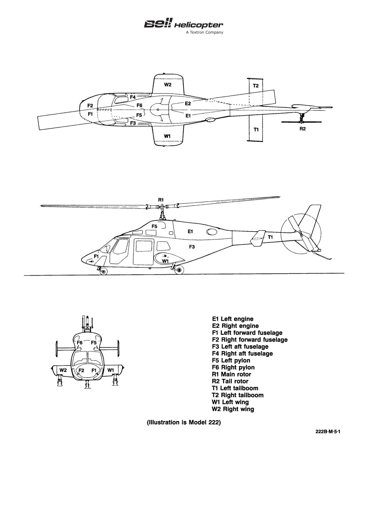
BHT-222/222B-MM-1
Figure 5-1. Maintenance Zones
5-00-00
Page 6
Rev. 7
9 SEP 2011
ECCN EAR99
BHT-222/222B-MM-1
5-6.
INSPECTION AND OVERHAUL
Scheduled inspections, special inspections, interim
TOLERANCE
inspections, or overhaul intervals required beyond the
stated tolerances must be approved by Product
Support Engineering.
WARNING
NOTE
The following is only applicable for those
DO NOT APPLY THESE TOLERANCES
operators whose governing aviation
TO PARTS WITH A LIMITED
authority requires to specifically approve
AIRWORTHINESS LIFE (CHAPTER 4).
the inspection and overhaul tolerance.
The Bell Helicopter Textron approved tolerance for
If approval of the inspection and overhaul tolerance is
scheduled inspections, special inspections, interim
required by the applicable governing aviation authority,
inspections, and overhaul intervals, unless otherwise
this is the responsibility of the owner/operator.
stated, is 10% or up to a maximum of 100 hours
operating time/30 days calendar time, whichever is
Refer to the Honeywell
101-650C/750C Series
less. The tolerances are established for maintenance
Operation and Maintenance Manual (LTS 101-2.2) for
scheduling convenience only.
inspection and overhaul tolerances.
5-00-00
9 SEP 2011 Rev. 7
Page 7/8
ECCN EAR99
BHT-222/222B-MM-1
SCHEDULED INSPECTIONS
5-7.
SCHEDULED INSPECTIONS
Table 5-1. Progressive Inspection Events
Scheduled inspections include airframe and
AIRFRAME HOURS
EVENT NUMBER
component inspections. The scheduled airframe
inspection intervals are based on the airframe
50
1
operating time. The scheduled component inspection
intervals are based on the component operating time.
100
2
150
3
5-8.
SCHEDULED AIRFRAME INSPECTIONS
200
4
Bell Helicopter Textron developed two scheduled
250
5
airframe inspection programs to give flexibility for
maximum helicopter use. An operator can choose one
300
6
of the Bell programs or design their own program. The
350
7
selection of an alternative inspection program and its
approval by the governing civil aviation authority is the
400
8
responsibility of the owner/operator.
450
9
5-9.
Airframe Periodic
500
10
550
11
Do the inspections at intervals of 50 hours, 150 hours,
and 600 hours. A minimum of one complete 50-hour,
600
12
150-hour, and
600-hour inspection must be
accomplished within 12 months.
5-12.
SCHEDULED COMPONENT INSPECTION
5-10.
Airframe Progressive
Scheduled component inspections have been
established for those items to be inspected at intervals
other than those established for helicopter periodic
The requirements of the airframe periodic 50-hour,
inspections. Do the scheduled component inspections
150-hour, and 600-hour inspections are combined in
at the intervals that follow:
12 separate events of similar workload, and are done
at
50-hour intervals. The events must be
• Every 100 hours
accomplished in the sequence shown in Table 5-1.
After Event 12 is completed, the progressive cycle
• Every 150 hours
begins again with Event
1. A minimum of one
complete cycle (12 events) must be accomplished
• Every 300 hours or 6 months
within 12 months.
• After first
300 hours and each
50 hours
5-11.
Inspection Program Selection
thereafter
You must establish the airframe periodic or the
• Every 300 hours
airframe progressive program to maintain the
helicopter from new. To change between the periodic
• (Model 222) 300 and 900 hours after initial
and progressive programs, you must first do the
installation (springless driveshaft only)
50-hour, 150-hour, and 600-hour inspections. The
owner/operator is responsible to not exceed the time
• Every 600 hours or 6 months
interval of any scheduled airframe inspection
procedure.
• Every 600 hours or 12 months
5-00-00
ECCN EAR99
9 SEP 2011 Rev. 7
Page 9
BHT-222/222B-MM-1
• Every 600 hours
• Every 1200 hours
• Every 2500 hours
• Every 6 months
• Every 2 years
• Every 3 years
• Every 5 years
• Every 10 years
5-00-00
Page 10
Rev. 7
9 SEP 2011
ECCN EAR99
BHT-222/222B-MM-1
SCHEDULED INSPECTIONS
5-12A.
3-HOURS INSPECTION
INITIAL
DATA REFERENCE
INSPECTION TASK DESCRIPTION
MECH
OTHER
DATE:
__________________
W.O.
_____________________
FACILITY:
_________________________________________
HELICOPTER S/N:
__________________________________
REGISTRY NO.:
____________________________________
TOTAL TIME:_______________________________________
SIGNATURE:_______________________________________
To be performed every 3 hours of operating time.
Chapter 65
INSPECTION OF TAIL ROTOR BLADES
ASB 222-04-100
NOTE
If tail rotor blades are annotated with “R”, no need of
following 3 flight hours repetitive inspection.
1.
Clean both surfaces of each blade around the blade
feathering bearings using aliphatic naphtha (C-305) or
detergent (C-318) or equivalent.
2.
Using a 10X power magnifying glass, closely examine the
cleaned surface, on both sides of the blade, paying particular
attention to the area around both bearings.
3.
If a crack or damage is detected, remove the tail rotor
blade from helicopter and contact Product Support Engineering
for repair procedure.
5-00-00
10 FEB 2020 Rev. 8
Page 10A/10B
Export Classification C, ECCN EAR99
BHT-222/222B-MM-1
SCHEDULED INSPECTIONS
5-13.
50-HOUR INSPECTION
INITIAL
DATA REFERENCE
INSPECTION TASK DESCRIPTION
MECH
OTHER
DATE:
__________________
W.O.
____________________
FACILITY:
________________________________________
HELICOPTER S/N:
_________________________________
REGISTRY NO.:
___________________________________
TOTAL TIME:______________________________________
SIGNATURE:______________________________________
To be performed every 50 hours of operating time or a
minimum of once every 12 months, whichever comes first.
GENERAL
1.
Log book - Review for recorded discrepancies. Correct
discrepancies on installed equipment.
2.
Make sure all applicable and required special instructions,
Alert Service Bulletins (ASB), and Airworthiness Directives
(AD) are accomplished.
Chapter 99
3.
Comply with Scheduled Inspections, Special Inspections,
Applicable Service
and required tests for all installed kits (refer to appropriate kit).
Instruction
Chapter 4
4.
Replace all limited life components that have completed
published operating limits.
Paragraph 5-59
5.
Overhaul all components that have completed published
overhaul periods.
6.
Check all exposed electrical wiring for worn or frayed
cables, loose or broken clamps, and fasteners.
5-00-00
ECCN EAR99
9 SEP 2011 Rev. 7
Page 11
BHT-222/222B-MM-1
SCHEDULED INSPECTIONS
5-13.
50-HOUR INSPECTION (CONT)
INITIAL
DATA REFERENCE
INSPECTION TASK DESCRIPTION
MECH
OTHER
Honeywell
7.
Perform applicable engine inspection.
101-650C/750C Series
Operation and
Maintenance Manual,
LTS 101-2.2
Chapter 12
8.
Lubricate helicopter components.
DETAIL
Chapter 28
1.
lnspect airframe exterior surfaces for cracks and damage.
Chapter 53
lnspect underside of fuselage and wing for evidence of fuel
leaks.
2.
Inspect nose wheel stiffener 222-031-110-081 for cracks.
Clean stiffener thoroughly prior to inspection. Pay particular
attention to horizontal leg. If crack is found in any part of
stiffener, TB 222-83-57 shall be accomplished.
Chapter 32
3.
Inspect nose landing gear doors for visible damage or
deformation. Inspect tubes and linkages for security of
attachment to door fitting and inspect for cracks in skin at door
hinges.
Chapter 32
4.
Inspect nose landing gear for condition, extend-retract and
BHT-222-CR&O-V.1
downlock actuators for leakage, and tire for proper inflation and
serviceability. Inspect wheel for cracks and serviceability.
Chapter 32
5.
Inspect main landing gear for condition, brake assemblies
BHT-222-CR&O-V.1
for hydraulic leaks and excessive lining wear, brake disc and
torque keys for condition, and tire for proper inflation and
serviceability. Inspect wheel for cracks and serviceability.
Chapter 12
6.
lnspect battery for cracks and signs of electrolyte leakage
BHT-222-CR&O-V.2
and corrosion. F1/F2
Chapter 29
7.
lnspect cyclic and collective control actuators for evidence
BHT-222-CR&O-4
of bearing wear and security of attachment at transmission
mount. lnspect piston rods for scoring, pitting, or wear, and
excessive hydraulic leakage. R1
Chapter 65
8.
lnspect main rotor pitch link universal bearings for axial
and radial wear and wear between inner races and housing. R1
5-00-00
Page 12
Rev. 7
9 SEP 2011
ECCN EAR99
BHT-222/222B-MM-1
SCHEDULED INSPECTIONS
5-13.
50-HOUR INSPECTION (CONT)
INITIAL
DATA REFERENCE
INSPECTION TASK DESCRIPTION
MECH
OTHER
NOTE
Retorque is not required if flapping springs
222-310-117-105 are installed.
BHT-222-CR&O-2
9.
Verify torque of main rotor trunnion bolts in the tightening
direction, minimum
45 foot-pounds
(61 Nm). Provided
45 foot-pounds (61 Nm) is reached without movement of bolts,
torque bolts to 53 foot-pounds (72 Nm). If any bolt moves
before 45 foot-pounds (61 Nm) is reached, remove all six bolts
and visually inspect for cracks or signs of yielding. If any
defective bolts are found, replace all six bolts. If no defect(s)
are found, reinstall bolts. R1
Chapter 65
10. For all main rotor hub assemblies, verify torque of main
BHT-222-CR&O-2
rotor
flapping bearing(s) retaining bolt/nuts. Apply
100 foot-pounds (135 Nm) of torque to the nut, in the tightening
direction. Provided 100 foot-pounds (135 Nm) of torque is
reached without movement of the nut, torque the bolt/nut to
125 foot-pounds
(169 Nm). If any nut moves before
100 foot-pounds
(135 Nm) of torque is reached, remove
flapping bearing from main rotor hub assembly. Inspect/repair
flapping bearing and main rotor yoke assemblies. R1
Chapter 65
11. (Model 222) Inspect main rotor blade 222-015-500-101/
-105 upper and lower center spar doublers for debonding.
Chapter 71
12. If installed, inspect external engine oil filters for impending
bypass. E1/E2
Chapter 29
13. lnspect tail rotor control actuator for evidence of bearing
wear, security of attachment, and evidence of leakage. F3/F4
Chapter 65
14. lnspect tail rotor pitch links for worn bearings and freedom
BHT-ALL-SPM
of operation. R2
15. Remove all chip detectors from engine oil systems; i.e.,
flow, accessory gearbox, and the No. 2 and No. 3 bearing
scavenge line. F5/F6, E1/E2
Honeywell Service
a. Inspect each chip detector for metal contamination.
Bulletin
LT 101-77-30-0104
5-00-00
ECCN EAR99
9 SEP 2011 Rev. 7
Page 13
BHT-222/222B-MM-1
SCHEDULED INSPECTIONS
5-13.
50-HOUR INSPECTION (CONT)
INITIAL
DATA REFERENCE
INSPECTION TASK DESCRIPTION
MECH
OTHER
b. With electrical power ON, use a small length of wire
and bridge gap at a tip of each detector. Verify corresponding
engine chip light segment on caution panel illuminates. If
caution lights fail to illuminate, correct fault prior to operation of
helicopter.
c. Reinstall all chip detectors in both engines.
d. Press ENGINE CHIP TEST SWITCH. Make sure all
engine chip light segments illuminate.
NOTE
Clean more frequently if operating in a corrosive
environment or if deemed necessary due to extreme
environmental conditions.
Chapter 65
16. Clean main and tail rotor blades. R1/R2
CAUTION
ON BLADES THAT HAVE EROSION PROTECTION
TAPE INSTALLED, CARE MUST BE TAKEN TO
PREVENT PRESERVATIVE OIL FROM
CONTACTING THE TAPE. CORROSION
PREVENTIVE COMPOUND (C-125) WILL
DETERIORATE THE TAPE ADHESION.
NOTE
It is not necessary to apply preservative oil to the
blade fiberglass skin. One inch of the fiberglass skin
adjacent to the metal components may be coated
with corrosion preventive compound (C-125) to
ensure complete protection.
17. When dry, apply corrosion preventive compound (C-125)
to grip plates, doublers, abrasive strips, spar doublers, and
trailing edge doublers on upper and lower surfaces of blades.
R1/R2
5-00-00
Page 14
Rev. 7
9 SEP 2011
ECCN EAR99
BHT-222/222B-MM-1
SCHEDULED INSPECTIONS
5-13.
50-HOUR INSPECTION (CONT)
INITIAL
DATA REFERENCE
INSPECTION TASK DESCRIPTION
MECH
OTHER
Chapter 65
18. Inspection of tail rotor blades:
ASB 222-04-100
NOTE
If tail rotor blades are annotated with “R”, no need of
following 50 hour repetitive inspection.
a. Clean both surfaces of each blade around the blade
feathering bearings using aliphatic naphtha (C-305) or
detergent (C-318) or equivalent.
b. Using a 10X power magnifying glass, closely examine
the cleaned surface, on both sides of the blade, paying
particular attention to the area around both bearings.
c. If a crack or damage is detected, remove the tail rotor
blade from helicopter and contact Product Support Engineering
for repair procedure.
5-00-00
10 FEB 2020 Rev. 8
Page 14A/14B
Export Classification C, ECCN EAR99
BHT-222/222B-MM-1
SCHEDULED INSPECTIONS
5-14.
150-HOUR INSPECTION
INITIAL
DATA REFERENCE
INSPECTION TASK DESCRIPTION
MECH OTHER
DATE:
__________________
W.O.
____________________
FACILITY:
________________________________________
HELICOPTER S/N:
_________________________________
REGISTRY NO.:
___________________________________
TOTAL TIME:______________________________________
SIGNATURE:______________________________________
To be performed every 150 hours of operating time or a
minimum of once every 12 months, whichever comes first.
GENERAL
1.
Log book - Review for recorded discrepancies. Correct
discrepancies on installed equipment.
2.
Make sure all applicable and required special inspections,
Alert Service Bulletins (ASB), and Airworthiness Directives
(AD) are accomplished.
Chapter 99
3.
Comply with Scheduled Inspections, Special Inspections,
Applicable Service
and required tests for all installed kits (refer to appropriate kit).
Instructions
Chapter 4
4.
Replace all limited life components that have completed
published operating limits.
Paragraph 5-59
5.
Overhaul all components that have completed published
overhaul periods.
6.
Check all exposed electrical wiring for worn or frayed
cables, loose or broken clamps, and fasteners.
5-00-00
ECCN EAR99
9 SEP 2011 Rev. 7
Page 15
BHT-222/222B-MM-1
SCHEDULED INSPECTIONS
5-14.
150-HOUR INSPECTION (CONT)
INITIAL
DATA REFERENCE
INSPECTION TASK DESCRIPTION
MECH OTHER
Honeywell
7.
Perform applicable engine inspection.
101-650C/750C Series
Operation and
Maintenance Manual,
LTS 101-2.2
Chapter 12
8.
Lubricate helicopter components.
DETAIL
Chapter 25
1.
lnspect seat cushions and seat backs for tears, excessive
deterioration, and security of attachment. F1/F2, F3/F4
Chapter 25
2.
lnspect seat assemblies for security of attachment. F1/F2,
F3/F4
Chapter 25
3.
lnspect safety belts and shoulder harnesses for
deterioration and security of attachment. F1/F2, F3/F4
Chapter 52
4.
lnspect crew doors, passenger doors, and baggage
compartment doors for corrosion damage, distortion, positive
locking mechanisms, seals for tears or separations, and doors
for security of attachment. F1/F2, F3/F4
Chapter 26
5.
lnspect cabin fire extinguisher for security and condition,
damage, corrosion, and quick opening clamp for operation and
security. F1/F2
Chapter 11
6.
lnspect placards and instrument panel decals, and all
Chapter 95
instrument markings for appearance and legibility. F1/F2
Applicable Flight
Manual
Chapter 96
7.
Remove battery. lnspect vent lines for obstructions or
damage, and clean battery mounting area prior to installing a
serviceable battery. F1/F2
Chapter 52
8.
lnspect nose compartment electrical components for
Chapter 96
condition and security of mounting, all electrical harnesses and
cables for frayed wires, loose or broken clamps, and fasteners.
lnspect nose door for obvious damage and security of latching.
F1/F2
Chapter 95
9.
lnspect pitot tube(s) for security of attachment. F1/F2
5-00-00
Page 16
Rev. 7
9 SEP 2011
ECCN EAR99
BHT-222/222B-MM-1
SCHEDULED INSPECTIONS
5-14.
150-HOUR INSPECTION (CONT)
INITIAL
DATA REFERENCE
INSPECTION TASK DESCRIPTION
MECH OTHER
Chapter 27
10. lnspect roof mounted cyclic and collective shaft
BHT-ALL-SPM
assemblies and control tubes for bearing binding, corrosion or
mechanical damage, wear, and security of attachment. F5/F6
NOTE
Examine inspection window(s) and/or glass(es) for
cracking and discoloration. If either of these
conditions are present, the part must be removed
and replaced prior to returning helicopter for service.
Chapter 29
11. lnspect hydraulic lines for leaks, system PC-1 and PC-2
reservoirs for proper level and discoloration of fluid, and
module for differential pressure indication. Check for chafe
guard deterioration, and verify flexible hoses are in satisfactory
condition and exhibit no indications of chafing. F5/F6
Chapter 66
12. Visually inspect the outboard and inboard collective lever
idler link attachment points for condition in area of lugs in
transmission top case. R1
BHT-222-CR&O-2
13. Inspect hydraulic actuator support attaching nuts for
proper torque. R1
Chapter 65
14. lnspect cyclic and collective control levers, swashplate
assembly, drive assembly, and links for evidence of damage,
security, and corrosion. lnspect walking beam pitch change
bearings, ensuring that seals and shields are in place and pitch
link clevis is properly aligned with walking beam. If seals and/or
shields are missing or loose, bearing must be replaced. R1
BHT-222-CR&O-2
15. lnspect main rotor hub for damage and security, static
stops for damage from hard mast contact, and trunnion shims
for condition. lnspect yoke for condition in area around flapping
bearing attachment bushings. lnspect pendulum dampers for
freedom of movement. R1
5-00-00
ECCN EAR99
9 SEP 2011 Rev. 7
Page 17
BHT-222/222B-MM-1
SCHEDULED INSPECTIONS
5-14.
150-HOUR INSPECTION (CONT)
INITIAL
DATA REFERENCE
INSPECTION TASK DESCRIPTION
MECH OTHER
Chapter 65
16. For all main rotor hub assemblies, verify torque of main
BHT-222-CR&O-2
rotor grip(s) retaining bolts/nuts. Apply
100 foot-pounds
(135 Nm) of torque to the nut, in the tightening direction.
Provided 100 foot-pounds (135 Nm) of torque is reached
without movement of the nut, torque the bolt/nut to
125 foot-pounds
(169 Nm). If any nut moves before
100 foot-pounds (135 Nm) of torque is reached, remove grip
from main rotor hub assembly. Inspect/repair pitch horn and
grip assemblies. R1
BHT-222-CR&O-2
17. Visually inspect the accessible portion of the main rotor
elastomeric pitch axis bearings, trunnion bearings, and flapping
springs for evidence of delamination or loss of elastomer.
Chapter 65
18. lnspect main rotor blades for obvious damage and for
cleanliness. R1
NOTE
Examine inspection window(s) and/or glass(es) for
cracking and discoloration. If either of these
conditions are present, the part must be removed
and replaced prior to returning helicopter for service.
Chapter 66
19. lnspect transmission for evidence of oil leakage and
correct fluid level. F5/F6
Chapter 66
20. Remove transmission chip detectors. lnspect and clean
detectors and test electrical circuits. Install chip detectors. R1
Chapter 66
21. lnspect main driveshafts overtemperature indicators
BHT-222-CR&O-3
(TEMP-PLATES) on transmission-end and engine-end
driveshaft couplings for evidence of overheating (discoloration)
and grease leakage. R1
Chapter 66
22. lnspect tail rotor driveshaft coupling overtemperature
BHT-222-CR&O-3
indicators (TEMP-PLATES) for evidence of overheating
(discoloration) and grease leakage. R1
Chapter 66
23. lnspect rotor brake assembly for evidence of hydraulic
leakage, security of attachment, and excessive wear of brake
linings. Check brake disc for damage. Check reservoir for fluid
level and discoloration. R1/F6
5-00-00
Page 18
Rev. 7
9 SEP 2011
ECCN EAR99
BHT-222/222B-MM-1
SCHEDULED INSPECTIONS
5-14.
150-HOUR INSPECTION (CONT)
INITIAL
DATA REFERENCE
INSPECTION TASK DESCRIPTION
MECH OTHER
NOTE
Examine inspection window(s) and/or glass(es) for
cracking and discoloration. If either of these
conditions are present, the part must be removed
and replaced prior to returning helicopter for service.
Chapter 12
24. lnspect right and left engine oil tanks and lines for
Chapter 79
evidence of leakage. Check for proper quantity of oil. F5/F6
Chapter 66
25. lnspect right and left nodal beam assembly as follows:
a. Flexure assembly for cracks in fiberglass, shear pad
debond/delamination, and security. F5/F6
b. Cam bearing for evidence of grease loss, overheating,
and grease seal condition. F5/F6
c. Weight and cam arms for indications of misalignment
and chafing. F5/F6
d. Restraint arms and lift links for security, damage, and
elastomeric bearings for obvious damage. F5/F6
e. Visually inspect the outside surfaces of station 270
bulkhead at and around the area of attachment fittings
222-031-592-103 to the bulkhead for cracks and damage.
Chapter 66
26. lnspect the left longitudinal isolation mount and support for
damage and security. F5
Chapter 66
27. lnspect the right longitudinal isolation mount and support,
and the lateral isolation mount and support for damage and
security. F6
5-00-00
Export Classification C, ECCN EAR99
10 FEB 2020 Rev. 8
Page 19
BHT-222/222B-MM-1
SCHEDULED INSPECTIONS
5-14.
150-HOUR INSPECTION (CONT)
INITIAL
DATA REFERENCE
INSPECTION TASK DESCRIPTION
MECH OTHER
CAUTION
INGESTION OF BROKEN INLET SCREEN
SEGMENTS CAN CAUSE FOREIGN OBJECT
DAMAGE TO ENGINE COMPRESSOR SECTION.
Chapter 71
28. lnspect both engine inlet screens for damage. F5/F6
Chapter 71
29. lnspect all firewalls and fireshields for cracks, distortion,
loose or missing rivets, broken spot welds, deteriorating seals,
and sealant. E1/E2
Chapter 71
30. lnspect left power plant area for evidence of fuel and oil
leaks, flexible and rigid fuel and oil lines for wear, chafing,
damage, and security of attachment. E1
Chapter 71
31. lnspect left engine mounts and accessories for damage
and security of attachment. E1
Chapter 76
32. Inspect left engine throttle control housing, push rod, and
lever for wear or lost motion and for security of attachment. E1
33. Inspect left engine ejector for security of attachment at
plenum and support link. E1
Chapter 71
34. Remove left engine air inlet duct assembly. Inspect duct
assembly for delamination. Inspect reverse flow baffle door for
security of attachment and general condition. E1
Chapter 66
35. Remove the left aft fairing assembly and inspect the
forward tail rotor driveshaft hanger assembly for security of
attachment, cracks at mounting ears, and corrosion or
mechanical damage. Check bearing for evidence of grease
seal leakage and discoloration caused by overheating. E1
Chapter 66
36. Inspect forward tail rotor driveshaft hanger coupling disc
assembly for cracks radiating from bolt holes, corrosion,
wrinkles, or other evidence of overstress. E1
5-00-00
Page 20
Rev. 7
9 SEP 2011
ECCN EAR99
BHT-222/222B-MM-1
SCHEDULED INSPECTIONS
5-14.
150-HOUR INSPECTION (CONT)
INITIAL
DATA REFERENCE
INSPECTION TASK DESCRIPTION
MECH OTHER
Chapter 27
37. Remove access panel from bottom of aft fuselage and
Chapter 29
inspect bellcrank and directional control hydraulic actuator
supports for corrosion and mechanical damage. lnspect
actuator for hydraulic leakage, bearing wear, and security of
attachment. F3/F4
NOTE
Examine inspection window(s) and/or glass(es) for
cracking and discoloration. If either of these
conditions are present, the part must be removed
and replaced prior to returning helicopter for service.
Chapter 26
38. lnspect right and left engine fire bottles for proper pressure
indication. F3/F4
Chapter 66
39. Remove forward and aft tail rotor driveshaft covers and
inspect hanger assemblies for security of attachment, cracks at
mounting ears, and corrosion or mechanical damage. Check
bearings for evidence of grease seal leakage and discoloration
caused by overheating. T1/T2
Chapter 66
40. lnspect driveshaft hanger coupling discs and the disc at
the tail rotor gearbox input quill for cracks radiating from bolt
holes, corrosion, wrinkles, or other evidence of overstress. T1/T2
41. Visually inspect horizontal stabilizer auxiliary fins for
Chapter 53
obvious damage and security of attachment. T1/T2
42. Visually inspect upper and lower surface of stabilizer for
Chapter 53
crack(s) indications immediately adjacent to stabilizer support
attaching stabilizer to tailboom. T1/T2
43. lnspect tail skid for obvious damage and security of
Chapter 53
attachment. T1/T2
44. lnspect vertical fin assembly for damage. T1/T2
Chapter 53
5-00-00
ECCN EAR99
9 SEP 2011 Rev. 7
Page 21
BHT-222/222B-MM-1
SCHEDULED INSPECTIONS
5-14.
150-HOUR INSPECTION (CONT)
INITIAL
DATA REFERENCE
INSPECTION TASK DESCRIPTION
MECH OTHER
CAUTION
HARDWARE AND TORQUE REQUIREMENTS OF
THE VERTICAL FIN INSTALLATION ARE
AFFECTED BY ACCOMPLISHMENT OF
TB 222-98-156.
45. lnspect the vertical fin attachment bolts/nuts for proper
torque as follows:
a. For helicopters prior to TB 222-98-156, torque the nut
in the tightening direction while restraining the bolt head. If
90 inch-pounds (10 Nm) of torque is reached without nut
movement, increase the torque to 110 inch-pounds (12.5 Nm)
of torque. If the nut moves below 90 inch-pounds (10 Nm) of
torque, proceed with 2-year Inspection.
b. For helicopters after TB 222-98-156, torque the nut in
the tightening direction while restraining the bolt head. If
130 inch-pounds (14.5 Nm) of torque is reached without nut
movement, increase torque to 160 inch-pounds (18 Nm) of
torque. If the nut moves below 130 inch-pounds (14.5 Nm),
proceed with 2-year Inspection.
NOTE
Examine inspection window(s) and/or glass(es) for
cracking and discoloration. If either of these
conditions are present, the part must be removed
and replaced prior to returning helicopter for service.
Chapter 12
46. Remove tail rotor gearbox fairing and inspect tail rotor
Chapter 66
gearbox for oil leakage, mechanical or corrosion damage, and
security of mounting. Check for proper oil level. T1/T2
Chapter 66
47. Remove tail rotor gearbox chip detector, clean and inspect
detector, and test electrical circuit. Install chip detector. R2
48. Inspect tail rotor gearbox retaining nuts for proper torque.
5-00-00
Page 22
Rev. 7
9 SEP 2011
ECCN EAR99
BHT-222/222B-MM-1
SCHEDULED INSPECTIONS
5-14.
150-HOUR INSPECTION (CONT)
INITIAL
DATA REFERENCE
INSPECTION TASK DESCRIPTION
MECH OTHER
49. Inspect tail rotor pitch control assembly as follows:
a. Check for excessive radial play between the pitch
control assembly and the tail rotor gearbox output shaft due to
a worn or debonded guide bearing. Radial play in excess of
0.018 inch (0.5080 mm) is considered excessive.
b. Check for worn areas on the tail rotor gearbox output
shaft wear sleeve.
c. Check for worn or rough crosshead bearing set.
d. Check for rough or worn counterweight bellcrank
bearings.
e. Check for worn inner race in the tail rotor idler
assembly.
f. Check for unbonded bearing in the upper leg of tail
rotor input lever assembly.
g. Check for worn bearings in the tail rotor pitch links.
Chapter 65
50. Inspect tail rotor hub and blades for cleanliness, visible
damage to blades, evidence of wear or excessive play in pitch
change bearings and trunnion bearings, and pitch horn for
security. R2
Chapter 65
51. Inspect tail rotor hub and blades assembly retaining nut for
proper torque. R2
NOTE
This inspection is applicable to tail rotor hub and
blades
assembly
prior
to
upgrade
per
TB 222-06-174 (Part II).
52. Inspect tail rotor blades pitch change bearings as follows:
a. Without removing the blade, clean exposed areas of
pitch change bearings.
5-00-00
ECCN EAR99
9 SEP 2011 Rev. 7
Page 23
BHT-222/222B-MM-1
SCHEDULED INSPECTIONS
5-14.
150-HOUR INSPECTION (CONT)
INITIAL
DATA REFERENCE
INSPECTION TASK DESCRIPTION
MECH OTHER
BHT-222-CR&O-3
b. With the blade bolts torqued to the highest value of
torque range, visually inspect each bearing inner member neck
area (full 360°) for cracks. If cracks are found, replace both
bearings in blade.
BHT-222-CR&O-3
c. Visually inspect chamfered washers installed in direct
contact with the outboard surface of the yoke for deformation.
Deformed washers must be replaced.
Chapter 71
53. Inspect right power plant area for evidence of fuel and oil
leaks, flexible and rigid fuel and oil lines for wear, chafing,
damage, and security of attachment. E2
Chapter 71
54. Inspect right engine mounts and accessories for damage
and security of attachment. E2
Chapter 76
55. Inspect right engine throttle control push rod, lever, and
bellcrank for lost motion and security of attachment. E2
56. Inspect right engine ejector for security of attachment at
plenum and support link. E2
Chapter 71
57. Remove right engine air inlet duct assembly. Inspect duct
assembly for delamination. Inspect reverse flow baffle door for
security of attachment and general condition. E2
5-00-00
Page 24
Rev. 7
9 SEP 2011
ECCN EAR99
BHT-222/222B-MM-1
SCHEDULED INSPECTIONS
5-15.
600-HOUR INSPECTION
INITIAL
DATA REFERENCE
INSPECTION TASK DESCRIPTION
MECH
OTHER
DATE:
__________________
W.O.
_____________________
FACILITY:
_________________________________________
HELICOPTER S/N:
__________________________________
REGISTRY NO.:
____________________________________
TOTAL TIME:_______________________________________
SIGNATURE:_______________________________________
To be performed every 600 hours of operating time or a
minimum of once every 12 months, whichever comes first.
DETAIL
Chapter 7
1.
Inspect landing gear as follows:
Chapter 29
Chapter 32
a. Jack helicopter clear of ground and cycle landing gear.
Check for binding, excessive cycle time, proper light operation,
and proximity switch operation and adjustment. Check nose
gear centering actuator for correct pressure.
b. Perform emergency drop check.
c. Remove oleo inflation valve and check for indication of
hydraulic fluid.
2.
lnspect first aid kit contents. Replace any items that are
damaged or time expired. Replace any items with deteriorated
packaging. F2
Chapter 12
3.
Remove left, center, and right bottom access panels
Chapter 27
beneath the crew compartment. lnspect all installed control
tubes, links, rod end bearings, bellcranks, supports, and
attachment bolts for corrosion, evidence of wear, and security of
attachment. lnspect spring cartridges and rotary actuators for
security. F1/F2
5-00-00
ECCN EAR99
9 SEP 2011 Rev. 7
Page 25
BHT-222/222B-MM-1
SCHEDULED INSPECTIONS
5-15.
600-HOUR INSPECTION (CONT)
INITIAL
DATA REFERENCE
INSPECTION TASK DESCRIPTION
MECH
OTHER
Chapter 27
4.
Check cyclic stick, collective stick, and tail rotor pedal
minimum friction. Adjust if necessary. F2
Chapter 12
5.
Remove access panels along bottom centerline of fuselage
to FS 356.00. F3/F4
Chapter 27
a. lnspect directional control tubes, rod end bearings,
bellcranks, supports, and attachment bolts for corrosion,
evidence of wear, and security of attachments. F3/F4
b. Check wiring bundles for security and evidence of
chafing. Visually inspect all exposed structure for corrosion,
distortion, or cracks. F3/F4
Chapter 29
c. lnspect directional control actuator for leaks and
security of attachment, and FS 340.00 bulkhead structure for
distortion or cracks. F3/F4
Chapter 27
6.
Open control tunnel access in the canted bulkhead behind
BHT-ALL-SPM
the pilot station. lnspect the lower and upper cyclic and
collective pitch control bellcranks for bearing security of
attachment, corrosion or mechanical damage to clevises, and
security of attachment to supports and control tube bearings.
F5/F6
Chapter 25
7.
On helicopters equipped with emergency exit windows in
the passenger doors and/or aft window position, inspect as
follows after removing interior trim from around windows: F3/F4
a. On passenger door only, visually inspect window
retainer to door frame bond. Replace the retainer if it is not
securely bonded to the frame at all points except at the two
lower corners. F3/F4
b. Visually inspect the inboard side of all rubber retainers.
Any nicks or cracks in the retainer is cause for replacement of
the retainer. F3/F4
c. Check that all filler strips and pull tab are firmly seated
in their retainer grooves. F3/F4
Chapter 25
d. Install interior trim. F3/F4
5-00-00
Page 26
Rev. 7
9 SEP 2011
ECCN EAR99
BHT-222/222B-MM-1
SCHEDULED INSPECTIONS
5-15.
600-HOUR INSPECTION (CONT)
INITIAL
DATA REFERENCE
INSPECTION TASK DESCRIPTION
MECH
OTHER
Chapter 53
8.
lnspect horizontal stabilizer center area as follows: T1/T2
a. Remove upper support assembly. Save attaching
hardware.
b. Clean upper surface of stabilizer.
NOTE
Surface must be free of all dirt and residue.
c. With bright light, inspect upper surface for any cracks,
corrosion, or working rivets.
d. If no cracks, corrosion, or working rivets are located,
install support assembly.
e. Remove lower support assembly. Save attaching
hardware.
f. Clean lower surface of stabilizer.
g. With bright light, inspect lower surface for any cracks,
corrosion, or working rivets.
h. If no cracks, corrosion, or working rivets are located,
install support assembly.
Chapter 27
9.
Remove aft right fuselage access panel and inspect control
tube, bellcrank, and support assembly for security of
attachment, corrosion or mechanical damage, and excessively
worn bearings and clevises. F4
Chapter 27
10. Remove and inspect tail rotor control tube, nylatron
BHT-222-CR&O-4
sleeves, and heat shrink (if installed) at four areas where tube
contacts tailboom fairleads. T1/T2
Chapter 66
11. lnspect tail rotor driveshaft hanger bearings for roughness
by disconnecting shaft from transmission and tail rotor gearbox.
Rotate by hand while feeling hangers. Verify torque of tail rotor
hanger splined adapter nut. T1/T2
Chapter 65
12. lnspect tail rotor blade attaching bolts/nuts for proper
torque. R2
5-00-00
ECCN EAR99
9 SEP 2011 Rev. 7
Page 27
BHT-222/222B-MM-1
SCHEDULED INSPECTIONS
5-15.
600-HOUR INSPECTION (CONT)
INITIAL
DATA REFERENCE
INSPECTION TASK DESCRIPTION
MECH
OTHER
13. lnspect tail rotor blades pitch change bearings as follows:
Chapter 65
a. Without removing the blade, clean exposed areas of
pitch change bearings.
BHT-222-CR&O-3
b. With the blade bolts torqued to the highest value of
torque range, visually inspect each bearing inner member neck
area (full 360°) for cracks. If cracks are found, replace both
bearings in blade.
BHT-222-CR&O-3
c. Visually inspect chamfered washers installed in direct
contact with the outboard surface of the yoke for deformation.
Deformed washers must be replaced.
14. Inspect station 270 bulkhead for crack and damage as
follows:
a. Remove equipment installed and interior trim to gain
access to the underside of station 270 bulkhead.
b. Remove transmission drain pan from aft cabin.
c. Remove screws retaining the door 222-031-506-043 to
the bottom side of the station 270 bulkhead. Remove the access
door.
d. Using a bright light, inspect the outside and inside
surfaces of the bulkhead assembly for cracks and damage,
paying particular attention to the area around the rivets/
Hi-Locks attaching the aft nodal beam fittings 222-031-592-103
to the station 270 bulkhead.
e. If a crack or damage is detected, contact Product
Support Engineering for repair procedure.
15. Remove the fairing cover plates and examine the wing(s)
to fuselage attachment points for corrosion, looseness, and
damage. Check torque of attaching bolts/nuts.
16. Remove baggage compartment floor and examine the
following:
a. Examine surrounding aft fuselage structure for
corrosion and damage.
5-00-00
Page 28
Rev. 8
10 FEB 2020
Export Classification C, ECCN EAR99
BHT-222/222B-MM-1
SCHEDULED INSPECTIONS
5-15.
600-HOUR INSPECTION (CONT)
INITIAL
DATA REFERENCE
INSPECTION TASK DESCRIPTION
MECH
OTHER
b. Examine wiring bundles for chafing. Make sure they are
correctly attached.
c. Examine the environmental control unit for general
condition. Make sure it is correctly attached. Examine bleed air
tubing connection for leakage. Make sure all tubes and
connectors are securely attached.
d. If installed, examine auxiliary fuel system components,
wiring and tubing for corrosion, chafing, and correct attachment.
5-00-00
9 SEP 2011 Rev. 7
Page 29/30
ECCN EAR99
BHT-222/222B-MM-1
SCHEDULED INSPECTIONS
5-16.
PROGRESSIVE INSPECTION - EVENT 1
INITIAL
DATA REFERENCE
INSPECTION TASK DESCRIPTION
MECH
OTHER
DATE:
__________________
W.O.
_____________________
FACILITY:
_________________________________________
HELICOPTER S/N:
__________________________________
REGISTRY NO.:
____________________________________
TOTAL TIME:_______________________________________
SIGNATURE:_______________________________________
GENERAL
Paragraph 5-13
1.
Perform a complete 50-hour inspection.
DETAIL
NOTE
Examine inspection window(s) and/or glass(es) for
cracking and discoloration. If either of these
conditions are present, the part must be removed
and replaced prior to returning helicopter for service.
Chapter 26
1.
Inspect right and left engine fire bottles for proper pressure
indication. F3/F4
Chapter 27
2.
Remove access panel from bottom of aft fuselage and
Chapter 29
inspect bellcrank and directional control hydraulic
actuator supports for corrosion and mechanical damage.
Inspect actuator for hydraulic leakage, bearing wear, and
security of attachment. F3/F4
Chapter 66
3.
Remove the left aft fairing assembly and inspect the
forward tail rotor driveshaft hanger assembly for security of
attachment, cracks at mounting ears, and corrosion or
mechanical damage. Check bearing for evidence of grease seal
leakage, and discoloration caused by overheating. E1
5-00-00
ECCN EAR99
9 SEP 2011 Rev. 7
Page 31
BHT-222/222B-MM-1
SCHEDULED INSPECTIONS
5-16.
PROGRESSIVE INSPECTION - EVENT 1 (CONT)
INITIAL
DATA REFERENCE
INSPECTION TASK DESCRIPTION
MECH
OTHER
Chapter 66
4.
lnspect forward tail rotor driveshaft hanger coupling disc
assembly for cracks radiating from bolt holes, corrosion,
wrinkles, or other evidence of overstress. E1
Chapter 66
5.
Remove forward and aft tail rotor driveshaft covers and
inspect hanger assemblies for security of attachment, cracks at
mounting ears, and corrosion or mechanical damage. Check
bearings for evidence of grease seal leakage and discoloration
caused by overheating. T1/T2
Chapter 66
6.
lnspect driveshaft hanger coupling discs and the disc at the
tail rotor gearbox input quill for cracks radiating from bolt holes,
corrosion, wrinkles, or other evidence of overstress. T1/T2
Chapter 53
7.
Visually inspect horizontal stabilizer auxiliary fins for
obvious damage and security of attachment. T1/T2
Chapter 53
8.
Visually inspect upper and lower surface of stabilizer for
indications of cracks immediately adjacent to stabilizer support
attaching stabilizer to tailboom. T1/T2
Chapter 53
9.
lnspect tail skid for obvious damage and security of
attachment. T1/T2
Chapter 53
10. lnspect vertical fin assembly for damage. T1/T2
CAUTION
HARDWARE AND TORQUE REQUIREMENTS OF
THE VERTICAL FIN INSTALLATION ARE
AFFECTED BY ACCOMPLISHMENT OF
TB 222-98-156.
Chapter 53
11. lnspect the vertical fin attachment bolts/nuts for proper
torque as follows:
a. For helicopters prior to TB 222-98-156, torque the nut in
the tightening direction while restraining the bolt head. If
90 inch-pounds (10 Nm) of torque is reached without nut
movement, increase the torque to 110 inch-pounds (12.5 Nm) of
torque. If the nut moves below 90 inch-pounds (10 Nm) of
torque, proceed with 2-year Inspection.
5-00-00
Page 32
Rev. 7
9 SEP 2011
ECCN EAR99
BHT-222/222B-MM-1
SCHEDULED INSPECTIONS
5-16.
PROGRESSIVE INSPECTION - EVENT 1 (CONT)
INITIAL
DATA REFERENCE
INSPECTION TASK DESCRIPTION
MECH
OTHER
b. For helicopters after TB 222-98-156, torque the nut in
the tightening direction while restraining the bolt head. If
130 inch-pounds (14.5 Nm) of torque is reached without nut
movement, increase torque to 160 inch-pounds (18 Nm) of
torque. If the nut moves below 130 inch-pounds (14.5 Nm),
proceed with 2-year Inspection.
NOTE
Examine inspection window(s) and/or glass(es) for
cracking and discoloration. If either of these
conditions are present, the part must be removed
and replaced prior to returning helicopter for service.
Chapter 12
12. Remove tail rotor gearbox fairing and inspect tail rotor
Chapter 66
gearbox for oil leakage, mechanical or corrosion damage, and
security of mounting. Check for proper oil level. T1/T2
Chapter 66
13. Remove tail rotor gearbox chip detector. Inspect and clean
detector and test electrical circuit. Install chip detector. R2
14. Inspect tail rotor gearbox retaining nuts for proper torque.
15. Inspect tail rotor pitch control assembly as follows:
a. Check for excessive radial play between the pitch
control assembly and the tail rotor gearbox output shaft due to a
worn or debonded guide bearing. Radial play in excess of 0.018
inch (0.5080 mm) is considered excessive.
b. Check for worn areas on the tail rotor gearbox output
shaft wear sleeve.
c. Check for worn or rough crosshead bearing set.
d. Check for rough or worn counterweight bellcrank
bearings.
e. Check for worn inner race in the tail rotor idler
assembly.
f. Check for unbonded bearing in the upper leg of tail rotor
input lever assembly.
5-00-00
ECCN EAR99
9 SEP 2011 Rev. 7
Page 33
BHT-222/222B-MM-1
SCHEDULED INSPECTIONS
5-16.
PROGRESSIVE INSPECTION - EVENT 1 (CONT)
INITIAL
DATA REFERENCE
INSPECTION TASK DESCRIPTION
MECH
OTHER
g. Check for worn bearings in the tail rotor pitch links.
Chapter 65
16. Inspect tail rotor hub and blades for cleanliness, visible
damage to blades, evidence of wear or excessive play in pitch
change bearings, and trunnion bearings and pitch horn for
security. R2
Chapter 65
17. Inspect tail rotor hub and blades assembly retaining nut for
proper torque. R2
NOTE
This inspection is applicable to tail rotor hub and
blades assembly prior to upgrade per TB 222-06-174
(Part II).
18. Inspect tail rotor blades pitch change bearings as follows:
a. Without removing the blade, clean exposed areas of
pitch change bearings.
BHT-222-CR&O-3
b. With the blade bolts torqued to the highest value of
torque range, visually inspect each bearing inner member neck
area (full 360°) for cracks. If cracks are found, replace both
bearings in blade.
BHT-222-CR&O-3
c. Visually inspect chamfered washers installed in direct
contact with the outboard surface of the yoke for deformation.
Deformed washers must be replaced.
5-00-00
Page 34
Rev. 7
9 SEP 2011
ECCN EAR99
BHT-222/222B-MM-1
SCHEDULED INSPECTIONS
5-17.
PROGRESSIVE INSPECTION - EVENT 2
INITIAL
DATA REFERENCE
INSPECTION TASK DESCRIPTION
MECH
OTHER
DATE:
__________________
W.O.
_____________________
FACILITY:
_________________________________________
HELICOPTER S/N:
__________________________________
REGISTRY NO.:
____________________________________
TOTAL TIME:_______________________________________
SIGNATURE:_______________________________________
GENERAL
Paragraph 5-13
1.
Perform a complete 50-hour inspection.
DETAIL
Chapter 66
1.
Inspect right and left nodal beam assembly as follows:
a. Flexure assembly for cracks in fiberglass, shear pad
debond/delamination, and security. F5/F6
b. Cam bearing for evidence of grease loss, overheating,
and grease seal condition. F5/F6
c. Weight and cam arms for indications of misalignment
and chafing. F5/F6
d. Restraint arms and lift links for security, damage, and
elastomeric bearings for obvious damage. F5/F6
e. Visually inspect the outside surfaces of station
270
bulkhead at and around the area of attachment fittings
222-031-592-103 to the bulkhead for cracks and damage.
5-00-00
Export Classification C, ECCN EAR99
10 FEB 2020 Rev. 8
Page 35
BHT-222/222B-MM-1
SCHEDULED INSPECTIONS
5-17.
PROGRESSIVE INSPECTION - EVENT 2 (CONT)
INITIAL
DATA REFERENCE
INSPECTION TASK DESCRIPTION
MECH
OTHER
NOTE
Examine inspection window(s) and/or glass(es) for
cracking and discoloration. If either of these
conditions are present, the part must be removed
and replaced prior to returning helicopter for service.
Chapter 66
2.
lnspect transmission for evidence of oil leakage and correct
fluid level. F5/F6
Chapter 66
3.
Remove transmission chip detectors. lnspect and clean
detectors and test electrical circuits. Install chip detectors. R1
Chapter 66
4.
lnspect the left longitudinal isolation mount and support for
damage and security. F5/F6
Chapter 66
5.
lnspect the right longitudinal isolation mount and support,
and the lateral isolation mount and support for damage and
security. F6
Chapter 66
6.
lnspect rotor brake assembly for evidence of hydraulic
leakage, security of attachment, and excessive wear of brake
linings. Check brake disc for damage. Check reservoir for fluid
level and discoloration. R1/F6
Chapter 66
7.
lnspect tail rotor driveshaft coupling overtemperature
BHT-222-CR&O-3
indicators (TEMP-PLATES) for evidence of overheating
(discoloration) and grease leakage. R1
Chapter 66
8.
lnspect main driveshafts overtemperature indicators
BHT-222-CR&O-3
(TEMP-PLATES) on transmission-end and engine-end
driveshaft couplings for evidence of overheating (discoloration)
and grease leakage. R1
NOTE
Examine inspection window(s) and/or glass(es) for
cracking and discoloration. If either of these
conditions are present, the part must be removed
and replaced prior to returning helicopter for service.
Chapter 12
9.
lnspect right and left engine oil tanks and lines for evidence
Chapter 79
of leakage. Check for proper quantity of oil. F5/F6
5-00-00
Page 36
Rev. 7
9 SEP 2011
ECCN EAR99
BHT-222/222B-MM-1
SCHEDULED INSPECTIONS
5-17.
PROGRESSIVE INSPECTION - EVENT 2 (CONT)
INITIAL
DATA REFERENCE
INSPECTION TASK DESCRIPTION
MECH
OTHER
Chapter 66
10. Visually inspect the outboard and inboard collective lever
idler link attachment points for condition in area of lugs in
transmission top case. R1
BHT-222-CR&O-2
11. lnspect hydraulic actuator support attaching nuts for proper
torque. R1
Chapter 65
12. lnspect cyclic and collective control levers, swashplate
assembly, drive assembly and links for evidence of damage,
security, and corrosion. lnspect walking beam pitch change
bearings, ensuring that seals and shields are in place and pitch
link clevis is properly aligned with walking beam. If seals and/or
shields are missing or loose, bearing must be replaced. R1
BHT-222-CR&O-2
13. lnspect main rotor hub for damage and security, static
stops for damage from hard mast contact, and trunnion shims
for condition. lnspect yoke for condition in area around flapping
bearing attachment bushings. lnspect pendulum dampers for
freedom of movement. R1
BHT-222-CR&O-2
14. Visually inspect the accessible portion of the main rotor
elastomeric pitch axis bearings, trunnion bearings, and flapping
springs for evidence of delamination or loss of elastomer. R1
Chapter 65
15. lnspect main rotor blades for obvious damage and for
cleanliness. R1
Chapter 27
16. lnspect roof mounted cyclic and collective shaft assemblies
BHT-ALL-SPM
and control tubes for bearing corrosion or mechanical damage,
wear, and security of attachment. F5/F6
NOTE
Examine inspection window(s) and/or glass(es) for
cracking and discoloration. If either of these
conditions are present, the part must be removed
and replaced prior to returning helicopter for service.
Chapter 29
17. lnspect hydraulic lines for leaks, system PC-1 and PC-2
reservoirs for proper level and discoloration of fluid, and module
for differential pressure indication. Check for chafe guard
deterioration, and verify flexible hoses are in satisfactory
condition and exhibit no indications of chafing. F5/F6
5-00-00
ECCN EAR99
9 SEP 2011 Rev. 7
Page 37
BHT-222/222B-MM-1
SCHEDULED INSPECTIONS
5-17.
PROGRESSIVE INSPECTION - EVENT 2 (CONT)
INITIAL
DATA REFERENCE
INSPECTION TASK DESCRIPTION
MECH
OTHER
Chapter 7
18. Inspect landing gear as follows:
Chapter 29
Chapter 32
a. Jack helicopter clear of ground and cycle landing gear.
Check for binding, excessive cycle time, proper light operation,
and proximity switch operation and adjustment. Check nose
gear centering actuator for correct pressure.
b. Perform emergency drop check.
c. Remove oleo inflation valve and check for indication of
hydraulic fluid.
5-00-00
Page 38
Rev. 7
9 SEP 2011
ECCN EAR99
BHT-222/222B-MM-1
SCHEDULED INSPECTIONS
5-18.
PROGRESSIVE INSPECTION - EVENT 3
INITIAL
DATA REFERENCE
INSPECTION TASK DESCRIPTION
MECH
OTHER
DATE:
__________________
W.O.
_____________________
FACILITY:
_________________________________________
HELICOPTER S/N:
__________________________________
REGISTRY NO.:
____________________________________
TOTAL TIME:_______________________________________
SIGNATURE:_______________________________________
GENERAL
Paragraph 5-13
1.
Perform a complete 50-hour inspection.
DETAIL
Chapter 96
1.
Remove battery. lnspect vent lines for obstructions or
damage, and clean battery mounting area prior to installing a
serviceable battery. F1/F2
Chapter 52
2.
lnspect nose compartment electrical components for
Chapter 96
condition and security of mounting, all electrical harnesses and
cables for frayed wires, loose or broken clamps and fasteners.
lnspect nose door for obvious damage and security of latching.
F1/F2
Chapter 95
3.
lnspect pitot tube(s) for security of attachment. F1/F2
Chapter 52
4.
lnspect crew doors, passenger doors, and baggage
compartment doors for corrosion damage, distortion, positive
locking mechanisms, seals for tears or separations, and doors
for security of attachment. F1/F2, F3/F4
Chapter 25
5.
lnspect seat cushions and seat backs for tears, excessive
deterioration, and security of attachment. F1/F2, F3/F4
Chapter 25
6.
lnspect seat assemblies for security of attachment.
F1/F2, F3/F4
5-00-00
ECCN EAR99
9 SEP 2011 Rev. 7
Page 39
BHT-222/222B-MM-1
SCHEDULED INSPECTIONS
5-18.
PROGRESSIVE INSPECTION - EVENT 3 (CONT)
INITIAL
DATA REFERENCE
INSPECTION TASK DESCRIPTION
MECH
OTHER
Chapter 25
7.
lnspect safety belts and shoulder harnesses for
deterioration and security of attachment. F1/F2, F3/F4
Chapter 26
8.
lnspect cabin fire extinguisher for security and condition,
damage, corrosion, and quick opening clamp for operation and
security. F1/ F2
Chapter 11
9.
lnspect placards and instrument panel decals, and all
Chapter 95
instrument markings for appearance and legibility. F1/F2
Applicable Flight
Manual
CAUTION
INGESTION OF BROKEN INLET SCREEN
SEGMENTS CAN CAUSE FOREIGN OBJECT
DAMAGE TO ENGINE COMPRESSOR SECTION.
Chapter 71
10. lnspect both engine inlet screens for damage. F5/F6
Chapter 71
11. lnspect all firewalls and fireshields for cracks, distortion,
loose or missing rivets, broken spot welds, deteriorating seals,
and sealant. E1/E2
Chapter 71
12. lnspect left power plant area for evidence of fuel and oil
leaks, flexible and rigid fuel and oil lines for wear, chafing,
damage, and security of attachment. E1
Chapter 71
13. lnspect left engine mounts and accessories for damage
and security of attachment. E1
Chapter 76
14. lnspect left engine throttle control housing, push rod,
and lever for wear or lost motion and for security of attachment.
E1
15. Inspect left engine ejector for security of attachment at
plenum and support link.
Chapter 71
16. Remove left engine air inlet duct assembly. Inspect duct
assembly for delamination. Inspect reverse flow baffle door for
security of attachment and general condition.
5-00-00
Page 40
Rev. 7
9 SEP 2011
ECCN EAR99
BHT-222/222B-MM-1
SCHEDULED INSPECTIONS
5-18.
PROGRESSIVE INSPECTION - EVENT 3 (CONT)
INITIAL
DATA REFERENCE
INSPECTION TASK DESCRIPTION
MECH
OTHER
Chapter 71
17. lnspect right power plant area for evidence of fuel and oil
leaks, flexible and rigid fuel and oil lines for wear, chafing,
damage, and security of attachment. E2
Chapter 71
18. lnspect right engine mounts and accessories for damage
and security of attachment. E2
Chapter 76
19. lnspect right engine throttle control push rod, lever, and
bellcrank for lost motion and security of attachment. E2
20. Inspect right engine ejector for security of attachment at
plenum and support link.
Chapter 71
21. Remove right engine air inlet duct assembly. Inspect duct
assembly for delamination. Inspect reverse flow baffle door for
security of attachment and general condition.
Chapter 65
22. For all main rotor hub assemblies, verify torque of main
BHT-222-CR&O-2
rotor grip(s) retaining bolts/nuts. Apply
100 foot-pounds
(135 Nm) of torque to the nut, in the tightening direction.
Provided 100 foot-pounds (135 Nm) of torque is reached
without movement of the nut, torque the bolt/nut to
125 foot-pounds
(169 Nm). If any nut moves before
100 foot-pounds (135 Nm) of torque is reached, remove grip
from main rotor hub assembly. Inspect/repair pitch horn and grip
assemblies. R1
5-00-00
9 SEP 2011 Rev. 7
Page 41/42
ECCN EAR99
BHT-222/222B-MM-1
SCHEDULED INSPECTIONS
5-19.
PROGRESSIVE INSPECTION - EVENT 4
INITIAL
DATA REFERENCE
INSPECTION TASK DESCRIPTION
MECH
OTHER
DATE:
__________________
W.O.
_____________________
FACILITY:
_________________________________________
HELICOPTER S/N:
__________________________________
REGISTRY NO.:
____________________________________
TOTAL TIME:_______________________________________
SIGNATURE:_______________________________________
GENERAL
Paragraph 5-13
1.
Perform a complete 50-hour inspection.
DETAIL
NOTE
Examine inspection window(s) and/or glass(es) for
cracking and discoloration. If either of these
conditions are present, the part must be removed
and replaced prior to returning helicopter for service.
Chapter 26
1.
lnspect right and left engine fire bottles for proper pressure
indication. F3/F4
Chapter 27
2.
Remove access panel from bottom of aft fuselage and
Chapter 29
inspect bellcrank and directional control hydraulic actuator
supports for corrosion and mechanical damage. Inspect
actuator for hydraulic leakage, bearing wear, and security of
attachment. F3/F4
Chapter 66
3.
Remove the left aft fairing assembly and inspect the
forward tail rotor driveshaft hanger assembly for security of
attachment, cracks at mounting ears, and corrosion or
mechanical damage. Check bearing for evidence of grease seal
leakage and discoloration caused by overheating. E1
5-00-00
ECCN EAR99
9 SEP 2011 Rev. 7
Page 43
BHT-222/222B-MM-1
SCHEDULED INSPECTIONS
5-19.
PROGRESSIVE INSPECTION - EVENT 4 (CONT)
INITIAL
DATA REFERENCE
INSPECTION TASK DESCRIPTION
MECH
OTHER
Chapter 66
4.
lnspect forward tail rotor driveshaft hanger coupling disc
assembly for cracks radiating from bolt holes, corrosion,
wrinkles, or other evidence of overstress. E1
Chapter 66
5.
Remove forward and aft tail rotor driveshaft covers and
inspect hanger assemblies for security of attachment, cracks at
mounting ears, and corrosion or mechanical damage. Check
bearings for evidence of grease seal leakage and discoloration
caused by overheating. T1/T2
Chapter 66
6.
lnspect driveshaft hanger coupling discs and the disc at the
tail rotor gearbox input quill for cracks radiating from bolt holes,
corrosion, wrinkles, or other evidence of overstress. T1/T2
Chapter 53
7.
Visually inspect horizontal stabilizer auxiliary fins for
obvious damage and security of attachment. T1/T2
Chapter 53
8.
lnspect horizontal stabilizer center area as follows: T1/T2
a. Remove upper support assembly. Save attaching
hardware.
b. Clean upper surface of stabilizer.
NOTE
Surface must be free of all dirt and residue.
c. With bright light, inspect upper surface for any cracks,
corrosion, or working rivets.
d. If no cracks, corrosion, or working rivets are located,
install upper support assembly.
e. Remove lower support assembly. Save attaching
hardware.
f. Clean lower surface of stabilizer.
g. With bright light, inspect lower surface for any cracks,
corrosion, or working rivets.
h. If no cracks, corrosion, or working rivets are located,
install support assembly.
5-00-00
Page 44
Rev. 7
9 SEP 2011
ECCN EAR99
BHT-222/222B-MM-1
SCHEDULED INSPECTIONS
5-19.
PROGRESSIVE INSPECTION - EVENT 4 (CONT)
INITIAL
DATA REFERENCE
INSPECTION TASK DESCRIPTION
MECH
OTHER
Chapter 53
9.
Inspect tail skid for obvious damage and security of
attachment. T1/T2
Chapter 53
10. Inspect vertical fin assembly for damage. T1/T2
CAUTION
HARDWARE AND TORQUE REQUIREMENTS OF
THE VERTICAL FIN INSTALLATION ARE
AFFECTED BY ACCOMPLISHMENT OF
TB 222-98-156.
Chapter 53
11. Inspect the vertical fin attachment bolts/nuts for proper
torque as follows:
a. For helicopters prior to TB 222-98-156, torque the nut in
the tightening direction while restraining the bolt head. If
90 inch-pounds (10 Nm) of torque is reached without nut
movement, increase torque to 110 inch-pounds (12.5 Nm) of
torque. If the nut moves below 90 inch-pounds (10 Nm) of
torque, proceed with 2-year Inspection.
b. For helicopters after TB 222-98-156, torque the nut in
the tightening direction while restraining the bolt head. If
130 inch-pounds (14.5 Nm) of torque is reached without nut
movement, increase torque to 160 inch-pounds (18 Nm) of
torque. If the nut moves below 130 inch-pounds (14.5 Nm),
proceed with 2-year Inspection.
NOTE
Examine inspection window(s) and/or glass(es) for
cracking and discoloration. If either of these
conditions are present, the part must be removed
and replaced prior to returning helicopter for service.
Chapter 12
12. Remove tail rotor gearbox fairing and inspect tail rotor
Chapter 66
gearbox for oil leakage, mechanical or corrosion damage, and
security of mounting. Check for proper oil level. T1/T2
Chapter 66
13. Remove tail rotor gearbox chip detector. Inspect and clean
detector and test electrical circuit. Install chip detector. R2
5-00-00
ECCN EAR99
9 SEP 2011 Rev. 7
Page 45
BHT-222/222B-MM-1
SCHEDULED INSPECTIONS
5-19.
PROGRESSIVE INSPECTION - EVENT 4 (CONT)
INITIAL
DATA REFERENCE
INSPECTION TASK DESCRIPTION
MECH
OTHER
14. Inspect tail rotor gearbox retaining nuts for proper torque.
15. Inspect tail rotor pitch control assembly as follows:
a. Check for excessive radial play between the pitch
control assembly and the tail rotor gearbox output shaft due to a
worn or debonded guide bearing. Radial play in excess of 0.018
inch (0.5080 mm) is considered excessive.
b. Check for worn areas on the tail rotor gearbox output
shaft wear sleeve.
c. Check for worn or rough crosshead bearing set.
d. Check for rough or worn counterweight bellcrank
bearings.
e. Check for worn inner race in the tail rotor idler
assembly.
f. Check for unbonded bearing in the upper leg of tail rotor
input lever assembly.
g. Check for worn bearings in the tail rotor pitch links.
Chapter 65
16. Inspect tail rotor hub and blades for cleanliness, visible
damage to blades, evidence of wear or excessive play in pitch
change bearings and trunnion bearings, and pitch horn for
security. R2
Chapter 65
17. Inspect tail rotor hub and blades assembly retaining nut for
proper torque. R2
Chapter 65
18. Inspect tail rotor blade attaching bolts/nuts for proper
torque. R2
5-00-00
Page 46
Rev. 7
9 SEP 2011
ECCN EAR99
BHT-222/222B-MM-1
SCHEDULED INSPECTIONS
5-19.
PROGRESSIVE INSPECTION - EVENT 4 (CONT)
INITIAL
DATA REFERENCE
INSPECTION TASK DESCRIPTION
MECH
OTHER
NOTE
This inspection is applicable to tail rotor hub and
blades assembly prior to upgrade per TB 222-06-174
(Part II).
19. Inspect tail rotor blades pitch change bearings as follows:
Chapter 65
a. Without removing the blade, clean exposed areas of
pitch change bearings.
BHT-222-CR&O-3
b. With the blade bolts torqued to the highest value of
torque range, visually inspect each bearing inner member neck
area (full 360°) for cracks. If cracks are found, replace both
bearings in blade.
BHT-222-CR&O-3
c. Visually inspect chamfered washers installed in direct
contact with the outboard surface of the yoke for deformation.
Deformed washers must be replaced.
5-00-00
9 SEP 2011 Rev. 7
Page 47/48
ECCN EAR99
BHT-222/222B-MM-1
SCHEDULED INSPECTIONS
5-20.
PROGRESSIVE INSPECTION - EVENT 5
INITIAL
DATA REFERENCE
INSPECTION TASK DESCRIPTION
MECH
OTHER
DATE:
__________________
W.O.
_____________________
FACILITY:
_________________________________________
HELICOPTER S/N:
__________________________________
REGISTRY NO.:
____________________________________
TOTAL TIME:_______________________________________
SIGNATURE:_______________________________________
GENERAL
Paragraph 5-13
1.
Perform a complete 50-hour inspection.
DETAIL
Chapter 66
1.
Inspect right and left nodal beam assembly as follows:
a. Flexure assembly for cracks in fiberglass, shear pad
debond/delamination, and security. F5/F6
b. Cam bearing for evidence of grease loss, overheating,
and grease seal condition. F5/F6
c. Weight and cam arms for indications of misalignment
and chafing. F5/F6
d. Restraint arms and lift links for security, damage, and
elastomeric bearings for obvious damage. F5/F6
e. Visually inspect the outside surfaces of station
270
bulkhead at and around the area of attachment fittings
222-031-592-103 to the bulkhead for cracks and damage.
5-00-00
Export Classification C, ECCN EAR99
10 FEB 2020 Rev. 8
Page 49
BHT-222/222B-MM-1
SCHEDULED INSPECTIONS
5-20.
PROGRESSIVE INSPECTION - EVENT 5 (CONT)
INITIAL
DATA REFERENCE
INSPECTION TASK DESCRIPTION
MECH
OTHER
NOTE
Examine inspection window(s) and/or glass(es) for
cracking and discoloration. If either of these
conditions are present, the part must be removed
and replaced prior to returning helicopter for service.
Chapter 66
2.
lnspect transmission for evidence of oil leakage and correct
oil level. F5/F6
Chapter 66
3.
Remove transmission chip detectors. lnspect and clean
detectors and test electrical circuits. Install chip detectors. R1
Chapter 66
4.
lnspect the left longitudinal isolation mount and support for
damage and security. F5
Chapter 66
5.
lnspect the right longitudinal isolation mount and support,
and the lateral isolation mount and support for damage and
security. F6
Chapter 66
6.
lnspect rotor brake assembly for evidence of hydraulic
leakage, security of attachment, and excessive wear of brake
linings. Check brake disc for damage. Check reservoir for fluid
level and discoloration. R1/F6
Chapter 66
7.
lnspect tail rotor driveshaft coupling overtemperature
BHT-222-CR&O-3
indicators (TEMP-PLATES) for evidence of overheating
(discoloration) and grease leakage. R1
Chapter 66
8.
lnspect main driveshafts overtemperature indicators
BHT-222-CR&O-3
(TEMP-PLATES) on transmission-end and engine-end
driveshaft couplings for evidence of overheating (discoloration)
and grease leakage. R1
NOTE
Examine inspection window(s) and/or glass(es) for
cracking and discoloration. If either of these
conditions are present, the part must be removed
and replaced prior to returning helicopter for service.
Chapter 12
9.
lnspect right and left engine oil tanks and lines for evidence
Chapter 79
of leakage. Check for proper quantity of oil. F5/F6
5-00-00
Page 50
Rev. 7
9 SEP 2011
ECCN EAR99
BHT-222/222B-MM-1
SCHEDULED INSPECTIONS
5-20.
PROGRESSIVE INSPECTION - EVENT 5 (CONT)
INITIAL
DATA REFERENCE
INSPECTION TASK DESCRIPTION
MECH
OTHER
Chapter 66
10. Visually inspect the outboard and inboard collective lever
idler link attachment points for condition in area of lugs in
transmission top case. R1
BHT-222-CR&O-2
11. lnspect hydraulic actuator support attaching nuts for proper
torque. R1
Chapter 65
12. lnspect cyclic and collective control levers, swashplate
assembly, drive assembly, and links for evidence of damage,
security, and corrosion. lnspect walking beam pitch change
bearings, ensuring that seals and shields are in place and pitch
link clevis is properly aligned with walking beam. If seals and/or
shields are missing or loose, bearing must be replaced. R1
BHT-222-CR&O-2
13. lnspect main rotor hub for damage and security, static
stops for damage from hard mast contact, and trunnion shims
for condition. lnspect yoke for condition in area around flapping
bearing attachment bushings. lnspect pendulum dampers for
freedom of movement. R1
BHT-222-CR&O-2
14. Visually inspect the accessible portion of the main rotor
elastomeric pitch axis bearings, trunnion bearings, and flapping
springs for evidence of delamination or loss of elastomer. R1
Chapter 65
15. lnspect main rotor blades for obvious damage and for
cleanliness. R1
Chapter 27
16. lnspect roof mounted cyclic and collective shaft assemblies
BHT-ALL-SPM
and control tubes for bearing corrosion or mechanical damage,
wear, and security of attachment. F5/F6
NOTE
Examine inspection window(s) and/or glass(es) for
cracking and discoloration. If either of these
conditions are present, the part must be removed
and replaced prior to returning helicopter for service.
Chapter 29
17. lnspect hydraulic lines for leaks, system PC-1 and PC-2
reservoirs for proper level and discoloration of fluid, and module
of differential pressure indication. Check for chafe guard
deterioration, and verify flexible hoses are in satisfactory
condition and exhibit no indications of chafing. F5/F6
5-00-00
9 SEP 2011 Rev. 7
Page 51/52
ECCN EAR99
BHT-222/222B-MM-1
SCHEDULED INSPECTIONS
5-21.
PROGRESSIVE INSPECTION - EVENT 6
INITIAL
DATA REFERENCE
INSPECTION TASK DESCRIPTION
MECH
OTHER
DATE:
__________________
W.O.
_____________________
FACILITY:
_________________________________________
HELICOPTER S/N:
__________________________________
REGISTRY NO.:
____________________________________
TOTAL TIME:_______________________________________
SIGNATURE:_______________________________________
Paragraph 5-13
GENERAL
1.
Perform a complete 50-hour inspection.
DETAIL
Chapter 96
1.
Remove battery. lnspect vent lines for obstructions or
damage, and clean battery mounting area prior to installing a
serviceable battery. F1/ F2
Chapter 52
2.
lnspect nose compartment electrical components for
Chapter 96
condition and security of mounting, all electrical harnesses and
cables for frayed wires, loose or broken clamps and fasteners.
lnspect nose door for obvious damage and security of latching.
F1/F2
Chapter 95
3.
lnspect pitot tube(s) for security of attachment. F1/F2
Chapter 52
4.
lnspect crew doors, passenger doors, and baggage
compartment doors for corrosion damage, distortion, positive
locking mechanisms, seals for tears or separations, and doors
for security of attachment. F1/F2, F3/F4
Chapter 25
5.
lnspect seat cushions and seat backs for tears, excessive
deterioration, and security of attachment. F1/F2, F3/F4
Chapter 25
6.
lnspect seat assemblies for security of attachment. F1/F2,
F3/F4
5-00-00
ECCN EAR99
9 SEP 2011 Rev. 7
Page 53
BHT-222/222B-MM-1
SCHEDULED INSPECTIONS
5-21.
PROGRESSIVE INSPECTION - EVENT 6 (CONT)
INITIAL
DATA REFERENCE
INSPECTION TASK DESCRIPTION
MECH
OTHER
Chapter 25
7.
lnspect safety belts and shoulder harnesses for
deterioration and security of attachment. F1/F2, F3/F4
Chapter 26
8.
lnspect cabin fire extinguisher for security and condition,
damage, corrosion, and quick opening clamp for operation and
security. F1/F2
Chapter 11
9.
lnspect placards and instrument panel decals, and all
Chapter 95
instrument markings for appearance and legibility. F1/F2
Applicable Flight
Manual
CAUTION
INGESTION OF BROKEN INLET SCREEN
SEGMENTS CAN CAUSE FOREIGN OBJECT
DAMAGE TO ENGINE COMPRESSOR SECTION.
Chapter 71
10. lnspect both engine inlet screens for damage. F5/F6
Chapter 71
11. lnspect all firewalls and fireshields for cracks, distortion,
loose or missing rivets, broken spot welds, deteriorating seals
and sealant. E1/E2
Chapter 71
12. lnspect left power plant area for evidence of fuel and oil
leaks, flexible and rigid fuel and oil lines for wear, chafing,
damage, and security of attachment. E1
Chapter 71
13. lnspect left engine mounts and accessories for damage
and security of attachment. E1
Chapter 76
14. lnspect left engine throttle control housing, push rod, and
lever for wear or lost motion and for security of attachment. E1
15. Inspect left engine ejector for security of attachment at
plenum and support link.
Chapter 71
16. Remove left engine air inlet duct assembly. Inspect duct
assembly for delamination. Inspect reverse flow baffle door for
security of attachment and general condition.
5-00-00
Page 54
Rev. 7
9 SEP 2011
ECCN EAR99
BHT-222/222B-MM-1
SCHEDULED INSPECTIONS
5-21.
PROGRESSIVE INSPECTION - EVENT 6 (CONT)
INITIAL
DATA REFERENCE
INSPECTION TASK DESCRIPTION
MECH
OTHER
Chapter 71
17. Inspect right power plant area for evidence of fuel and oil
leaks, flexible and rigid fuel and oil lines for wear, chafing,
damage, and security of attachment. E2
Chapter 71
18. lnspect right engine mounts and accessories for damage
and security of attachment. E2
Chapter 76
19. lnspect right engine throttle control push rod, lever, and
bellcrank for lost motion and security of attachment. E2
20. Inspect right engine ejector for security of attachment at
plenum and support link.
Chapter 71
21. Remove right engine air inlet duct assembly. Inspect duct
assembly for delamination. Inspect reverse flow baffle door for
security of attachment and general condition.
Chapter 65
22. For all main rotor hub assemblies, verify torque of main
BHT-222-CR&O-2
rotor grip(s) retaining bolts/nuts. Apply
100 foot-pounds
(135 Nm) of torque to the nut, in the tightening direction.
Provided 100 foot-pounds (135 Nm) of torque is reached
without movement of the nut, torque the bolt/nut to
125 foot-pounds
(169 Nm). If any nut moves before
100 foot-pounds (135 Nm) of torque is reached, remove grip
from main rotor hub assembly. Inspect/repair pitch horn and grip
assemblies. R1
5-00-00
9 SEP 2011 Rev. 7
Page 55/56
ECCN EAR99
BHT-222/222B-MM-1
SCHEDULED INSPECTIONS
5-22.
PROGRESSIVE INSPECTION - EVENT 7
INITIAL
DATA REFERENCE
INSPECTION TASK DESCRIPTION
MECH
OTHER
DATE:
__________________
W.O.
_____________________
FACILITY:
_________________________________________
HELICOPTER S/N:
__________________________________
REGISTRY NO.:
____________________________________
TOTAL TIME:_______________________________________
SIGNATURE:_______________________________________
GENERAL
Paragraph 5-13
1.
Perform a complete 50-hour inspection.
DETAIL
NOTE
Examine inspection window(s) and/or glass(es) for
cracking and discoloration. If either of these
conditions are present, the part must be removed
and replaced prior to returning helicopter for service.
Chapter 26
1.
Inspect right and left engine fire bottles for proper pressure
indication. F3/F4
Chapter 27
2.
Remove access panel from bottom of aft fuselage and
Chapter 29
inspect bellcrank and directional control hydraulic actuator
supports for corrosion and mechanical damage. Inspect
actuator for hydraulic leakage, bearing wear, and security of
attachment. F3/F4
Chapter 66
3.
Remove the left aft fairing assembly and inspect the
forward tail rotor driveshaft hanger assembly for security of
attachment, cracks at mounting ears, and corrosion or
mechanical damage. Check bearing for evidence of grease seal
leakage and discoloration caused by overheating. E1
5-00-00
ECCN EAR99
9 SEP 2011 Rev. 7
Page 57
BHT-222/222B-MM-1
SCHEDULED INSPECTIONS
5-22.
PROGRESSIVE INSPECTION - EVENT 7 (CONT)
INITIAL
DATA REFERENCE
INSPECTION TASK DESCRIPTION
MECH
OTHER
Chapter 66
4.
lnspect forward tail rotor driveshaft hanger coupling disc
assembly for cracks radiating from bolt holes, corrosion,
wrinkles, or other evidence of overstress. E1
Chapter 66
5.
Remove forward and aft tail rotor driveshaft covers and
inspect hanger assemblies for security of attachment, cracks at
mounting ears, and corrosion or mechanical damage. Check
bearings for evidence of grease seal leakage and discoloration
caused by overheating. T1/T2
Chapter 66
6.
lnspect driveshaft hanger coupling discs and the disc at the
tail rotor gearbox input quill for cracks radiating from bolt holes,
corrosion, wrinkles, or other evidence of overstress. T1/T2
Chapter 66
7.
lnspect tail rotor driveshaft hanger bearings for roughness
by disconnecting shaft from transmission and tail rotor gearbox.
Rotate by hand while feeling hangers. Verify torque of tail rotor
hanger splined adapter nut. T1/T2
Chapter 53
8.
Visually inspect horizontal stabilizer auxiliary fins for
obvious damage and security of attachment. T1/T2
Chapter 53
9.
Visually inspect upper and lower surface of stabilizer for
indications of cracks immediately adjacent to stabilizer support
attaching stabilizer to tailboom. T1/T2
Chapter 53
10. lnspect tail skid for obvious damage and security of
attachment. T1/T2
Chapter 53
11. lnspect vertical fin assembly for damage. T1/T2
5-00-00
Page 58
Rev. 7
9 SEP 2011
ECCN EAR99
BHT-222/222B-MM-1
SCHEDULED INSPECTIONS
5-22.
PROGRESSIVE INSPECTION - EVENT 7 (CONT)
INITIAL
DATA REFERENCE
INSPECTION TASK DESCRIPTION
MECH
OTHER
CAUTION
HARDWARE AND TORQUE REQUIREMENTS OF
THE VERTICAL FIN INSTALLATION ARE
AFFECTED BY ACCOMPLISHMENT OF
TB 222-98-156.
Chapter 53
12. lnspect vertical fin attachment bolts/nuts for proper torque
as follows:
a. For helicopters prior to TB 222-98-156, torque the nut in
the tightening direction while restraining the bolt head. If
90 inch-pounds (10 Nm) of torque is reached without nut
movement, increase torque to 110 inch-pounds (12.5 Nm) of
torque. If the nut moves below 90 inch-pounds (10 Nm) of
torque, proceed with 2-year Inspection.
b. For helicopters after TB 222-98-156, torque the nut in
the tightening direction while restraining the bolt head. If
130 inch-pounds (14.5 Nm) of torque is reached without nut
movement, increase torque to 160 inch-pounds (18 Nm) of
torque. If the nut moves below 130 inch-pounds (14.5 Nm),
proceed with 2-year Inspection.
Chapter 27
13. Remove aft right fuselage access panel and inspect control
tube, bellcrank, and support assembly for security of
attachment, corrosion or mechanical damage, and excessively
worn bearings and clevises. F4
Chapter 27
14. Remove and inspect tail rotor control tube, nylatron
BHT-222-CR&O-4
sleeves, and heat shrink (if installed) at four areas where tube
contacts tailboom fairleads. T1/T2
5-00-00
ECCN EAR99
9 SEP 2011 Rev. 7
Page 59
BHT-222/222B-MM-1
SCHEDULED INSPECTIONS
5-22.
PROGRESSIVE INSPECTION - EVENT 7 (CONT)
INITIAL
DATA REFERENCE
INSPECTION TASK DESCRIPTION
MECH
OTHER
NOTE
Examine inspection window(s) and/or glass(es) for
cracking and discoloration. If either of these
conditions are present, the part must be removed
and replaced prior to returning helicopter for service.
Chapter 12
15. Remove tail rotor gearbox fairing and inspect tail rotor
Chapter 66
gearbox for oil leakage, mechanical or corrosion damage, and
security of mounting. Check for proper oil level. T1/T2
Chapter 66
16. Remove tail rotor gearbox chip detector. Inspect and clean
detector and test electrical circuit. Install chip detector. R2
17. Inspect tail rotor gearbox retaining nuts for proper torque.
18. Inspect tail rotor pitch control assembly as follows:
a. Check for excessive radial play between the pitch
control assembly and the tail rotor gearbox output shaft due to a
worn or debonded guide bearing. Radial play in excess of 0.018
inch (0.5080 mm) is considered excessive.
b. Check for worn areas on the tail rotor gearbox output
shaft wear sleeve.
c. Check for worn or rough crosshead bearing set.
d. Check for rough or worn counterweight bellcrank
bearings.
e. Check for worn inner race in the tail rotor idler
assembly.
f. Check for unbonded bearing in the upper leg of tail rotor
input lever assembly.
g. Check for worn bearings in the tail rotor pitch links.
Chapter 65
19. Inspect tail rotor hub and blades for cleanliness, visible
damage to blades, evidence of wear or excessive play in pitch
change bearings, and trunnion bearings and pitch horn for
security. R2
5-00-00
Page 60
Rev. 7
9 SEP 2011
ECCN EAR99
BHT-222/222B-MM-1
SCHEDULED INSPECTIONS
5-22.
PROGRESSIVE INSPECTION - EVENT 7 (CONT)
INITIAL
DATA REFERENCE
INSPECTION TASK DESCRIPTION
MECH
OTHER
Chapter 65
20. Inspect tail rotor hub and blades assembly retaining nut for
proper torque. R2
NOTE
This inspection is applicable to tail rotor hub and
blades assembly prior to upgrade per TB 222-06-174
(Part II).
21. Inspect tail rotor blades pitch change bearings as follows:
a. Without removing the blade, clean exposed areas of
pitch change bearings.
BHT-222-CR&O-3
b. With the blade bolts torqued to the highest value of
torque range, visually inspect each bearing inner member neck
area (full 360°) for cracks. If cracks are found, replace both
bearings in blade.
BHT-222-CR&O-3
c. Visually inspect chamfered washers installed in direct
contact with the outboard surface of the yoke for deformation.
Deformed washers must be replaced.
5-00-00
9 SEP 2011 Rev. 7
Page 61/62
ECCN EAR99
BHT-222/222B-MM-1
SCHEDULED INSPECTIONS
5-23.
PROGRESSIVE INSPECTION - EVENT 8
INITIAL
DATA REFERENCE
INSPECTION TASK DESCRIPTION
MECH
OTHER
DATE:
__________________
W.O.
_____________________
FACILITY:
_________________________________________
HELICOPTER S/N:
__________________________________
REGISTRY NO.:
____________________________________
TOTAL TIME:_______________________________________
SIGNATURE:_______________________________________
GENERAL
Paragraph 5-13
1.
Perform a complete 50-hour inspection.
DETAIL
Chapter 66
1.
Inspect right and left nodal beam assembly as follows:
a. Flexure assembly for cracks in fiberglass, shear pad
debond/delamination, security. F5/F6
b. Cam bearing for evidence of grease loss, overheating,
and grease seal condition. F5/F6
c. Weight and cam arms for indications of misalignment
and chafing. F5/F6
d. Restraint arms and lift links for security, damage, and
elastomeric bearings for obvious damage. F5/F6
e. Visually inspect the outside surfaces of station
270
bulkhead at and around the area of attachment fittings
222-031-592-103 to the bulkhead for cracks and damage.
5-00-00
Export Classification C, ECCN EAR99
10 FEB 2020 Rev. 8
Page 63
BHT-222/222B-MM-1
SCHEDULED INSPECTIONS
5-23.
PROGRESSIVE INSPECTION - EVENT 8 (CONT)
INITIAL
DATA REFERENCE
INSPECTION TASK DESCRIPTION
MECH
OTHER
NOTE
Examine inspection window(s) and/or glass(es) for
cracking and discoloration. If either of these
conditions are present, the part must be removed
and replaced prior to returning helicopter for service.
Chapter 66
2.
lnspect transmission for evidence of oil leakage and correct
oil level. F5/F6
Chapter 66
3.
Remove transmission chip detectors. lnspect and
clean detectors and test electrical circuits. Install chip detectors.
R1
Chapter 66
4.
lnspect the left longitudinal isolation mount and support for
damage and security. F5
Chapter 66
5.
lnspect the right longitudinal isolation mount and support,
and the lateral isolation mount and support for damage and
security. F6
Chapter 66
6.
lnspect rotor brake assembly for evidence of
hydraulic leakage, security of attachment, and excessive
wear of brake linings. Check brake disc for damage. Check
reservoir for fluid level and discoloration. R1/F6
Chapter 66
BHT-222-CR&O-3
7.
lnspect tail rotor driveshaft coupling
overtemperature indicators (TEMP-PLATES) for evidence
of overheating (discoloration) and grease leakage. R1
Chapter 66
BHT-222-CR&O-3
8.
lnspect main driveshafts overtemperature
indicators (TEMP-PLATES) on transmission-end and
engine-end driveshaft couplings for evidence of overheating
(discoloration) and grease leakage. R1
NOTE
Examine inspection window(s) and/or glass(es) for
cracking and discoloration. If either of these
conditions are present, the part must be removed
and replaced prior to returning helicopter for service.
Chapter 12
9.
lnspect right and left engine oil tanks and lines for evidence
Chapter 79
of leakage. Check for proper quantity of oil. F5/F6
5-00-00
Page 64
Rev. 7
9 SEP 2011
ECCN EAR99
BHT-222/222B-MM-1
SCHEDULED INSPECTIONS
5-23.
PROGRESSIVE INSPECTION - EVENT 8 (CONT)
INITIAL
DATA REFERENCE
INSPECTION TASK DESCRIPTION
MECH
OTHER
Chapter 66
10. Visually inspect the outboard and inboard collective lever
idler link attachment points for condition in area of lugs in
transmission top case. R1
BHT-222-CR&O-2
11. Inspect hydraulic actuator support attaching nuts for proper
torque. R1
Chapter 65
12. lnspect cyclic and collective control levers, swashplate
assembly, drive assembly, and links for evidence of damage,
security, and corrosion. lnspect walking beam pitch change
bearings, ensuring that seals and shields are in place and pitch
link clevis is properly aligned with walking beam. If seals and/or
shields are missing or loose, bearing must be replaced. R1
BHT-222-CR&O-2
13. lnspect main rotor hub for damage and security, static
stops for damage from hard mast contact, and trunnion shims
for condition. lnspect yoke for condition in area around flapping
bearing attachment bushings. lnspect pendulum dampers for
freedom of movement. R1
BHT-222-CR&O-2
14. Visually inspect the accessible portion of the main rotor
elastomeric pitch axis bearings, trunnion bearings, and flapping
springs for evidence of delamination or loss of elastomer. R1
Chapter 65
15. lnspect main rotor blades for obvious damage and for
cleanliness. R1
Chapter 27
16. lnspect roof mounted cyclic and collective shaft assemblies
BHT-ALL-SPM
and control tubes for bearing corrosion or mechanical damage,
wear, and security of attachment. F5/F6
NOTE
Examine inspection window(s) and/or glass(es) for
cracking and discoloration. If either of these
conditions are present, the part must be removed
and replaced prior to returning helicopter for service.
Chapter 29
17. lnspect hydraulic lines for leaks, system PC-1 and PC-2
reservoirs for proper level and discoloration of fluid, and module
of differential pressure indication. Check for chafe guard
deterioration, and verify flexible hoses are in satisfactory
condition and exhibit no indications of chafing. F5/F6
5-00-00
9 SEP 2011 Rev. 7
Page 65/66
ECCN EAR99
BHT-222/222B-MM-1
SCHEDULED INSPECTIONS
5-24.
PROGRESSIVE INSPECTION - EVENT 9
INITIAL
DATA REFERENCE
INSPECTION TASK DESCRIPTION
MECH
OTHER
DATE:
__________________
W.O.
_____________________
FACILITY:
_________________________________________
HELICOPTER S/N:
__________________________________
REGISTRY NO.:
____________________________________
TOTAL TIME:_______________________________________
SIGNATURE:_______________________________________
GENERAL
Paragraph 5-13
1.
Perform a complete 50-hour inspection.
DETAIL
Chapter 12
1.
Remove left, center, and right bottom panels beneath the
Chapter 27
crew compartment. Inspect all installed control tubes, links, rod
end bearings, bellcranks, supports, and attachment bolts for
corrosion, evidence of wear, and security of attachment. lnspect
spring cartridges and rotary actuators for security. F1/F2
Chapter 12
2.
Remove access panels along bottom centerline of fuselage
to FS 356.00.
Chapter 27
a. lnspect directional control tubes, rod end bearings,
bellcranks, supports, and attachment bolts for corrosion,
evidence of wear, and security of attachments. F3/F4
b. Check wiring bundles for security and evidence of
chafing. Visually inspect all exposed structure for corrosion,
distortion, or cracks. F3/F4
Chapter 29
c. lnspect directional control actuator for leaks and
security of attachment, FS
340.00 bulkhead structure for
distortion or cracks. F3/F4
Chapter 27
3.
Check cyclic stick, collective stick, and tail rotor pedal
minimum friction. Adjust if necessary. F2
5-00-00
ECCN EAR99
9 SEP 2011 Rev. 7
Page 67
BHT-222/222B-MM-1
SCHEDULED INSPECTIONS
5-24.
PROGRESSIVE INSPECTION - EVENT 9 (CONT)
INITIAL
DATA REFERENCE
INSPECTION TASK DESCRIPTION
MECH
OTHER
Chapter 96
4.
Remove battery. lnspect vent lines for obstructions or
damage, and clean battery mounting area prior to installing a
serviceable battery. F1/F2
Chapter 52
5.
lnspect nose compartment electrical components for
Chapter 96
condition and security of mounting, all electrical harnesses and
cables for frayed wires, loose or broken clamps and fasteners.
lnspect nose door for obvious damage and security of latching.
F1/F2
Chapter 95
6.
lnspect pitot tube(s) for security of attachment. F1/F2
Chapter 52
7.
lnspect crew doors, passenger doors, and baggage
compartment doors for corrosion damage, distortion, positive
locking mechanisms, seals for tears or separations, and doors
for security of attachment. F1/F2, F3/F4
Chapter 25
8.
lnspect seat cushions and seat backs for tears, excessive
deterioration, and security of attachment. F1/F2, F3/F4
Chapter 25
9.
lnspect seat assemblies for security of attachment.
F1/F2, F3/F4
Chapter 25
10. lnspect safety belts and shoulder harnesses for
deterioration and security of attachment. F1/F2, F3/F4
Chapter 26
11. lnspect cabin fire extinguisher for security and condition,
damage, corrosion, and quick opening clamp for operation and
security. F1/F2
Chapter 11
12. lnspect placards and instrument panel decals, and all
Chapter 95
instrument markings for appearance and legibility. F1/F2
Applicable Flight
Manual
CAUTION
INGESTION OF BROKEN INLET SCREEN
SEGMENTS CAN CAUSE FOREIGN OBJECT
DAMAGE TO ENGINE COMPRESSOR SECTION.
Chapter 71
13. lnspect both engine inlet screens for damage. F5/F6
5-00-00
Page 68
Rev. 7
9 SEP 2011
ECCN EAR99
BHT-222/222B-MM-1
SCHEDULED INSPECTIONS
5-24.
PROGRESSIVE INSPECTION - EVENT 9 (CONT)
INITIAL
DATA REFERENCE
INSPECTION TASK DESCRIPTION
MECH
OTHER
Chapter 71
14. lnspect all firewalls and fireshields for cracks, distortion,
loose or missing rivets, broken spot welds, deteriorating seals
and sealant. E1/E2
Chapter 71
15. lnspect left power plant area for evidence of fuel and oil
leaks, flexible and rigid fuel and oil lines for wear, chafing,
damage, and security of attachment. E1
Chapter 71
16. lnspect left engine mounts and accessories for damage
and security of attachment. E1
Chapter 76
17. lnspect left engine throttle control housing, push rod, and
lever for wear or lost motion and for security of attachment. E1
18. Inspect left engine ejector for security of attachment at
plenum and support link.
Chapter 71
19. Remove left engine air inlet duct assembly. Inspect duct
assembly for delamination. Inspect reverse flow baffle door for
security of attachment and general condition.
Chapter 71
20. Inspect right power plant area for evidence of fuel and oil
leaks, flexible and rigid fuel and oil lines for wear, chafing,
damage, and security of attachment. E2
Chapter 71
21. Inspect right engine mounts and accessories for damage
and security of attachment. E2
Chapter 76
22. Inspect right engine throttle control push rod, lever, and
bellcrank for lost motion and security of attachment. E2
23. Inspect right engine ejector for security of attachment at
plenum and support link.
Chapter 71
24. Remove right engine air inlet duct assembly. Inspect duct
assembly for delamination. Inspect reverse flow baffle door for
security of attachment and general condition.
5-00-00
ECCN EAR99
9 SEP 2011 Rev. 7
Page 69
BHT-222/222B-MM-1
SCHEDULED INSPECTIONS
5-24.
PROGRESSIVE INSPECTION - EVENT 9 (CONT)
INITIAL
DATA REFERENCE
INSPECTION TASK DESCRIPTION
MECH
OTHER
Chapter 65
25. For all main rotor hub assemblies, verify torque of main
BHT-222-CR&O-2
rotor grip(s) retaining bolts/nuts. Apply
100 foot-pounds
(135 Nm) of torque to the nut, in the tightening direction.
Provided 100 foot-pounds (135 Nm) of torque is reached
without movement of the nut, torque the bolt/nut to
125 foot-pounds
(169 Nm). If any nut moves before
100 foot-pounds (135 Nm) of torque is reached, remove grip
from main rotor hub assembly. Inspect/repair pitch horn and grip
assemblies. R1
5-00-00
Page 70
Rev. 7
9 SEP 2011
ECCN EAR99
BHT-222/222B-MM-1
SCHEDULED INSPECTIONS
5-25.
PROGRESSIVE INSPECTION - EVENT 10
INITIAL
DATA REFERENCE
INSPECTION TASK DESCRIPTION
MECH
OTHER
DATE:
__________________
W.O.
_____________________
FACILITY:
_________________________________________
HELICOPTER S/N:
__________________________________
REGISTRY NO.:
____________________________________
TOTAL TIME:_______________________________________
SIGNATURE:_______________________________________
GENERAL
Paragraph 5-13
1.
Perform a complete 50-hour inspection.
DETAIL
NOTE
Examine inspection window(s) and/or glass(es) for
cracking and discoloration. If either of these
conditions are present, the part must be removed
and replaced prior to returning helicopter for service.
Chapter 26
1.
lnspect right and left engine fire bottles for proper pressure
indication. F3/F4
Chapter 27
2.
Remove access panel from bottom of aft fuselage and
Chapter 29
inspect bellcrank and directional control hydraulic actuator
supports for corrosion and mechanical damage. lnspect
actuator for hydraulic leakage, bearing wear, and security of
attachment. F3/F4
Chapter 66
3.
Remove the left aft fairing assembly and inspect the
forward tail rotor driveshaft hanger assembly for security of
attachment, cracks at mounting ears, and corrosion or
mechanical damage. Check bearing for evidence of grease seal
leakage and discoloration caused by overheating. E1
5-00-00
ECCN EAR99
9 SEP 2011 Rev. 7
Page 71
BHT-222/222B-MM-1
SCHEDULED INSPECTIONS
5-25.
PROGRESSIVE INSPECTION - EVENT 10 (CONT)
INITIAL
DATA REFERENCE
INSPECTION TASK DESCRIPTION
MECH
OTHER
Chapter 66
4.
Inspect forward tail rotor driveshaft hanger coupling disc
assembly for cracks radiating from bolt holes, corrosion,
wrinkles, or other evidence of overstress. E1
Chapter 66
5.
Remove forward and aft tail rotor driveshaft covers
and inspect hanger assemblies for security of attachment,
cracks at mounting ears, and corrosion or mechanical
damage. Check bearings for evidence of grease seal leakage
and discoloration caused by overheating. T1/T2
Chapter 66
6.
lnspect driveshaft hanger coupling discs and the disc at the
tail rotor gearbox input quill for cracks radiating from bolt holes,
corrosion, wrinkles, or other evidence of overstress. T1/T2
Chapter 53
7.
Visually inspect horizontal stabilizer auxiliary fins for
obvious damage and security of attachment. T1/T2
Chapter 53
8.
Visually inspect upper and lower surface of stabilizer for
indications of cracks immediately adjacent to stabilizer support
attaching stabilizer to tailboom. T1/T2
Chapter 53
9.
lnspect tail skid for obvious damage and security of
attachment. T1/T2
Chapter 53
10. lnspect vertical fin assembly for damage. T1/T2
CAUTION
HARDWARE AND TORQUE REQUIREMENTS OF
THE VERTICAL FIN INSTALLATION ARE
AFFECTED BY ACCOMPLISHMENT OF
TB 222-98-156.
Chapter 53
11. lnspect vertical fin attachment bolts/nuts for proper torque
as follows:
a. For helicopters prior to TB 222-98-156, torque the nut in
the tightening direction while restraining the bolt head. If
90 inch-pounds (10 Nm) of torque is reached without nut
movement, increase torque to 110 inch-pounds (12.5 Nm) of
torque. If the nut moves below 90 inch-pounds (10 Nm) of
torque, proceed with 2-year Inspection.
5-00-00
Page 72
Rev. 7
9 SEP 2011
ECCN EAR99
//////////////////////////////////////////