AMBULANCE SERVICE OF NEW SOUTH WALES EUROCOPTER 145 CABIN STAFF SYLLABI AND TRAINING NOTES (2010) - page 1
AMBULANCE SERVICE OF NEW SOUTH WALES
EUROCOPTER 145 CABIN STAFF
SYLLABI AND TRAINING NOTES
Revision 1 - July 2010
Disclaimer
These training notes are an uncontrolled document and
are to be used for training purposes only.
ASNSW Cabin Staff must refer to the relevant aircraft flight
manuals, and CHC Helicopters (Australia) Operations
Manuals for current information.
This document must not be reproduced in part or in whole
with out the express permission of the Flight Standards
Department - CHC Helicopters (Australia).
ASNSW EC145 Cabin Staff Training Notes
Revision 1 - July 2010
page 1 of 1
Index
GROUND SCHOOL SYLLABUS
FLYING TRAINING SYLLABUS
TRAINING AIMS SYLLABUS
PART ONE
Section 1
Aircraft Description
Section 2
Principals of Flight
Section 3
Operations - General
Section 4
Emergency Procedures
PART TWO
Section 1
Duties and Responsibilities
Section 2
Airmanship
Section 3
Role Equipment
Section 4
Winching Procedures - Normal
Section 5
Winching Procedures - Emergency
Section 6
Night Winching Operations
Section 7
Confined Area Operations
Section 8
Hover Exit/Entry Procedures
ASNSW EC145 Cabin Staff Training Notes
Revision 1 - July 2010
page 1 of 1
Ground School Syllabus
GROUND SCHOOL SYLLABUS
1
General
2
Classification of Cabin Staff
3
Ambulance Rescue Crewperson
4
Medical Crewperson
5
Medical Attendant
6
Conversion to New Type
7
Examinations
8
Failure to Achieve Standards
ASNSW EC145 Cabin Staff Training Notes
Revision 1 - July 2010
page 1 of 8
Ground School Syllabus
GROUND TRAINING CABIN STAFF
1.
General
2.
Classification of Cabin Staff
Introduction.
a. Ambulance Rescue Crewperson
The training specified below applies to client staff
A member of the flight crew other than a pilot, who is
employed as Ambulance Rescue Crewpersons
qualified and proficient in the operation of equipment
(ARC), Medical Crewpersons (MC) and Medical
and techniques necessary to be dispatched from a
Attendants (MA).
helicopter (by the most appropriate means) to a
person in distress and to render the necessary aid
Details for the initial training of cabin staff for
prior to evacuation by the most appropriate means in
winching, SAR, emergency medical service, and
the EMS role. Ambulance Rescue Crewpersons are
passenger carrying operations are contained in this
qualified Medical Attendants.
part.
CHC training staff are to ensure that a
satisfactory level of airmanship, CRM and
b. Medical Crewperson
operational technique is achieved and retained at all
times.
A member of the flight crew other than a pilot, who is
qualified and proficient in the operation of equipment
The success of any flight where cabin staff are
and techniques necessary to be dispatched from a
required to be utilised depends, in the main, on good
helicopter (by the most appropriate means) to a
crew cooperation. Short, precise and standard
person or persons in distress and to render the
intercommunication is vital in order to achieve good
necessary aid prior to evacuation by the most
crew coordination. All crew members under training
appropriate means in the EMS role. Medical
are to be directed to use standard, unambiguous
Crewpersons are qualified Medical Attendants.
phrases and not general chatter that may lead to
confusion.
Caution: MC’s are not qualified to conduct water
rescue operations.
A separate LC and certificate of competence is
required to each type of aircraft in which a person
c. Medical Attendant
acts as a crew member. However, a candidate
whose certificate of competence has lapsed on one
A member of the flight crew other than a pilot who is
aircraft type but is current on another company type
qualified and proficient, in the role of medical
may have a one-off extension approved by the Chief
passenger retrieval, transport and control.
Pilot, depending on recency and overall experience.
Note: Primary response may require hover
Training Times.
disembarkation / embarkation procedures.
The time stated for the following training modules is
based on a student having no previous experience
as Cabin Staff. The Senior Aircrewman shall review
the backg0round of all Cabin Staff to determine the
training required to release them to the line in a
particular role.
Training References
• ASNSW Training Notes
• CHC Operations Manual - Flight Ops
ASNSW EC145 Cabin Staff Training Notes
Revision 1 - July 2010
page 2 of 8
Ground School Syllabus
3.
Ambulance Rescue Crewperson - 3 days
a. Prerequisites.
• ASNSW Standards
b. Ground School.
Aircraft Description
Emergency Procedures
• aircraft general;
• distress and urgency calls
• entry / exit points / procedures;
• forced landing procedures
• radios and intercom systems;
• ditching procedures and
• fuselage structure;
• cabin / baggage compartment fire
• flight controls;
• weight and balance;
Airmanship
• power plant; and
• power train.
• definition;
• teamwork;
Principles of Flight
• crew communication; and
• situational awareness.
• configuration and control;
• hovering and forward flight;
Role Equipment
• autorotation; and
• blade sailing.
• pre/post flight inspections & maintenance;
• correct fitment of role equipment;
Duties and Responsibilities
• stretchers;
• tag line kit;
• scope of the ARC role;
• combination hypothermia strop;
• Civil Aviation Orders; and
• hi line kit;
• CHC Operations Manual
• quick splice plate;
• double extension strap;
Aircraft Husbandry
• equipment strap;
• karabiners;
• aircraft cleanliness
• single point restraint and associated
connectors;
Refuelling Procedures
• hand held search light;
• hand held DF
• aircraft earthing requirements;
• safety harness;
• refuelling with passengers onboard; and
• capewell quick release;
• hot refuelling - crew duties.
• life jacket;
• life raft;
Fire Procedures
• pyrotechnics; and
• personnel equipment - flight helmet, surface
• extinguisher classification and rating;
swimmer equipment, etc.
• extinguisher checks;
• extinguisher use;
Rescue Hoist
• fire fighting considerations;
• location of extinguishers;
• capabilities;
• standard marshalling signal (aircraft fire)
• limitations;
• fire during refuelling; and
• other types of aircraft fires.
ASNSW EC145 Cabin Staff Training Notes
Revision 1 - July 2010
page 3 of 8
Ground School Syllabus
Winching Procedures - Normal
Confined Area Operations
• when to winch;
• single/double angle approaches;
• crew qualifications;
• PSWAT checks - rationale; and
• winch currency;
• aircraft clearances and;
• training limitations;
• ARC responsibilities.
• winching areas;
• the winch circuit;
Patient Care
• crew duties;
• communications;
• loading/unloading(single/double patient);
• key words;
• communications;
• methods of recovery;
• equipment stowage and use;
-
single strop lift (dry/wet);
• care of children and escorts;
-
double lift (dry/wet);
-
hypothermia strop lift;
Hover Exit/Entry Procedures
-
stretcher lift (dry);
-
winching to vessels;
• rationale
-
hi line transfer;
• technique
• RADAR / HF transmissions during winching
operations (RADHAZ);
• static electricity considerations; and
• crew hand signals.
Winching procedures - Emergency
• minor aircraft emergencies;
• major aircraft emergencies;
• emergency commands;
• winch emergencies (information only);
-
fouled cable;
-
intercom failure - hover/run in;
-
runaway cable;
-
emergency cut;
-
stoppage; and
-
pendulum dampening / stretcher spin
Night Winching Operations
• aircraft/crew requirements;
• night winching over land.
Winching Procedures - Static Training
• Perform winch hook up and presentation
for security inspections;
• Disconnect from wander lead and exit
aircraft on winch hook (clean, equipment &
double)
• Perform winch hook up and aircraft entry
(clean, equipment, double, hypo &
stretcher);
Minimum evolutions for each of above shall be
three (3);
ASNSW EC145 Cabin Staff Training Notes
Revision 1 - July 2010
page 4 of 8
Ground School Syllabus
4
Medical Crewperson - 2 day
a. Prerequisites.
• ASNSW Standards
b. Ground School.
Aircraft Description
Emergency Procedures
• aircraft general;
• forced landing procedure; and
• aircraft entry / exit points / procedures;
• ditching procedures;
• radios and intercom systems;
• cabin / baggage compartment fire
• fuselage structure;
• flight controls;
Airmanship
• weight and balance;
• power plant; and
• definition;
• power train.
• teamwork;
• crew communication; and
Principles of Flight
• situational awareness.
• configuration and control;
Role Equipment
• hovering and forward flight;
• autorotation; and
• pre/post flight inspections and maintenance;
• blade sailing.
• correct fitment of role equipment;
• stretchers;
Duties and Responsibilities
• tag line kit;
• combination hypothermia strop;
• scope of the MC role;
• Hi Line kit
• Civil Aviation Orders; and
• quick splice plate;
• CHC Operations Manual
• double extension strap;
• equipment strap;
Aircraft Husbandry
• karabiners;
• single point restraint and associated
• aircraft cleanliness
connectors;
• hand held search light;
Refuelling Procedures
• safety harness;
• capewell quick release;
• aircraft earthing requirements;
• life jacket;
• refuelling with passengers onboard; and
• life raft;
• hot refuelling - crew duties.
• personnel equipment - flight helmet, etc.
Fire Procedures
Rescue hoist
• extinguisher classification and rating;
• capabilities;
• extinguisher checks;
• limitations;
• extinguisher use;
• fire fighting considerations;
• location of extinguishers;
• standard marshalling signal (aircraft fire);
• fire during refuelling; and
• other types of aircraft fires.
ASNSW EC145 Cabin Staff Training Notes
Revision 1 - July 2010
page 5 of 8
Ground School Syllabus
Winching Procedures - Normal
Winching Procedures - Static Training
• when to winch;
• Perform winch hook up and presentation for
• crew qualifications;
security inspections;
• winch currency;
• Disconnect from wander lead and exit
• training limitations;
aircraft on winch hook (clean, equipment &
• winching areas;
double);
• the winch circuit;
• Perform winch hook up and aircraft entry
• crew duties;
(clean, equipment & stretcher);
• communications;
• key words;
Minimum evolutions for each of above shall be
• methods of recovery;
three (3);
-
single strop lift (dry);
-
stretcher lift (dry),
Patient Care
-
winching to vessels, and
-
hi line transfer
• loading/unloading(single/double patient);
• RADAR / HF transmissions during winching
• communications;
operations (RADHAZ);
• equipment stowage and use;
• static electricity considerations; and
• care of children and escorts;
• crew hand signals.
Hover Exit/Entry Procedures
Winching Procedures - Emergency
• rationale
• minor aircraft emergencies;
• technique
• major aircraft emergencies;
•
• emergency commands;
• winch emergencies (information only);
-
fouled cable;
-
intercom failure - hover/run in;
-
runaway cable;
-
emergency cut;
-
stoppage; and
-
pendulum dampening / stretcher spin
Night Winching Operations
• aircraft/crew requirements;
• night winching over land.
ASNSW EC145 Cabin Staff Training Notes
Revision 1 - July 2010
page 6 of 8
Ground School Syllabus
5
Medical Attendant - 1 day
a. Prerequisites.
• ASNSW Standards
b. Ground School
Aircraft Description
Emergency Procedures
• aircraft general;
• forced landing procedures;
• entry / exit points / procedures;
• ditching procedures;
• radios & Intercom systems;
• cabin/baggage compartment fire.
• fuselage structure;
• flight controls;
Airmanship
• weight and balance;
• power plant; and
• definition;
• power train.
• teamwork;
• crew communication; and
Principles of Flight
• situational awareness.
configuration and control;
hovering and forward flight;
Patient Care
autorotation; and
blade sailing.
• loading/unloading(single/double patient);
• communications;
Duties and Responsibilities
• equipment stowage and use;
• care of children and escorts.
• scope of the MA role;
• Civil Aviation Orders; and
Hover Exit/Entry Procedures
• CHC Operations Manual
• rationale
Aircraft Husbandry
• technique
• aircraft cleanliness.
Refuelling Procedures
• aircraft earthing requirements;
• refuelling with passengers onboard; and
• hot refuelling - crew duties.
Fire Procedures
• extinguisher classification and rating;
• extinguisher checks;
• extinguisher use;
• fire fighting considerations;
• location of extinguishers;
• standard marshalling signal (aircraft fire);
• fire during refuelling; and
• other types of aircraft fires.
ASNSW EC145 Cabin Staff Training Notes
Revision 1 - July 2010
page 7 of 8
Ground School Syllabus
6.
Conversion to New Type
7.
Examinations
Introduction
• Examinations to test candidate’s knowledge
following the ground school will be taken
Conversion to new type training will be necessary
from the Cabin Staff Question Book (Library
where cabin staff are required to perform crew duties
TRNG 100) held by the FSD. The pass in all
in an aircraft type on which they have not been
exams is 90%, corrected to 100%, by the
qualified before. On completion of conversion to
TACM.
type training cabin staff are to successfully complete
• Emergency Survival Check (ESC)
a check prior to commencing operations.
IAW CAO
20.11 is to be successfully
completed.
Additional ground school training to that detailed
below will be role/contract dependent.
8.
Failure to Achieve Standards
Ground school - 1 day
Candidates who fail to achieve a pass standard on
the ground school examination will be given a
Aircraft Description
revision period and a retest at the discretion of the
TACM. Should the candidate fail a second time the
• ESC;
training is to be suspended and the matter referred
• aircraft general;
to the Senior Aircrewman and the Chief Pilot.
• radios and intercom systems;
• fuselage structure;
• fight controls;
• weight and balance;
• power plant; and
• power train.
Emergency Procedures
• forced landing procedures and
• ditching procedures
Winching Procedures - Static Training
• Perform winch hook up and presentation for
security inspections;
• Disconnect from wander lead and exit
aircraft on winch hook (clean, equipment &
double);
• Perform winch hook up and aircraft entry
(clean, equipment, double, hypo &
stretcher);
Minimum evolutions for each of above shall
be three (3);
Hover Exit/Entry Procedures
• Technique
ASNSW EC145 Cabin Staff Training Notes
Revision 1 - July 2010
page 8 of 8
Flying Training Syllabus
FLYING TRAINING SYLLABUS
1
General
2
Ambulance Rescue Crewperson
3
Medical Crewperson
4
Medical Attendant
5
Conversion to New Type
6
Confirmation of Training
7
Completion Standard
8
Failure to Achieve Standard
ASNSW EC145 Cabin Staff Training Notes
Revision 1 - July 2010
page 1 of 13
Flying Training Syllabus
1.
General
The flying training requirements will be dependent
on the role and aircraft type on which the
candidate is to be utilised. The TACM is to
ensure that adequate flying training is conducted
so as to meet the role requirements, with
competency standards sufficient to be cleared to
line duties. A line check for the candidate will be
required annually from completion of initial
training.
Following the successful completion of the
ground school phase students may proceed with
the following role flying training. The sortie topics
are listed first followed by the sortie content.
Training References
ASNSW Cabin Staff Training Notes (Library 086);
ASNSW EC145 Cabin Staff Training Notes
Revision 1 - July 2010
page 2 of 13
Flying Training Syllabus
2.
Ambulance Rescue Crewperson (ARC)
ARC One -
Confined Area Operations - 1.0 hour
Hover Exit/Entry Procedures
ARC Two -
Single lifts - 1.5 hours
Double lifts
Stretcher lifts
ARC Three - Wet Double lifts - 1.0 hour
Hypothermia strop lifts
ARC Four -
Night Winch - 1.0 hour
Single lifts
Double lifts
Stretcher lift
ARC Five -
Winching Five - Boat Transfers - 1.5 hours
Hi Line transfers
Line Check - Conducted annually from completion of training - 1.0 hour
NOTE: Flight times are based on a student to instructor ratio of 2:1
ASNSW EC145 Cabin Staff Training Notes
Revision 1 - July 2010
page 3 of 13
Flying Training Syllabus
AMBULANCE RESCUE CREWPERSON
ARC One -
ARC Two
Confined Area Operations & Hover Exit/Entry
Single Lift, Double Lift & Stretcher Winch
Sortie description
Sortie description
Trainees first flight to practice Confined Area landings and
Trainees first sortie to perform different methods of
practical use of Patter; Hover exit/entry procedures.
recovery by rescue winch.
Area
Area
A suitable Confined Area enabling both single and double
Initially a suitable clear area for winching operations then
angle approaches; and hover exit/entry procedures
a suitable confined winching area with vehicle access.
Duration : 1.0 hr
Duration : 1.5 hrs
Demonstration
Demonstrations
Area Recce.
Single lift winch recovery brief.
Procedure/technique required to achieve safe landings.
Double lift winch recover brief.
Aircraft Clearance procedure/technique
Stretcher lift winch recovery.
Hover Exit/Entry technique.
Operation of the tag line.
Rescue Crewman hand signals.
Student Activity
Aircraft entry/exit technique.
Perform necessary equipment pre flight.
Observe demonstrations.
Student Activity
Provide aircraft clearances to achieve safe confined area
Perform necessary equipment pre flight.
landings.
Observe demonstrations.
Perform Exit/Entry the A/C in the hover
Perform single lift winch recovery.
Perform double lift winch recovery.
Minimum Evolutions
Perform stretcher lift winch recovery.
Two (2) Confined Area approaches/landings to a large
Perform the duties of the tag line attendant.
area.
Deliver tag line attendant briefing.
Two (2) Confined Area approaches/landings to a more
confined area.
Minimum Evolutions
Two (2) Hover Exit / Entry
Two (2) single lift recoveries.
One (1) high winch no higher than 50 feet
Requirements
Two (2) double lift recoveries.
2 x wander leads and single point restraint.
Two (2) stretcher lift recoveries.
Instructor will have over-riding authority of the Con at all
Two (2) tag line attendant tasks.
times.
Requirements
Emergencies
Rescue strop.
ACM intercom failure during one approach.
2 x wander leads and single point restraint.
An approved stretcher with tag line kit.
Assessment
In accordance with Section 1, Training Staff, Annex C.
Training dummy.
Emergencies
Practice in flight cabin/boot fire.
Assessment
In accordance with Section 1, Training Staff, Annex C.
ASNSW EC145 Cabin Staff Training Notes
Revision 1 - July 2010
page 4 of 13
Flying Training Syllabus
ARC Three
ARC Four
Wet - Double Lift & Hypothermia Lift
Night Winch - Single Lift, Double Lift & Stretcher lift
Sortie description
Sortie description
Trainees first sortie to perform different methods of
Trainees first night winching sortie.
recovery from the water by rescue winch.
Area
Area
A suitably clear area for night operations with vehicle
Suitable wet winching area.
access.
Duration : 1.0 hr
Duration : 1.0 hr
Demonstration
Demonstrations
Aircraft exit/entry technique.
Aircraft light signals.
Wet double lift recovery.
Use of aircraft internal lighting.
Hypothermia strop lift recovery.
Student Activity
Student Activity
Perform necessary equipment pre flight.
Perform necessary equipment pre flight.
Observe demonstrations.
Observe demonstrations.
Perform single, double and stretcher lifts by night.
Perform single lift water recovery by rescue winch.
Perform tag line attendant duties by night.
Perform double lift water recovery by rescue winch.
Perform double lift water recovery utilising the
Minimum Evolutions
hypothermia strop.
Two (2) double lift recoveries.
One (10 stretcher lift recovery.
Minimum Evolutions
Two (2) double lift water recoveries.
Requirements
Two (3) hypothermia strop water recoveries.
Rescue Strop.
2 x wander leads and single point restraint.
Requirements
An approved rescue stretcher with tag line kit.
Rescue strop.
Training dummy.
Hypothermia strop.
2x wander leads and single point restraint.
Emergencies
Aircraft wet deck.
Nil practice.
Liferaft.
Safety boat with suitably briefed crew in two-way
Assessment
communications with the aircraft/safety swimmer.
In accordance with Section 1, Training Staff, Annex C.
Emergencies
Nil practice.
Assessment
In accordance with Section 1, Training Staff, AnnexC.
ASNSW EC145 Cabin Staff Training Notes
Revision 1 - July 2010
page 5 of 13
Flying Training Syllabus
ARC Five
LINE CHECK - ARC
Boat Transfer / Hi Line Transfer
(Annually from completion of training)
Sortie description
Sortie description
Trainees first flight to perform boat transfer techniques
Trainee to carry out Line Check. See Section 8.12,
and Hi Line transfers to a vessel under way.
Competency Check - Cabin Staff, Annex A for content.
Area
Area
As necessary.
Initially a suitable dry winching area with vehicle access
then a suitable wet winching area.
Duration : 1.5 hrs
Duration : 1.0 hr
Demonstration
Boat transfer technique.
Demonstrations
Hi Line transfer technique.
Nil.
Student Activity
Student Activity
Perform necessary equipment pre flight.
See Section 8.12, Competency Checks, Annex A for
Observe demonstration.
content.
Perform boat transfer technique.
Perform Hi Line transfer technique.
Requirements
As dictated by the Training Staff.
Minimum Evolutions
Three (3) Boat transfers (live).
Emergencies
Two (2) Hi Line transfers (live).
As directed by Training Staff.
Requirements
Assessment
Rescue strop.
In accordance with Section 1, Training Staff, Annex C.
2 x wander leads and single point restraint.
Correctly configured Hi Line kit.
Suitable vessel in two communications with the aircraft.
Emergencies
Nil practice.
Assessment
In accordance with Section 1, Training Staff, Annex C.
ASNSW EC145 Cabin Staff Training Notes
Revision 1 - July 2010
page 6 of 13
Flying Training Syllabus
3.
Medical Crewperson - (MC)
MA One -
Hover Exit/Entry Procedures - 1.5hr
Single lifts
MA Two -
Stretcher Lifts - 1.0 hr
MA Three -
Night winch -1.0 hr
Single Lift
Stretcher Lift
MA Four -
Boat Transfers - 1.0 hr
Hi Line Transfers
Line Check- Conducted annually from completion of training - 1.0 hr
Note:
1.
MC Three & Four will be role / contract dependant.
2.
Flight times are based on a student to instructor ratio of 2:1.
ASNSW EC145 Cabin Staff Training Notes
Revision 1 - July 2010
page 7 of 13
Flying Training Syllabus
MEDICAL CREWPERSON
MC One
MC Two
Live Winch & Hover Exit/Entry
Stretcher winch
Sortie description
Sortie description
Trainees first flight to perform different methods of
Trainees first sortie to perform a stretcher winch recovery.
deployment and recovery by rescue winch; Hover
exit/entry procedures.
Area
Initially a suitable clear area for winching operations then
Area
a suitable confined winching area with vehicle access.
A suitable clear area for winching operations with vehicle
access.
Duration : 1.0 hr
Duration : 1.0 hr
Demonstrations
Static aircraft entry/stretcher technique
Demonstrations
Hand signals
Static aircraft exit/entry techniques
Static winch procedures/brief
Student Activity
Hand signals
Perform static stretcher lift
Hover exit/entry techniques
Perform stretcher lift winch recovery
Student Activity
Minimum Evolutions
Perform necessary static winch procedures
Two (2) stretcher lift winch recoveries
Observe demonstrations
Perform single lift winch recovery
Requirements
Perform single with equipment pack
An approved stretcher with tag line kit
Perform Exit/Entry the A/C in the hover
Training dummy
2 x wander leads and single point restraint
Minimum Evolutions
Two (2) single lift recoveries
Emergencies
One (1) high winch no higher than 50 feet
Nil practice
Two (2) lifts with equipment pack
Two (2) hover exit/entry procedures
Assessment
In accordance with Section 1, Training Staff Annex
Requirements
Assessment
Equipment Strap
In accordance with Section 1, Training Staff, Annex C.
Suitable role equipment bag
2 x Wander leads and single point restraint
MC Two - MC - Stretcher winch
Emergencies
Sortie description
Nil practice
Trainees first sortie to perform a stretcher winch recovery.
Assessment
Area
In accordance with Section 1, Training Staff, Annex C.
Initially a suitable clear area for winching operations then
a suitable confined winching area with vehicle access.
ASNSW EC145 Cabin Staff Training Notes
Revision 1 - July 2010
page 8 of 13
Flying Training Syllabus
MC Three - Night Winch
MC Four
Single Lift & Stretcher Lift
Boat/Hi Line Transfers
Sortie description
Sortie description
Trainees first night winching sortie.
Trainees first Boat/ Hi Line Transfer sortie to a vessel
underway.
Area
A company surveyed area for night operations with
Area
vehicle access.
As required
Duration : 1.0 hr
Duration : 1.0 hr
Demonstrations
Demonstrations
Aircraft light signals
Boat Transfers
Use of aircraft internal lighting
Hi Line Transfers
Use of down the wire lighting
Student Activity
Student Activity
Perform necessary equipment pre flight
Perform single, double and stretcher lifts by night
Observe demonstrations
Perform Boat Transfer technique
Minimum Evolutions
Perform Hi Line Transfer technique
One (1) stretcher lift recovery
Minimum Evolutions
Requirements
Three (3) Boat transfers
An approved rescue stretcher with tag line kit
Two (2) Hi Line transfers
Training dummy
2 x Wander leads and single point restraint.
Requirements
2 x Wander leads and single point restraint.
Emergencies
Correctly configured Hi Line Kit
Nil practice
Suitable vessel in two-way communications with the
aircraft
Assessment
In accordance with Section 1, Training Staff Annex C.
Emergencies
Nil practice
Assessment
In accordance with Section 1, Training Staff Annex C
ASNSW EC145 Cabin Staff Training Notes
Revision 1 - July 2010
page 9 of 13
Flying Training Syllabus
LINE CHECK - (Annually from completion of training)
Sortie description
Trainee to carry out Line Check. See Section 8.12,
Competency Check - Cabin Staff, Annex A for content.
Area
A suitable dry winching area with vehicle access.
Duration : 1.0 hr
Demonstrations
Nil.
Student Activity
See Section 8.12, Competency Checks, Annex A for
content.
Requirements
As dictated by the Training Staff.
Emergencies
As directed by Training Staff.
Assessment
In accordance with Section 1, Training Staff, Annex C.
ASNSW EC145 Cabin Staff Training Notes
Revision 1 - July 2010
page 10 of 13
Flying Training Syllabus
4.
Medical Attendant - (MA)
MA One -
Aircraft famil
ICS & A/C radios
Internal lighting
Patient and passenger control
Aircraft clearances in CA’s
Primary site considerations
Hover exit/entry procedures
Line Check
- Conducted annually from completion of training - 1.0 hr
Note: Aircraft clearances (CAs) training will be provided to nominated personnel only.
ASNSW EC145 Cabin Staff Training Notes
Revision 1 - July 2010
page 11 of 13
Flying Training Syllabus
MEDICAL ATTENDANT
MA One
LINE CHECK -
Aircraft familiarisation
(Annually from completion of training)
Sortie description
Sortie description
Trainees first aircraft familiarisation flight
Trainee to carry out Line Check. See Section 8.12,
Competency Check - Cabin Staff, Annex A for content.
Area
As required
Area
A suitable local area and confined area site
Demonstrations
Use of ICS & Client radios
Duration : 0.5 hr
Use of cabin and medical lighting
Patient & passenger control
Demonstrations
Aircraft clearances in confined areas
Nil.
Hover embark / disembarkation
Primary site considerations
Student Activity
See Section 8.12, Competency Checks, Annex A for
Student Activity
content.
Perform necessary equipment pre flight
Requirements
Observe demonstrations
As dictated by the Training Staff.
Utilise ICS/ Radio and lighting systems
Demonstrate passenger & patient control
Emergencies
Give aircraft clearances in confined areas
As directed by Training Staff.
Perform exit/entry the A/C in the hover
Assessment
Minimum Evolutions
In accordance with Section 1, Training Staff, Annex
Two (2) Confined area landings
Two (2) Hover exit/entry
Requirements
2 x Wander leads and single point restraint.
Suitable role equipment bag
Emergencies
Nil practice
Assessment
In accordance with Section 1, Training Staff Annex C.
All ASNSW Cabin Staff on successful completion of
training are qualified to act as Medical Attendants on
that aircraft type. Emergencies as directed by
Training Staff.
ASNSW EC145 Cabin Staff Training Notes
Revision 1 - July 2010
page 12 of 13
Flying Training Syllabus
5.
Conversion to New Type
The flying training required will be dependant on the role
and aircraft type on which the candidate is to be utilised.
The TACM is to ensure flying training is conducted to
meet the role requirements and complete a LC. As a
minimum the following must be covered:
Equipment differences;
Emergency procedures; and
Location of Equipment.
6.
Confirmation of Training
The candidate’s successful completion of the relevant
training will require the completion of a Line Check, 12
months from completion of training, for the role in which
he will be employed. The items to be considered in a Line
Check are contained in Sect 8.12, Competency Checks-
Cabin Staff. Annex A-E.
7.
Completion Standards
A candidate must perform the required tasks to attain a
score of at least 3 according to the Training Report
Assessment criteria.
8.
Failure to Achieve Standard
Should a candidate fail to achieve the standard required
during the LC the TACM shall:
• Advise the candidate of the failure;
• Complete the Training Report with comments;
• Conduct one remedial sortie with the candidate; and
• Conduct a Base/Line Check retest.
Should the candidate fail the retest advise the Senior
Aircrewman and Chief Pilot and complete a Training
Report. The Chief Pilot will then give a direction on the
matter
ASNSW EC145 Cabin Staff Training Notes
Revision 1 - July 2010
page 13 of 13
Training Aims Syllabus
TRAINING AIMS SYLLABUS
PART ONE
Aircraft Description
Principals of Flight
Operations - General
Emergency Procedures
PART TWO
Duties and Responsibilities
Airmanship
Role Equipment
Winching Procedures - Normal
Winching Procedures - Emergency
Night Winching Operations
Confined Area Operations
Hover Exit/Entry Procedures
ASNSW EC145 Cabin Staff Training Notes
Revision 1 - July 2010
page 1 of 5
Training Aims Syllabus
PART ONE
Aircraft Description 1
Aim: The aim of this module is to give the Cabin Staff a sound knowledge of the aircraft and its structure.
Principle dimensions
Aircraft Structure - Cabin, doors, engine deck, landing gear and baggage compartment
Entry and Exit procedures
Flight Controls - Cyclic, collective and pedals.
Weight and Balance
Aircraft Description 2
Aim: The aim of this module is to give the Cabin Staff a basic knowledge of the aircraft powerplant and
powertrain systems.
Powerplant - Engine operation, engine systems and combining gearbox
Powertrain - Main drive shaft and main transmission
Aircraft Description 3
Aim: The aim of this module is to give the Cabin Staff a practical familiarisation of specific aircraft type
equipment.
Review Aircraft - Dimensions, systems, operation of doors, operation of seatbelts, operation of windows
and cabin lighting.
Discuss and review - Communications systems and intercom systems
Discuss and review Equipment - Role equipment, cabin stowage, boot stowage, litter kits and patient
loading/unloading.
Principles of Flight 1
Aim: The aim of this module is to give the Cabin Staff a basic knowledge of helicopter aerodynamics and how
the helicopter hovers and flies.
Introduction - Differences between fixed wing and rotary wing aircraft
Configuration and Control - Different helicopter types, aerodynamic definitions, relative airflow, vertical
movement and torque reaction
Hovering and Forward Flight
Principles of Flight 2
Aim: The aim of this module is to give the Cabin Staff a basic knowledge of auto-rotations and other
aerodynamic effects, which could endanger the aircraft and crew.
Autorotation - Definition, flight characteristics, hazards and procedures
Blade Sailing - Definition, causes and recovery
ASNSW EC145 Cabin Staff Training Notes
Revision 1 - July 2010
page 2 of 5
Training Aims Syllabus
Operations - General
Aim: The aim of this module is to give the Cabin Staff a working knowledge of aircraft husbandry, refuelling
procedures and fire procedures.
Aircraft husbandry - Cleanliness, storage and care of equipment. Use of ground handling Equipment.
Refuelling procedures - Rotors stopped, rotors running, hand-pump operation and, drum stocks, earthing
the aircraft.
Fire procedures - Extinguisher types, locations, fire during refuelling, other aircraft fires and fires in the
hangar. Smoke and fumes in the aircraft.
Emergency Procedures
Aim: The aim of this module is to provide the Cabin Staff with a sound knowledge of aircraft emergency
procedures, actions in the event of emergencies and escape procedures.
Recognition of an emergency situation - Assisting the pilot during emergencies, MAYDAY and PANPAN
calls.
Crash positions - Personal protection, securing equipment
Forces landing procedures over land - Exiting aircraft, use of survival equipment, assisting passengers,
post-ditching actions.
Ditching procedures - Exiting the aircraft, inflation of life jackets and life rafts.
Aircraft ELT location and operation.
PART TWO
Duties and Responsibilities
Aim: The aim of this module is to give the Cabin Staff a sound knowledge of his duties and responsibilities
pertaining to his role in and around the aircraft.
Duty Statement - Responsibilities
Aircraft Marshalling - Requirements as laid down in CAO 20.3
CHC Operations Manual
Airmanship
Aim: The aim of this module is to introduce the Cabin Staff to the principles of airmanship and crew
coordination in a multi crew environment.
The definition of airmanship
Teamwork in the multi crew environment - The importance of good communications
Situational Awareness - The big picture
ASNSW EC145 Cabin Staff Training Notes
Revision 1 - July 2010
page 3 of 5
Training Aims Syllabus
Role Equipment
Aim: The aim of this module is to introduce the Cabin Staff to personal and aircraft role equipment and give
him a sound knowledge of the equipment capabilities and limitations.
Role equipment - Practical fitment, operation, pre/post flight inspections
Pyrotechnics - When to use, safety considerations
Personal equipment - Practical fitment, operation, pre/post flight inspections
Winching Procedures - Normal
Aim: The aim of this module is to give the Cabin Staff a thorough practical working knowledge of all helicopter
rescue winch procedures and techniques.
General winching considerations - When to winch, crew qualifications, crew currency, training limitations.
The Winch circuit - Rationale
Crew Duties - Emergency commands, executive commands
RADHAZ during rescue winch operations
Corrosion Considerations - Equipment and aircraft
Communications, Key Words and Hand Signals (rationale & description)
Methods of Recovery - Singles, doubles, hypothermia strop, stretcher lifts
Winching to Vessels, Hi Line Procedure
Diver Drop procedure
Winching Procedures - Emergency
Aim: The aim of this module is to give the Cabin Staff a practical working knowledge of rescue winch
emergency procedures and techniques.
Introduction to Winching Emergences - Fouled cable, intercom failure, runaway in/out, emergency cut,
winch stoppage; the decision making process, priorities and training limitations.
Minor Emergencies (aircraft) - Recognition, pilot actions, rescue crewman actions.
Major Emergencies (aircraft) - Recognition, notification, actions, hand signals
Emergency commands
Night Winching Operations
Aim: The aim of this module is to give the Cabin Staff a sound knowledge of the necessary requirements for
night winching operations.
Night Winch - Aircraft requirements, personal requirements
Over water operations
ASNSW EC145 Cabin Staff Training Notes
Revision 1 - July 2010
page 4 of 5
Training Aims Syllabus
Confined Area Operations
Aims: The aim of this module is to give the Cabin Staff a sound knowledge of confined area operations and crew
responsibilities pertaining to them.
Introduction - Classification of a Confined Area
Single/Double Angle Approach - Rationale
Aircraft Clearances - Crew Sectors, responsibilities
Communications, key words,
Hover Exit & Entry Procedures
Aims: The aim of this module is to give the Cabin Staff a sound practical working knowledge of Hover Exit &
Entry procedures and techniques.
Introduction - The necessity for a Hover Exit/Entry procedure
Conduct of Hover Exit/Entry procedure - Aircraft positioning, Cabin Staff deplaning/emplaning,
Equipment unload/load
Hover Exit/Entry technique - Cabin preparation, Cabin Staff deplane/emplane position,
Deplane/Emplane technique,
Hover Exit/Entry - Hand signals
Emergency procedures in the hover.
ASNSW EC145 Cabin Staff Training Notes
Revision 1 - July 2010
page 5 of 5
Aircraft Description
AIRCRAFT DESCRIPTION
1
Aircraft General
2
Dimensions and General Data
3
Fuselage Structure
4
Flight Controls
5
Weight and Balance
6
Power plant
7
Power train
8
Cabin Layout
ASNSW EC145 Cabin Staff Training Notes
Revision 1 - July 2010
page 1 of 34

Aircraft Description
1
AIRCRAFT GENERAL
General
The EC145 is a twin-engine, multi-purpose helicopter of the 3-4 ton class with up to 10 seats for pilot/s and
passengers. It combines the latest developments, like advanced cockpit design, avionics and sophisticated
electrical system with the rugged and proven design elements of the BK117, as for example the rotor
system. The EC145’s hingeless rotor system with its monolithic titanium hub is proven all over the world,
with the rotor blades improved for higher performance; lower noise and vibrations levels.
The EC145 is equipped with two powerful and reliable Turbomeca Arriel 1E2 engines which, in
combination with its lifting system, provide outstanding performance and vital power reserves even in
oneengine-inoperative scenarios. Twin-engine reliability is complemented by a fully separated fuel system,
a tandem hydraulic system, dual electrical system and redundant lubrication for the main transmission.
Further positive safety aspects of the EC145 are design elements like energy absorbing fuselage and
seats, as well as crash resistant fuel cells. The EC145 allows Cat. A operation up to the level of
performance class 1.
A wide range of optional equipment, like emergency floats, rescue hoist, SX16 search light, load hook, plus
many more is available for the EC145 and can be fitted simultaneously in most cases. Together with its
most versatile cabin layout, the EC145 is ready to take up all sorts of missions, for example Medical
Transport, Search & Rescue, Passenger transport.
Figure 1-1 EC145
ASNSW EC145 Cabin Staff Training Notes
Revision 1 - July 2010
page 2 of 34
Aircraft Description
2
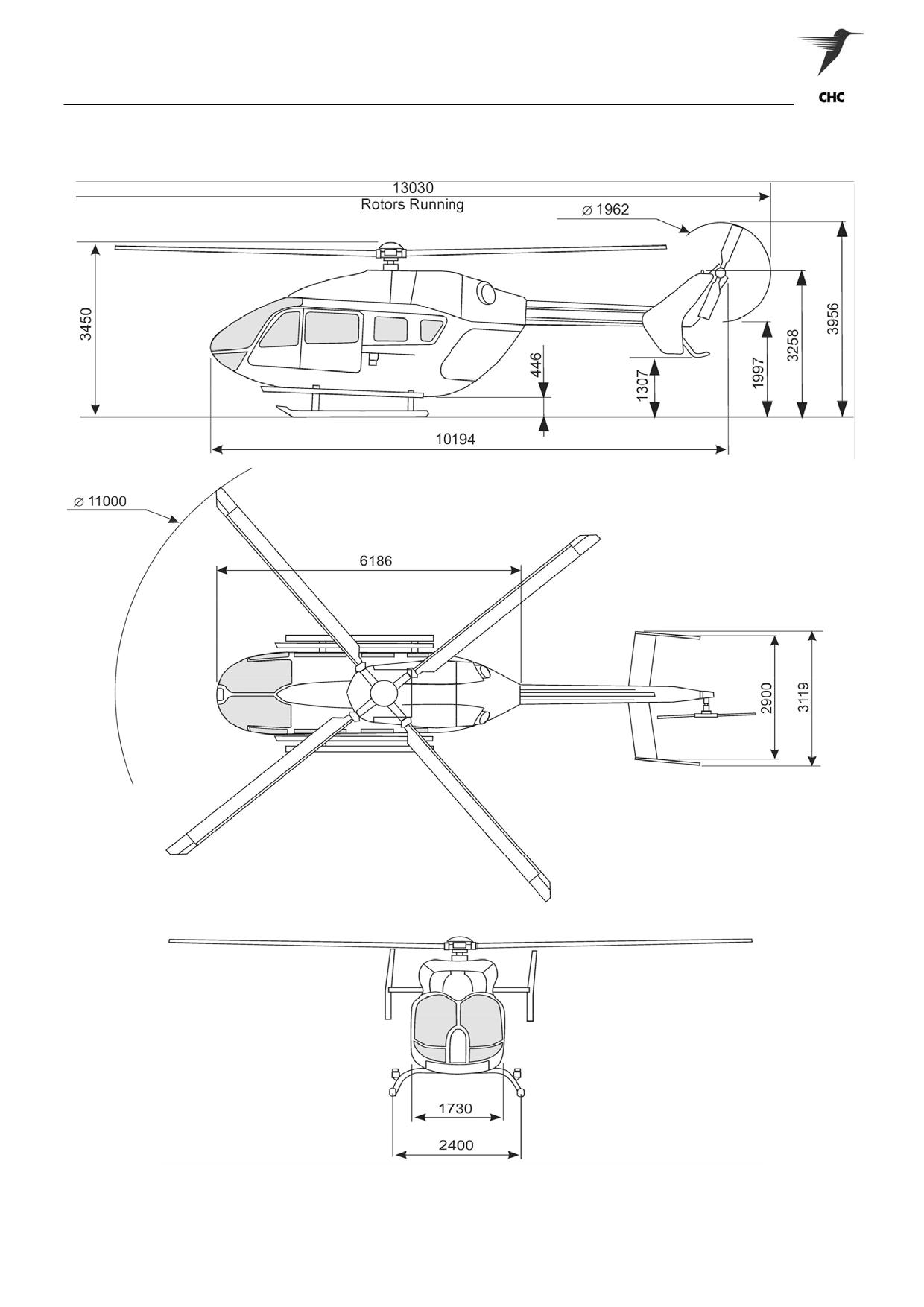
DIMENSIONS AND LIMITATIONS
Figures 1-2 Dimensions
ASNSW EC145 Cabin Staff Training Notes
Revision 1 - July 2010
page 3 of 34
Aircraft Description
Internal dimensions
Performance (ISA) (up to)
- Cabin:
- VNE
150 Kts
• length
3.45 m
- Hovering IGE at MTOW …
2925 m (9600 ft)
• width
1.57 - 1.40 m
- Hovering OGE at MTOW
770 m (2530 ft)
• height
1.28 - 1.23 m
- Rate of climb at MTOW
8.1 m/s (1600 ft/1’)
• volume
6.04 m³
- Service ceiling (AEO at MCP)
5240 m (17200 ft)
• floor resistance ……
600 kg/m2
- Operating temperature ………...………
-45°C to +50°C
• normal density seats
8
• high density seats
10
Fuel
- Tank Capacities (Main & Supply)
694 kg / 867.5 lts (1530 lb)
External dimensions
- Width:
Hydraulic system
• rotors turning
11.0 m
- Operating pressure
103 bar
• without rotors (stabilizer span)
3.12 m
- Length:
Main rotor
• rotors turning
13.0 m
• without rotors
10.2 m
- Type
Rigid rotor system
- Height:
- Diameter
11.0 m
• overall, rotors turning
3.96 m
- Number of blades
4
- Clearances:
- Rpm (100%)
VARTOMS
• MR to ground, rotors turning
3.45 m
- Shaft tilt (forward)
5°
• TR to ground, rotors turning
2.0 m
- Direction of rotation
CCW, viewed from above
Noise (ICAO Annex 16 / FAR part 36)
Tail rotor
- Flyover
87.2/87.2 db
- Type
Semi-rigid system
- Approach
91.3/91.3 db
- Diameter
1.96 m
- Take-off
88.0/87.9 db
- Number of blades
2
- Rpm (100%)
VARTOMS
Weight
- Direction of rotation
CW, viewed from left
- Basic empty (Standard Configuration) ..…….……………. 1792 kg
Engine
- Minimum flyable
1750 kg
- Take off
3585 kg
- Manufacturer
Turbomeca
- Model
Arriel 1E2
Landing gear
- Type
Free turbine turboshaft
- Average fuel consumption (MTOW)
254 kg/hr
- Skid width
2.40 m
- Length
1.19 m
- Ground Clearance:
- Height ……………
0.70 m
• Front Cross tube
506 mm
- Width ………………………………………………………… 0.49 m
• Aft Cross tube
390 mm
- Weight (dry)
125 kg
- Slope Limitation:
• Ground sloping down to the left …...…………………….. Max. 11°
Transmission ratings
• Ground sloping down to the right …...…………...………... Max. 6°
• Ground sloping nose up …………………………...……….. Max. 8°
- AEO Take off power (TOP)
776 kW (1040 shp)
• Ground sloping nose down (if terrain allows) ...…...……... Max. 8°
- AEO Max continuous power (MCP)
632 kW (848 shp)
- OEI 2.5 min power
551 kW (739 shp)
- OEI Max continuous power
404 kW (542 shp)
ASNSW EC145 Cabin Staff Training Notes
Revision 1 - July 2010
page 4 of 34
Aircraft Description
3.
STRUCTURE
General
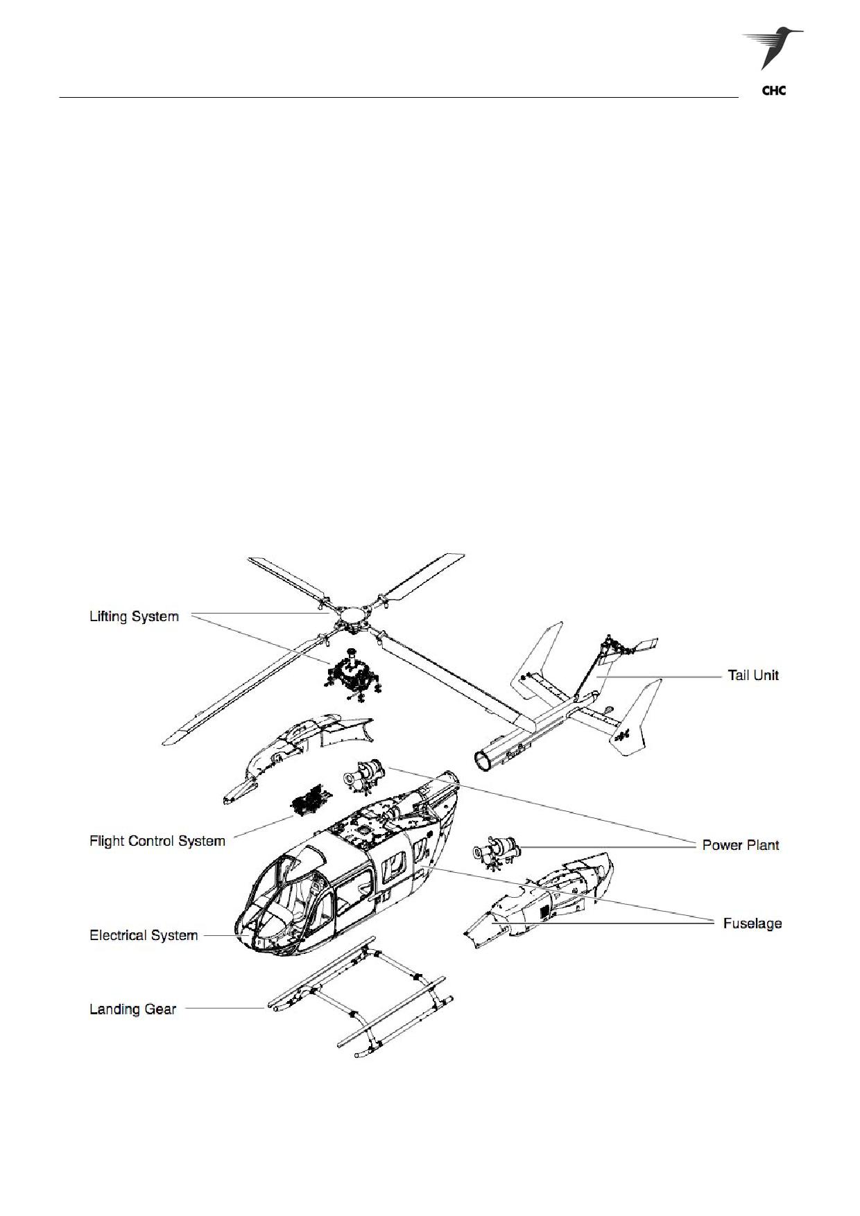
The fuselage’s primary structure consists mainly of sheet metal. The cabin frame, bottom shell, doors,
engine cowlings and access panels are made of composite material
The cockpit, the front section of the fuselage, includes the pilot (RH) and the co-pilot (LH) side by side
seating positions, adjustable crashworthy seats, transparencies (windows), the instrument panel, flight
controls, and a forward opening hinged door on each side.
The cabin composes of the middle to rear section of the fuselage. The cabin includes the passenger
seating area, a sliding door on each side, the floor fuel tanks housing, the transmission and engine deck.
The tail boom mounting cone, the final part of the fuselage, is where the tail unit attaches to the main
fuselage structure.
The remaining parts of the EC145 structure, includes;
• Lifting System
• Power Plant
• Flight Control System
• Cowlings & Fairings
• Tail Unit
• Landing Gear
Figure 1-3 EC145 Structure
ASNSW EC145 Cabin Staff Training Notes
Revision 1 - July 2010
page 5 of 34
Aircraft Description
Doors and Windows
General
The helicopter fuselage is fitted with six doors to provide access to the cockpit, cabin and cargo
compartment.
The entrance doors are:
• Two cockpit doors
• Two passenger doors
• Two clamshell doors
Cockpit doors
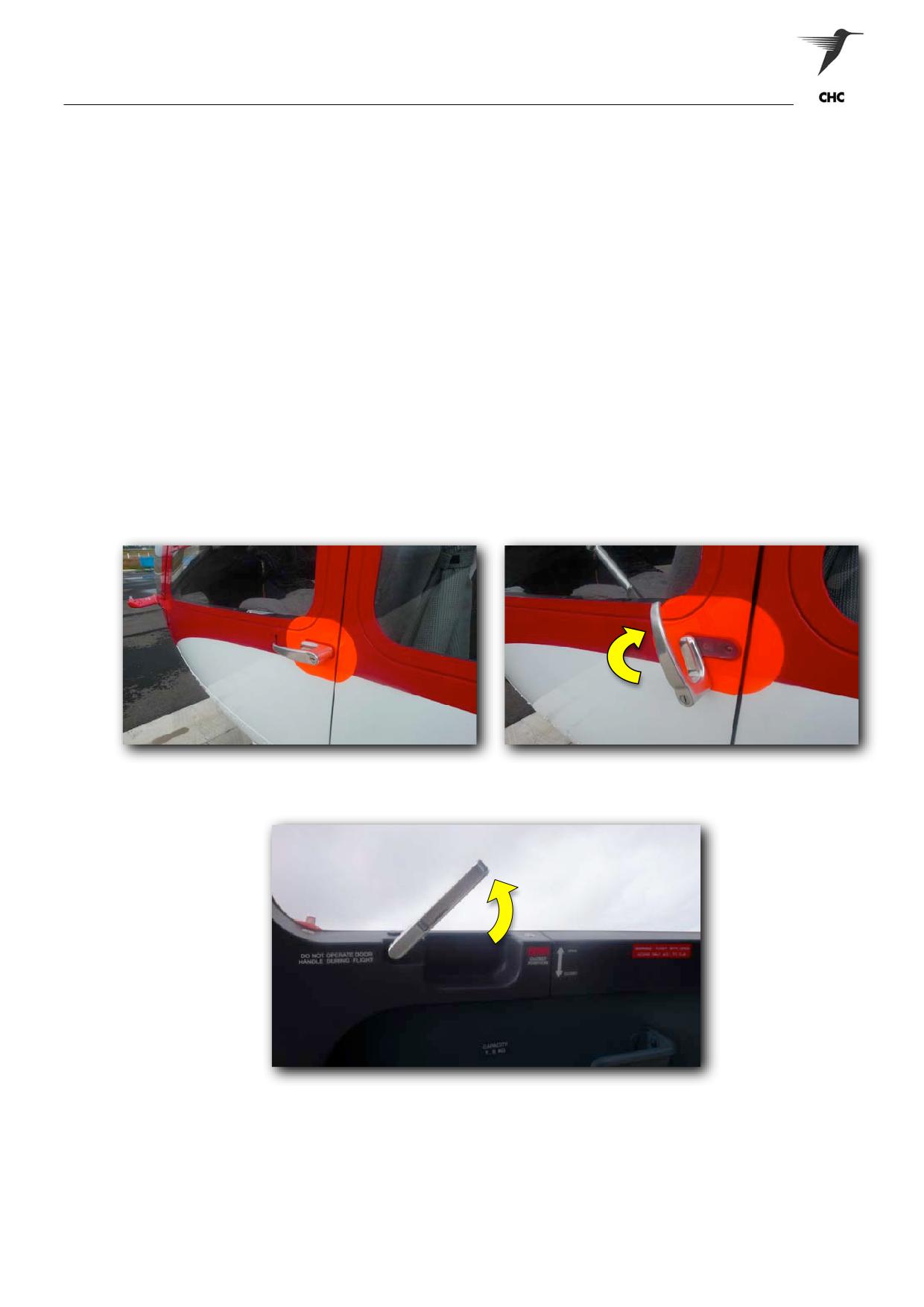
Access to the cockpit is provided on each side through large doors, which are hinged on the forward edge
(Figure 1-4). A crew entrance step is built into the skid landing gear. The cockpit door windows incorporate
a small sliding window, where it can be held by friction in the selected open position on the rails. The rear
part of the doors contains the locking mechanism, consisting of the exterior and interior door handles.
Integrated locks in the outer handles can lock the cockpit doors.
Figure 1-4A Cockpit Door (Locked)
Figure 1-4B Cockpit Door (Unlocked)
Figure 1-4C Cockpit Door Internal (Unlocked)
NOTE:
Caution must be exercised when closing the cockpit doors as not to allow them to slam
shut
against the fuselage. Positive control of the door must be maintained at all times
and the handle opened against spring pressure whilst closing the door as not to damage
door lugs.
ASNSW EC145 Cabin Staff Training Notes
Revision 1 - July 2010
page 6 of 34
Aircraft Description
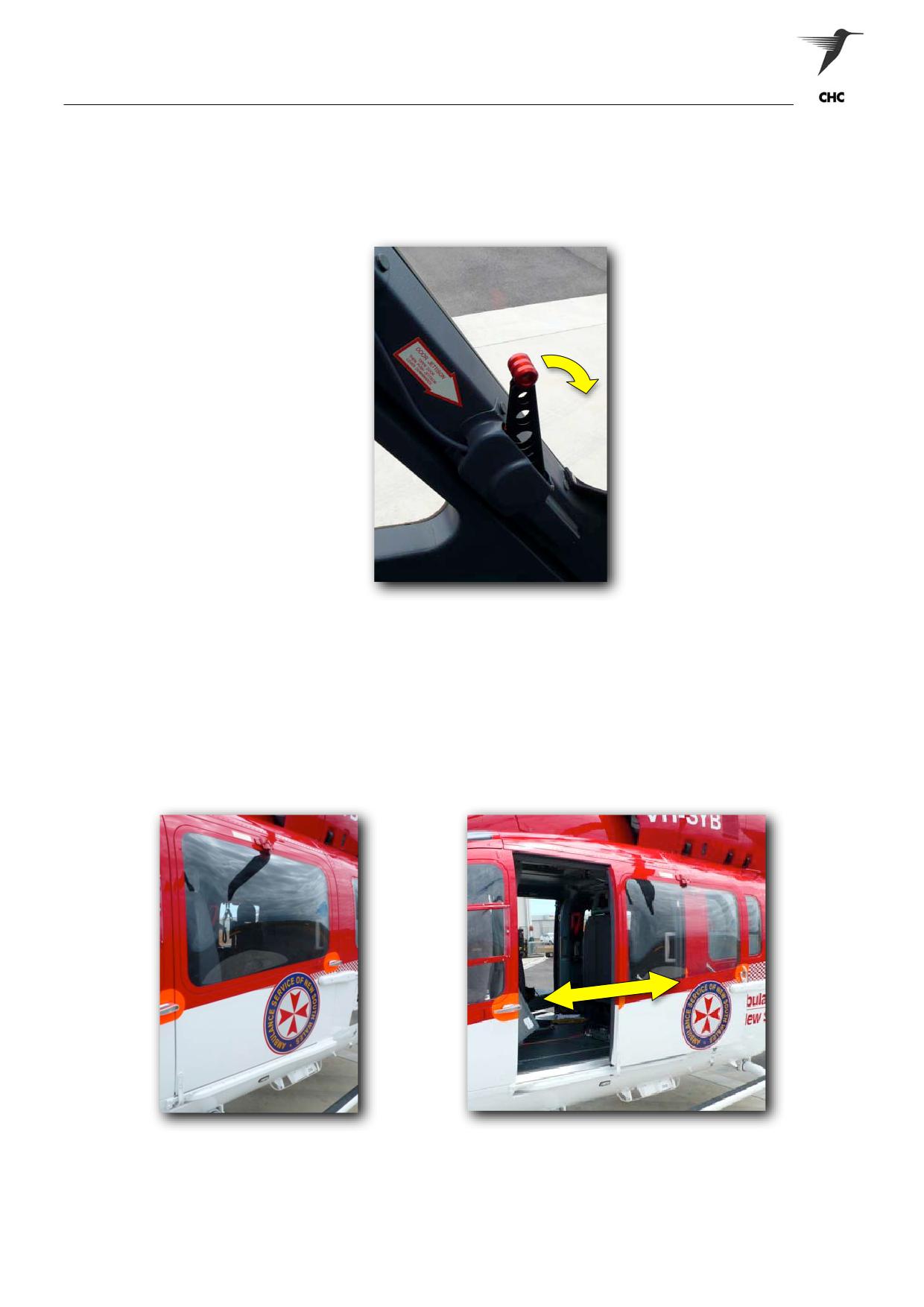
In an emergency, the cockpit doors may be jettisoned by opening the door handle first. Identify jettison
lever (A-Pillar) and push downwards; the lever pulls the cable to unlock the pins from the collar bushings,
the cockpit door can be pushed out from the cabin structure. The jettison lever is safe-tied with snap wire to
prevent accidental operation. (Figure 1-5)
Figure 1-5 Emergency Jettison Lever
Sliding Doors
The sliding plug style door (Fig 1-6) on each side is opened and closed with the exterior door handle or the
interior door handles, and their associated lock mechanism. The sliding door can be secured in either the
closed/opened position, or an intermediate open position by the means of an integrated locking pin.
Located on the internal upper forward leading edge allows the crew to select and lock the door in the half
open or fully open position.
Figures 1-6 Sliding Cargo Doors
ASNSW EC145 Cabin Staff Training Notes
Revision 1 - July 2010
page 7 of 34
Aircraft Description
NOTE:
Prior to opening the sliding doors, it is critical that maintenance access steps and the fuel
filler hatch are secured. In addition the deck on the sponsons is to be clear of obstructions.
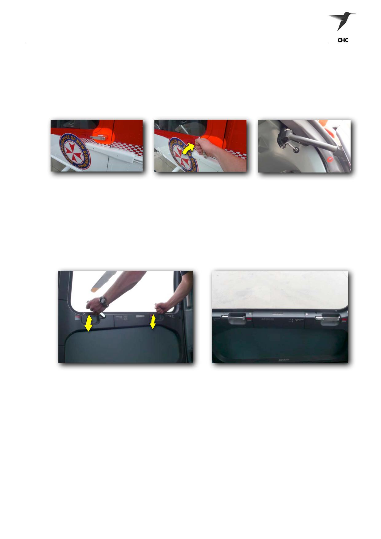
Opening of the sliding doors externally requires the door firstly to be unlocked (Fig 1-6A), where the handle
(located at the rear of the door) can be pulled upwards (Fig 1-6B). Which allows the door to move out from
the fuselage and tracked aft to the desired locked position (Fig 1-6C). .
Figure 1-6A
Figure 1-6B
Figure 1-6C
Closing the sliding doors externally may require the operator to firstly unlock the door from the selected
position by releasing the interior locking pin. Whilst rolling the door forward, the operator must rotate the
handle rearwards (to recess the locking lugs) gently allowing the door to “plug in” then rotate the handle
down into the locked position.
Opening the door from the inside requires the operator to pull upwards on the internal forward or aft handle
to the vertical position, then allowing the door to un-plug and track back to the desired locking position.
Figure 1-6D
Figure 1-6E
Closing the sliding door from the inside requires the operator to initially unlock the door from the locking
pin. When tracking the door forwards, it’s recommended the operator grabs both handles in the vertical
position and ‘plugs’ the door closed (Fig 1-6D). Once plugged, rolling forwards on the handle(s) to the
horizontal position will complete the locking (Fig 1-E).
NOTE:
Do not attempt to force the doors closed if resistance is experienced. Stop, look and
endeavour to identify the problem, or ask for assistance.
CAUTION:
The IAS must be below 60Kts (paying particular notice to crew and cabin security) prior to
opening the cabin sliding door. Aerodynamic pressure assists greatly in the opening of the
doors in flight, hence the need for total positive control of the door. It is recommended that
the door be closed as soon as possible upon rotation, as aerodynamic pressure will hinder
the closing of the door as airspeed increases.
ASNSW EC145 Cabin Staff Training Notes
Revision 1 - July 2010
page 8 of 34
Aircraft Description
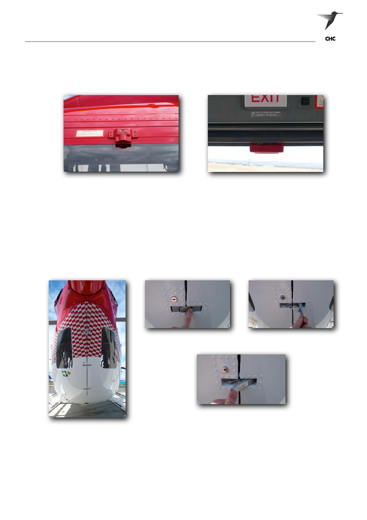
In an emergency situation both sliding doors can be jettisoned either externally or internally. To jettison at
both positions, pull the release handle centrally located at the upper windowsill (Fig 1-7A & 1-7B); followed
by pulling either door handle rewards more than 90° to the open position. This sequence will release the
internal cables, allowing the sliding door to be removed from the cabin structure.
Fig 1-7A (External Release)
Fig 1-7B (Internal Release)
Clam Shell Doors
The Clam Shell doors are designed to allow patients or cargo to enter the cabin effortlessly, due to the
hinged doors expanding wide open and the lowered aft cabin floor.
The Clam Shell doors are constructed from Kevlar composites. Two hinges are attached to the forward
edge of each cargo door by screws, which connect the cargo doors to the main fuselage structure. Three
locking devices are installed on the aft edge of the RH cargo door; and clasp the mating sleeves on the aft
edge of the LH cargo door when the doors are closed. A gas strut as been installed on both doors for
holding open the unlatched cargo doors. The centre latch has a lock and is secured with a key.
Figure 1-8A Opening Latch (1)
Figure 1-8B Opening Latch (2)
Figure 1-8C Closing Latch
Figure 1-8 Clam Shell Doors
NOTE:
Its recommended when opening and closing the doors, the centre latch is fastened initially
when closing or released last when opening. This will ensure the upper and lower latches
align correctly, and alleviate the doors from buckling.
WARNING:
DUE TO SAFETY MEASURES, ACCESS TO CABIN VIA THE CLAM SHELL DOORS IS
PROHIBITED WHILST THE ENGINES ARE OPERATING.
ASNSW EC145 Cabin Staff Training Notes
Revision 1 - July 2010
page 9 of 34
Aircraft Description
Entry and Exit
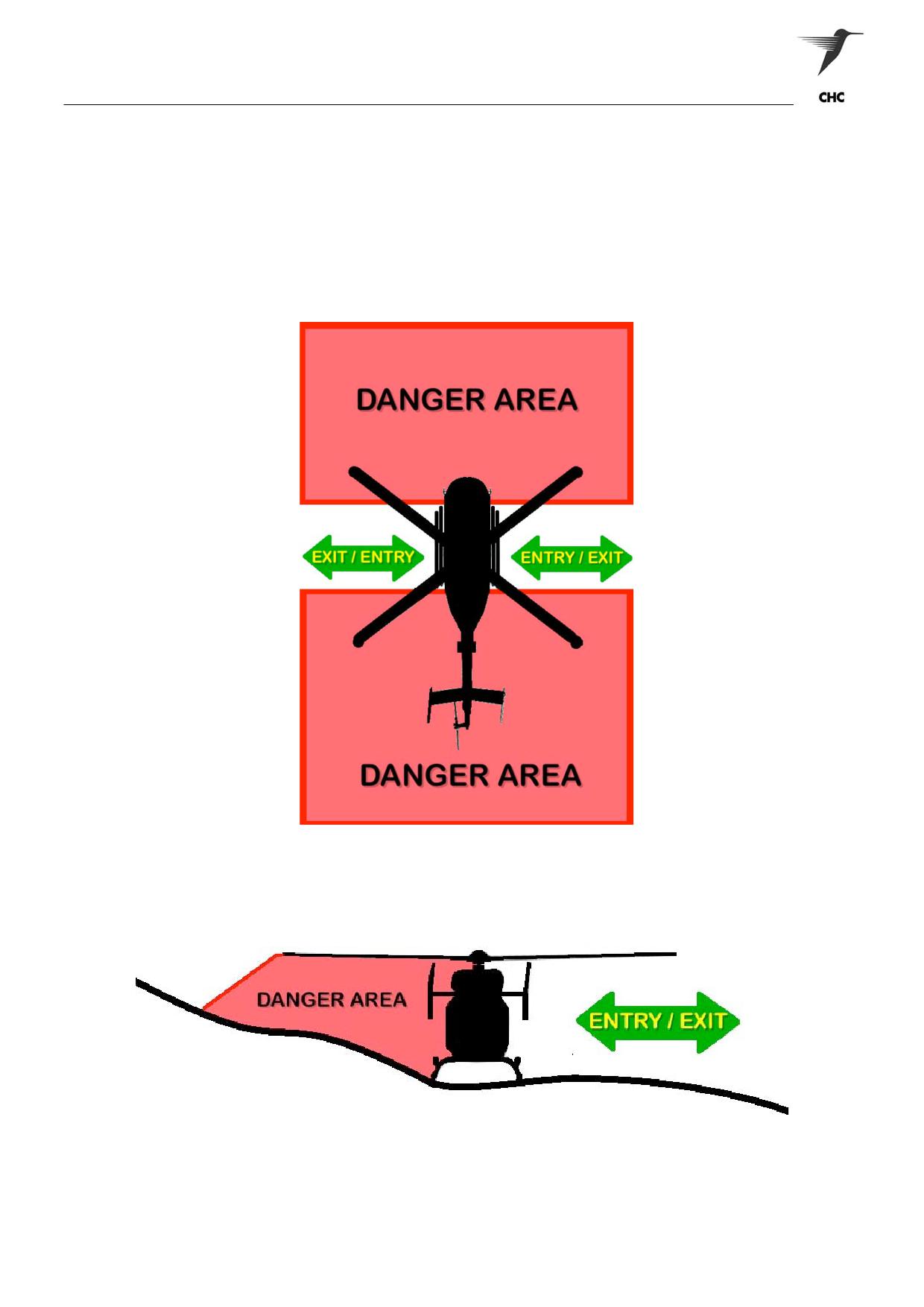
Entry and Exit to/from the aircraft is to be via the 3 and 9 o’clock positions and only after the pilot /
crewman has given a thumbs up signal by day or landing light off then on by night.
Sloping ground will also need to be considered whilst approaching or departing the aircraft, if the situation
occurs; exit and enter from either the 3 or 9 o’clock descending terrain.
All items carried in to or out of the aircraft are to be kept below shoulder height; and secure all loose items.
Figure 1-9 Approach and Departure Path
Figure 1-10 Approach and Departure Path - Sloping Ground
ASNSW EC145 Cabin Staff Training Notes
Revision 1 - July 2010
page 10 of 34
Aircraft Description
Landing Gear
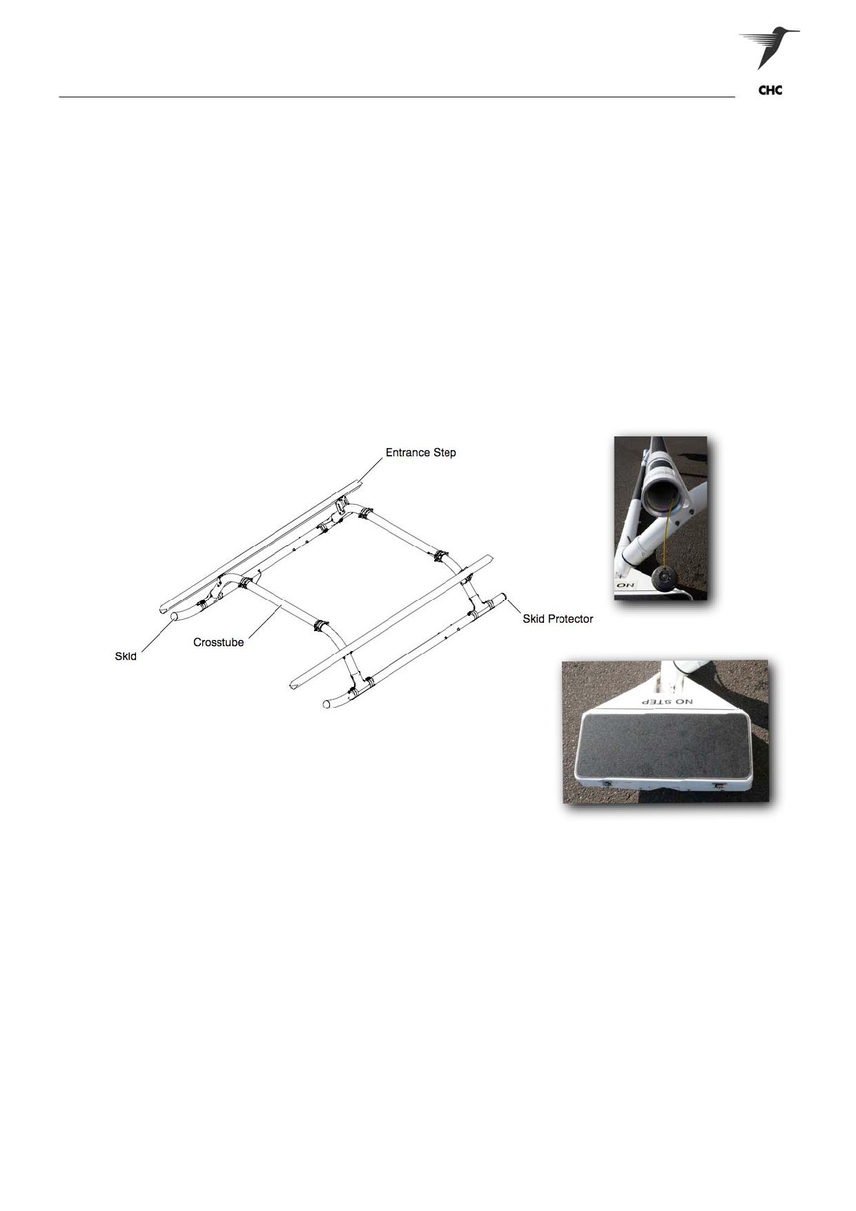
The landing gear assembly consist of two skids and two arched cross tubes of formed aluminium alloy,
fastened together with skid shoes and attaching hardware. The assembly is attached to the lower fuselage
structure with fittings at four points. It carries the weight of the helicopter on the ground and also designed
to absorb landing loads.
In its basic configuration, the landing gear is equipped with parallel skids for landings on prepared surfaces.
A skid track of 2.4 m provides the helicopter with good stability on the ground. Two entrance steps, which
are cross tube-mounted above the skid shoes, are provided to give boarding assistance to crew members
and passengers.
To meet changing ground conditions, the landing gear has been fitted with Settling Protectors, where it
prevents the aircraft sinking into soft surfaces. Whilst attached to Left-hand entrance step is a Multi-
Purpose Carrier for the Nitesun.
Due to the limited cabin space for non-medical equipment, the manual fuel-drum pump has also been
incorporated into the landing gear’s entrance step tube (Fig 1-11B) and Settling Protector (Fig 1-11C)
Figure 1-11B
Figure 1-11A Landing Gear
Figure 1-11C
4
FLIGHT CONTROLS
General
Adjusting the angle of incidence of the main rotor blades and the tail rotor blades controls the flight of the
EC145.
Three types of controls are necessary to fly the helicopter:
• Collective control
• Cyclic control
• Tail rotor control.
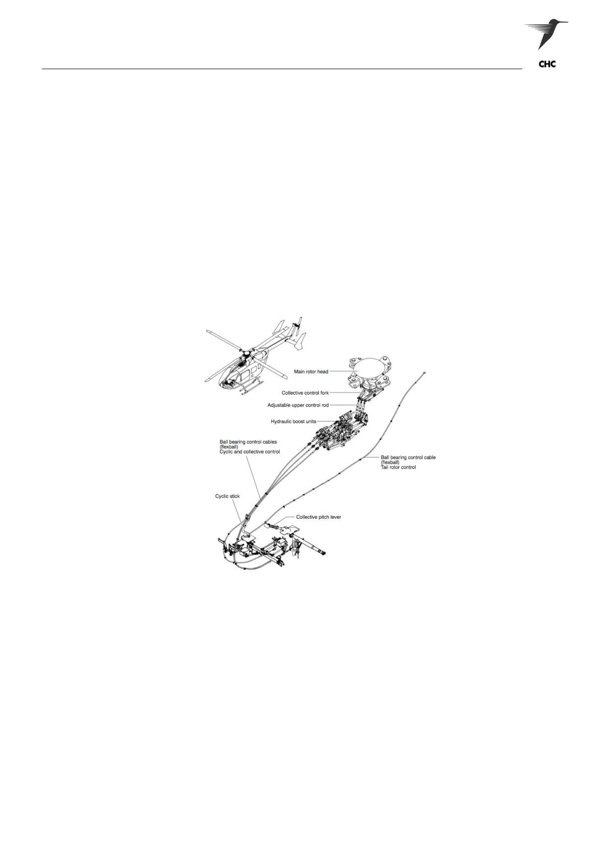
The control inputs from the pilot are transferred via ball bearing control cables to the hydraulic unit, where
they are boosted and embedded to the mixing lever assembly. The mixing lever assembly transfers the
inputs to the swash plate and from there directly to the main rotor blade.
ASNSW EC145 Cabin Staff Training Notes
Revision 1 - July 2010
page 11 of 34
Aircraft Description
Collective Control
Changing the angle of incidence equally on all four main rotor blades increases or decreases the main rotor
thrust. This is called collective control.
Cyclic Control
Adjusting this angle periodically within one rotation of blade tilts the resulting lifting force, caused by all four
blades, out of the vertical axis, i.e. a horizontal force component is created. The helicopter will tilt and move
in the direction of the horizontal force. This is called cyclic control. Cyclic control consists of lateral control
(LH and RH movement) and longitudinal control (forward and backward movement).
Tail Rotor Control
The tail rotor control is in principle the same as the collective control of the main rotor system. Adjusting the
angle of incidence of the two blades collectively varies the thrust, reacting against the main rotor torque.
The helicopter stands still in hover, if these two forces are equal. If not, the helicopter will turn around its
yaw axis.
Figure 1-12 Flight Controls
5
WEIGHT AND BALANCE
General
Proper weight and balance control to ensure that the helicopter CG is within prescribed limits is essential.
Failure to load the helicopter so that it is within CG limits and then maintain helicopter CG within allowable
limits during flight may result in insufficient control capability and unsafe flight conditions.
All calculations to determine helicopter CG are based on the weight of items loaded on the
helicopter, and the item’s location in the helicopter in relation to the reference datum lines.
ASNSW EC145 Cabin Staff Training Notes
Revision 1 - July 2010
page 12 of 34
Aircraft Description
6
POWERPLANT
Introduction
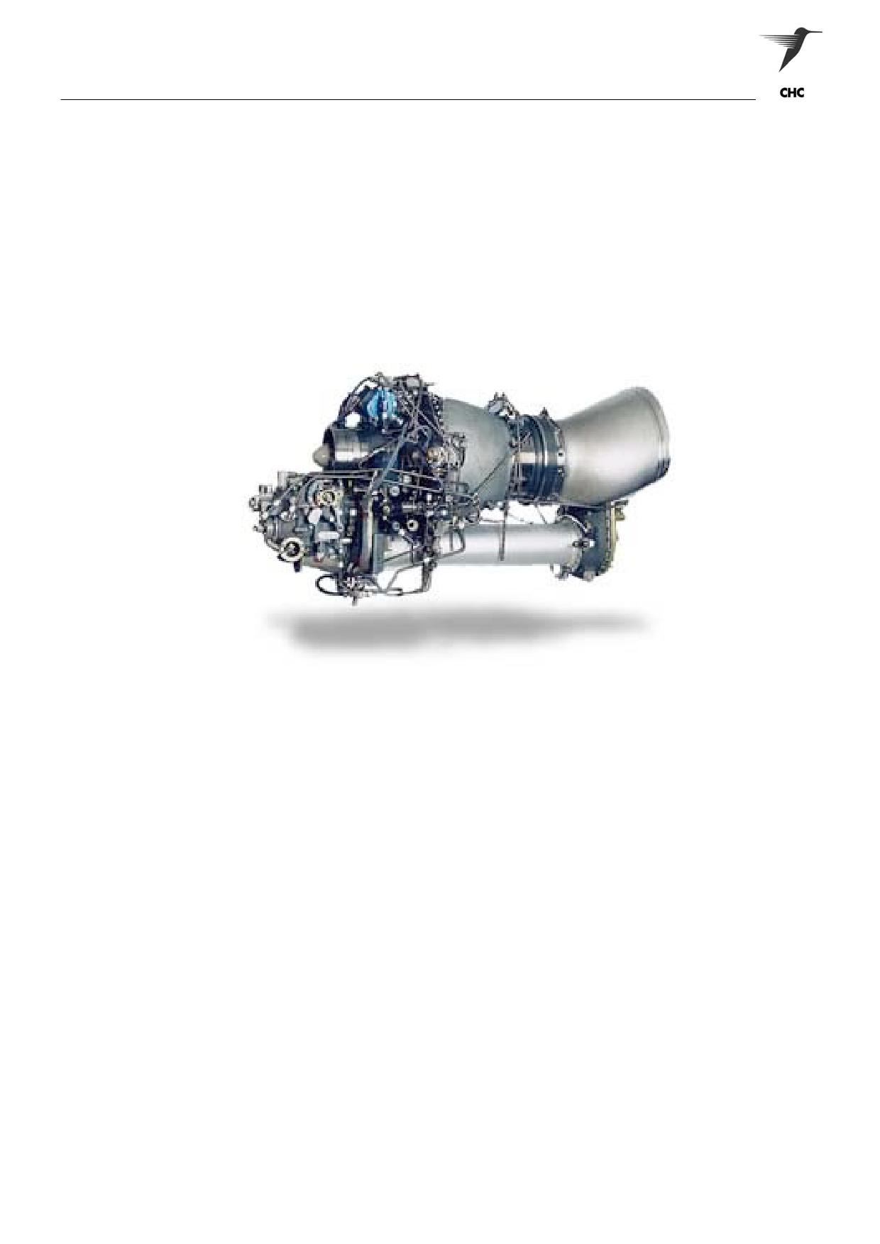
The helicopter is powered by two Turbomeca ARRIEL 1E2 turbo shaft engines, which are of the free
turbine type. Engine power is transmitted to the main transmission via independent drive systems. The
twin-engine reliability is complemented by a fully separated fuel system, a tandem hydraulic system, dual
electrical systems and a redundant lubrication system for the main transmission.
The engines are located in separate fireproof compartments aft of the main transmission and above the
passenger/cargo compartment. The engines are turbo shafts, with single-stage axial and centrifugal
compressors, annular combustors, a two-stage gas producer and a single-stage free power turbine.
Figure 1-13 Turbomeca Arriel 1E2
General
The engines are mounted side by side on the engine deck with the left engine (facing forward) designated
as No. 1 and the right engine as No. 2.
Each engine is equipped with its own air management, fuel, starting and ignition, lubrication, and fire
protection systems.
The engines may be started using either airframe battery power or external power, and are capable of each
producing 776 kW (1040 shp) at Take off power (TOP) under All Engines Operating (AEO) ISA.
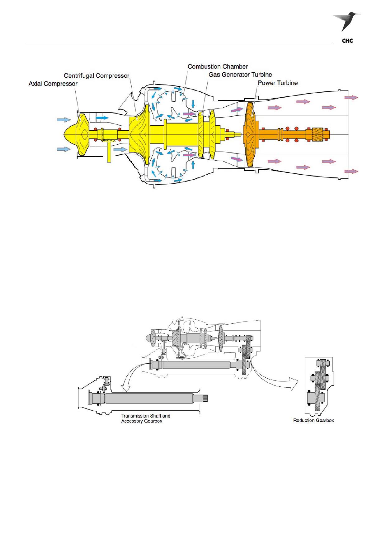
Engine Operation
Air, drawn in through the engine air inlet, is compressed and directed to the combustion chamber. Fuel is
added and ignited to produce hot exhaust gas, which is directed against a turbine wheel.
Exhaust gas exiting the N1 turbine wheel is directed against another turbine wheel, which is connected by
shafting to the input module of the main transmission.
Each engine is started and operated separately. Sprague clutches allow either one or both engines to be
disengaged from the main transmission in the event of an engine failure to allow for auto-rotative descent.
ASNSW EC145 Cabin Staff Training Notes
Revision 1 - July 2010
page 13 of 34
Aircraft Description
Figure 1-14 Turbomeca Arriel 1E2 Cross section
Gearbox - Reduction & Accessory Assembly
The reduction gearbox is the aft supporting structure of the engine. The gas supplied from the gas
generator is directed to the power turbine, which drives the reduction gearbox. In the reduction gearbox
the RPM is reduced, the torque measured and the power transmitted forward to the power output flange.
The accessory gearboxes are mounted to the forward end of each engine, where its primary operation is to
drive the hydraulic pump and oil cooling fan.
Figure 1 - 15 Reduction & Accessory Gearboxes
ASNSW EC145 Cabin Staff Training Notes
Revision 1 - July 2010
page 14 of 34
Aircraft Description
7
POWERTRAIN
Introduction
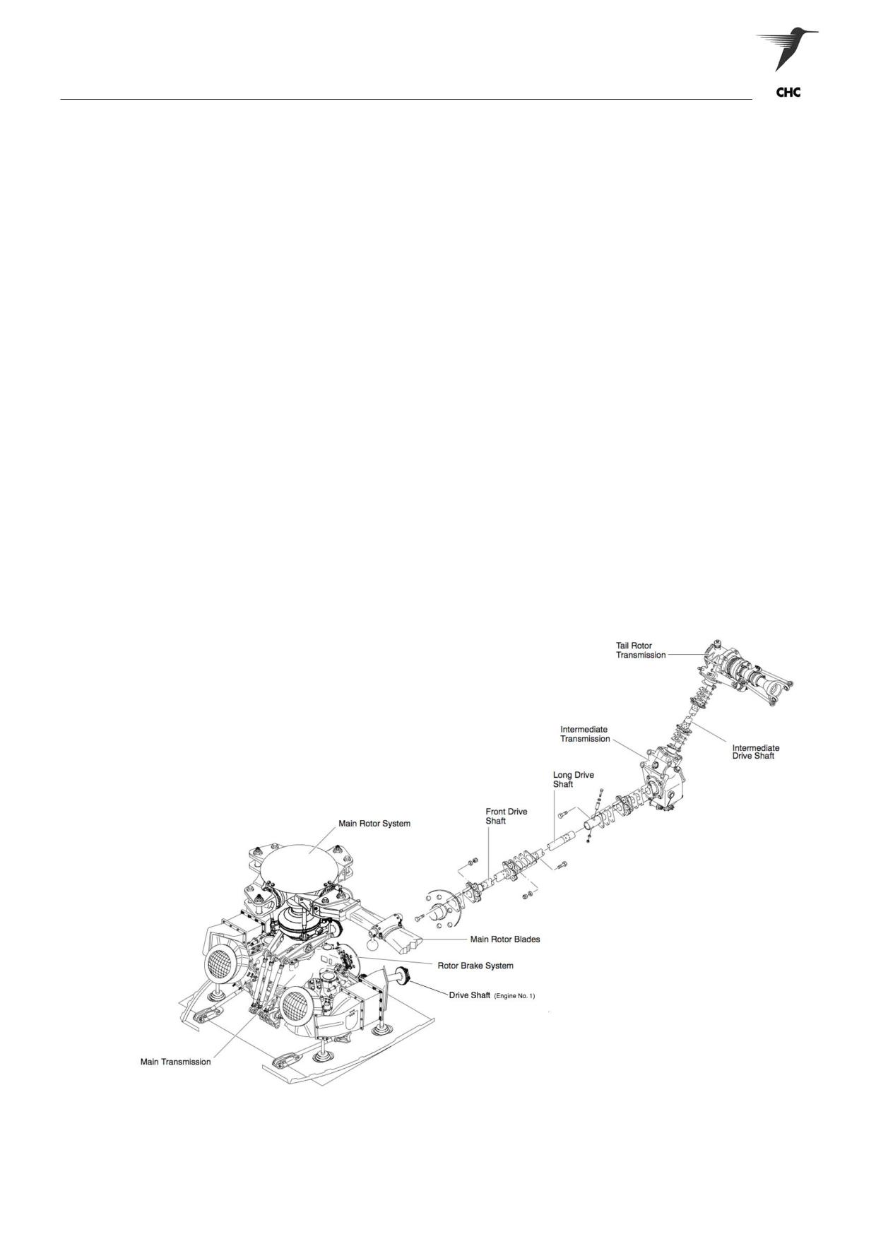
The powertrain of the EC145 distributes engine power to drive the helicopter’s main and tail rotor systems
and numerous required subsystems. The powertrain includes the main drive shaft, main transmission,
main rotor mast, and tail rotor drive system. The tail rotor drive transmits the power from the main rotor
transmission to the 50° angle intermediate transmission through the front short drive and the long drive
shaft. From there it is routed upward to the 90° angle tail rotor transmission by the intermediate shaft. Both
gearboxes are oil splash lubricated (Fig 1-16).
General
Engine power is transmitted to the main transmission via the input modules. The transmission, through
additional gearing, drives the tail rotor drive system.
Main Transmission
The main transmission is a two-stage flat design gearbox. The first stage, also called the input bevel gear
stage, consists of engine drive shafts, free-wheel clutches, bevel gear shafts and bevel gears to deflect the
power flow. The second stage, also called collector gear stage, consists of a collector gear, bevel gear
shafts and bevel gears that form the interface to the input bevel gear stage. The main transmission
provides output power for the main rotor, the tail rotor, the hydraulic system pumps and the oil cooling fans.
A freewheeling unit, located at each main transmission input, permits either one or both engines to be
disengaged from the main transmission. The freewheeling units will disengage both engines during
autorotation, one engine for single engine operation, or any time engine drive shaft RPM is below the RPM
of the driven shaft in the main transmission.
Figure 1-16
Power-train System
ASNSW EC145 Cabin Staff Training Notes
Revision 1 - July 2010
page 15 of 34
Aircraft Description
8
CABIN LAYOUT
NOTE:
Cabin layout descriptions within this section may vary when compared to a non-winch
equipped aircraft.
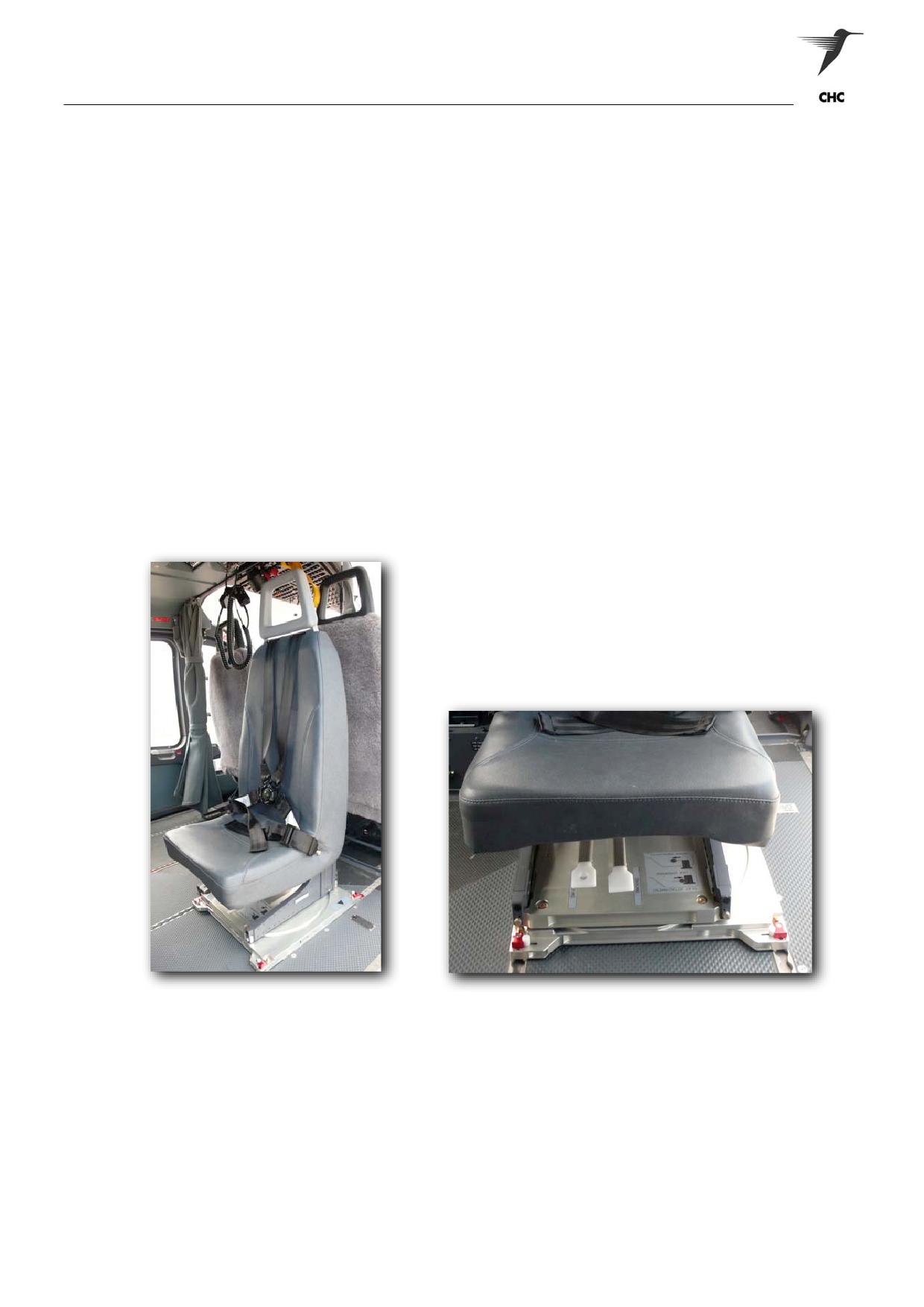
Cabin Seating
The rear cabin comprises two Aerolite swivel seats and one removable fold-down crew seat. The Aerolite
seats comprise a four-point harness and inertia reel restraint system. The Aerolite crew seat will track fore
and aft, and will also swivel by lifting the appropriate handle. Should the handle be released during the
swivel action, the seat will lock itself in position every 30 degrees.
For the Aerolite seats to track and swivel properly, it is imperative that the aircraft floor be regularly cleaned
and vacuumed free of dirt and dust.
NOTE:
Do not force the seats into position - if difficult to move, investigate the problem or ask for
assistance from the Aircrew. Look for obstructions prior to swivelling the seats - i.e. Winch
Pendants, Nav Bags, and Hand-Held Searchlights etc. Track Seats further away
from the obstruction if required prior to swivelling.
CAUTION:
Ensure the Aerolite swivel seat have engaged and locked correctly within the floor
tracks following their repositioning.
Figure 1-17 Aerolite Swivel Seat
Figure 1-18 Operating Handles - Swivel / Track
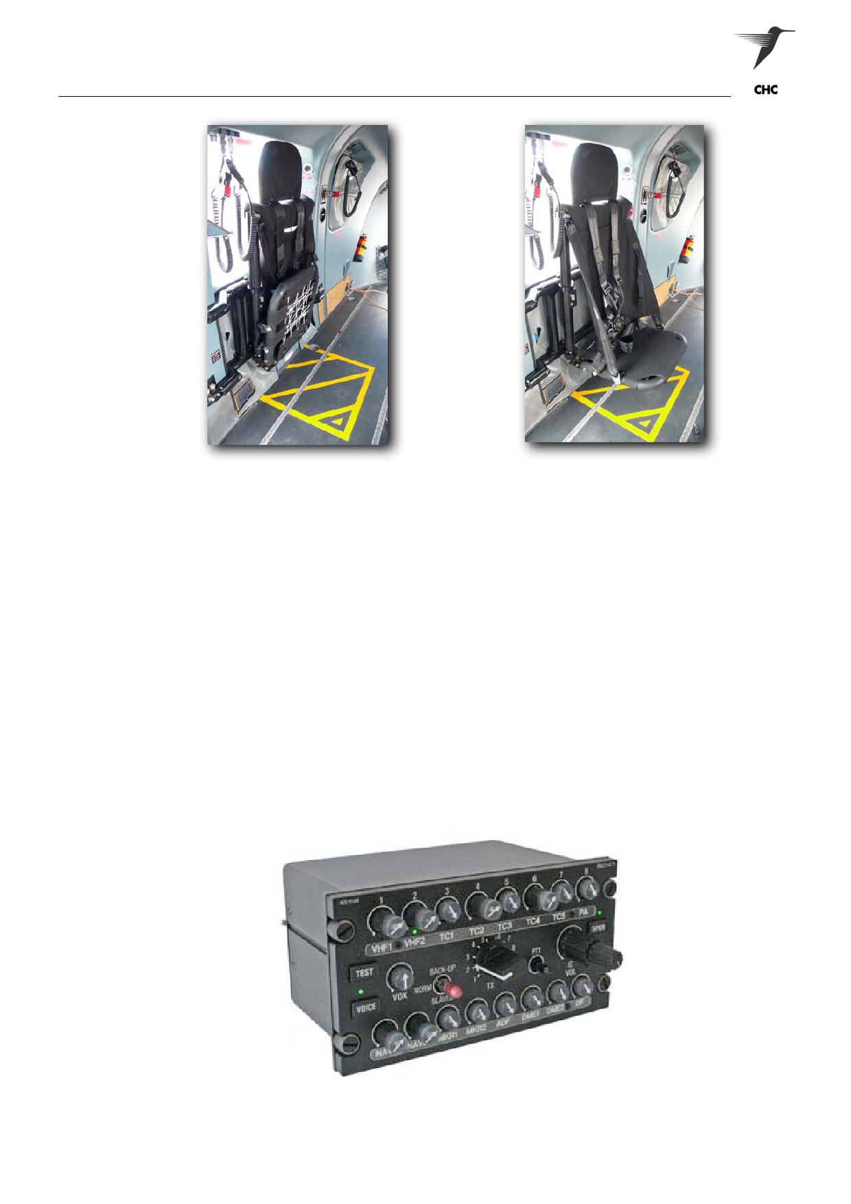
The fold-down side facing troop seat and interface frame can be installed and removed via the quick
release seat studs at the three mounting locating. When folded vertically it provides full-allocated tracking
for the RHS medical crew seat.
WARNING:
ENSURE CABIN CONFIGURATION ALLOWS EASY EMERGENCY EGRESS FROM
THE SIDE FACING SEAT. THAT IS, NO OBSTRUCTIONS THAT CAN PREVENT
RAPIDE EVACUATION FROM THE AIRCRAFT - NO STOWAGE UNDER SEAT.
ASNSW EC145 Cabin Staff Training Notes
Revision 1 - July 2010
page 16 of 34
Aircraft Description
Figure 1-19 Fold-Down Side Facing Troop Seat (Retracted/Extended)
Communications
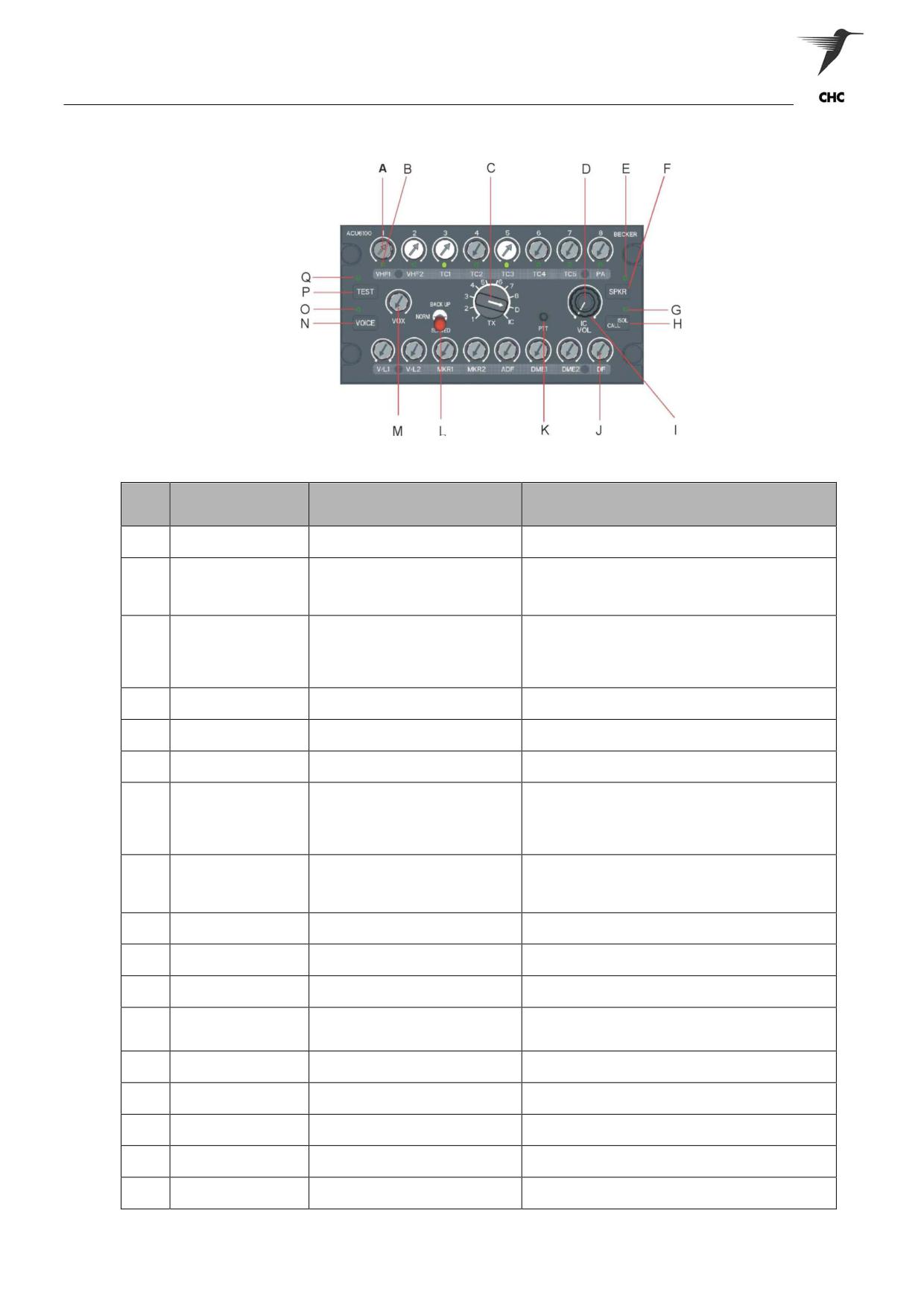
The EC145 is fitted with the Becker DVCS 6100, which is a digital audio system (Fig 1-???) There are four
(4) Becker audio control units within the aircraft, two are located in the cockpit’s centre console; whilst the
remaining two are located forward of the cabin’s ceiling.
There are seven (7) drop leads located in the rear cabin, six (6) that associated with the two (2) cabin audio
control units. The single drop lead positioned near the winching station (R/H Cabin Door) is restricted for
the ACM use only. The remaining six (6) drop leads are for the cabin staff or passenger use, four (4) have
full RX/TX intercom or radio authority, where the two (2) basic drop lead style are Intercom use only.
The audio control unit incorporates many functions that allow the aircrew to control Intercom or radios for
their required use. Intercom & radio RX volumes can be independently adjusted to comfort, and with the
voice activated intercom function it gives the aircrew the freedom to be hands-free in high workload
periods.
Refer to the placard communications plan as to which selector drives which radio.
Figure 1-20 Becker DVCU 6100
ASNSW EC145 Cabin Staff Training Notes
Revision 1 - July 2010
page 17 of 34
Aircraft Description
ICS - Operating Instructions
Control /
Item
Description
Function
Indicator
8 potentiometer with push-push
On/Off switch for every TX channels and individual
A
TX1 to TX8 controls
switches
volume adjust for audio monitoring
Indication of individual TX channel status
LED on = channel is preselected for transmission
B
TX indicators 1 to 8
8 LED.s (green)
LED blinking = transmission is activated
LED blinking = Selective CALL fast is activated
Position 1 to 8 pre selection of TX channel for
transmission
Transmitter selector
C
Rotary switch with 10 lock positions
Position D selection of 2 predefined TX channels for
switch
dual transmission mode
Position IC intercom PTT mode
D
IC volume control
Potentiometer
Volume adjustment for intercom
LED on = Speaker is on
E
SPKR indicator
LED (green)
LED off = Speaker is off
F
SPKR button
Push-button
On/Off switch for audio monitoring via the speaker
LED on = cockpit and cabin intercom circuits are
isolated
G
ISOL/CALL indicator
Push-button
LED off = cockpit and cabin intercom circuits are
connected
LED blinking = intercom request CALL is active
Cockpit connect or truncate the cockpit and cabin
intercom circuits
H
ISOL/CALL button
LED (green)
Cabin initiates an intercom request CALL if the
intercom circuits are truncate
I
Volume Control
Potentiometer
Main volume control
8 potentiometer with push-push
On/Off switch for every RX channels and individual
J
RX1 to RX8 Controls
switches
volume adjust for audio monitoring
Momentary switch with 2 key
Switch pressed = selected transmitter is keyed
K
PTT switch
positions
Switch released = selected channels are monitored
Position NORM = normal operation
L
BACK-UP switch
Toggle switch with 3 lock positions
Position SLAVED = slave operation
Position BACK-UP = emergency operation
M
VOX level adjustment
Potentiometer
VOX sensitivity selection
On/Off switch for VOICE filter (for configured -RX
N
VOICE button
Push-button
channels)
LED on = voice filter is active
O
VOICE indicator
LED (green)
LED off = voice filter is not active
P
TEST button
Push-button
Activation of IBIT (test function)
LED on = internal self test is running
Q
TEST indicator
LED (yellow)
LED blinking = the internal self test detected an failure
ASNSW EC145 Cabin Staff Training Notes
Revision 1 - July 2010
page 18 of 34
Aircraft Description
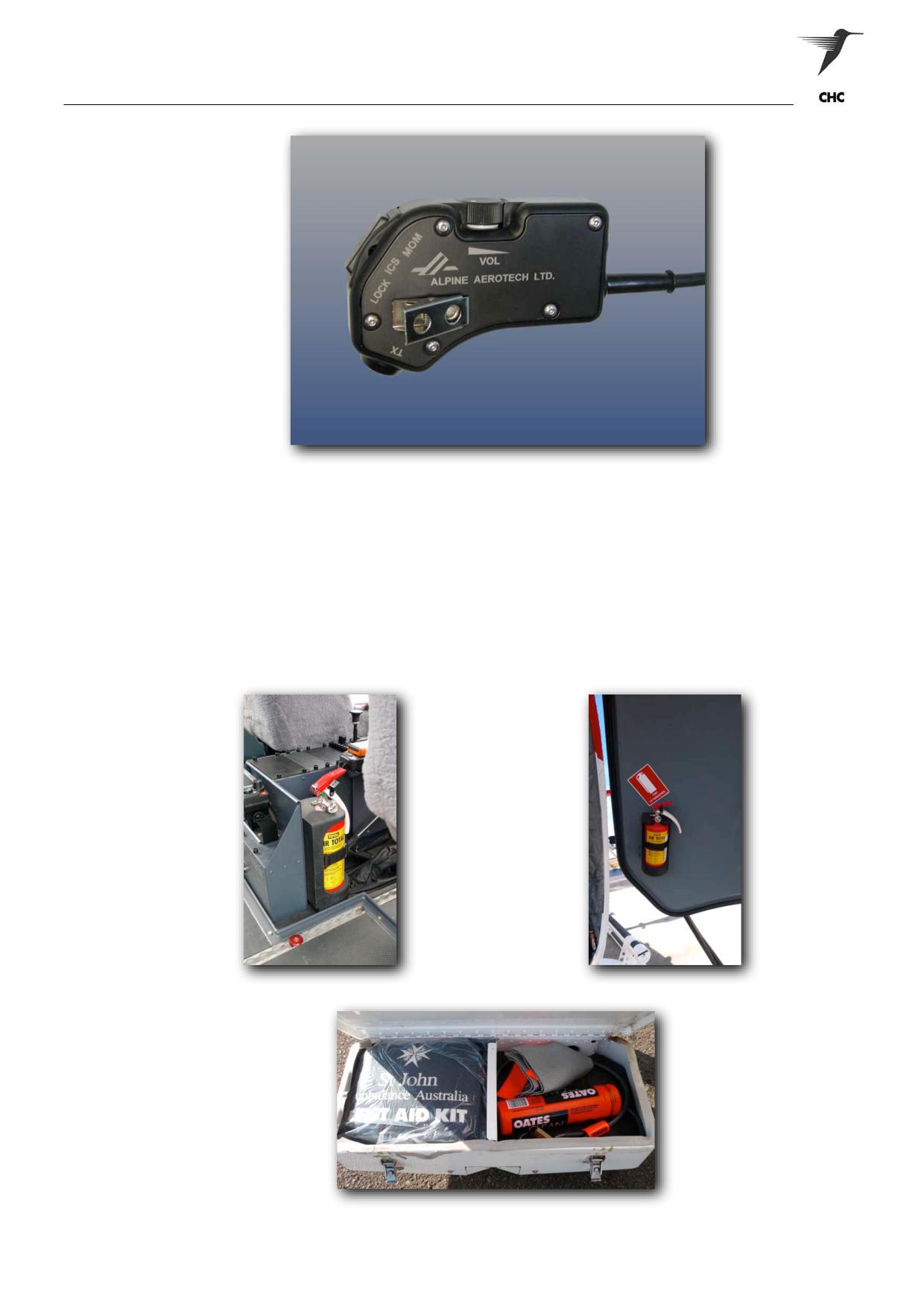
Figure 1-21 ICS Drop Lead
NOTE:
Ensure the correct ICS lead is utilised for the function required. If radios are required
ensure the ICS / TX drop lead is utilised.
Fire Extinguishers and First Aid Kits
The aircraft Halon fire extinguishers are located at the rear right hand side of the centre console (Fig 1-22),
and on the right clam-shell door at the lower hinged section (Fig 1-23). The aircraft first aid kit is located in
the LH Settling Protector Stowage Compartment (Fig 1-24).
Figure 1-22
Figure 1-23
Figure 1-24
ASNSW EC145 Cabin Staff Training Notes
Revision 1 - July 2010
page 19 of 34
Aircraft Description
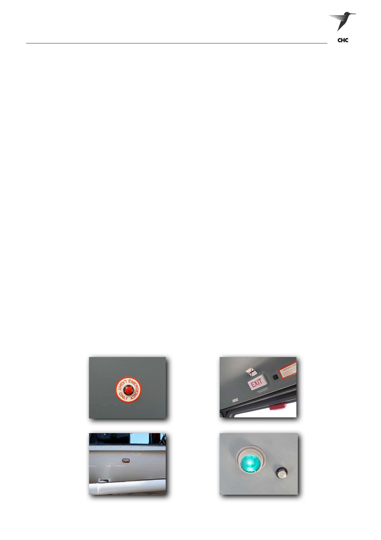
Emergency Lighting
Emergency exit lighting is provided to illuminate the exits, the stairways and the cabin in case of
an emergency. The exit lights are of rectangular shape with a red inscription EXIT, the stairway
and cabin lights do not have an inscription.
The system comprises the following main components:
• Emergency power pack
• Impact switch
• BAT HOR/EX test switch
• EM/EX LIGHT switch
• EM/EXIT LIGHT switch
• Two exit sign lights at the cabin doors, one exit sign light at the co - pilot’s doors, two
stairway lights and three gimbal cabin ceiling lights (NVG compatible).
The impact switch detects acceleration in two axis (up - down, fore - aft). If a hard landing occurs,
the impact switch triggers the switching on of the emergency lighting. The EM/EX LIGHT switch,
located in the overhead panel, has three positions (OFF, ARM, ON) and controls the emergency
lighting.
The emergency lights are OFF if:
The emergency lights are ON if:
-
The switch is in OFF position
-
The switch is in ON position
-
The switch is in ARM position and normal
-
The power supply drops below 12 VDC
operation.
-
The impact switch is activated
-
The EM/EX LIGHT switch is activated
-
The switch is in ARM position and one
door is open.
The EM/EX LIGHT switch is installed approximately to the center of the cabin ceiling. The switch
is fluorescent and can be used by the passengers to switch on the emergency lighting in case of
an emergency, independent of the impact switch function.
WARNING:
ACTIVATION OF THE EMERGENCY LIGHTS FOR ANY MEANS OTHER THAN AN
EMERGENCY IS PROHIBITED
Figure 1-25 Cabin Activation
Figure 1-26 Door ‘Exit’ Light
Figure 1-27 Stairway Light
Figure 1-28 Cabin Gimbal Light
ASNSW EC145 Cabin Staff Training Notes
Revision 1 - July 2010
page 20 of 34
Aircraft Description
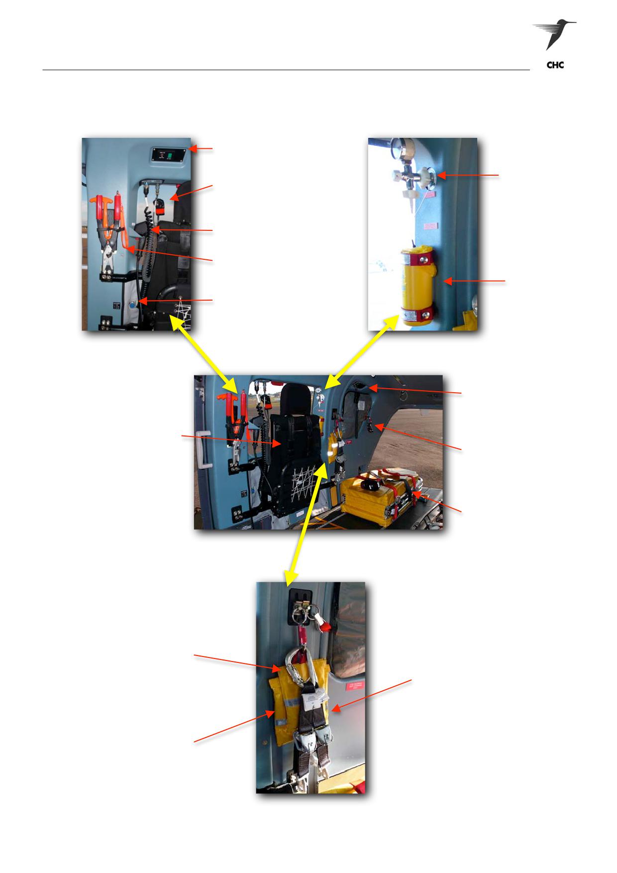
Right-Hand Cabin Layout
Winch ICS Vol / Vox Control
Oxygen Outlet
Winch Operator’s ICS Drop Lead
Winch Pendant
Manual Cable Cutters & J - Knife
Sharps Waste
14 / 28 volt AUX Power Outlet
Rear ICS Outlet
Simula Side-Facing
(Stowage - Folded)
Karabiner(s) / Cargo
Ring(s) Stowage
HeliMods Aircraft Stretcher
(Stowage - Folded)
Weighted Winch Bag
Winch Release (2)
Weighted Message Bag
Figures 1-29 RH Cabin Layout
ASNSW EC145 Cabin Staff Training Notes
Revision 1 - July 2010
page 21 of 34
Aircraft Description
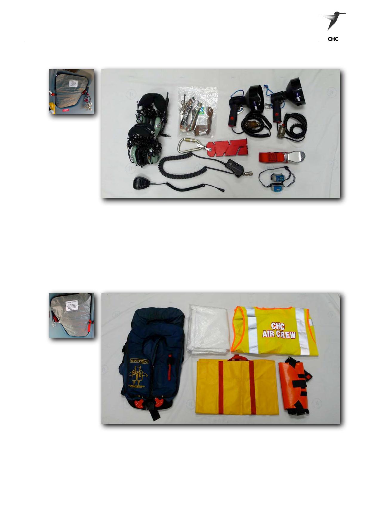
Right-Hand Soft Stowage Compartments
3.
2.
1.
6.
4.
7.
5.
8.
Figure 1-30 RH Soft Stowage Compartment
1. Headsets (2)
5. LED Hand-Lamp (2)
2. Cyalume / Sea-Dye Marker
6. Quick Splice Plate
3. Hand-Held Searchlights (2)
7. ICS Drop Lead
4. Multi-Purpose Restraint
8. ICOM Waterproof Mic/Speaker
Left-Hand Soft Stowage Compartments
2.
3.
1.
4.
5.
Figure 1-31 LH Soft Stowage Compartment
1. Passenger Lifejackets (2)
4. Pedi-Mate (Paediatric Harness)
2. Body-Bag
5. Multi-purpose Winch Bag
3. Aircrew HiVis Vest (2)
WARNING:
5KG MAXIMUM SOFT STOWAGE ONLY WITHIN COMPARTMENTS
ASNSW EC145 Cabin Staff Training Notes
Revision 1 - July 2010
page 22 of 34
Aircraft Description
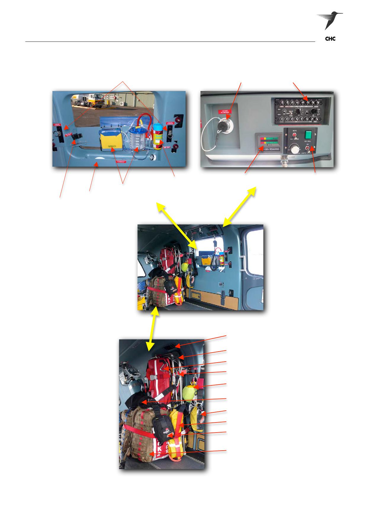
Left-Hand Cabin Layout
Hard-Points - Max. 3kg
Oxygen Outlet
Becker ICS Control Unit
Sharps Waste
Oxygen Monitor
1. Oxygen Alarm Mute - Switch
Suction Unit &Waste Bin
2. ICS Call - Button
3. Medical Lights - Switch / Dimmer
Soft Stowage Compartment - Max. 1Kg
Hand-Held Searchlight Mounts
ICS Drop Lead Outlet
Medevac II Rescue Stretcher
Medical Airway Bag
Equipment Straps (2)
Winch-Hook Float Ball
Medical-Crew PPE Kit
Patient PPE Kit
Rescue Hypo Strop
Medical Thigh-Pouch (2)
Medical Packs (2)
Figures 1-32 LH Cabin Layout
ASNSW EC145 Cabin Staff Training Notes
Revision 1 - July 2010
page 23 of 34
Aircraft Description
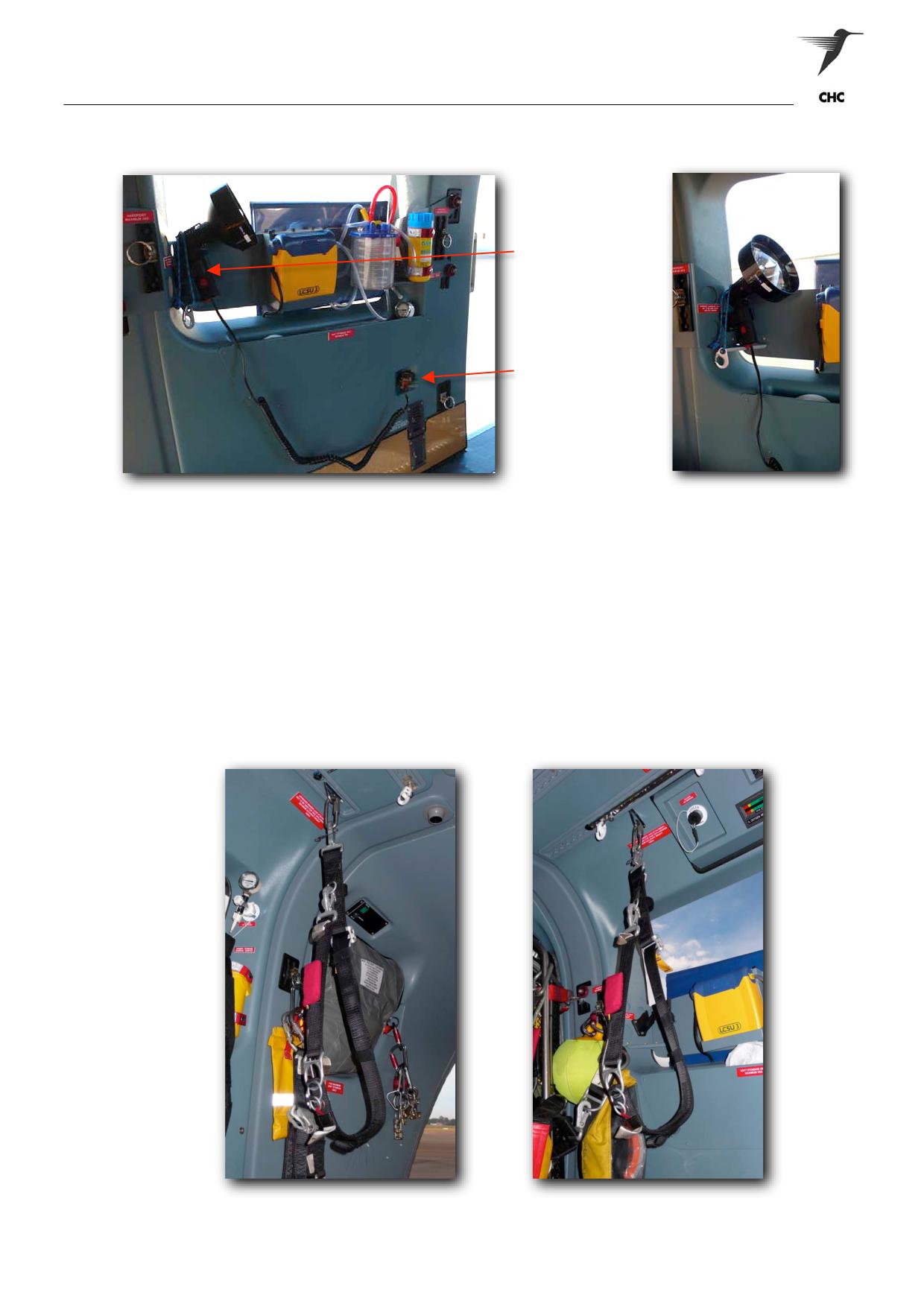
Hand-Held Searchlights
Temporary Searchlight
Mounts
14 / 28 Volt Aux Outlet
Figures 1-33 LH Searchlight Mount
NOTE:
The right hand bulkhead has no mounting bracket; and requires the RH searchlight
to be stowed or secured by an approved restraint when not in use.
WARNING:
TEMPORARY SEARCHLIGHT MOUNTS ARE NOT TO BE USED DURING TAKE-OFF /
LANDINGS
Wander Leads & Attachments
Two Wander Leads are permanently attached on the cabin ceiling, both are adjacent each other and fixed
centrally down the cabin length. The Wander Lead hard-points are each rated to a maximum of 160kg.
Figure 1-34 RHS Wander Lead
Figure 1-35 LHS Wander Lead
ASNSW EC145 Cabin Staff Training Notes
Revision 1 - July 2010
page 24 of 34
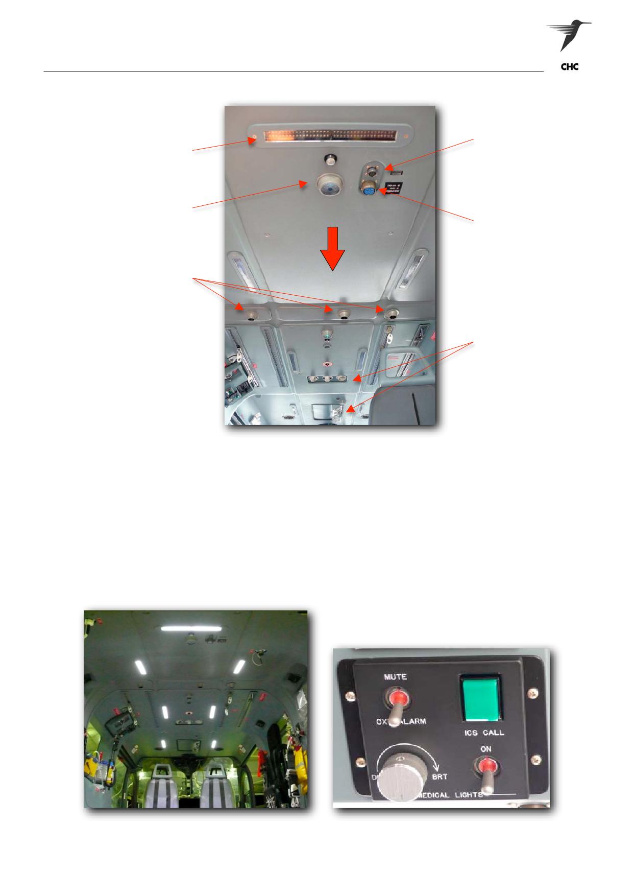
Aircraft Description
Ceiling Layout
Medical Alert Outlet
Medical strip lights
(Bridge)
Emergency / Cargo
Lights
FWD
Bridge Power Outlet
(14 / 28 Volts)
Ram-Air Vents
(Ambient)
Air Conditioning Vents
Figure 1-36 Ceiling Layout
Cabin Medical Lighting
Either the main aircraft battery can power the cabin medical lighting, or the dedicated ‘stand-by battery’.
The stand-by battery is specifically designed to power the cabin medical lights, and reserve the main
aircraft battery when crews require lighting for patient management and associated cabin activities once
landed. A master switch located in the cockpit overrides the cabin medical lights switch and dimmer
(Figure 1-38). The aircraft Captain or Aircrewman will control the master switch upon the medical crews
request, at this point the medical crew may also need to activate the cabin switch for the lights to operate.
Note:
Please seek permission from the aircraft Captain prior to activating the medical lights, as
the cabin/cockpit curtain may need to be drawn.
Figure 1- 37 Medical Light Activated
Figure 1-38 Cabin Medical Light Switch & Dimmer
ASNSW EC145 Cabin Staff Training Notes
Revision 1 - July 2010
page 25 of 34
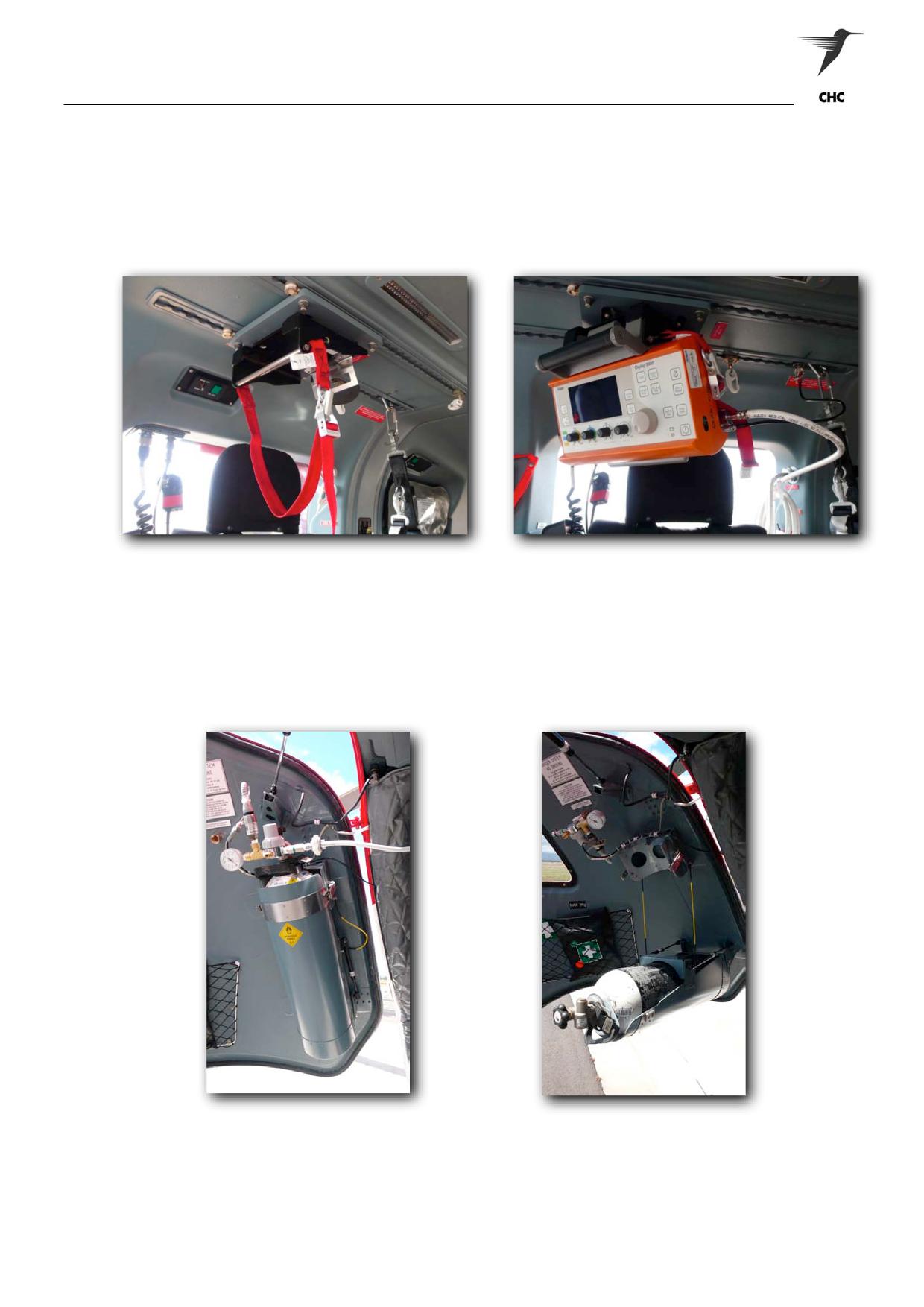
Aircraft Description
Oxylog Installation
The Oxylog 3000 and associated equipment are not stowed on the aircraft permanently. The unit will be
carried on a job-by-job basis, at the medical crew judgment. The Oxylog 3000 can be used for many
applications however; the Oxylog should not mounted prior to winching operations or personnel occupying
the side facing fold-down seat as it will hinder cabin staff’s activities.
Figure 1-39 Oxylog 3000 Mounting Bracket
Figure 1-40 Oxylog 3000 Mounted
Medical Oxygen Stowage
One ‘D’ size medical oxygen cylinder is located on the internal LH clam shell door, where the cylinder can
be accessed from the rear cabin. Turning the cylinders on is achieved by turning the handle anti clockwise
direction slowly. Cylinder contents will be displayed on the regulator gauge, and also on the oxygen
monitor (Fig 1-32). The Aircrewman or Aircraft Captain will conduct the replacement of the cylinder.
Figure 1-41 Medical Oxygen Storage
Figure 1-42 Cylinder Mount Extended
WARNING:
IN THE EVENT OF A CABIN FIRE OR EMERGENCY LANDING THE CREW ARE TO
ENSURE THAT ALL OXYGEN VALVES CLOSED; INCLUDING THE MAIN CYLINDER.
ASNSW EC145 Cabin Staff Training Notes
Revision 1 - July 2010
page 26 of 34
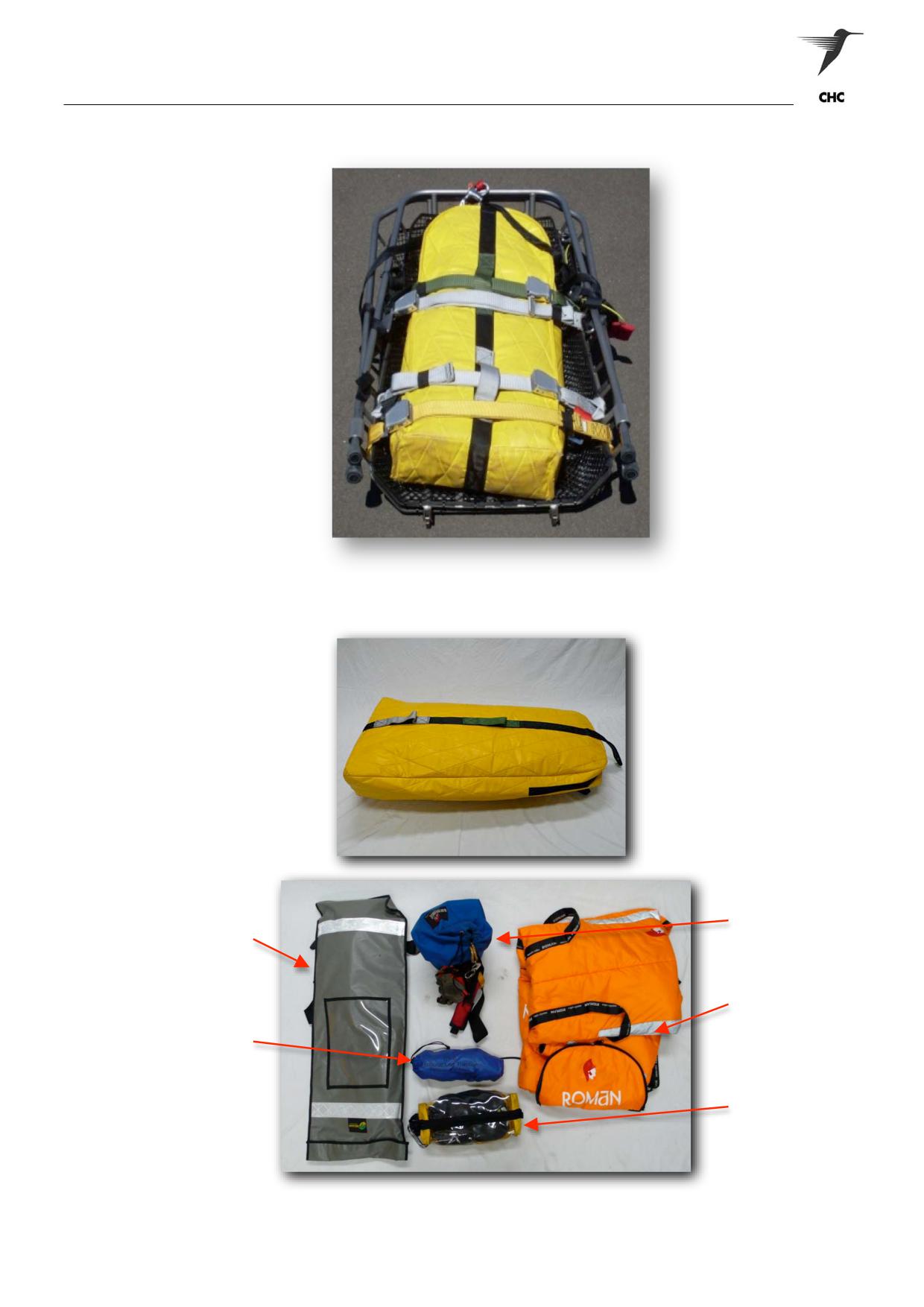
Aircraft Description
Medevac II Rescue Stretcher
Figure 1-43 Medevac II Rescue Stretcher (split)
Winch Equipment Bag& Contents
Tagline Kit
Kendrick
Extraction Device
Thermal Capsule
Femur Splint
Patient PPE Kit
Figure 1-44 Winch Equipment Bag & Contents
ASNSW EC145 Cabin Staff Training Notes
Revision 1 - July 2010
page 27 of 34
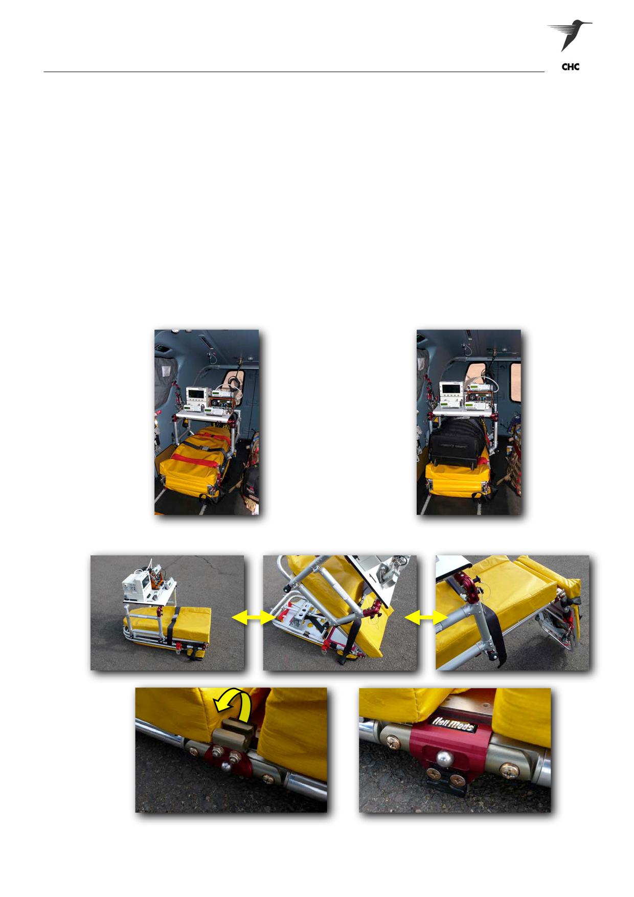
Aircraft Description
Stretcher Systems
General
The EC145 is fitted with a HeliMods Stretcher (HeliMods F12), which incorporates a functional stretcher
locking system. The HeliMods F12 is a foldable stretcher that incorporates six swivel caster wheels fitted to
the underside, plus a built-in multi adjustable backrest for the patient’s comfort. The stretcher is rated up to
a maximum load of 160 kg, although the ASNSW applies a safe working limit 130kg - patient weight.
WARNING:
FOR ALL TAKE-OFFS AND LANDINGS THE STRETCHER’S BACKREST MUST IN
THE FULL HORIZONTAL POSITION, UNLESS THE MEDICAL CREW DEEMS THAT
PATIENT’S HEALTH MAYBE COMPROMISED.
Stowage / Assembly
When the HeliMods F12 is not in use the stretcher can be folded and secured to the floor, with the bridge
fitted (Fig 1-46). When the stretcher is required for patient use, it can simply be assembled with the bridge
fitted; preferable having the bridge initially fitted in correct orientation (Fig 1-48).
Figure 1-46 Secured to Cabin Floor
Figure 1-47 Secured with Inter-Hospital Pack
Figure 1-48 Assembling the Stretcher for Use
ASNSW EC145 Cabin Staff Training Notes
Revision 1 - July 2010
page 28 of 34