Carrier 30AWH004HB / 30AWH006HB / 30AWH008HB / 30AWH012HB. Service Manual - page 7
97
30AW
Carrier
interfaces
7
108
ALARM-DEFROST OR
HUMIDITY
SELECTION
This code is use to select the output connected at PIN 11 on
terminal strip:
1. Unit alarms and/or Defrost
2. Humidity Control
1
2
2
109
FROST DELTA
SET-POINT
This code is use to set the frost delta set-point used by the Anti
frost protection logic as per algorithm.
0°C
6°C
1°C
110
RESET COMPRESSOR
RUN-TIME
This code is use to reset the compressor timer to zero.
No
yes
No
111
(
)
FLOW SWITCH STATUS
This code displayes the Flow Switch status:
0. Water not flowing
1. Water flowing
-
-
-
112
HEAT CLIMATIC
CURVE NUMBER
This code is use to select the heat climatic curve number:
0. No predefined climatic curve (Installer has to draw CC)
1 - 12. Refers to NUI manuals for climatic curve details.
0
12
0
113
HEAT WATER
SET-POINT
This code is use to set the fixed heating water set-point.
20°C
60°C
45°C
114
ECO HEAT
TEMPERATURE
REDUCTION
This code is use to set the temperature reduction value for fixed
heating water set-point when the unit is in ECO mode.
1°C
20°C
5°C
115
COOL WATER
SET-POINT
This code is use to set the fixed cooling water set-point.
4°C
25°C
7°C
116
ECO COOL
TEMPERATURE
REDUCTION
This code is use to set the temperature reduction value for fixed
cooling water set-point when the unit is in ECO mode.
1°C
10°C
5°C
117
COOL CLIMATIC
NUMBER
This code is use to select the cool climatic curve number:
0. No predefined climatic curve (Installer has to draw CC)
1 - 2. Refers to NUI manuals for climatic curve details
0
2
0
118
MIN OUTDOOR
AIR TEMPERATURE
HEATING
This code is use to select the minimum outdoor temperature of
the heating climatic curve, depending on the country where the
system is installed.
-20°C
+10°C
-7°C
119
MAX OUTDOOR
AIR TEMPERATURE
HEATING
This code is use to select the maximum outdoor temperature of
the heating climatic curve.
10°C
30°C
20°C
120
MIN WATER TEMPERA-
TURE HEATING
This code is use to select the minimum water temperature of the
heating climatic curve.
20°C
60°C
40°C
121
MAX WATER TEMPERA-
TURE HEATING
This code is use to select the maximum water temperature of the
heating climatic curve.
20°C
60°C
55°C
122
MAX OUTDOOR
AIR TEMPERATURE
COOLING
This code is use to select the maximum outdoor temperature of
the cooling climatic curve, depending on the country where the
system is installed.
24°C
46°c
40°C
123
MIN OUTDOOR AIR
TEMPERATURE CO-
OLING
This code is use to select the minimum outdoor temperature of
the cooling climatic curve
0°C
30°C
22°C
124
MIN WATER TEMPERA-
TURE COOLING
This code is use to select the minimum water temperature of the
cooling climatic curve.
4°C
20°C
4°C
125
MAX WATER TEMPERA-
TURE COOLING
This code is use to select the maximum water temperature of the
cooling climatic curve.
4°C
20°C
12°C
126
GMC OAT THERMISTOR
This code is use to define if GMC OAT thermistor is installed or n
ot:
1. GMC thermistor installed
2. GMC thermistor not installed
1
2
2
127
(
)
TO SENSOR VALUE
This code displayes the outdoor air temperature value read by
the TO sensor.
-
-
-
128
(
)
TE SENSOR VALUE
This code displayes the refrigerant temperature value read by the
TE sensor.
-
-
-
129
(
)
TS SENSOR VALUE
This code displayes the suction temperature value read by the
TS sensor.
-
-
-
130
(
)
TD SENSOR VALUE
This code displayes the discharge temperature value read by the
TD sensor.
-
-
-
131
(
)
CDU MODE
This code displayes the actual Heat Pump operating mode:
0ò
2. Cool
3. Heat
4. Fail
5. Defrost
-
-
-
132
(
)
MAX COMPRESSOR
FREQUENCY
This code displayes the maximum compressor frequency calcula-
ted by GMC control board.
-
-
-
133
(
)
REQUESTED
FREQUENCY
This code displays the requested frequency by the system
control.
-
-
-
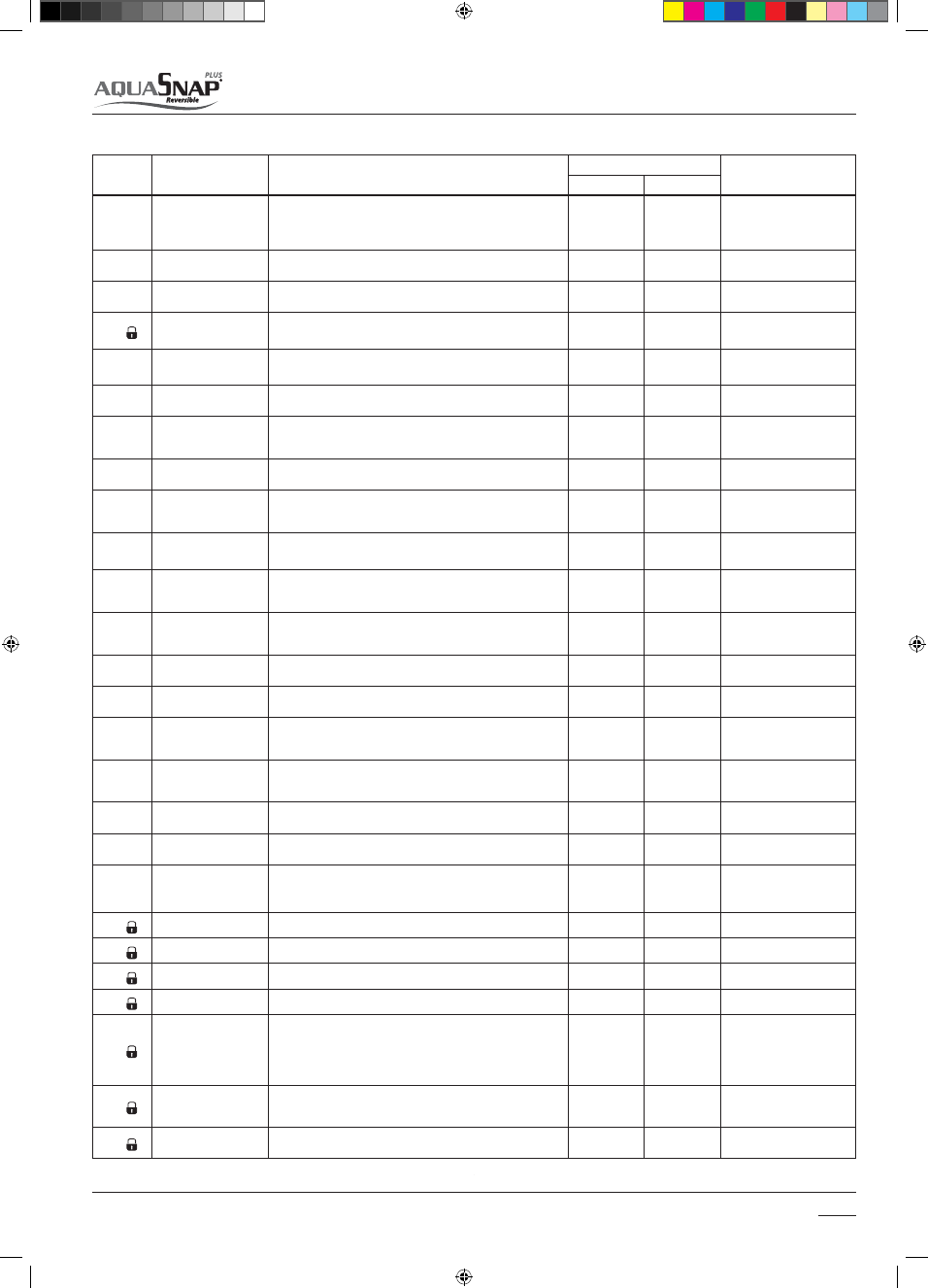
Code Nr.
Name
DESCRIPTION
VALUE RANGE
STANDARD
Min
Max
14-03-2011 14:46:20