Rolls-Royce Engine 250–C18, 250–C18A, 250–C18B, 250–C18C. Operation and Maintenance Manual (2003) - page 12

Installing Torquemeter Shaft Support
FIG. 108
E. Assemble the power and accessories gearbox cover to the housing as follows:
(1) Apply a thin film of sealing compound (Scot Clad 776 or equivalent) to the gearbox housing
splitline.
NOTE: A strand of dental floss (or equivalent), gently pressed into the Permatex around the
splitline, will give added assurance against oil leaks.
(2) Install the 6886201 power takeoff roller bearing guide in the helical power takeoff gearshaft.
(Ref. FIG. 109) Install 6796941 seal guide, detail -14 in the tachometer and governor power
train spur gearshaft.
(Ref. FIG. 110) Install 6895957 alignment tool over the oil tubes at the oil
pump.
(3) With the gearbox housing mounted in 6795579 stand and in a horizontal position, carefully
assemble the gearbox cover to the gearbox housing, aligning the oil transfer tubes, the
scavenge oil pickup tube, and the fuel control and oil pump flex shaft coupling. Insert 6799790
adapter in the tachometer and governor power train spur gearshaft. This may be used to turn
the gear train to assist in assembly. Rotate the fuel control and oil pump spur idler gearshaft
by hand to assure proper engagement with the fuel control spur gearshaft. Remove 6895957
alignment tool.
Page 258

Seal Guide Location (Cover)
FIG. 109
Seal Guide Location (Housing)
FIG. 110
Page 259
(4) Apply antiseize compound lightly to the threads of studs and bolts used to attach the gearbox
cover to the gearbox housing. The cover is secured by 39 nuts, 4 bolts, and 43 washers.
Install hardware as follows: (Ref. FIG. 83, Sheet 1 of 2.)
(a) Torque the two 10-32 bolts to 20-25 lb in. (2.3-2.8 N.m).
(b) Torque the 10-32 nuts to 35-40 lb in. (3.9-4.5 N.m).
(c) Torque the 1/4-28 nuts to 70-85 lb in. (7.9-9.6 N.m).
(d) Torque the 5/16-24 bolt to 120-150 lb in. (14-17 N.m) and secure with lockwire.
(5) Check the operation of the power and control gear trains to ensure no binding is present
between the meshing teeth as follows:
(a) Turn the power train counterclockwise through the power turbine fuel governor pad. (Ref.
FIG. 106) Use 6799790 adapter. No binding is acceptable.
(b) Turn the control gear train counterclockwise through the gas producer fuel control pad.
(Ref. FIG. 106) Use 6799790 adapter. No binding is acceptable.
(6) Remove the 6886201 power takeoff roller bearing guide from the helical power takeoff
gearshaft. Install the gearbox housing seal in the power output pad (use detail -19). Lubricate
the seal with engine oil prior to installation.
125. Engine Check Run Operating Instructions
A. Check run the engine in the airframe when the compressor assembly, compressor case, turbine
assembly, combustion section, gearbox, fuel control, governor, fuel pump, fuel nozzle, or
thermocouple has been removed, repaired or replaced. Operate the engine in accordance with
Engine Operating Procedures, Section II. Make note of all incidents of the run such as leaks,
abnormal vibration or noises, and/or any irregular functioning of engine equipment. Also note that
the following items are within limits:
(Refer to Operating Limits, Section 2, para 3.)
(1) Measured gas temperature. (Section II Table I.).
(2) Output shaft torque. (Section II Table II.)
(3) Oil pressure.
(Refer to Oil Pressure and Temperature, Section II.)
(4) Gas producer N1 speed. (Refer to Engine Speed, Section II.)
(5) Power turbine N2 speed. (Refer to Engine Speed, Section II.)
126. Diffuser Vent Orifice Selection/Installation
A. Select and install the diffuser vent orifice as follows:
(1) Install a -7 size orifice on the diffuser vent tube.
(Ref. FIG. 111)
(2) Clean the area around the orifice.
CAUTION: DO NOT INSTALL A SMALLER ORIFICE (LOWER DASH NUMBER) THAN THAT
REQUIRED TO STOP SPEWING OR SMOKING AT THE VENT.
(3) Following the next flight of at least five minutes duration, inspect the area around the orifice. If
there is any evidence of smoking or spewing from the vent, reduce the orifice size by installing
the next lower dash number orifice.
(4) Repeat the flight, inspection, and orifice replacement until no evidence of spewing or smoking
is encountered.
(5) As an alternate method for obtaining the desired orifice size, start with two -2 size orifices (No.
1 and No. 2).
Page 260

Diffuser Vent Orifice-Coupling Nut Secured
FIG. 111
(a) Drill out No. 1 orifice to 0.236-0.244 in. (5.994-6.198 mm). No. 1 orifice then becomes a
-3 orifice. If No. 1 does not smoke when checked during engine operation, resize No. 2
orifice.
NOTE: When smoking is encountered, reinstall the previously drilled smaller orifice that
did not smoke.
(b) Drill out the No. 2 orifice to 0.266-0.274 in. (6.756-6.960 mm). No. 2 orifice then
becomes a -4 orifice. If No. 2 does not smoke when checked during engine operation,
resize No. 1 orifice.
(c) Drill out the No. 1 orifice to 0.296-0.304 in. (7.518-7.722 mm). No. 1 orifice then
becomes a -5 orifice. If No. 1 does not smoke when checked during engine operation,
continue alternately enlarging the No. 1 then the No. 2 orifice by one dash number size
until the desired orifice is obtained.
(6) Record the size of the finally selected orifice (by dash number) in the Engine Log.
Page 261
127. Engine Check Run Schedule
A. Check run the engine in the airframe in accordance with the following schedule:
Engine Check Run
Setting No.
Condition
1.
Start engine and accelerate to Ground Idle. N1 = 59-65%
Observe engine for abnormal conditions such as vibration, noise or leakage.
Duration of run need not exceed five (5) minutes.
2.
Accelerate to a power setting just short of lift off. Stabilize for five (5) minutes.
3.
Reduce speed to Ground Idle. Check operation of anti-ice valve. Dwell for
two (2) minutes.
4.
Shut down the engine.
NOTE: Give the engine a thorough visual inspection after shutdown. Repeat the check run if any
repairs are necessary as a result of the run or the inspection.
128. Vibration Test Procedure
A.
Description Of Vibration Test Procedure
(1)
The procedures in this paragraph will aid in evaluating vibration, identifying vibration sources
and analyzing vibration levels so that corrective action may be taken. Continued engine
operation with high vibration levels will cause excessive engine and component wear, and can
contribute to engine failure and premature engine removal.
(2)
Engine vibration may be influenced by factors including aircraft installation, accessories,
normal wear, maintenance practices, or unusual operating conditions. By measuring the
frequency and magnitude of a vibration, then comparing the measurements with known
vibration factors, such data may be used to obtain an indication of the engine area requiring
corrective action.
(3)
Vibration is a mechanical oscillation or motion about a reference point. Engine-induced
vibration is generally observed at frequencies equal to N1 or N2 rotor speeds, gear rotational
speed, gear mesh frequency, or bearing passage rate. In some instances, the vibration also
appears as a harmonic or multiple of the basic frequency.
(4)
Vibration pickups (transducers) are used to convert vibration motion to an electrical signal.
These pickups may be calibrated in terms of vibration displacement (“mils”), acceleration
(“g’s”), or velocity (“IPS”). Velocity is the most meaningful measure of vibration on Model 250
engines.
(5)
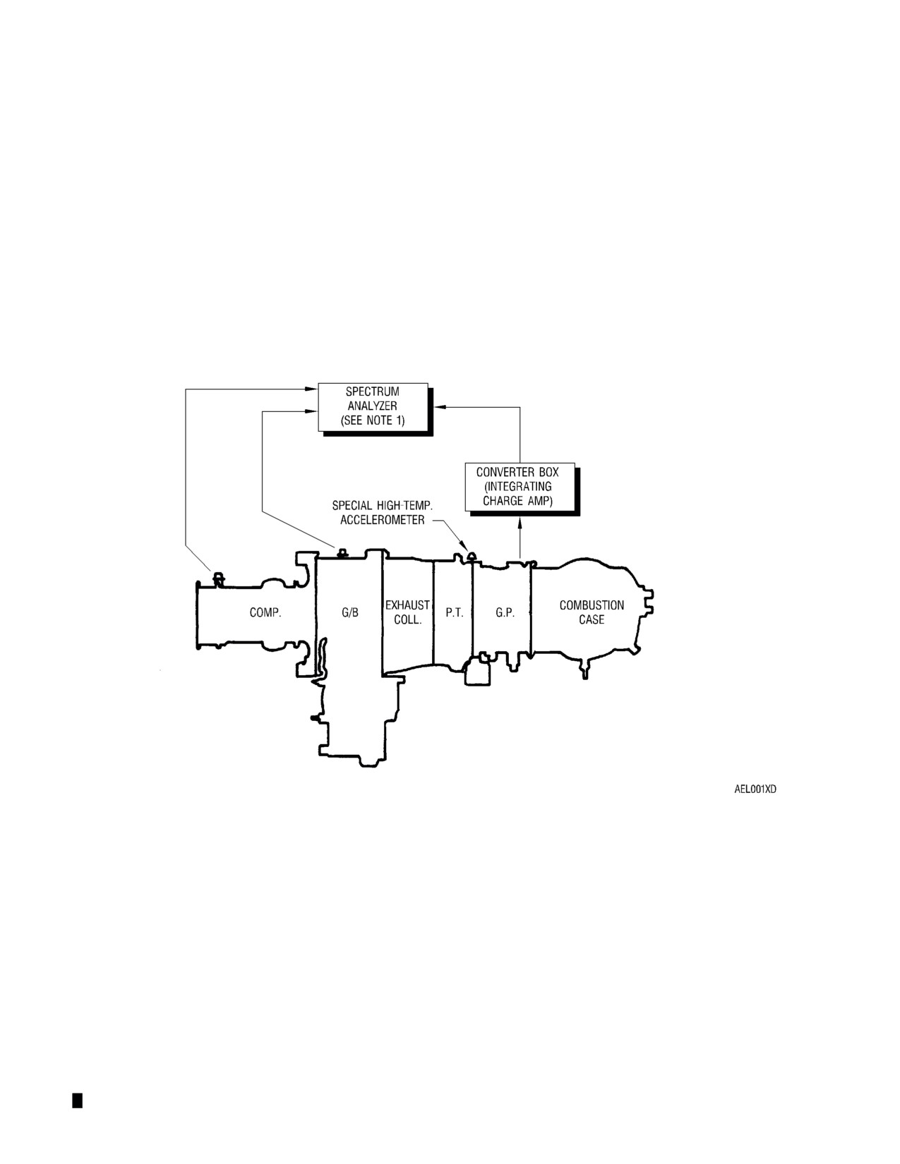
A vibration signature should be performed on each engine or aircraft using a spectrum
analyzer. The signature should be repeated at scheduled intervals, such as 100 hours, and a
file should be maintained for each engine-air-craft combination. When a major change in the
frequency response is noted, such as the level changing from 0.2 IPS to 0.6 IPS, closer
monitoring should be maintained on such engine.
(6)
Signatures should be taken with pickups installed in the vertical axis on the compressor,
gearbox and turbine. The signatures should be taken at several specified N1 speeds while the
aircraft is on the ground; these N1 speed points are to be used for each signature. An overall
vibration reading can be obtained by using the broad band control on a Chadwick Helmuth
Model 192 analyzer, which is the equipment used in the following procedures.
(7)
The test chart (see Vibration Recording Sheet, FIG. 112) contains a number of test points. A
vibration trend monitoring program can be initiated on an aircraft by using this chart to set the
baseline. The monitoring program should be maintained by using points 3, 5 and 6 on FIG.
112 at the specified intervals (100, 150, 200 hours, etc.). Any time there is a major variance in
charted readings, or whenever high vibrations are indicated, a complete vibration survey
should be made prior to initiating troubleshooting.
Page 262
B. Glossary Of Terms
(1) The following terms are included in the vibration test procedure:
Glossary of Terms
Term
Definition
ACCELERATION
Rate of change of velocity with time along a specified axis. Usually
expressed as “g’s”, or gravitational units.
AVERAGE
Peak value multiplied by 0.637
CYCLE
An interval of time during which sequence of a recurring succession
of events is completed. In the case of vibration, one complete perfor-
mance of a vibration.
DISCRETE FREQUENCY
A measure of vibration response at one frequency only.
DISPLACEMENT
Specifies change of position in mils. Usually measured from mean
position (or position of rest) and applies to linear motion, although it
can apply to angular motion.
FREQUENCY
A measure of vibration response expressed in Hertz (Hz).
HERTZ (Hz)
A measurement of the frequency of a vibration. Also, cycles per se-
cond (CPS) is sometimes used in association with frequency.
OVERALL
A vibration measurement of all frequencies as read on an average
detecting meter.
PEAK
The extreme value of a varying quantity. Measured from zero, or
mean value. Peak to peak is 2 times a peak level.
VELOCITY
Refers to rate of change of displacement with time along a specified
axis; quickness of motion. Usually measured in Inches Per Second
(IPS).
Page 263
VIBRATION RECORDING SHEET
AIRCRAFT TYPE:
DATE:
AIRCRAFT SERIAL:
TIME SINCE NEW:
ENGINE SERIAL NUMBER:
ENGINE TSN/TSO:
GEARBOX SERIAL NUMBER:
GEARBOX TSN/TSO:
COMPRESSOR SERIAL NUMBER:
COMPRESSOR TSN/TSO:
TURBINE SERIAL NUMBER:
TURBINE TSN/TSO:
IPS BROAD-
ALTITUDE
OAT
N2
N1
TORQUE
BAND
NOTES
A B
1
C D
GROUND IDLE
A B
2
85%
C D
A B
*3
100%
C D
FLAT PITCH
A B
4
100%
87%
C D
A B
*5
100%
95%
C D
A B
*6
100%
95%
C D
USE GREEN CARD
A B
7
100%
C D
**SEE NOTE 1
A B
8
100%
C D
***SEE NOTE 2
USED FOR ENGINE MONITORING PROGRAM
** NOTE
1.
DO NOT EXCEED ANY ENGINE/TRANSMISSION OR AIRCRAFT FLIGHT LIMITS. UTILIZE
MAXIMUM ALLOWABLE POWER AND MAINTAIN LEVEL FLIGHT.
*** NOTE 2. CLIMB 3000 FEET ABOVE THE ALTITUDE RECORDED IN CHECK #7 AND PERFORM
MAXIMUM ALLOWABLE POWER CHECK (MAINTAIN LEVEL FLIGHT).
--
USE BLUE CARDS ON ALL CHECKS UNLESS OTHERWISE NOTED.
–-
DEPRESS BROAD BAND SWITCH AT MAXIMUM RPM AND RECORD READING.
–-
USE 10 IPS SIDE OF RECORDING CHART.
–-
USE THREE PICKUPS ON THE NORMAL ENGINE VIBRATION PICKUP POINTS.
–-
ALL THREE PICKUP POINTS CAN BE ON ONE CARD PROVIDING DIFFERENT COLORED
PINS ARE USED AND THEY ARE APPROPRIATELY MARKED.
Vibration Recording Sheet
FIG. 112
Page 264
C.
Vibration Test Equipment Requirements
(1) Equipment consists of transducers (pickups), brackets, attachment hardware, cables and a
spectrum (frequency) analyzer with plotter. The equipment must function as an integrated
system capable of vibration measurement over a minimum range of 15 to 1500 Hz (900 to
90,000 rpm); higher ranges are desireable. The system must be capable of measuring
vibration levels from at least 0.050 to 5 IPS average velocity. Currently acceptable equipment
is listed below.
(a) Acceptable Equipment:
1
Chadwick-Helmuth Model 192, 192A, and 8500 Analyzer/Plotter and Model 7570
High Temperature Accelerometer Kits
2
Rotortuner by MCT Helitune
3
Scientific Atlanta Model 2538
4
Helitune Quan-Tech 9500 Spectrum Analyzer
(b) Other equivalent units may also be utilized.
D.
Vibration Test Procedure
CAUTION: PERFORMANCE OF THIS PROCEDURE REQUIRES KNOWLEDGE OF BOTH
ENGINE AND AIRCRAFT MAINTENANCE PROCEDURES. REFER TO THE
RESPECTIVE OPERATION AND MAINTENANCE MANUALS.
CAUTION: SECURE PICKUP LEAD WIRES TO PREVENT ENTANGLEMENT WITH
AIRCRAFT CONTROL LINKAGES. ROUTE LEAD WIRES TO PREVENT
SURFACE CONTACT WITH ENGINE.
NOTE: The following procedures apply to use of the Chadwick Model 192 analyzer.
Operational procedures for other analyzers will be similar.
(1) Install vibration pickups vertically on each engine module as shown in FIG. 113 and in the
following instructions.
(a) Compressor. Install one vertical vibration pickup on the front side of the
compressor-to-inlet housing splitline at the 12 o’clock position. Use a balance “T”-type
bracket, such as Rolls-Royce part number 23032992 (Ref. FIG. 114).
(b) Power and Accessory Gearbox. Install one vertical vibration pickup on the power and
accessory gearbox top mounting pad. Refer to FIG. 115 for fabrication of this mount, if
required.
CAUTION: THE TURBINE PICKUP MUST BE A HIGH TEMPERATURE PICKUP IN
ORDER TO WITHSTAND THE EXTREME HEAT OF THE TURBINE CASE.
(c) Turbine. Install one vertical vibration pickup on the forward side of the gas
producer-to-power turbine support splitline at the 12 o’clock position. Use a balance
“T”-type bracket such as Rolls-Royce part number 23032992 (Ref. FIG. 114) or use the
equipment manufacturer’s bracket.
Page 265
Vibration Pickups Installation
FIG. 113
Page 266

Accelerometer Mounting Bracket P/N 23032992
FIG. 114
Page 267

Accessory Gearbox Mounting Pad P/N 23032993 Manufacture
FIG. 115
Page 268
NOTE: Be sure that the spectrum analyzer and vibration pickups are properly calibrated.
Refer to manufacturer calibration equipment and procedures. It is recommended
that pickups be calibrated before each use or whenever out-of-normal vibration
levels are detected, with minimum calibration time every six months.
(2) Using the blue card (10 IPS side) in the spectrum analyzer, measure the frequency range
desired at any test point except test point 6 (Ref. FIG. 116).
(3) Using the green-border card (10 IPS side) in the spectrum analyzer, measure the frequency
range desired at test point 6 (Ref. FIG. 117).
(4) Secure cowlings as required by aircraft flight manual for safe ground and flight operation.
CAUTION: ENSURE THAT ENGINE AND TRANSMISSION LIMITS ARE NOT EXCEEDED ON THE
GROUND OR IN FLIGHT DURING THE TEST SEQUENCE. REFER TO APPLICABLE
ENGINE/AIRFRAME MANUALS.
(5) Start engine to idle. Operate engine as necessary to bring oil system to normal operating
temperature range.
(6) Record data indicated below:
(a) Ground Operation:
1
Record applicable vibration data (Ref. FIG. 112). Record as many test points as
possible before flying.
CAUTION: PRIOR TO OPERATION IN FLIGHT, BE SURE THAT ALL EQUIPMENT AND
CABLES ARE SECURED AND DO NOT INTERFERE WITH THE OPERATION
OF THE ENGINE OR AIRCRAFT FLIGHT CONTROL SYSTEM.
(b) Flight Operation:
1
Fly the aircraft and record the remaining test points.
NOTE: Current average limits for discrete frequencies are 1.0 IPS, with an overall
average of 1.5 IPS.
(7) Determine if maintenance action is indicated by comparing the newly acquired data with
previously recorded data and with maximum allowable limits (Ref. FIG. 118).
Page 269

Typical Chadwick Vibration Analysis Card 5,000 to 60,000 rpm
FIG. 116
Page 270

Typical Chadwick Vibration Analysis Card 10,000 to 900,000 rpm
FIG. 117
Page 271
E.
Interpretation Of Vibration Data
(1)
The first step is to determine if the vibration is airframe or engine related. Any rotational speed
below 6000 rpm (100 Hz) is usually airframe related, because the slowest rotational speed of
the engine is the power output shaft at 6000 rpm (except for some accessory drives and the
propeller reduction gearbox shaft).
(2)
Typical engine vibration signature cards are shown in FIG. 116 and 117. These curves
represent the peak vibration velocity for frequencies between 5,000 and 900,000 rpm.
Analysis of this signature is accomplished as follows:
(a) Determine the vibration frequencies (rpm) and vibration velocity amplitude (IPS peak) of
the major vibration peaks on the plot cards. Then convert these values to inches per
second (IPS) average velocity using the following conversion factors:
1
IPS Peak multiplied by 0.637 = IPS Average Velocity
2
RPM divided by 60 = Hertz (cycles per second)
3
Gear rpm multiplied by the number of gear teeth = gear mesh frequency
NOTE: The vibration card used in the following example is for the frequency range
5,000 to 60,000 rpm only. The vibration level of the engine should be
checked over the entire required range of frequencies (5,000 to 900,000
rpm).
(b) Example (Normal Vibration Range). The upper end of the normal vibration range for one
discrete vibration frequency is 1.0 IPS (Average). Therefore, the engine in the following
example is well within Rolls-Royce normal vibration range (normal vibration range is
specified in FIG. 118).
Frequency
Frequency
Velocity
Velocity
RPM
Hz
IPS (Avg.)
IPS (Peak)
11,300
188
0.15
0.10
33,000
550
0.19
0.121
48,000
800
0.50
0.319
(c) Normal Operating Range. Compare IPS average velocities shown below to the normal
operating range shown in FIG. 119. In this case, the vibration is within normal operating
range.
Measured
Measured
Maximum Allowable
Frequency
Velocity
Vibration Limits
188 Hz
0.10 IPS (Avg.)
1.0 IPS (Avg.)
550 Hz
0.121 IPS (Avg.)
1.0 IPS (Avg.)
800 Hz
0.319 IPS (Avg.)
1.0 IPS (Avg.)
(d) Sources of Engine Vibration. If vibration is not within normal operating limits, the source
of vibration should be identified. Many possible sources of vibration exist, but the highest
engine-related vibration levels normally occur at rotational speeds of the major engine
components which are as follows:
Page 272

Installed Engine Vibration Limits Normal Operation Range and Limits
FIG. 118
Page 273
1
N1 Gas producer rotational speed
2
N2 Power turbine rotational speed
3
Starter generator rotational speed
4
Output shaft rotational speed
5
Rotational speeds of special engine-powered accessories
(e)
Sources of Airframe Vibration. The most frequent sources of airframe vibration are as
follows:
1
Main rotor rotational speed
2
Main rotor blade passage speed (and multiples of this speed)
3
Tail rotor drive shaft speed
4
Tail rotor rotational speed
5
Tail rotor blade passage speed (and multiples of this speed)
(f)
Identifying Engine-Related Vibrations.
1
To identify engine-related vibrations, N1 and N2 rotational speeds should be
determined first. Referring to FIG. 116, N1 was recorded as 94%, and N2 was
recorded as 100%. These speeds may be determined by analyzing the vibration
signature.
2
For example, to find N1, look for a major peak in the measured frequency range
between 510-850 Hz; this corresponds to 30,600-51,000 rpm, or 60%-100% N1.
Refer to the major peak occurring at 800 Hz (48,000 rpm) in FIG. 116. By
interpolating from the known 100% factor 850 Hz = 51,000 rpm,
3
it can be determined that 800 Hz = 48,000 rpm, or 94.1% N1, which confirms the
recorded N1 speed of 94%.
4
Similarly, N2 can be found as a major peak between 330-550 Hz; this corresponds to
19,800-33,000 rpm, or 60-100% N2. Refer to the major peak occurring at 550 Hz in
FIG. 116. The peak at 550 Hz = 33,000 rpm (which is the 100% factor), confirming
the recorded N2 speed of 100%.
5
The remaining major peaks can be identified by using speed charts to help determine
potential vibration sources. These charts list gear ratios and rotating shaft speeds
for engine-driven components. Matching the vibration peak frequency (rpm) with a
speed on the chart will indicate the most likely source for that vibration.
(g)
Speed Chart Calculations.
1
Shaft speeds on the speed charts were computed using 100% N1 and N2. If
measured N1 and N2 are not at 100%, the vibration peak frequency (speed) at which
the vibration would occur if N1 and N2 were 100% must be determined. The
resulting speed is matched to a shaft speed in the chart.
2
For example, the remaining major peak in FIG. 116 occurs at 11,300 rpm. The
notation on FIG. 116 chart indicates N1 = 94% and N2 = 100%. Since N1 is not
100%, the equivalent rpm for 100% N1 must be found:
11,300 rpm
= 12,021 rpm
0.94 N1
3
Therefore, the 100% N1 equivalent of 94% N1 at 11,300 rpm is 12,021 rpm. It is not
necessary to convert N2, since N2 is at 100%. However, both speeds (N1 and N2)
are needed for charts since it is not known if the vibration is from the N1 or N2 gear
trains.
Page 274
4
Examination of the speed chart (FIG. 119) shows the starter-generator drive
gearshaft speed of 12,034 rpm in the N1 gas producer and power turbine gear trains,
which is close to the 12,021 calculated vibration frequency. This result indicates a
vibration problem in the area of the starter-generator drive gearshaft.
5
Rule out the possibility that the vibration is from N2 by comparing the 11,300 rpm
100% N2 vibration with the speed chart (FIG. 119). No shaft speeds are close to the
11,300 rpm peak on FIG. 116.
6
The actual starter-generator spare drive gearshaft speed at 94% N1 (0.94 x 12,034)
is 11,312 rpm, and this gearshaft has caused the 11,300 rpm vibration frequency
peak in FIG. 116.
Page 275

Schematic - Gas Producer and Power Turbine Gear Trains
FIG. 119
Page 276
129. Vibration Limits
A. Limits on Separate, Individual Vibrations. The discrete frequency guidelines apply to measurement
of a particular frequency, such as 48,000 rpm (800 Hz). If tests reveal vibrations above the normal
operating range (FIG. 118), or above 1.0 IPS average velocity, action should be taken to determine
the source of the vibration and perform corrective action.
B. Overall Vibration Limits. The overall vibration guidelines apply when test equipment reads all
vibration contributions over a broad band, such as 15 to 2,000 Hz. If overall limits are exceeded,
analysis of each vibration must be made.
130. Vibration Maintenance Action
A.
There are many potential causes of vibration. Suggested areas for possible corrective action are:
(1)
N1 Frequency Vibration
(a)
Check cables, spectrum analyzer and pickups to ensure that all test components are in
proper working order and are calibrated properly.
(b)
Inspect for foreign object damage.
(c)
Check compressor and turbine attaching hardware. Retorque per applicable Operation
and Maintenance Manual instructions.
(d)
Inspect for mainshaft bearing failure or impending failure. Such failure should generate
metal particles and enable the chip indicator light. Check oil filter and magnetic chip
detectors for evidence of metal contamination.
(e)
Check for sources of N1 engine internal vibration such as:
1
No. 1 bearing
2
Compressor or impeller imbalance
3
No. 2 bearing
4
N1 system rubs including:
a Axial stages to plastic coating
b Impeller to shrouds
c Labyrinth seal knives
5
Foreign Object Damage (FOD) to compressor (usually vibration with noise)
6
No. 1 seal
7
Alignment:
a Front support
b Compressor to gearbox
8
Spur adapter gearshaft
9
Loose turbine assembly tie bolt
10
No. 8 bearing
11
No. 7 bearing
12
N1 turbine-to-compressor coupling shaft indexing
13
Gas turbine rotor
(2)
N2
Frequency Vibration. Check for sources of N2 vibration frequency such as:
(a) Turbine balance
(b) Loose power turbine inner or outer nuts
Page 277
(c) Improper gearbox-to-turbine shims
(d) No. 3, 4, 5, or 6 bearings
(3)
Output Shaft Frequency Vibration. Check output shaft frequency vibration:
(a) Check output shaft flex couplings and shaft balance
(b) Check alignment of engine to aircraft
(c) Check power takeoff gear
(d) Check freewheeling unit (if installed)
(4)
Power and Accessory Gearbox. Check high gearbox vibrations:
(a)
(Loose compressor studs
(b) No. 2-1/2 bearings
(c) No. 3 and 4 bearings
(d) Alignmemt:
1
Pinion gear
2
Case or cover
(5)
Main Rotor Vibration. Check main rotor blade passage vibration:
(a) Vibration may be in main rotor rpm times number of blades, main rotor rpm, or multiples
of these. Align, balance and track main rotor. Refer to appropriate airframe manual for
procedures.
(b) Check engine to airframe mounts. Inspect and retorque per aircraft manual instructions
(c) Check main rotor transmission mounts for condition and security per airframe manual
instructions.
(6)
Starter-Generator Vibration. Check starter generator frequency vibration:
(a) Replace unit
131. Manufacturer Assistance
If suspected airframe and engine components have been inspected, repaired, or replaced per the
appropriate manufacturer’s instructions as indicated by this vibration test data, and vibration symptoms
still persist, contact Rolls-Royce for further assistance.
132. Engine Preparation For Storage And Shipment
Engines that have been repaired and check run and will not be installed in an aircraft or engines going to
overhaul are to be prepared for storage and/or shipment in accordance with the following paragraphs.
Engines placed in storage must be inspected every 12 months. (Refer to Engine Container Preservation
Surveillance.)
133. Engine Preservation
A. Preserve the engine as follows:
(1) Drain the oil from the power and accessory gearbox by removing the bottom drain plug. Clean
and replace the plug after the oil has been drained.
(2) Preserve the compressor in accordance with Compressor Preservation.
(3) If the engine is to be stored for less than 45 days no further preservation is required.
(4) If the storage period will exceed 45 days, or the engine is being prepared for shipment,
continue with the preservation as follows:
(a) Preserve the oil system in accordance with Oil System Preservation.
Page 278
(b) Preserve the fuel system in accordance with Fuel System Preservation.
(c) Install covers on the compressor inlet and the exhaust collector stacks.
(d) Store the container indoors.
134. Engine Preparation For Shipment
A. Prepare the preserved engine for shipment as follows:
(1) Coat accessory drives which do not have accessories installed on them with engine oil. Brush
internal splines with antiseize compound (Lubriplate 130A, or equivalent) and assemble
shipping covers, gaskets, washers and nuts.
(2) Touch up paint film where damaged. Do not expose touch up areas to engine fluids or
cleaning solvents for a minimum period of 72 hours after application.
(3) All shipping parts, except accessory drive pad covers and related parts attached to the engine,
shall be identified by a light yellow color. The color may be paint or any other acceptable
process which is non-corrosive, permanent and not subject to deterioration by engine fluids
and solvents.
(4) Letters and numbers of stenciled markings shall be block letters 3/4-in. (19 mm) high
minimum.
(5) Tighten aluminum and plastic shipping caps and plugs finger tight.
(6) Torque threaded parts to standard torques.
CAUTION: REMOVE ALL SHIPPING CLOSURES PRIOR TO ENGINE OPERATION EXCEPT
COVERS ON THOSE ACCESSORY DRIVE PADS WHICH ARE NOT USED FOR
ATTACHMENT OF AIRCRAFT ACCESSORIES.
135. Engine Installation In Container
A. To install the engine in the shipping container proceed as follows:
(1) Suspend the engine from a hoist using lift 6796963.
CAUTION: USE AT LEAST ONE AND AS MANY ADDITIONAL WASHERS AS REQUIRED
UNDER THE BOLT HEAD TO PREVENT DAMAGING THE GEARBOX WITH THE
THREADED END OF THE BOLT.
B. Assemble the bottom and two side mounting pad supports on the engine. Tighten bolts until
supports are located firmly.
CAUTION: AVOID SHARP BENDS WHEN COILING THE THERMOCOUPLE LEAD.
C. On applicable engine models, coil the thermocouple lead and secure it to the top of the turbine with
one-inch (25 mm) masking tape.
D. For storage periods less than 90 days it is not necessary to position the engine in the protective bag
before placing the engine in the container assembly. For short term storage proceed as follows:
(1) Hoist the engine into the container. The top half of the laminated siding must be removed to
allow the right and left hand supports to fit into their respective retaining slots.
(2) When the engine is properly positioned in the container, remove the engine lift 6796963.
(3) Install the top half of the laminated siding.
(4) Position cover on the container.
E. For storage periods over 90 days and for overseas shipment the engine shall be sealed in the
protective bag inside the container. For this installation, proceed as follows:
(1) Install the laminated siding inside the protective bag with excessive bag material neatly folded
over and secured with one-inch (25 mm) masking tape.
(2) Cut a one-inch (25 mm) diameter hole and install valve in the bag at a point five inches (127
mm) from the right side and ten inches (254 mm) from the rear of the container. Tighten valve
nut until gasket inside bag is slightly compressed.
Page 279
CAUTION: USE CARE TO PREVENT RUPTURING THE PROTECTIVE BAG WHEN
LOWERING THE BAG AND LAMINATED SIDING ASSEMBLY INTO THE
CONTAINER.
(3) Hoist the engine into the bag and container.
(4) Position two 16-unit bags of desiccant inside the bag at each corner at the bottom of the bag.
(5) Heat seal the bag.
(6) Use an air exhaust gun to remove air from the bag until the bag clings closely to the laminated
siding.
(7) Neatly fold excessive bag material at the top of the engine. Be careful not to cover the valve.
(8) Install cover on the container.
F.
Place engine records, one copy of Engineering Design Specification (EDS) No. 1276, and
applicable records in the records envelope. Place envelop in the records receptacle of the
container. Seal receptacle with two-in. (51 mm) waterproof tape (PPP-T-76).
G.
Install eight corner protectors and two steel straps. Tighten straps until indentations are evident at
the corners of the container.
H.
Stencil the container as required.
(1)
Install the engine in the drum-type shipping container (P/N 6870176) as follows:
(a) Prepare the container for the installation.
1
Depress and hold the relief valve manual release button until the air pressure inside
the container is zero.
2
Remove the drum front head by removing the nut, bolt, and clamping band
assembly.
3
Remove the cloth bag containing bracket mounting hardware.
4
Remove the two nuts, lockwashers, and bolts retaining the engine suspension frame
assembly to the side rail assembly. Slide the frame from the drum. The frame will
rest on two yokes.
5
Remove a hairpin and flat head pin from each and separate the two engine mounting
brackets from the engine mounting bracket support adapters. Remove a hairpin and
flat head pin from each then slide the two adapters outboard until they are flush with
the inside edge of the adapter support bushings.
6
Remove the bottom engine mounting bracket. (The shipping container details
include two bottom brackets. Remove the bracket which is identical to the two side
brackets. Install the remaining bracket on the storage bracket assembly.)
(b) Assemble the bottom and two side mounting brackets on the engine. Secure each with
three bolts and washers. Torque bolts to 85-110 lb in. (9.6-12.4 N.m) and lockwire in
threes.
CAUTION: AVOID SHARP BENDS WHEN COILING THE THERMOCOUPLE LEAD.
(c) On applicable engine models, coil the thermocouple lead and secure it to the top of the
turbine with one-inch (25 mm) masking tape.
(d) Lower the engine onto the engine suspension frame assembly. The bottom engine
mounting bracket must engage the female adapter bracket. Stop lowering the engine
when the side mounting brackets are aligned with the engine mounting bracket support
adapters. Secure each of the two adapters to the mounting brackets with a flat head pin
and hairpin. Secure each of the two adapters to the adapter support bushings with a flat
head pin and hairpin. Release engine weight onto the frame.
(e) Tie the empty cloth bag to the desiccant receptacle for future use.
Page 280
(f)
Lift or hoist the engine loaded frame until the side rails align with the side rail assemblies.
Slide the frame into the drum.
NOTE: If a hoist was used to lift the engine loaded frame assembly, the lift tool must be
removed from the engine top pad before the engine can slide all the way into
the drum.
(g) Secure the side rails to the side rail assemblies with a bolt, lockwasher, and nut on each
side. Torque nuts to 150-180 lb in. (17-20 N.m).
(h) Position two 16-unit bags of desiccant into the desiccant receptacle. Replace the
humidity indicator element only if necessary.
(i)
Assemble the closure gasket and the front head on the drum. Secure the head with the
clamping band. Use a special scissors-type clinch tool to hold the band so that the
retaining bolt and nut can be installed. Tighten torque nut until the head, gasket, and
band are seated firmly. Lead-seal lockwire the bolt to the bushing sleeve.
(j)
Position one copy of EDS 1311 and applicable engine records in a plastic envelope.
Store the envelope in the records receptacle. Lead-seal lockwire the cover to the
receptacle.
(k) Coat the nut end of the container closure bolt with corrosion preventive compound.
(2)
Install the engine in a rectangular-type shipping container (P/N 6873174) as follows:
(a) Prepare the container for the installation.
1
Depress and hold the relief valve manual release button until air pressure inside the
container is zero.
2
Remove the eight nuts and screws securing the cover to the base. Attach a hoist at
the lifting hooks and remove the container cover from the base.
3
Separate the two side engine mounting brackets from the engine mounting bracket
adapters by removing a hairpin and flat head pin from each.
4
Loosen the two engine mounting bracket adapters in the upper mounting adapter
support bracket by removing a hairpin and flat head pin from each. Slide the
adapters outboard until they are flush with the inside edge of the support bracket.
5
Remove the bottom engine mounting bracket. (The shipping container details
include two brackets. Remove the bracket which is identical to the two side
brackets. Install the remaining bracket at the storage location on the channel
weldment.)
(b) Assemble the bottom and two side mounting brackets on the engine. Secure each with
three bolts and washers. Torque bolts to 85-110 lb in. (9.6-12.4 N.m) and lockwire in
threes.
CAUTION: AVOID SHARP BENDS WHEN COILING THE THERMOCOUPLE LEAD.
(c) On applicable engine models, coil the thermocouple lead and secure it to the top of the
turbine with one-inch (25 mm) masking tape.
(d) Lower the engine onto the base assembly. The bottom engine mounting bracket must
engage the tube of the lower mounting bracket. Stop lowering the engine when the side
mounting brackets are aligned with the engine mounting bracket adapters. Slide the
adapters inboard to engage the engine side mounting brackets. Secure each of the two
adapters to the mounting brackets with a flat head pin and hairpin. Secure each of the
two adapters to the upper mounting adapter support bracket with a flat head pin and
hairpin. Release the engine weight onto the base. Remove the lifting hoist.
(e) Tie the empty cloth sack to the mounting frame upper tube for future use.
(f)
Position two 16-unit bags of desiccant into the desiccant receptacle. Replace the
humidity indicator element only if necessary.
Page 281
(g) Position the closure gasket then lower the cover over the engine loaded base. Align
cover to base at each end with a locating pin. Be sure the closure gasket is properly
seated.
(h) Remove the hoist from the cover. Attach the cover to the base with eight screws and
nuts (nut end up). Torque nuts to 150-165 lb in. (17-19 N.m).
(i)
Lead-seal wire the cover to the base at the two tamper-proof security holes.
(j)
Remove the records receptacle cover. Position one copy of EDS 1312 and applicable
engine records in the receptacle. Install the cover; secure with four screws, flat washers,
and rubber washers. Torque screws to 30-40 lb in. (3.4-4.5 N.m). Lead-seal lockwire
screws in pairs.
(k) Coat the nut end of the container closure bolts with corrosion preventive compound.
136. Engine Removal From Container
A.
Remove the engine from fiberboard container (P/N 6855089) as follows:
(1) Remove the two steel straps and the container cover.
(2) If the protective bag has been used, cut the bag from end to end for engine removal.
NOTE: Cut in a straight line just below the heat seal line so the bag may be reused.
(3) Hoist the engine from the container using lift 6796963.
(4) Remove the three mounting pad supports from the engine.
(5) Remove all shipping parts from the engine which are not needed to cover engine openings.
Position shipping parts in the container to be reused.
B.
Remove the engine from the drum-type shipping container (P/N 6870176) as follows:
(1) Depress and hold the relief valve manual release button until the air pressure inside the
container is zero. Remove the drum front head by removing the nut, bolt, and clamping band
assembly.
(2) Remove the cloth bag containing bracket mounting hardware.
(3) Remove the two nuts, lockwashers, and bolts retaining the engine loaded frame assembly to
the side rails. Slide the engine and frame assembly from the drum. The frame will rest on two
yokes.
CAUTION: PROVIDE ADEQUATE SUPPORT AT BOTH ENDS OF THE LOADED FRAME TO
PREVENT IT FROM FALLING TO THE FLOOR AS THE LOAD IS DISENGAGED
FROM THE SIDE RAILS. THE FRAME CAN BE SUPPORTED BY ATTACHING A
LIFT TOOL AND HOIST AT THE ENGINE TOP MOUNTING PAD WHEN THE
FRAME IS ABOUT HALF WAY OUT OF THE DRUM.
(4) Adjust the hoist to take the engine weight off of the frame assembly.
(5) Separate the two engine mounting bracket support adapters from the adapter support
bushings and from the engine mounting brackets by removing the hairpin and flat head pin at
each location. Slide the two adapters outboard until they are flush with the inside edge of the
adapter support bushings.
(6) Hoist the engine from the frame assembly.
(7) Remove the three mounting brackets from the engine.
(8) Reinstall container parts into their respective locations and position loose hardware in the cloth
bag. Tie the bag to the desiccant receptacle for future use.
(9) If the container will be exposed to corrosive conditions, coat the nut end of the closure bolt with
corrosion preventive compound.
C.
Remove the engine from a rectangular-type shipping container (P/N 6873174) as follows:
(1) Depress and hold the relief valve manual release button until the air pressure inside the
container is zero.
Page 282
(2) Remove the eight screws and nuts securing the cover to the base. Attach a hoist at the lifting
hooks and remove the container cover from the base.
(3) Attach a lift bracket and hoist to the engine top mounting pad. Adjust the hoist to take the
engine weight off of the container suspension system.
(4) Separate the two engine mounting bracket adapters from the side engine mounting brackets
and from the upper mounting adapter support brackets by removing a hairpin and flat head pin
at each location. Slide the two adapters outboard until they are flush with the inside edge of
the support brackets.
(5) Hoist the engine out of the container.
(6) Remove the engine mounting brackets from the bottom and both sides of the engine.
(7) Reinstall container parts into their respective locations and position loose hardware in the cloth
sack. Tie the cloth sack to the mounting frame upper tube for future use.
(8) If the container will be exposed to corrosive conditions, coat the nut end of the eight closure
screws with corrosion preventive compound.
137. Engine Container Reuse
All of the containers are designed to be reusable. Reuse as many of the shipping parts stored within the
container as possible.
138. Engine Container Preservation Surveillance
The shipping package must undergo humidity indicator element inspection upon receipt of the engine.
The inspection shall be repeated every 30 days.
NOTE: Fiberboard containers (P/N 6855089) and their plastic bag inserts must be opened for humidity
indicator card inspection.
A.
If the humidity indicator is light blue (white to blue is also acceptable), the moisture level in the bag
or container has been satisfactory. Make note of the humidity inspection in the Engine Log.
Satisfactory engines stored in fiberboard containers (P/N 6855089) shall be returned to storage
condition as follows:
(1) Replace the eight 16-unit bags of desiccant.
(2) Heat seal and exhaust the bag.
(3) Fold excess bag material at the top of the engine. Be careful not to cover the valve.
(4) Reinstall the container cover. Retain with two steel straps.
B.
If the humidity indicator is light lavender or pink, the moisture level in the bag or container has been
unsatisfactory. Return the engine to storage condition as follows:
(1) Remove the engine from the container and inspect for evidence of moisture. Normally the first
condition encountered will be galvanic corrosion in areas having dissimilar metals in contact
with each other such as steel bolts and fittings contacting the magnesium gearbox.
(2) If corrosion is not found, replace the humidity indicator element and return the engine to
storage. (See step a if the fiberboard container is used for storage.)
(3) If corrosion is found, clean or replace the corroded parts as necessary. Remove shipping
parts and install the engine on a test stand or in an airframe. Start the engine and accelerate
to Ground Idle. Operate at this engine power setting or above for a sufficient length of time
(approx. five minutes) to accomplish the following: depreserve the fuel system, recoat all
lubricated interior components, and thoroughly remove moisture from the engine. Upon
completion of the engine run, preserve the engine and return it to storage in the normal
manner described in this section.
(4) Replace or rejuvenate the desiccant. Replace with No. 88 Absorbant Protective Dehydrating
Agent, or equivalent (MIL-D-3464). Desiccant can be rejuvenated by heating in an oven at
121°C (250°F) for 16 hours.
(5) Make note of the inspection and ensuing actions in the Engine Log.
Page 283