Bell Helicopter model 206L4. MAINTENANCE MANUAL (GENERAL INFORMATION) - page 4
BHT-206L4-MM-1
SCHEDULED INSPECTIONS
5-30.
1200-HOUR INSPECTION
INITIAL
DATA REFERENCE
INSPECTION TASK DESCRIPTION
MECH OTHER
DATE: __________________W.O. _____________________
FACILITY: _________________________________________
HELICOPTER S/N: __________________________________
REGISTRY NO.: ____________________________________
TOTAL TIME:_______________________________________
SIGNATURE:_______________________________________
NOTE
This inspection must be accomplished every
1200 flight hours.
Chapter 67
CYCLIC CONTROL STICK
Chapter 67
1.
Open right crew door to gain access to pilot cyclic control
stick. Remove cyclic control stick.
BHT-206L-CR&O
2.
Clean lower 4 inches of removed cyclic stick tube and
inspect.
3.
Visually inspect cyclic stick tube for cracks using a 3X
magnifying glass. Pay particular attention to the area adjacent
to the two slots in the tube where two bolts secure the tube
when installed in the pivot lever assembly.
BHT-206L-CR&O
4.
If a crack is suspected, remove paint and thoroughly
BHT-ALL-SPM
inspect lower end of the cyclic stick tube for cracking using the
fluorescent penetrant method.
5.
If a crack is found, replace the cyclic stick tube with a
serviceable tube.
Page 93
BHT-206L4-MM-1
SCHEDULED INSPECTIONS
5-30.
1200-HOUR INSPECTION (CONT)
INITIAL
DATA REFERENCE
INSPECTION TASK DESCRIPTION
MECH OTHER
6.
If no crack is found, inspect cyclic stick tube for mechanical
and corrosion damage as follows:
a. Damaged and repaired areas must be separated by
1.0 inch (25 mm) minimum.
b. Mechanical damage is not to exceed
0.005 inch
(0.127 mm) depth and 1/3 tube circumference.
c. Corrosion damage is not to exceed
0.0025 inch
(0.0635 mm) depth before and 0.005 inch (0.127 mm) after
repair and 1/3 tube circumference.
d. Condemn as unserviceable a tube that does not meet
these criteria.
7.
Inspect bore of cyclic pivot lever assembly where stick tube
is installed for mechanical and corrosion damage. Bore damage
is not to exceed
0.002 inch
(0.051 mm) for
1/4 of the
circumference. Limit of one repair per bore. Repair or replace
lever assembly as required.
8.
For cyclic stick tubes considered serviceable, polish out
any acceptable damage using 400 to 600 grit abrasive paper
(C-423).
9.
Thoroughly clean cyclic stick tube with water and mild
detergent to completely remove residual penetrant and
developer. Dry part completely.
BHT-ALL-SPM
10. Apply chemical film material (C-100) to bare metal area.
BHT-ALL-SPM
11. Touch up area with epoxy polyamide primer
(C-204).
Where finish paint coat is required, match to original finish using
polyurethane coating (C-245).
Chapter 67
12. Install cyclic control stick.
Page 94
BHT-206L4-MM-1
SCHEDULED INSPECTIONS
5-30.
1200-HOUR INSPECTION (CONT)
INITIAL
DATA REFERENCE
INSPECTION TASK DESCRIPTION
MECH OTHER
TAILBOOM
NOTE
This inspection is to be complied with every 1200
hours of tailboom operation after compliance with
ASB 206L-99-115, except as follows:
The inspection is not required for tailbooms
P/N 206-033-004-181/-199 and subsequent
P/N 206-704-727-101
P/N 206-074-727-103
P/N 206-707-727-105
All tailbooms upgraded per PSE letter and
reidentified as an equivalent of 206-033-004-199.
1.
Prepare tailboom assembly for inspection by removing the
following components:
a. Auxiliary fin assembly.
b. Slat assembly.
c. Stabilizer and support.
2.
Gain access to inside of tailboom from right side. Using a
bright light, perform inspection of skin on inside surface of left
side of tailboom for cracks.
a. Inspect skin in area where doubler is attached.
b. Inspect each rivet location for signs of loose or working
rivets and for cracks that start at rivet holes.
3.
Using a 10X magnifying glass, perform a visual inspection
of external left side of tailboom at doubler and skin around
doubler in the following areas:
a. Inspect internal edge of doubler for cracks.
b. Inspect support attachment holes for cracks.
c. Inspect each rivet location for loose or working rivets
and cracks that start from rivet holes.
Page 95
BHT-206L4-MM-1
SCHEDULED INSPECTIONS
5-30.
1200-HOUR INSPECTION (CONT)
INITIAL
DATA REFERENCE
INSPECTION TASK DESCRIPTION
MECH OTHER
d. Inspect edge of doubler for delamination between skin
and doubler.
e. Inspect tailboom skin area up to 1.00 inch (25.40 mm)
area around doubler for cracks.
4.
Using a 10X magnifying glass, perform a visual inspection
of external right side of tailboom skin stabilizer cutout.
a. Inspect edge of cutout for cracks in skin.
b. Inspect support attachment holes for cracks in skin.
5.
If a crack is detected in tailboom skin or doubler, contact
Product Support Engineering as follows:
TAIL ROTOR CONTROL TUBE (206-001-058-001, AND -101)
Chapter 67
1.
Remove and inspect tail rotor control tube for wear and
corrosion, and nylatron sleeve for debonding at five areas
where tube contacts tailboom fairleads as follows:
a. To gain access to control tube, remove tail rotor
gearbox fairing and access panel on right side of aft fuselage
adjacent to tailboom.
b. Remove bolt at forward end of control tube. At the
bellcrank, disconnect the small control rod coming from pitch
change mechanism. Remove bolt attaching bellcrank to
bracket.
c. Pull control tube through aft end of tailboom with
bellcrank attached.
2.
Inspect tail rotor control tube and nylatron sleeves at five
areas where tube contacts fairleads as follows:
a. If nylatron sleeves show wear on one side only, but
surface of control tube is unworn, tube may be rolled 180° and
reinstalled.
Page 96
Rev. 20
7 NOV 2014
Export Classification C,
BHT-206L4-MM-1
SCHEDULED INSPECTIONS
5-30.
1200-HOUR INSPECTION (CONT)
INITIAL
DATA REFERENCE
INSPECTION TASK DESCRIPTION
MECH OTHER
BHT-206L-CR&O
b. If nylatron sleeves were worn through, exposing bare
surface of control tube, and control tube is worn not in excess of
0.004 inch (0.10 mm) on one side only, replace worn nylatron
sleeves.
c. If control tube is worn greater than
0.004 inch
(0.10 mm) at any point, or if wear extends more than half way
around tube regardless of depth, scrap control tube.
d. Inspect tube for corrosion. Pay particular attention to
bond line at nylatron sleeves.
Chapter 67
3.
Install and connect control tubes, and bellcrank in tailboom.
Reinstall tail rotor gearbox fairing and access panel on right side
of aft fuselage.
31 AUG 2021
Rev. 25
Page 97/98
Export Classification C,
BHT-206L4-MM-1
SCHEDULED INSPECTIONS
5-31. AS REQUIRED BY MANUFACTURER
INITIAL
DATA REFERENCE
INSPECTION TASK DESCRIPTION
MECH OTHER
DATE: __________________W.O. _____________________
FACILITY: _________________________________________
HELICOPTER S/N: __________________________________
REGISTRY NO.: ____________________________________
TOTAL TIME:_______________________________________
SIGNATURE:_______________________________________
ENGINE
Rolls-Royce 250-C30
Perform engine inspection requirements.
Series Operations and
Maintenance Manual,
14W2
Page 99/100
BHT-206L4-MM-1
SCHEDULED INSPECTIONS
5-32. WEEKLY INSPECTION
INITIAL
DATA REFERENCE
INSPECTION TASK DESCRIPTION
MECH OTHER
DATE: __________________W.O. _____________________
FACILITY: _________________________________________
HELICOPTER S/N: __________________________________
REGISTRY NO.: ____________________________________
TOTAL TIME:_______________________________________
SIGNATURE:_______________________________________
Chapter 62,
MAIN ROTOR HUB AND BLADES, AND TAIL ROTOR HUB
Chapter 64
AND BLADES
— Preventive maintenance.
NOTE
The following procedures shall be accomplished as
frequently as deemed necessary when operating in
rain, corrosive salt laden air, or other adverse
environmental conditions.
The following preventive maintenance procedures for the main
rotor hub and blades and tail rotor hub and blades are
recommended to prevent corrosion and extend their life.
The inspection may be accomplished more frequently or may
be extended beyond the weekly interval, as deemed
necessary, based on the actual operating environment.
1.
Wipe hub and blades with drycleaning solvent (C-304).
2.
Wash hub and blades with cleaning compound (C-318).
Rinse with water and dry with clean cloths.
3.
Inspect hub and blades for evidence of corrosion.
Page 101
BHT-206L4-MM-1
SCHEDULED INSPECTIONS
5-32. WEEKLY INSPECTION (CONT)
INITIAL
DATA REFERENCE
INSPECTION TASK DESCRIPTION
MECH OTHER
NOTE
Do not allow preservative oil (C-125) to contact tail
rotor blade bearings.
4.
Apply a light coat of preservative oil (C-125) to all hub and
blade surfaces. Flood areas between main rotor hub grip tangs
and blades, latch bolts to grips, and yoke fillet areas just inboard
of pitch horn to ensure complete coverage.
Page 102
BHT-206L4-MM-1
SCHEDULED INSPECTIONS
5-33.
12-MONTH INSPECTION
INITIAL
DATA REFERENCE
INSPECTION TASK DESCRIPTION
MECH OTHER
DATE: __________________W.O. _____________________
FACILITY: _________________________________________
HELICOPTER S/N: __________________________________
REGISTRY NO.: ____________________________________
TOTAL TIME:_______________________________________
SIGNATURE:_______________________________________
GENERAL
1.
Ensure that a
100 or
300-hour airframe progressive
inspection (all four or six events, as applicable) or the 100 or
300-hour airframe periodic inspection has been completed in
the last 12 calendar month period.
2.
Perform a dynamic balance of the main rotor hub and
blade assembly.
MAIN ROTOR
MAIN ROTOR BLADES
NOTE
Performance of this inspection does not require
removal of blades from the main rotor hub.
Chapter 62
1.
Wash the upper and lower main rotor blade surfaces with
cleaning compound (C-318) and water solution .
NOTE
Hair line cracks in the paint finish must be suspect for
possible cracks/voids.
31 AUG 2021
Rev. 25
Page 103
BHT-206L4-MM-1
SCHEDULED INSPECTIONS
5-33.
12-MONTH INSPECTION (CONT)
INITIAL
DATA REFERENCE
INSPECTION TASK DESCRIPTION
MECH OTHER
NOTE
Any potential cracks in the bond lines between the
doublers or grip plates will be indicated by the
presence of excess alcohol bleeding out of an edge
void. This excess alcohol in the void will appear as a
dark line between the bond lines of the doublers.
Continue with the inspection of an area immediately
after the alcohol wipe.
2.
Wipe the area to be inspected with an isopropyl alcohol
(C-385) and wipe dry with a clean cloth.
3.
Visually examine the main rotor blade upper and lower grip
plates and doublers for signs of cracks, corrosion, and edge
voids as follows. Pay particular attention to the bond lines
between the doublers, grip plates, and skin:
a. Using a 3X power magnifying glass and a strong light
source do a visual inspection of the top and bottom inspection
areas.
b. Check for evidence of a dark line between the doublers,
grip plates, and skin with excess alcohol bleeding out for
possible edge voids.
CAUTION
PAY PARTICULAR ATTENTION NOT TO REMOVE
PARENT MATERIAL FROM THE SKIN/DOUBLERS
DURING THE SANDING OPERATION.
c. If cracks in the finish are found between doublers, grip
plates and skin edges, sand the affected area in a spanwise
direction with an abrasive cloth (C-406) 180 to 220 grit to find if
the grip plate/doublers are cracked or voided.
Page 104
Rev. 25
31 AUG 2021
Export Classification C,
BHT-206L4-MM-1
SCHEDULED INSPECTIONS
5-33.
12-MONTH INSPECTION (CONT)
INITIAL
DATA REFERENCE
INSPECTION TASK DESCRIPTION
MECH OTHER
Chapter 62
d. If any edge voids are found between doublers, grip
plates and skin, find the depth and length with a 0.0015 inch
(0.038 mm) feeler gauge. If the edge voids are suspected near
the outboard tip of the doublers and grip plate, do a tap test of
the affected area. If any void is found outside of limits, contact
Product Support Engineering.
Chapter 62
e. Finish sanded areas.
Chapter 62
4.
Following the inspection, apply a light coat of preservative
oil (C-125) to all surfaces of the blade.
FUEL SYSTEM
Chapter 96
1.
Check operation of low fuel caution system.
AIRFRAME
Remove overhead upholstery, hat bin, soundproofing blanket,
and access panels. Inspect engine and transmission support
structure for cracks and corrosion.
31 AUG 2021
Rev. 25
Page 104A/104B
Export Classification C,
BHT-206L4-MM-1
SCHEDULED INSPECTIONS
5-34.
12 MONTHS OF COMPONENT OPERATION
INITIAL
DATA REFERENCE
INSPECTION TASK DESCRIPTION
MECH OTHER
DATE: __________________W.O. _____________________
FACILITY: _________________________________________
HELICOPTER S/N: __________________________________
REGISTRY NO.: ____________________________________
TOTAL TIME:_______________________________________
SIGNATURE:_______________________________________
Chapter 62
MAIN ROTOR MAST
BHT-206A/B/L-Series-
CR&O
1.
Inspect mast assembly as follows:
a. Remove mast nut, flap restraint kit, and cap plug. With
the help of a bright light, inspect internal surface
(internal
diameter) of mast for corrosion and condition of protective
coating.
b. Install cap plug, flap restraint kit, and mast nut.
2.
Check mast nut for torque after 1 to 5 hours of flight
operation (TB 206L-07-223).
1 JUN 2012
Rev. 16
Page 105/106
BHT-206L4-MM-1
SCHEDULED INSPECTIONS
5-35.
24-MONTH INSPECTION
INITIAL
DATA REFERENCE
INSPECTION TASK DESCRIPTION
MECH OTHER
DATE: __________________W.O. _____________________
FACILITY: _________________________________________
HELICOPTER S/N: __________________________________
REGISTRY NO.: ____________________________________
TOTAL TIME:_______________________________________
SIGNATURE:_______________________________________
MAIN ROTOR FLIGHT CONTROL BOLTS/NUTS
1.
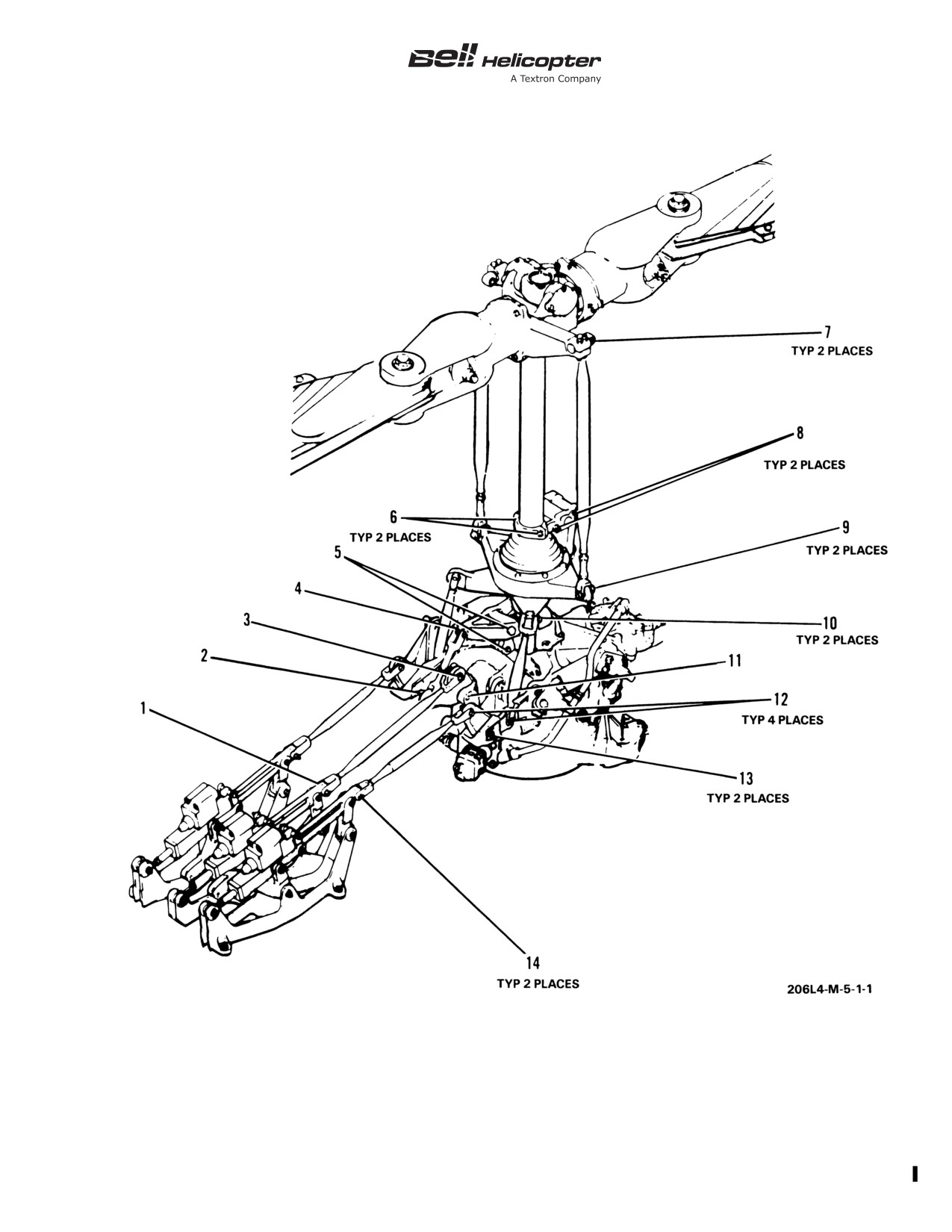
Remove main rotor flight control bolts/nuts (1 through 14,
Figure 5-2).
2.
Clean bolts/nuts with MEK (C-309). Wipe dry.
3.
Visually inspect bolts/nuts for corrosion and thread
damage. Replace any bolts/nuts that have damaged threads,
detectable wear and/or corrosion pitting.
4.
Apply a coating of corrosion preventive compound (C-104)
to all bolt shanks prior to installation. Do not apply corrosion
preventive compound to bolt threads.
5.
Install flight control bolts and attaching hardware. Torque
nuts and install new cotter pins.
6.
Apply a coating of corrosion preventive compound (C-101)
to all bolt heads, washers, nuts, and exposed threads after
installation.
NOTE
Operation in environmental conditions that erode
corrosion preventive compound (C-101) may require
periodic touch-up of corrosion preventive compound.
Before touch-up, visually check exposed surfaces for
evidence of corrosion. If corrosion is detected,
accomplish step 1 through step 6.
Page 107
BHT-206L4-MM-1
SCHEDULED INSPECTIONS
5-35.
24-MONTH INSPECTION (CONT)
INITIAL
DATA REFERENCE
INSPECTION TASK DESCRIPTION
MECH OTHER
FUEL SYSTEM
Chapter 28
1.
Remove fuel boost pump assemblies and inspect fuel cell
interiors for debris, water contamination, and fungus growth.
2.
Remove, clean, and inspect fuel manifold assembly.
3.
Remove, clean, and inspect inline fuel filters and check
valves.
Page 108
Rev. 20
7 NOV 2014
Export Classification C,
BHT-206L4-MM-1
Figure 5-2. Inspection of Main Rotor Flight Control Bolts/Nuts (Sheet 1 of 2)
Export Classification C,
7 NOV 2014
Rev. 20
Page 109

BHT-206L4-MM-1
Figure 5-2. Inspection of Main Rotor Flight Control Bolts/Nuts (Sheet 2 of 2)
Page 110
Rev. 20
7 NOV 2014
Export Classification C,
BHT-206L4-MM-1
SCHEDULED INSPECTIONS
5-36.
60-MONTH INSPECTION
INITIAL
DATA REFERENCE
INSPECTION TASK DESCRIPTION
MECH OTHER
DATE: __________________W.O. _____________________
FACILITY: _________________________________________
HELICOPTER S/N: __________________________________
REGISTRY NO.: ____________________________________
TOTAL TIME:_______________________________________
SIGNATURE:_______________________________________
BHT-206L4-MM
FREEWHEEL ASSEMBLY
BHT-206L-CR&O
NOTE
This inspection applies to helicopters equipped with
freewheel
assembly
406-040-500-143
(or
subsequent).
Do this inspection if an overhaul of the applicable
freewheel assembly has not been accomplished in
the last 60 months.
1.
Remove the freewheel assembly.
2.
Disassemble the freewheel assembly.
NOTE
Do not do a non-destructive inspection. It is not
necessary to remove paint from the parts.
3.
Examine the parts of the freewheel assembly for condition.
4.
Restore the surface finish of the damaged part(s), as
applicable.
5.
Assemble the freewheel assembly.
6.
Install the freewheel assembly.
7 JUN 2013
Rev. 18
Page 111/112
Export Classification C,
BHT-206L4-MM-1
SCHEDULED INSPECTIONS
5-37.
300-HOUR OR 12-MONTH INSPECTION
INITIAL
DATA REFERENCE
INSPECTION TASK DESCRIPTION
MECH OTHER
DATE: __________________W.O. _____________________
FACILITY: _________________________________________
HELICOPTER S/N: __________________________________
REGISTRY NO.: ____________________________________
TOTAL TIME:_______________________________________
SIGNATURE:_______________________________________
NOTE
This inspection is only applicable when conducting
the
100-hour airframe progressive or
100-hour
airframe periodic inspection program.
BHT-ELEC-SPM
BATTERY
Remove battery and recondition according to the
BHT-ELEC-SPM and manufacturer's service manual. Inspect
vent lines for obstructions or damage. Clean battery mounting
area prior to installing serviceable battery.
7 NOV 2014
Rev. 20
Page 113/114
Export Classification C,
BHT-206L4-MM-1
SCHEDULED INSPECTIONS
5-38.
600-HOUR OR 12-MONTH INSPECTION
INITIAL
DATA REFERENCE
INSPECTION TASK DESCRIPTION
MECH OTHER
DATE: __________________W.O. _____________________
FACILITY: _________________________________________
HELICOPTER S/N: __________________________________
REGISTRY NO.: ____________________________________
TOTAL TIME:_______________________________________
SIGNATURE:_______________________________________
Chapter 96
ELECTRICAL
1.
Perform operational
test
of
internal
battery
overtemperature switches.
Chapter 63
2.
Remove rotor tachometer generator.
a. Remove, examine, and lubricate the rotor tachometer
generator internal drive splines and input shaft splines
(TB
206L-09-235).
Page 115/116
BHT-206L4-MM-1
SCHEDULED INSPECTIONS
5-39.
1200 HOURS OF COMPONENT OPERATION
INITIAL
DATA REFERENCE
INSPECTION TASK DESCRIPTION
MECH OTHER
DATE: __________________W.O. _____________________
FACILITY: _________________________________________
HELICOPTER S/N: __________________________________
REGISTRY NO.: ____________________________________
TOTAL TIME:_______________________________________
SIGNATURE:_______________________________________
BHT-206L-CR&O
MAIN ROTOR HUB ASSEMBLY
1.
lnspect yoke and trunnion bearing surfaces for brinelling.
2.
lnspect yoke, latch bolts, strap pins, strap fittings, trunnion,
pillow blocks, grips, and pitch horns for corrosion.
3.
Visually inspect all hub components for excessive wear or
damage.
Page 117/118
BHT-206L4-MM-1
SCHEDULED INSPECTIONS
5-40.
1500 HOURS OF COMPONENT OPERATION
INITIAL
DATA REFERENCE
INSPECTION TASK DESCRIPTION
MECH OTHER
DATE: __________________W.O. _____________________
FACILITY: _________________________________________
HELICOPTER S/N: __________________________________
REGISTRY NO.: ____________________________________
TOTAL TIME:_______________________________________
SIGNATURE:_______________________________________
Chapter 63
MAIN ROTOR MAST
BHT-206A/B/L-Series-
CR&O
1.
Remove, disassemble, and clean main rotor mast.
2.
Inspect main rotor mast as follows:
a. Visually inspect mast splines for burrs, nicks, cracks,
and wear. Indication of wear requires an over pins dimensional
check.
b. Visually inspect mast inner and outer surfaces for
corrosion. Inspect surface protective coatings for condition.
c. Visually inspect bearing balls and races for pits,
erosion, spalling, and brinelling.
3.
Reassemble and install main rotor mast.
1 JUN 2012
Rev. 16
Page 119
BHT-206L4-MM-1
SCHEDULED INSPECTIONS
5-40.
1500 HOURS OF COMPONENT OPERATION (CONT)
INITIAL
DATA REFERENCE
INSPECTION TASK DESCRIPTION
MECH OTHER
TRANSMISSION
NOTE
This inspection is applicable to transmission
assemblies that have been operated with
MIL-PRF-7808 oil since new or since last overhaul.
To increase the inspection interval to 2250 Hours or
60 months, the transmission must have been
operated with DOD-PRF-85734 oil since new or
since the last overhaul (TB 206L-04-213).
Chapter 63
1.
If installed on the helicopter, remove the transmission
assembly.
2.
Remove the mast and swashplate assembly from the
transmission assembly.
3.
Inspect oil filter for debris and metal contamination.
BHT-206L-CR&O
4.
Remove the transmission top case, the planetary
assembly, and the sun gear.
5.
Visually examine all removed components for condition.
6.
Insert a mirror between the spiral bevel gear edge and the
lower case and use a bright light to examine the spiral bevel
gear, input pinion gears, and surrounding areas for condition.
7.
Reassemble the transmission.
Chapter 63
8.
Install the mast and swashplate assembly into the
transmission assembly.
9.
Apply sealant, primer, and paint to the required areas.
10. Install the transmission assembly into the helicopter.
Chapter 12
11. Service the transmission with oil.
Page 120
Rev. 16
1 JUN 2012
BHT-206L4-MM-1
SCHEDULED INSPECTIONS
5-41.
2250 HOURS OR 60 MONTHS OF COMPONENT OPERATION
INITIAL
DATA REFERENCE
INSPECTION TASK DESCRIPTION
MECH OTHER
DATE: __________________W.O. _____________________
FACILITY: _________________________________________
HELICOPTER S/N: __________________________________
REGISTRY NO.: ____________________________________
TOTAL TIME:_______________________________________
SIGNATURE:_______________________________________
TRANSMISSION
NOTE
This inspection is applicable to transmission
assemblies 206-040-004-115 and subsequent that
have been operating with DOD-PRF-85734 oil since
new or since last overhaul (TB 206L-04-213).
If
the transmission has been operated with
MIL-PRF-7808 oil, the 1500 Hours Of Component
Operation scheduled inspection applies.
Chapter 63
1.
If installed on the helicopter, remove the transmission
assembly.
2.
Remove the mast and swashplate assembly from the
transmission assembly.
3.
Inspect oil filter for debris and metal contamination.
BHT-206L-CR&O
4.
Remove the transmission top case, the planetary
assembly, and the sun gear.
5.
Visually examine all removed components for condition.
6.
Insert a mirror between the spiral bevel gear edge and the
lower case and use a bright light to examine the spiral bevel
gear, input pinion gears, and surrounding areas for condition.
Page 121
BHT-206L4-MM-1
SCHEDULED INSPECTIONS
5-41.
2250 HOURS OR 60 MONTHS OF COMPONENT OPERATION (CONT)
INITIAL
DATA REFERENCE
INSPECTION TASK DESCRIPTION
MECH OTHER
7.
Reassemble the transmission.
Chapter 63
8.
Install the mast and swashplate assembly into the
transmission assembly.
9.
Apply sealant, primer, and paint to the required areas.
10. Install the transmission assembly into the helicopter.
Chapter 12
11. Service the transmission with oil (DOD-PRF-85734).
Page 122
BHT-206L4-MM-1
SCHEDULED INSPECTIONS
5-42.
3000 HOURS OF COMPONENT OPERATION
INITIAL
DATA REFERENCE
INSPECTION TASK DESCRIPTION
MECH OTHER
DATE: __________________W.O. _____________________
FACILITY: _________________________________________
HELICOPTER S/N: __________________________________
REGISTRY NO.: ____________________________________
TOTAL TIME:_______________________________________
SIGNATURE:_______________________________________
BHT-206L-CR&O
TAIL ROTOR GEARBOX
NOTE
This inspection may be accomplished concurrently
with the duplex bearing (206-040-410-005, -101, or
subsequent) replacement at 3000 hours.
1.
Perform backlash check of the gearbox prior to
disassembly. Backlash shall be 0.003 to 0.011 inch (0.08 to
0.28 mm) and shall not vary more than 0.002 inch (0.05 mm)
when measured at three different locations. Record backlash for
later reference.
NOTE
If this inspection is being done in conjunction with
replacement of bearing (206-040-410-005, -101, or
subsequent), removal of input pinion assembly is not
required. Remove output cap, output shaft, and
duplex bearing
(206-040-410-005,
-101, or
subsequent) after complying with step 1.
2.
Remove input pinion and bearings. Remove output cap
and oil level sight glass.
3.
Inspect spiral bevel gear and input pinion gear for
corrosion and chipped, broken, or worn gear teeth. Inspect gear
wear patterns.
Page 123
BHT-206L4-MM-1
SCHEDULED INSPECTIONS
5-42.
3000 HOURS OF COMPONENT OPERATION (CONT)
INITIAL
DATA REFERENCE
INSPECTION TASK DESCRIPTION
MECH OTHER
4.
Visually inspect accessible areas of input pinion duplex
bearing, input pinion roller alignment bearing, and output shaft
roller alignment bearing and race for roughness, spalling,
scoring, pitting, flaking, broken or damaged retainers, and for
evidence of overheating and corrosion.
5.
Visually inspect studs and dowel pins in case assembly for
security and damage. Replace damaged studs and/or dowel
pins.
6.
lnspect accessible areas of case and output cap for
corrosion and damage.
7.
Inspect sight glass for cracking, crazing, or any condition
that may obscure level or color of oil. Inspect oil level indicator
for discoloration, peeling paint, or evidence of a plastic film on
painted side. Remove plastic film if present.
8.
Reassemble gearbox. Exercise caution when inserting
input pinion assembly, if previously removed, to ensure proper
gear mesh with spiral bevel gear.
9.
Check gearbox backlash. Measured values shall be within
0.001 inch (0.03 mm) of those obtained in step 1.
NOTE
If input pinion and spiral bevel gear were replaced at
this time, backlash figures may not fall within
0.001 inch (0.03 mm) of those obtained in step 1.
Backlash shall, however, fall within overhaul limits.
10. Apply sealant and touch up finish as required.
Page 124
BHT-206L4-MM-1
SPECIAL INSPECTIONS
5-43. SPECIAL INSPECTIONS
•
1 to 5 hours after each installation
Accomplish the following special inspections on the
•
3 to 8 hours after each installation
helicopter (paragraph 5-44 through paragraph 5-48):
•
10 to 25 hours after each installation
• After fuel system maintenance and/or
component change
•
100 hours after each installation
Page 125/126
BHT-206L4-MM-1
SPECIAL INSPECTIONS
5-44. AFTER FUEL SYSTEM MAINTENANCE AND/OR COMPONENT CHANGE
INITIAL
DATA REFERENCE
INSPECTION TASK DESCRIPTION
MECH OTHER
DATE: __________________W.O. _____________________
FACILITY: _________________________________________
HELICOPTER S/N: __________________________________
REGISTRY NO.: ____________________________________
TOTAL TIME:_______________________________________
SIGNATURE:_______________________________________
NOTE
Accomplish immediately after fuel system
maintenance and/or component change/removal, at
an adequate maintenance facility.
Chapter 28
FUEL SYSTEM
NOTE
Installation and removal of a fuel boost pump
cartridge, fuel quantity probe, or fuel drain valve does
not require this inspection.
If fuel system maintenance and/or component change/removal
is performed at a site remote from an adequate maintenance
facility, accomplish step 1, substep c through substep e, and
step 3, or step 2 and step 3, as applicable, prior to flight. Upon
return to an adequate maintenance facility, but not to exceed 10
flight hours, accomplish entire inspection.
1.
When maintenance or component change/removal is
conducted below the top fitting of the aft fuel cell immediately
following fuel system maintenance and/or major component
change/removal
(boost pump assembly, manifold, flow
switches, inline filters, ejector pumps, check valves, fuel line or
hoses), ground run helicopter and check for air and fuel leaks
and for proper operation as follows:
Page 127
BHT-206L4-MM-1
SPECIAL INSPECTIONS
5-44. AFTER FUEL SYSTEM MAINTENANCE AND/OR COMPONENT CHANGE (CONT)
INITIAL
DATA REFERENCE
INSPECTION TASK DESCRIPTION
MECH OTHER
Chapter 12
a. Make sure all fuel has been drained from aft and
forward fuel cells.
b. Service fuel cell with 10 gallons (37.9 L) of fuel.
BHT-206L4-FM-1
c. Perform normal engine starting and run-up checks.
d. Set throttle to full open and operate engine at 100% N2
for a minimum of 2 minutes with both fuel boost pumps OFF. If
flameout or power loss occurs, refer to step 3.
e. Perform normal engine shutdown.
f. Select fuel quantity switch to forward position to ensure
fuel transfer from aft to forward fuel cells has not taken place.
2.
When maintenance and/or component change is
conducted above the top fitting of the fuel cell, immediately
following the fuel system maintenance and/or component
change/removal
(fuel pressure transducer, fuel valve,
scheduled fuel component change/removal fuel line or hose),
ground run helicopter and check for air or fuel leaks and for
proper operation as follows:
BHT-206L4-FM-1
a. Perform normal engine start and run-up checks.
b. Set throttle to full open and operate engine at 100% N2
for a minimum of 2 minutes with both fuel pumps OFF. If
flameout or power loss occurs, refer to step 3.
3.
If flameout or power loss occurs, air is entering the
helicopter or engine fuel system, or an engine pneumatic leak
exists. Malfunction must be corrected before commencing flight
operations.
a. Verify fuel boost pump, check valve, and fuel shutoff
valve for proper operation.
b. Make sure all hoses and lines are serviceable and do
not have cracked flares and that B nuts are correctly torqued.
Page 128
BHT-206L4-MM-1
SPECIAL INSPECTIONS
5-44. AFTER FUEL SYSTEM MAINTENANCE AND/OR COMPONENT CHANGE (CONT)
INITIAL
DATA REFERENCE
INSPECTION TASK DESCRIPTION
MECH OTHER
Rolls-Royce 250-C30
c. Purge air from fuel system and accomplish pneumatic
Series Operation and
leak check.
Maintenance Manual,
14W2
Page 129/130