SANY Crawler Hydraulic Excavator SY365H-9, SY365BH-9. Shop Manual (2014) - page 19
 

  Index      Manuals     SANY Crawler Hydraulic Excavator SY365H-9, SY365BH-9. Shop Manual (2014)


Search            copyright infringement  


Content      ..     17      18      19      20     ..


SANY Crawler Hydraulic Excavator SY365H-9, SY365BH-9. Shop Manual (2014) - page 19


4-210

Structure and Functions

SY365(B)H-9 Crawler Hydraulic Excavator

4.11.3.15 Machine con

fi

 guration setup

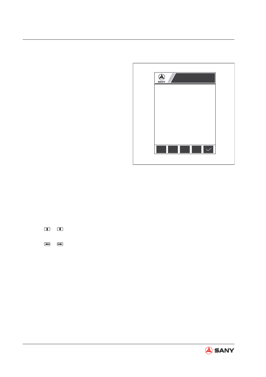
Select Machine Configuration Setup on the 
page of System Setup and press F2 or Enter 
to enter the page.

This page is used to set up machine con

fi

 gu-

ration after monitor installation.

Note

: Access to System Setup requires en-

tering the password. For method of entering 
password see 

“

Password entry to system 

information

”

 on page 4-202

.

Key operation

●

When 

“

215

”

 after machine model is

blinking, each pressing of F1 will bring the
number up by 10; when 

“

32

”

 after GPS

is blinking, each pressing of F1 will bring
the number up by 10.

●

Press F2 to change Engine Model.

●

Press F3 to change Hydraulic System
Model.

●

Press F4 to change controller model.

●

Press F5 to save the change. You will
see on the screen 

“

Calibration finished!

Please restart your machine.

”

●

Press

 or

 to increase or decrease the

selected machine S/N by 100.

●

Press

 or

 to increase or decrease the

selected machine S/N by 1. Depress the
key to increase S/N quickly.

●

Press ESC to return to System Setup.

●

Each pressing of the key Enter enables
the number after machine S/N or model to
blink. A blinking number can be modified
using the keys.

XP2051203023

Machine Configuration Setup

Machine Model

:

SY215C\GPS 32

Engine Model

:

CUMMINS_II

HYD SYS Model

:

KPM P

Controller Model

:

KC-MB-001

Machine S/N

:

11SY0216 00008

Use [

↑

][

↓

][

←

] and [

→

] to change machine S/N.

Model Eng

Hyd

Ctrl

Fig. 4-227 

4-211

Structure and Functions

SY365(B)H-9 Crawler Hydraulic Excavator

4.11.3.16  Hydraulic oil temperature

Select Hydraulic Oil Temp on the page of Sys-
tem Setup and press F2 or Enter to enter the 
page.

This page shows temperature of hydraulic oil.

Key operation


●

Press F5 or ESC to return to System Set-
up.

4.11.3.17  Screen brightness setup

Press F4 on the page of password entry to 
system information to enter the page.

This page is used to adjust backlight bright-
ness of the screen.

Key operation


●

Press F1 to dim backlight.


●

Press F2 to enhance backlight.


●

Press F3 to safe brightness change.


●

Press F5 to return to System Information.

XP2051203028

HYD Oil Temp

Hydraulic Oil Temp 

℃:

49

Fig. 4-228 

XP2051203029

Press F3 to save setup

!

Screen Brightness Setup

Screen Brightness

:

20%

Fig. 4-229 

4-212

Structure and Functions

SY365(B)H-9 Crawler Hydraulic Excavator

4.11.3.18  System lockout (level 1)

When this page appear on monitor, it indicates 
that the excavator is locked out in level 1.

Key operation

●

Press F5 to enter the page for unlocking.

NOTE

: After 5 seconds according to the com-

mand, corresponding state (Level 1 lockout, 
level 2 lockout or no lockout) will be displayed. 
(Waiting for 5 seconds performs a function of 

fi

 ltration.)

4.11.3.19  System lockout (level 2)

When this page appear on monitor, it indicates 
that the excavator is locked out in level 2.

Key operation

●

Press F5 to enter the page for unlocking.

NOTE

: After 5 seconds according to the com-

mand, corresponding state (Level 1 lockout, 
level 2 lockout or no lockout) will be displayed. 
(Waiting for 5 seconds performs a function of 

fi

 ltration.)

XP2051203024

System Lockout

Machine Model

:

SY205C

Machine S/N

:

00008

Lockout State

:

Level 1

Current time

:

12

:

12

:

11

System Locked

Contact your Sany distributor to unlock your machine.

Fig. 4-230 

Fig. 4-231 

XP2051203025

System Lockout

Machine Model

:

SY205C

Machine S/N

:

00008

Lockout State

:

Level 2 

Current time

:

12

:

12

:

11

System Locked

Contact your Sany distributor to unlock your machine.

Standard Values

Standard Values

SY365(B)H-9 Crawler Hydraulic Excavator

5-1

5  Table of Standard Values

5.1  Standard Values for Engine-Related Parts .............................................................. 5-3
5.2  Standard Values for Chassis-Related Parts ............................................................ 5-4

5-3

Standard Values

SY365(B)H-9 Crawler Hydraulic Excavator

Applicable Models

SY365(B)H-9

Engine

ISUZU AA-6HK1-XQP-01

Item

Measurement condition

Unit

Standard values for 

new machine

Repair limits

Engine speed

High idling

rpm

2,250 

±

 25

2,250 

±

 25

Low idling

rpm

1,050 

±

 25

1,050 

±

 25

Rated speed

rpm

2,000

2,000

Intake pressure

 (Negative 

pressure) 

Air cleaner outlet location

Arm-in relief

+

max rpm

kPa

{mmH

2

O}

Min 133

{Min 1,000}

Min 133

{Min 1,000}

Exhaust color

At sudden acceleration

Bosch

Index

Max 25

35

At high idling

—

—

Valve clear-

ance

Intake valve

mm

0.4

0.3– 0.5

Exhaust valve

mm

0.4

0.3 – 0.5

Compression 

pressure

Oil temp

:

75

℃

Engine speed 250 rpm

Mpa

{kg/cm

2

}

Min 3.0

{31}

2.5

{26}

Blow-by pres-

sure

Coolant temp

:

working range arm-

in relief

+

max rpm

kPa

{mmH

2

O}

Max 0.98

{Max 100}

1.96

{200}

Engine oil pres-

sure

High idling

MPa

{kg/cm

2

}

Min 0.29

{Min 3.0}

0.25

{2.5}

Low idling

MPa

{kg/cm

2

}

Min 0.10

{Min 1.0}

0.07

{0.7}

Engine oil temp

Full speed range (in oil pan) 

℃

80 – 110

120

Fan belt ten-

sion

Between fan belt pulley and alterna-

tor belt pulley

De

fl

 ection when pressed with 

fi

 nger 

force of 58.8 N {6 kg}

mm

8.5

Min 7

,

Max 10

A/C compres-

sor belt tension

Between fan belt pulley and com-

pressor belt pulley

De

fl

 ection when pressed with 

fi

 nger 

force of 58.8 N {6 kg}

mm

5 – 8

5 – 8

5  TABLE OF STANDARD VALUES

5.1  Standard Values for Engine-Related Parts

5-4

Standard Values

SY365(B)H-9 Crawler Hydraulic Excavator

5.2  Standard Values for Chassis-Related Parts

Applicable Models

SY365(B)H-9

cate-

gory

Item

Measurement Condition

Unit

Standard Value 

for New Ma-

chine

Permissible 

Value

       Engine Speed

2 pumps at relief


●

Engine coolant temperature: Within 
operational range


●

Hydraulic oil temperature: Within 
operational range


●

Engine running at high idle


●

Heavy-load operating mode (H)


●

Arm-in relief condition

rpm

2,050

±

50

2,050

±

50

2 pumps at relief + 
boosting (if avail-
able)


●

Engine coolant temperature: Within 
operational range


●

Hydraulic oil temperature: Within 
operational range


●

Engine running at high idle


●

Heavy-load operating mode (H)


●

Arm-in relief condition + boost switch 
on

rpm

2,050

±

50

2,050

±

50

Speed when auto 
deceleration is op-
erated


●

Engine running at high idle


●

Auto idling switch on 


●

All control levers neutral

rpm

1,350

±

50

1,400

±

100

Spool Stroke

Boom control valve


●

Engine stopped


●

For measur-
ing points see 
Control Valve 
on page 3-10.

Raise

mm

11.5

±

0.5

11.5

±

0.5

Lower

mm

9.5

±

0.5

9.5

±

0.5

Arm control valve

In

mm

11.5

±

0.5

11.5

±

0.5

Out

mm

9.5

±

0.5

9.5

±

0.5

Bucket control valve

Curl/dump

mm

9.5

±

0.5

9.5

±

0.5

Swing control valve

Travel (L&R)

mm

9.5

±

0.5

9.5

±

0.5

Travel control valve

Forward & Reverse

mm

9.5

±

0.5

9.5

±

0.5

T

ravel of Control Lever

Boom control lever


●

Engine stopped


●

Control lever grip at center


●

Max. reading up to stroke end (except 
lever play in NEUTRAL  position)

mm

85

±

10

85

±

10

Arm control lever

mm

85

±

10

85

±

10

Bucket control lever

mm

85

±

10

85

±

10

Swing control lever

mm

85

±

10

85

±

10

Travel control lever

mm

115

±

12

115

±

12

Play of control lever


●

Engine stopped


●

S l i g h t l y   p u s h 
the control lever 
with your hand. 
S t o p   p u s h i n g 
when you feel 
clear resistance 


●

Max. reading up 
to stroke end

Work Equipment

mm

Max 15

Max 20

Travel

mm

Max 20

Max 25

5-5

Standard Values

SY365(B)H-9 Crawler Hydraulic Excavator

Applicable Models

SY365(B)H-9

Cate-
gory

Item

Measurement Condition

Unit

Standard Value for 

New Machine

Permissible 

Value

Operating Force of Control Lever  and 

Pedal

Boom control 
lever


●

Hydraulic oil temp

:

Within op-

erational range


●

Engine running at high idle


●

Control lever grip at center


●

Pedal at tip


●

Max reading at stroke end

N

{kg}

Max 19.6

{Max 2.0}

Max 24.5

{Max 2.5}

Arm control 
lever

Max 19.6

{Max 2.0}

Max 24.5

{Max 2.5}

Bucket con-
trol lever

Max 15.6

{Max 1.6}

Max 21.6

{Max 2.2}

Swing control 
lever

Max 15.6

{Max 1.6}

Max 21.6

{Max 2.2}

Travel control 
lever

Max 30.4

{Max 3.1}

Max 39.2

{Max 4.0}

Travel control 
pedal

Max 93.1

{Max 9.5}

Max 107.6

{Max 11}

Hydraulic Pressure

Unloaded 
pressure


●

Hydraulic oil temp

:

Within op-

erational range


●

Engine running at high idle


●

Working mode

:

H 


●

Hydraulic pump output pressure 
with all control levers in neutral 
position

MPa

{kg/cm

2

}

3.5 

±

 1.0

{36 

±

 10}

3.5 

±

 1.0

{36 

±

 10}

Boom relief


●

Hydraulic oil temp

:

Within op-

erational range


●

Operate corresponding control 
lever after the engine runs at 
high idling speed.


●

Working mode

:

H 


●

Hydraulic pump output pressure 
with all measurement circuits 
relieved

34.3 

±

 1.0

{350 

±

 10}

33.3 – 35.3

{340 – 360}

Arm relief

34.8 

±

 1.0

{355 

±

 10}

33.3 – 36.8

{340 – 375}

Bucket relief

34.8 

±

 1.0

{355 

±

 10}

33.3 – 36.8

{340 – 375}

Swing relief


●

Hydraulic oil temp

:

Within op-

erational range


●

Operate corresponding control 
lever after the engine runs at 
high idling speed.


●

Working mode

:

H 


●

Hydraulic pump output pressure 
with all measurement circuits 
relieved

25.5 

±

 1.0

{261 

±

 10}

24.5 

-

 27.5

{250 

-

280}

Travel relief

33.4 

±

 1.0

{342

±

10}

32.4 – 34.4

{330 – 351}

Control circuit 
source pres-
sure


●

Hydraulic oil temp

:

Within op-

erational range


●

Engine running at high idle


●

Self pressure reducing valve 
output pressure with all control 
levers in NEUTRAL position

3.9

±

0.2

{40

±

2}

3.7 – 4.1

{37 – 41}

5-6

Standard Values

SY365(B)H-9 Crawler Hydraulic Excavator

Applicable Models

SY365(B)H-9

Cate-

gory

Item

Measurement Condition

Unit

Standard Value 

for New Ma-

chine

Permissible 

Value

Swing

Swing brake angle

●

Hydraulic oil temp

:

Within operational range

●

Engine running at high idle

●

Working mode: H

●

Swing circle misalignment amount when stopping
after one turn

●

For measuring posture see Swing 1 on page
3-10.

degree

mm

Max 100

 (

—

) 

Max 130

 (

—

) 

T

ime taken to start 

swing

●

Hydraulic oil temp

:

Within opera-

tional range

●

Engine running at high idle

●

Working mode: H

●

Time required for passing points
90

°

and 180

°

 from starting point

●

For measuring posture see Swing
1 on page 3-10.

90

°

sec.

3.1 

±

 0.3

Max 3.7

180

°

sec.

4.4 

±

 0.4

Max 5.5

T

ime taken to swing

●

Hydraulic oil temp

:

Within operational range

●

Engine running at high idle

●

Working mode: H

●

Time required for 5 turns after making initial one
turn

●

For measuring posture see Swing 1 on page
3-10.

sec.

31

+4 

-2

Max 35

Hydraulic drift

●

Hydraulic oil temp

:

Within operational range

●

Engine stopped

●

Keeping the upper structure transverse on a
grade of 15

°

. For more information see Swing 2

on page 3-10.

●

Notching a mating mark on inner and outer races
of the swing circle

●

Mating mark misalignment amount during 5 min-
utes.

mm

0

0

Motor leak-

age

●

Hydraulic oil temp

:

Within operational range

●

Engine running at high idle

●

Swing lockout switch: ON

●

Leakage amount for one minute during swing
relief

ml/min

Max  5

Max 10

T

ravel

T

ravel speed

(unloaded)

●

Hydraulic oil temp

:

Within opera-

tional range

●

Engine running at high idle

●

Working mode: H

●

Time required for track shoes to
make 5 turns after making one
initial turn

●

For more information on measur-
ing posture see Travel 1 on page
3-11.

Lo

sec.

11.8

±

 3

8.8-14.8

Hi

7.6 

±

 3

4.6-10.6

5-7

Standard Values

SY365(B)H-9 Crawler Hydraulic Excavator

Applicable Models

SY365(B)H-9

Cate-

gory

Item

Measurement Condition

Unit

Standard 

Value for New 

Machine

Permissible 

Value

T

ravel

T

ravel speed

(Actual run)

●

Hydraulic oil temp

:

Within operational range

●

Engine running at high idle

●

Working mode: H

●

Level ground

●

Time required for traveling 10 m after 10 m trial
run

●

For measuring posture see Swing 2 on page 3-10.

Lo

sec.

22 

±

 2.5

19.5-24.5

Hi

14 

±

 2.5

11.5-16.5

Deviation

●

Hydraulic oil temp

:

Within operational range

●

Engine running at high idle

●

Working mode: H

●

Travel Speed: Low

●

Hard level ground

●

Amount of deviation (

χ

) while traveling 20 m after ini-

tial 10 m trial run

●

For measuring posture see Travel 2 and 3 on page
3-11.

mm

Max 800

Max 900

Hydraulic drift

●

Hydraulic oil temp

:

Within operational range

●

Engine stopped

●

Park the machine on a grade of 12

°

, with the sprock-

et in the downhill direction

●

Measure the sliding distance for 5 minutes

●

For measuring posture see Travel 4 on page 3-12.

mm

0

0

Leakage 

amount of 

travel motor

●

Hydraulic oil temp

:

Within operational range

●

Engine running at high idle

●

Traveling with the sprocket locked

●

Oil leakage amount for one minute with traveling in re-
lief condition

mm

13.6

27.2

W

ork Equipment

Hydraulic drift

Bucket 

tips

●

Hydraulic oil temp: Within operational range

●

Flat and level ground

●

Bucket full of earth or with rated load (0.8m

3

: 1,440 kg)

●

Boom horizontal, arm fully retracted and bucket cylin-
der fully extended

●

Engine stopped

●

Work equipment control lever in neutral position

●

Measure total amount of falling for 15 minutes by mea-
suring the falling every 5 minutes immediately after ini-
tial setting


★

Bucket tip lower distance


★

Boom cylinder: Cylinder retracting distance


★

Arm cylinder: cylinder extending distance


★

Bucket cylinder: cylinder retracting distance

●

For measuring posture see Work Equipment 1 on page 
3-12. 

mm

Max 600

Max 900

Boom 

cylinder

mm

Max 20

Max 27

Arm cylin-

der

mm

Max 20

Max 20

Bucket cylinder

mm

Max 35

Max 40

5-8

Standard Values

SY365(B)H-9 Crawler Hydraulic Excavator

Applicable Models

SY365(B)H-9

Cate-

gory

Item

Measurement Condition

Unit

Standard Value for 

New Machine

Permissible 

Value

W

ork Equipment

W

ork Equipment Speed

Boom


●

Hydraulic oil temp

:

Within op-

erational range


●

Engine running at high idle


●

Working mode: H


●

Time required for the bucket 
to raise from the ground to its 
stroke end


●

For measuring posture see 
Work Equipment 2 on page 
3-12. 

UP

sec.

3.8 

±

 0.3

Max 4.8

Arm


●

Hydraulic oil temp

:

Within op-

erational range


●

Engine running at high idle


●

Working mode: H


●

Time required from dumping 
stroke end to digging stroke end


●

For measuring posture see 
Work Equipment 3 on page 
3-13. 

IN

sec.

3.5 

±

 0.3

Max 4.5

OUT

sec.

3.0

±

 0.3

Max 3.5

Bucket


●

Hydraulic oil temp

:

Within op-

erational range


●

Engine running at high idle


●

Working mode: H


●

Time required from dumping 
stroke end to digging stroke end


●

For measuring posture see 
Work Equipment 4 on page 
3-13. 

DIG

sec.

3.1 

±

 0.3

Max 3.4

DUMP

sec.

2.0 

±

 0.3

Max 2.3

5-9

Standard Values

SY365(B)H-9 Crawler Hydraulic Excavator

Applicable Models

SY365(B)H-9

Cate-

gory

Item

Measurement Condition

Unit

Standard Value 

for New Machine

Judgement 

Criteria

W

ork Equipment

T

ime Delay

Boom


●

Hydraulic oil temp

:

Within opera-

tional range


●

Engine running at low idle


●

Working mode: H


●

Time required from maneuvering 
the joystick to the moment that the 
bucket reaches the ground and 
begins to push the machine up-
ward, within 50 mm off the ground


●

For measuring posture see Work 
Equipment 5 on page 3-13.

sec.

Max  1.0

Max 1.2

Arm


●

Hydraulic oil temp

:

Within opera-

tional range


●

Engine running at low idle


●

Working mode: H


●

Average time required for operat-
ing the control lever back and forth 
till the arm starts to move


●

For measuring posture see Work 
Equipment 6 on page 3-14.

sec.

Max  2.0

Max 2.8

Bucket


●

Hydraulic oil temp

:

Within opera-

tional range


●

Engine running at low idle


●

Working mode: H


●

Average time required for operat-
ing the control lever back and forth 
till the arm starts to move


●

For measuring posture see Work 
Equipment 7 on page 3-14.

sec.

Max  1.0

Max 3.6

Internal Leakage

Cylinders


●

Hydraulic oil temp

:

Within opera-

tional range


●

Engine running at high idle


●

Leakage amount for one (1) min-
ute with cylinder or travel mea-
sured at relief condition

ml/min

5

20

Central 
Swivel 
Joint

10

50

Performance in Combined 

Operations

Amount of devia-
tion in simultane-
ous operation of 
work equipment 
and travel


●

Hydraulic oil temp

:

Within opera-

tional range


●

Engine running at high idle


●

Working mode: H


●

Travel Speed: Low


●

 Amount of deviation measured for 
20 m after traveling about 10 m on 
a hard level ground


●

For measuring posture see Travel 
2 and 3 on page 3-11.

mm

Max 200

Max 220

5-10

Standard Values

SY365(B)H-9 Crawler Hydraulic Excavator

ZX335-1003002

ZX335-1003004

15°

ZX335-1003006

Sprocket

Control valve: Spool stroke

Swing 1: Swing brake angle, time taken to 
start swing and time taken to swing

Swing 2: Hydraulic drift of swing

Machine attitudes applicable to perfor-
mance test and testing procedure of all 
machine models

Fig. 5-1 

Fig. 5-3 

Fig. 5-2 

5-11

Standard Values

SY365(B)H-9 Crawler Hydraulic Excavator

ZX335-1003003

45°

ZX335-1003005

x

10m

ZX335-1003007

Travel 1: Travel speed (without load)

Travel 2: Travel speed (actual run), Travel de-
viation

Travel 3: Travel deviation

Fig. 5-4 

Fig. 5-5 

Fig. 5-6 

5-12

Standard Values

SY365(B)H-9 Crawler Hydraulic Excavator

12°

ZX335-1003008

ZX335-1003010

ZX335-1003012

Travel 4: Hydraulic drift of travel

Work equipment 1: Hydraulic drift of work 
equipment

Work equipment 2: Boom speed

Fig. 5-7 

Fig. 5-8 

Fig. 5-9 

5-13

Standard Values

SY365(B)H-9 Crawler Hydraulic Excavator

ZX335-1003009

ZX335-1003011

ZX335-1003013

Work equipment 3: Arm speed

Work equipment 4: Bucket speed

Work equipment 5: Boom delay

Fig. 5-10 

Fig. 5-11 

Fig. 5-12 

5-14

Standard Values

SY365(B)H-9 Crawler Hydraulic Excavator

ZX335-1003014

ZX335-1003015

Work equipment 6: Arm delay

Work equipment 7: Bucket delay

Fig. 5-13 

Fig. 5-14 


Content      ..     17      18      19      20     ..