Suzki Burgman AN400. Manual - part 45


  Index      Motorcycles     Suzki Burgman AN400 - service and repair manual 2002 year


Search            


Content   ..  43  44  45  46   ..


Suzki Burgman AN400. Manual - part 45


5-18     FUEL SYSTEM AND THROTTLE BODY

CLEANING AND INSPECTION

• Clean all passageways with a spray-type carburetor cleaner

and blow dry with compressed air.

!

• Check following items any damage or clogging.
* Throttle shaft bushing and seal

* Fuel injector

* Throttle valve

* O-ring

* Idle adjust screw

* Throttle body

* Vacuum hose

* Intake pipe

* Injector seal

#

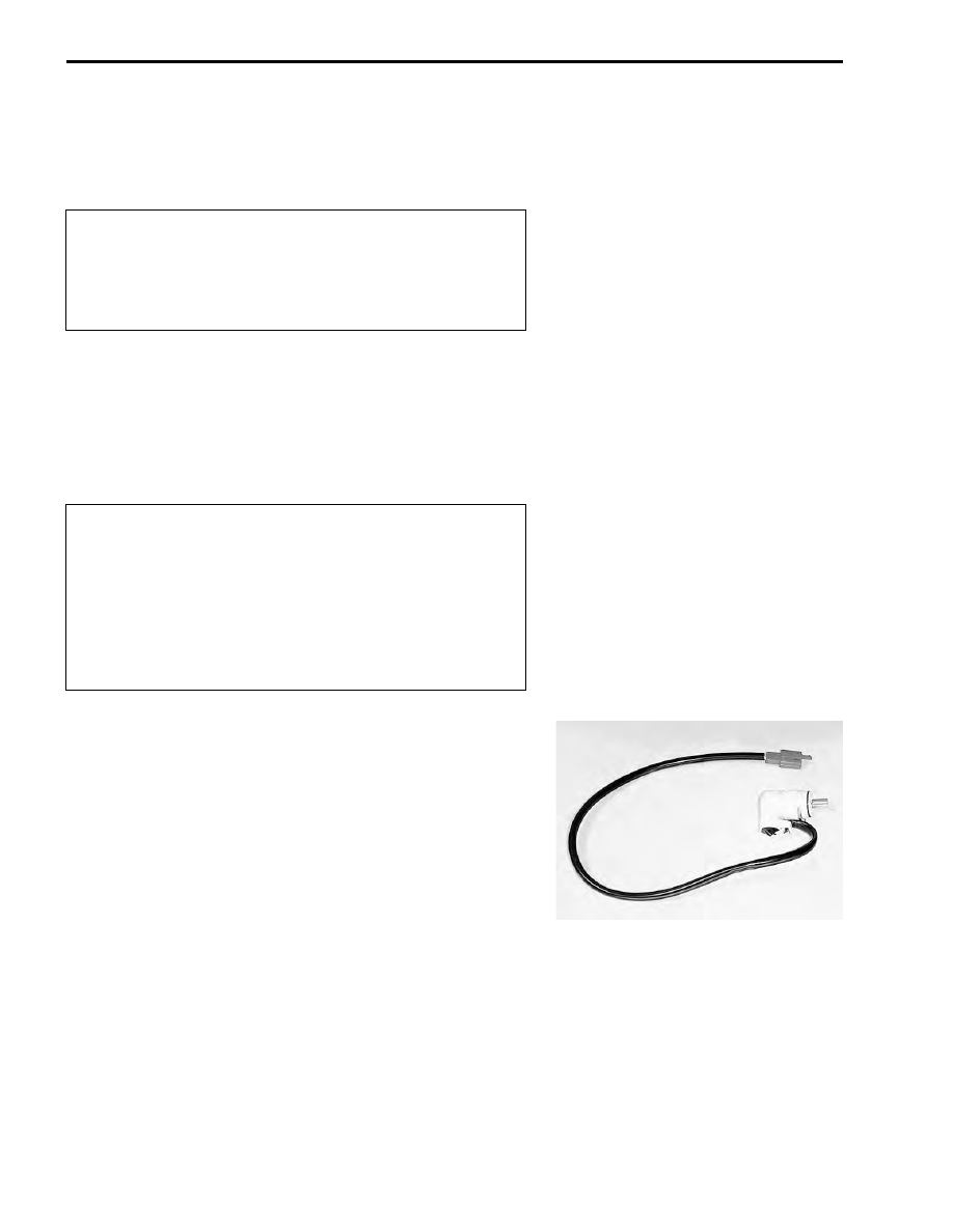
IAC VALVE INSPECTION

• The IAC valve can be checked without removing if from the

throttle body.

• Inspect the IAC valve. (

"

4-39)

Some carburetor cleaning chemicals, especially
dip-type soaking solutions, are very corrosive and
must be handled carefully. Always follow the chemical
manufacture’s instructions on proper use, handling
and storage.

Do not use wire to clean passageways. Wire can dam-
age passageways. If the components cannot be
cleaned with a spray cleaner it may be necessary to
use a dip-type cleaning solution and allow them to
soak. Always follow the chemical manufacturer’s
instructions for proper use and cleaning of the throttle
body components. Do not apply carburetor cleaning
chemicals to the rubber and plastic materials.

FUEL SYSTEM AND THROTTLE BODY     5-19

REASSEMBLY

• Reassemble the throttle body in the reverse order of disas-

sembly.

• Pay attention to the following points:
• Set the idle adjust screw 


1

 to the original position (amount of

turning back) where it was set before disassembly.

#

• Apply thin coat of the engine oil to the new O-ring.

• Install the O-ring 


2

 to the throttle body.

#

• Install the injector seal 


3

 and O-ring 


4

 to fuel injector.

• Apply thin coat of the engine oil to the new O-ring and new

seal.

• Install the fuel injectors by pushing them straight to throttle

body.

#

• Apply a small quantity of SUZUKI SUPER GREASE to the

shaft end and seal lip.

'

99000-25010: SUZUKI SUPER GREASE “A” (Others)
99000-25030: SUZUKI SUPER GREASE “A” (USA)

Replace the O-ring with a new one.

Replace the O-ring with a new one.

Replace the injector seal and O-ring with the new
ones. Never turn the injector while pushing it.

5-20     FUEL SYSTEM AND THROTTLE BODY

• With the throttle valve fully closed, install the TP sensor to the

original setting position.

%

TP sensor mounting screw: 3.5 N·m (0.35 kgf-m, 2.5 lb-ft)

• Install the IAC valve.

#

• Apply thin coat of the engine oil to the new O-ring.

INSTALLATION

• Installation is in the reverse order of removal. Pay attention to

the following points:

• With THREAD LOCK applied to the mounting bolts,  install the

PAIR control solenoid valve.

(

99000-32050: THREAD LOCK “1342”

• Insert the protrusions 


A

 of air cleaner box into the holes 


B

 of

its bracket.

THROTTLE CABLE ADJUSTMENT

• Adjustment can be made by the throttle grip side adjuster.

(

"

2-12)

Replace the O-ring with a new one.

FUEL SYSTEM AND THROTTLE BODY     5-21

TP SENSOR ADJUSTMENT

• After installing the throttle body, adjust the TP sensor posi-

tioning as follows:

• After warming up engine, adjust the idling speed to 1 500

±

100 rpm.

• Stop the warmed-up engine and connect the special tool to

the dealer mode coupler. (

"

4-20)

$

09930-82710: Mode select switch

• Turn the special tool’s switch ON.

• If the TP sensor adjustment is necessary, loosen the TP sen-

sor mounting screw.

• Turn the TP sensor and bring the line to middle.
• Tighten the TP sensor mounting screw.

%

TP sensor mounting screw: 3.5 N·m (0.35 kgf-m, 2.5 lb-ft)

FUEL INJECTOR REMOVAL

• Remove the front frame cover. (

"

7-17)

• Disconnect the injector coupler.
• Remove the fuel feed hose. (

"

5-15)

• Remove the fuel injector. (

"

5-16)

FUEL INJECTOR INSPECTION

• The fuel injector can be checked without removing it from the

throttle body. (

"

4-37)

FUEL INJECTOR INSTALLATION

• Install the fuel injector. (

"

5-19)

Incorrect

Incorrect

Correct position


Content   ..  43  44  45  46   ..