Diesel engines D-260.1S3А, D-260.2S3А, D-260.4S3А. Manual - part 10


  Index      Engines     Diesel engines D-260.1S3А, D-260.2S3А, D-260.4S3А - service manual


Search            


Content   ..  8  9  10  11   ..


Diesel engines D-260.1S3А, D-260.2S3А, D-260.4S3А. Manual - part 10


Installed in diesel engines D-260.1S3

А, D-260.2S3А is an uncontrollable turbocharger 

(Fig.17

а) using the energy of exhaust gases for charging air into the engine cylinders.  

 Turbocharger operation principle is as follows: the eaxhaust gases from the diesel en-
gine cylinders get under pressure via the exhaust manifold into the turbine scroll chan-
nels. While expanding, the gases rotate the turbine wheel with a shaft on the other end of 
which a compressor wheel, via the air cleaner, sucks air in and delivers it under pressure 
into the diesel engine cylinders.  
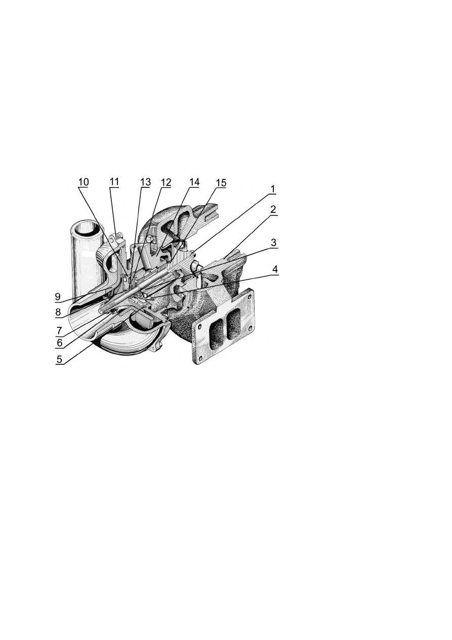
 Turbocharger, according to Fig.10, is made on the principle: radial centrifugal turbine 
and centrifugal single-stage compressor with overhanging location of wheels relative to 
the supports.  
The rotor speed, the charge air flow and pressure depend on the engine operation mode. 


1  –  turbine wheel with shaft; 2 –  turbine housing; 3 -  monobush; 4 –  oil deflector; 
 5 – eccentric ring; 6 – compressor wheel; 7 – special nut; 8, 15 –sealing rings; 9 - diffuser; 10 - cover; 
11 – compressor housing; 12 – thrust bearing; 13 – space bush; 14 – middle housing (bearings housing). 

 
Fig. 17

а – Uncontrolable turbocharger  

 
The housing of turbine 2 is made of high-strength cast iron. The turbine flow-through 
part for exhaust gases is fromed by the turbine housing and the turbine wheel.   
Compressor housing 11 is made of alluminium alloy, its flow-through part is formed by 
the compressor housing and compressor wheel.  
The turbine and compressor housings are fixed to bearings housing 14 made of high-
strength cast iron. 
  
Turbine whell 1 is cast of heat-proof alloy and welded to the rotor shaft.  
Compressor wheel 6 is cast of alluminium alloy and is fixed to the rotor shaft with a spe-
cial nut.  
The rotor shaft rotates in a radial bearing made as a floating non-rotating monobush 3. 
The monobush is secured in the bearings housing by a fixer. The rotor axial motion is 
taken by thrust bearing 12.  


The turbocharger bearings are lubricated and cooled by oil delivered through the   pipe-
line from a full-flow oil filter. Both the radial and the thrust bearings provide additional 
centrifugal oil cleaning. Oil then is drained into the oil sump through an oil diversion 
pipe.   
 On the compressor and turbine side there are gas-oil sealimgs – spring sealing rings 8 
and 15, installed in the rotor groove. For efficiency raising, on the compressor side there 
os an oil deflector and a screen on the turbine side. 
Installed in diesel engine D-260.4S3

А is a controllable turbocharger (Fig. 17b). 


1 – rotor; 2 – turbine housing; 3 – bearing housing; 4 – compressor housing; 5 – actuating mechanism; 6 
- actuating mechanism bracket; 7 – air duct. 
 

Fig. 17b - Controlable turbocharger. 
 
Supercharging is regulated by diversion of a portion of exhaust gases past the turbine 
wheel at certain supercharge pressure values.  
By design, turbocharger, as shown on Fig.17b consists of the following basic units: rotor 
1, turbine housing 2, bearing housing 3, compressor housing 4, actuating mechanism 5, 
actuating mechanism bracket 6, air duct 7. 
The rotor includes a shaft welded to the turbine wheel and the compressor wheel, oil 
sealing space bush, two washers and two sealing rings. The rotor rotates in the radial 
bearing, mounted in the bearing housing. The rotor axial motion is taken by the thrust 
bearing.  
Incorporated in the controllable turbocharger housing is a bypass valve. With a control-
lable rod, the bypass valve lever is coupled with the actuating mechanism, in its turn 
linked with the compressoe outlet by the air duct.    
 The regulator setting to a ceratian pressure is done by adjusting the rod length.   
The turbocharger actuating mechanism rod length within the operation period is not 
permissible.  
The turbocharger bearings are lubricated and cooled by the oil coming through the die-
sel engine lubrication system pipeline. The oil is drained from the turbocharger into the 
engine oil sump.  
The turbocharger disassembling and repair during the engine use is not permissible. 
When out of use, it should be done at a specialized repair shop.   

1.2.2.9  Starting device 


Diesel engines tarting device is an electric starter motor with rated voltage of 24V.    
Starter motor is a direct current electric motor with mixed excitation and a drive mecha-
nism. 
To facilitate startup at low ambient temperatures, all the engines are equipped with glow 
plugs with rated voltage of 23V and have heat carrier inlet and outlet locations for en-
gine prestart heating systems, installed by customer in a tractor/ agricultural machine.     
A tractor/ agricultural machine electric circuit diagram must include starter motor block-
ing after engine startup – starter motor switch-off upon the crankshaft speed reaching 
900 min-1  to 1000 min-1 and inability to switch it on with the engine running. 
 1.2.2.10  Alternator and its drive 
 
Installed in diesel engines are alternators serving as electric equipment  power sources.  
Alternators have terminals for connection to circuits: «+» («

В») – load and accumulator 

battery; «

Д» («D») – starter motor blocking relay; «~» («W») - tachometer. 

Alternator is used for accumulator battery recharging and direct current supply to elec-
tricity consumers installed in a tractor/ agricultural machine.   
 Alternator is driven by a V-belt on the crankshaft pulley. 
  

1.2.2.11  Compressor and its drive 
 
To drive pneumatic trailer brakes and tire inflation, diesel engines installed in trac-
tors,combine harvesters, machine are equipped with a piston single stage compressor 
(Table 6). 
 Compressor  

А29.05.000БЗА is mounted on the distribution cover flange and is driven 

by the compressor and the distribution mechanism fuel pump drive gear.   
With a diesel engine being used in agricultural work not requiring compressed air power, 
compressor 

А29.05.000БЗА must be switched off.  It is not allowed to switch the com-

pressor on with the engine running. Compressor 

А29.05.000БЗА is air cooled.


1.2.2.12  Gear pump and its drive 
 
Hydroficated tractor or other vehicle control systems imply installation of 

НШ 14-3Л or 

НШ 16-3Л, or НШ-10 gear pump  in diesel engines. 
The gear pump is rotated by the engine distribution gears. 
  
1.2.2.13  Clutch 
Clutch is designed for torque transfer from the engine crankshaft to transmission and for 
short time diesel emgine disconnection from transmission, while the engine is running, to 
ensure bumpless shifting the gears and smooth vehicle pulling away. 
 Installed in diesel engines are friction type, dry, single disc or double-disk permanently-
closed clutches as shown on Table 6.  
  

1.2.3 Diesel engine labelling and sealing 
Labelling and sealing of diesel engines manufactured by “MMP” is done according to 
the current manufacturer design documentation. Labelling of diesel engines big size parts 
– according to supplier companies’ design documentation. 
  

2 APPROPRIATE USE 

  2.1  Operating restrictions 

For long time and troubleless diesel engine operation, follow the basic conditions below: 
- For proper“COMMON RAIL” electronic control system functionEng, the electronic 
Control Unit software must comply with the application of tractors/ agricultural ma-
chines where the engines are installed; 
- Before putting a newly manufactured engine into operation under load, run it in accord-
ing to article 2.3.4;  
- At the beginning of a working shift, before the engine start check the oil level in the en-
gine oil sump and that of the cooling liquid in the radiator or the expansion tank. 
- After the engine start, before loading the engine, let it run for 2-3 minutes, first at the 
minimal idle speed with gradual increase to not more than 1600 min

-1

. Full load of a cool 

engine is not allowed (the permissible oil pressure value for a not warmed up engine – 
not more than 0,8 MPa); 
- At emergency engine idling (warming up, air pumping to the braking system cylinders 
etc.) it is necessary to keep the engine crabkshaft speed at not less than 1000 – 1200 min

1

- During the engine running watch the controls indications:  
- Engine operation with the oil pressure in the main oil duct lower than 0,1MPa is not 
permissible;  

The cooling liquid heating over 100°С is not permissible;  

- In the event of the oil pressure or the cooling liquid temperature exceeding the said val-
ues the engine must be stopped; 


Content   ..  8  9  10  11   ..