DDFP SERIES ENGINES FOR FIRE PUMP APPLICATIONS MP-4. Manual - part 10


  Index      Engines     DDFP SERIES ENGINES FOR FIRE PUMP APPLICATIONS MP-4 - service manual


Search            


Content   ..  8  9  10  11   ..


DDFP SERIES ENGINES FOR FIRE PUMP APPLICATIONS MP-4. Manual - part 10


DDFP

SECTION 3.5

Page 32

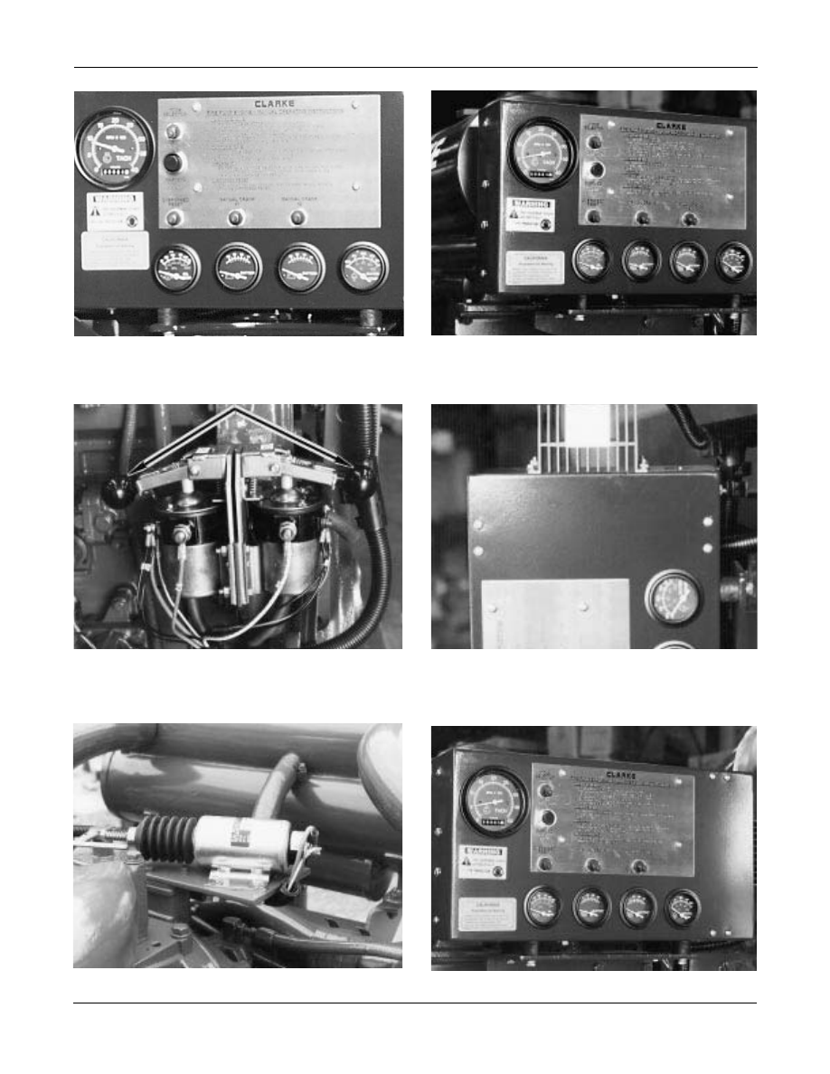
Fig. 2 - Emergency Operating Instructions

Fig. 3 - Automatic - Manual Mode Selector

Fig. 7 - Instrument Panel

Fig. 4 - Manual Contactors

Fig. 5 - DC Junction Box

Fig. 6 - Governor Solenoid

SECTION 3.5

DDFP

Page 33

MANUAL START INSTRUCTIONS

The engine can be operated without using the engine con-

troller. Use the following procedure when manual starting is

required. Refer to Fig. 2, Page 32.

To Start Engine

1. OPEN COOLING SYSTEM MANU

AL BYP ASS

VALVE. Located on the cooling loop, Fig. 8, Page 29.

2. POSITION 

MODE

SELECTOR IN 

MANUAL

RUN.

Fig. 3, Page 32.

3. POSITION

BATTERY SELECTOR

SWITCH T O

BATT. #1.

4. PULL AND HOLD MANUAL CONTACTOR  #1, Fig.

4, Page 32 UNTIL ENGINE ST

ARTS, RELEASE

AFTER 5 SECONDS. IF UNIT F AILS  TO ST ART,

POSITION

BATTERY SELECTOR

TO B   #2 USE

STARTER CONTACTOR #2, AND REPEAT STEP.

To Stop Engine

1. RETURN

MODE SELECTOR

TO

AUTOMATIC,

AND

MANUAL STOP,

ENGINE WILL STOP.

2. CLOSE COOLING SYSTEM MANU AL BY -PASS

VALVE.

IMPORTANT:

DO NOT

LEAVE THE 

MODE SELECTOR

SWITCH

IN THE 

MANUAL RUN

POSITION DURING 

AUTO-

MATIC

OPERATION. (THE CONTROLLER WILL BE

UNABLE TO STOP THE ENGINE AND 

OVERHEAT

DAMAGE WILL RESULT

)

DO NOT

POSITION THE 

BATTERY SELECTOR

SWITCH  TO  A DEFECTIVE B ATTERY  WHILE IN

THE

MANUAL MODE.

GOVERNOR OPERATING SOLENOID

The DC go vernor solenoid, Fig. 6, Page 32, is an essential

item for the operation of this fire pump system. Upon receiv-

ing a signal, the solenoid is energized to move the governor

into the run position.

This solenoid remains ener gized during engine operation.

To stop the engine, the solenoid de-energizes and the gover-

nor returns to the "no fuel" position by spring action.

INSTRUMENTATION

Figure 7, Page 32 sho ws the instrumentation panel which

contains the follo wing gauges: tachometer with inte gral

hourmeter (1), engine oil pressure (P.S.I.) (2), battery volt-

meter (3), engine coolant temperature (°F) (4), battery isola-

tor (5). Engine overspeed switch is mounted to rear of gauge

panel Figure 8.

Tachometer and Integral Hourmeter - 

This meter re-

ceives its signal from the o verspeed switch to allo w operator

to read engine RPM, in addition the hour meter records a

cumulative total of engine operating hours.

Oil Pressure -

This mechanical gauge gives engine oil pres-

sure readings in english and metr ic units (PSI & kP A). Con-

nection location to the engine will vary per engine model.

Engine Coolant Temperature -

This temperature gauge

indicates the engines coolant outlet temper ature in de grees

fahrenheit (°F) and centrigrade (°C).

Voltmeter -

This gauge identifies the voltage level of the bat-

tery according to the position of the ba ttery selector switch.

SPEED SWITCH

After the engine has started and reached 1000 RPM,the speed

switch signals the contr oller to terminate the starter cranking

action. An overrunning clutch is included on the star ter drive

to prevent damage from overspeeding when the unit starts.

NOTE:

When starting unit with man ual contactor s, re-

lease contactor handle as soon as eng ine starts.

In the event of an engine o verspeed the speed s witch signals

the AEC and ef fects an engine shutdo wn.  A MANU AL

RESET button is included on the switch and must be "pushed

in" to reset the speed s witch after unit has shutdo wn from an

Fig. 8 - Overspeed Reset

DDFP

SECTION 3.5

Page 34

overspeed condition.  The reset b utton is sho wn in Fig. 8,

Page 33.

NOTE:

Engine will not r estart after an o verspeed shut-

down, UNTIL OPERA TOR RESETS  THIS

BUTTON. DO NO T ATTEMPT TO RESTART

ENGINE UNTIL VERIFICATION HAS BEEN

MADE  AS  TO  THE REASON FOR O VER-

SPEED.

A magnetic-pic kup, mounted in the f lywheel housing pr o-

vides the input signal f or the o verspeed switch. See Fig. 9,

pickup mounting. The magnetic-pickup senses the speed of

the engine by counting the f lywheel ring gear teeth per sec -

ond. There should be a 0.03" (.762 MM) air gap between the

top of the r ing gear and the ma gnetic pickup.  With a gear

tooth aligned with the center of the ma gnetic pic kup hole,

thread the pickup in until it touc hes the gear tooth and then

back it out

1/

2

turn. Tighten jam nut while holding the

pickup in position. Reconnect to wiring harness.

WARNING:

All current production DDFP engines use

electronic o verspeed protection controls. Due

to the delicate nature of this devise, it is manda-

tory that diagnostic probing of the circuitry be

done with the electrical po wer of f. Probing

with any device that causes amperage to exceed

ratings will damage this control.  This warning

applies to terminals of the o verspeed switch

and inside the junction box. This type of failure

is not warrantable.

BATTERY CHARGING ALTERNATOR

This belt dri ven engine alternator pro vides po wer to

recharge both battery banks directly through the battery iso-

lator. The battery isolator pre vents backfeed from one bat-

tery bank to the other. The alternator is mounted at the front

of the engine as shown in Fig. 10. The alternator is belt dri-

ven from the crankshaft or camshaft pulle y. 

STARTER

Fig. 9 - Magnetic Pickup

Fig. 10 - Typical Alternator

The DC electric starting motor pro vides cranking ef fort to

initiate an engine start. Located on the flywheel housing of

the engine, it is shown in Fig. 11, Page 35.

For automatic operation or test operation, the signal for start

initiation comes from the controller. For manual start at the

engine, activating either contactor #1 or #2 should start the

engine. Re view the MANU AL OPERATING INSTR UC-

TIONS for additional details on Page 33.

SECTION 3.5

DDFP

Page 35

ENGINE HEATER

The engine heaters are required by NFP A-20 specification

and should maintain the engine coolant at 120° F (54° C).

Check the engine temperature gauge for corresponding per-

formance. See Page 39 for AC wiring, diagram.

A. Condition: - Unit holds minimum 120° F.

Service: - No Service Required

B. Condition: - Unit holds less than 120 F, but above room

temperature.

Service: - One heater element may not be functioning.

Check wiring or replace defective element.

C. Condition: - Engine coolant at room temperature

Service: - 1. Check 120V-AC POWER SOURCE.

2. Check wiring connections.

3. Check thermostat function, see Fig. 1.

4. Replace element if defective.

CAUTION:

DISCONNECT AC POWER TO HEATER

SYSTEM BEFORE DRAINING ENGINE

COOLANT.

through a 6 minute c ycle (15 seconds cranking and 15 sec-

onds rest, in 12 consecuti ve cycles). Battery recommenda-

tions are shown for each engine on the respecti ve model in

Section 5.

BATTERY CABLES

Customer Supplied Battery Cables should be sized as rec-

ommended in Section 5.

WIRING DIAGRAMS (DC)

Wiring diagrams represented in this section, Figs. 13 and 14

have two basic differences. Other than optional voltage dif-

ferences of 12V or 24V, the primary difference is the engine

instrumentation. Certain DDFP models use mechanical type

others use electric instruments.

Should it be necessary to diagnose a wiring problem,

see

below for identifying which diagram to use.

Fig. 13 Drawing #CO7264 includes  Amp Meter with Me-

chanical instruments.

Fig. 14 Drawing #CO7484 includes Volt Meter with Elec-

trical instruments.

Verify which type your engine has before proceeding.

WIRING DIAGRAMS (AC)

The diagram represented in Fig. 15 identifies the AC wiring

requirements necessary for the jack et water heater. An op-

tional lube oil heater is included.

These heaters have optional voltages, depending on installa-

tion requirements. Each heater is controlled by a thermostat

mounted in the engine heater.

Two alarm switches pro vide condition signal to the engine

controller. First, a coolant temperature switch is pro vided

and mounts on front of right c

ylinder head.  When the

coolant temperature reaches 205° F (96° C),the switch clos-

es and causes a light to burn and sounds an alarm bell on the

engine controller. Second, an oil pressure switch is pro vid-

ed for low oil pressure signal. Should oil pressure drop to or

below 20 P.S.I. (138 kPA) the NC switches closes and caus-

es a light to b urn and sounds an alarm bell on the engineer

controller.

Neither a high coolant temperature or a low oil pressure sig-

nal will cause the controller to stop the engine.  The alarm

bell can be silenced at the controller and an in vestigation

made to determine cause of the signal.  The controller lights

will continue to burn until the fault is corrected.

BATTERIES

NFPA-20 requires that fire pump systems include two inde-

pendent battery units. Each battery bank must ha ve capaci-

ty, at 40° F (4.5° C), sufficient to maintain cranking speed

MAINTENANCE AND SERVICE PROCEDURES

Fig. 11 - Typical Starter


Content   ..  8  9  10  11   ..