Kawasaki Diesel MULE 4010 TRANS 4x4 (KAF950G9). Manual - part 129
 

  Index      Engines     Kawasaki Diesel MULE 4010 TRANS 4x4 (KAF950G9) - service manual


Search            


Content   ..  127  128  129  130   ..


Kawasaki Diesel MULE 4010 TRANS 4x4 (KAF950G9). Manual - part 129


17-62 ELECTRICAL SYSTEM

Switches and Sensors

Brake Light Switch Inspection

•

Refer to the Brake Light Switch Inspection in the Periodic
Maintenance chapter.

Radiator Fan Switch Inspection

•

Remove the radiator fan switch (see Radiator Fan Switch
Removal in the Cooling System chapter).

•

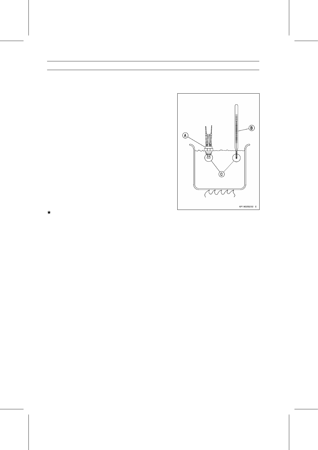
Suspend the fan switch [A] in a container of coolant so that
the temperature sensing projection and threaded portion
are submerged.

•

Suspend an accurate thermometer [B] in the coolant, so
that the sensitive portions [C] are located in almost the
same depth.

NOTE

○

The switch and thermometer must not touch the con-
tainer sides or bottom.

•

Place the container over a source of heat and gradu-
ally raise the temperature of the coolant while stirring the
coolant gently.

•

Using the hand tester, measure the internal resistance
of the switch across the terminals at the temperatures
shown in the table.

Special Tool - Hand Tester: 57001-1394

If the hand tester does not show the specified values, re-
place the switch.

Radiator Fan Switch Resistance

Rising Temperature:

From OFF to ON at 86

∼ 90°C (187 ∼ 194°F)

Falling Temperature:

From ON to OFF at 81

∼ 85°C (178 ∼ 185°F)

ON: Less than 0.5 Ω
OFF: More than 1 MΩ

ELECTRICAL SYSTEM 17-63

Switches and Sensors

Coolant Temperature Switch Inspection

•

Remove the coolant temperature switch (see Coolant
Temperature Switch Removal in the Cooling System
chapter).

•

Suspend the switch [A] in a container of coolant so that
the temperature sensing projection and threaded portion
are submerged.

•

Suspend an accurate thermometer [B] in the coolant, so
that the sensitive portions [C] are located in almost in the
same depth.

NOTE

○

The switch and thermometer must not touch the con-
tainer sides or bottom.

•

Place the container over a source of heat and gradu-
ally raise the temperature of the coolant while stirring the
coolant gently.

•

Using the hand tester, measure the internal resistance
of the switch across the connector and the body at the
temperatures shown in the table.

Special Tool - Hand Tester: 57001-1394

If the hand tester does not show the specified values, re-
place the switch.

Coolant Temperature Switch Resistance

Rising Temperature:

From OFF to ON at 112

∼ 118°C (234 ∼ 244°F)

Falling Temperature:

From ON to OFF within 10°C (50°F)
of “ON” temperature

ON: Less than 0.5 Ω
OFF: More than 1 MΩ

17-64 ELECTRICAL SYSTEM

Switches and Sensors

Switch Inspection

•

Using a hand tester, check to see that only the con-
nections shown in the table have continuity (about zero
ohms).

Special Tool - Hand Tester: 57001-1394

○

For the main switch, light switch, brake light switch, park-
ing brake light switch, and neutral switch, refer to the ta-
bles in the Wiring Diagram.
If the switch has an open or short, repair it or replace it
with a new one.

Horn Switch Connections

Oil Pressure Switch Connections*

*: Engine lubrication system is in good condition.

Reverse Light Switch Connections (EUR Model)

Speed Sensor Removal

NOTICE

Never drop the speed sensor, especially on a hard
surface. Such a shock to the sensor can damage it.

•

Drain the transmission oil (see Transmission Oil Change
in the Periodic Maintenance chapter).

•

Disconnect the speed sensor lead connector [A].

•

Remove:

Bolt [B]
Speed Sensor [C]

ELECTRICAL SYSTEM 17-65

Switches and Sensors

Speed Sensor Installation

•

Replace the O-ring [A] with a new one.

•

Apply transmission oil to the O-ring.

•

Tighten

Torque - Speed Senor Bolt: 8.8 N·m (0.90 kgf·m, 78 in·lb)

Speed Sensor Inspection

•

Remove the speed sensor (see Speed Sensor Removal).

•

Connect the speed sensor connector [A] with the battery
[B], 10 kΩ resistor [C] and hand tester [D] as shown in the
figure.

•

Set the tester to the DC 25 V range.

Special Tool - Hand Tester: 57001-1394

•

Trace [A] each side of the speed sensor surface with the
screwdriver.

○

Then the tester indicator should flick [B].
If the tester indicator does not flick, replace the speed
sensor.


Content   ..  127  128  129  130   ..