Kawasaki Diesel MULE 4010 TRANS 4x4 (KAF950G9). Manual - part 122
 

  Index      Engines     Kawasaki Diesel MULE 4010 TRANS 4x4 (KAF950G9) - service manual


Search            


Content   ..  120  121  122  123   ..


Kawasaki Diesel MULE 4010 TRANS 4x4 (KAF950G9). Manual - part 122


17-34 ELECTRICAL SYSTEM

Alternator

•

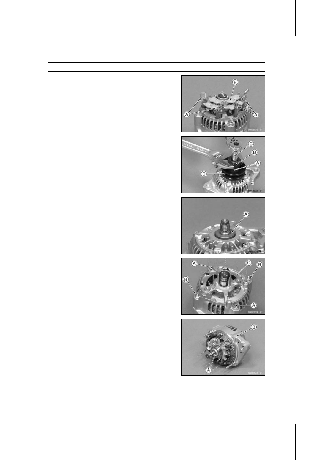
Straighten the stator coil wires [A].

•

Remove the rectifier [B].

•

Use the following, loosen the pulley locknut [A].

Socket Wrench [B] (Special Tool: 57001-1236)
Deep Socket Wrench [C]

Special Tool - Socket Wrench, Hex 22: 57001-1236

•

Remove:

Pulley Locknut
Pulley [D]

•

Remove the collar [A].

•

Remove:

Housing Cover Mounting Bolts [A] and Nuts [B]
Housing Cover [C]

•

Remove:

Rotor [A]
Alternator Housing [B]

ELECTRICAL SYSTEM 17-35

Alternator

•

Remove:

Bearing Holder [A]
Ball Bearing [B]

○

To remove the ball bearing [A], use a suitable puller.

Alternator Assembly

•

Press the bearing and bearing holder onto the rotor shaft.

•

Straighten the stator coil wires.

•

Install:

Housing Cover [A]
Housing Cover Mounting Bolts [B] and Nuts [C]

•

Install the rectifier [A].

•

Bend the stator coil wire ends [B] around the screw holes.

•

Tighten the rectifier screws.

•

Install:

Regulator
Brush Holder
End Cover
Insulator
Terminal Nut

17-36 ELECTRICAL SYSTEM

Alternator

•

Install:

Collar
Pulley [A]

•

Use the following, tighten the locknut.

Socket Wrench [B] (Special Tool: 57001-1236)
Deep Socket Wrench [C]

Special Tool - Socket Wrench, Hex 22: 57001-1236

Torque - Alternator Pulley Locknut: 11 N·m (1.1 kgf·m, 97

in·lb)

Alternator Operational Inspection

•

Check the battery condition.

Conventional Type Battery (see Charging Condition
Inspection (Conventional Type Battery) in the Periodic
Maintenance chapter)
Sealed Type Battery (see Charging Condition Inspection
(Sealed Type Battery))

NOTE

○

Always check the battery condition before condemning
the alternator. The battery must be fully charged in or-
der to conduct accurate alternator inspection.

•

Check the wiring (see Wiring Inspection).

•

Warm up the engine to bring the components up to their
normal operating temperatures.

•

Stop the engine.

•

Remove the 30 A main fuse (see Fuse Removal).

•

Connect the hand tester [A] (range DC 25 V) and ammeter
[B] (range DC 40 A, after the engine start) as shown in the
figure.

Battery [C]
50 A Fuse [D]
Alternator [E]
Load [F]

•

Measure the alternator output voltage and amperage at 2
000 rpm with the light switch turned OFF.

Alternator Output Voltage

Standard:

13.3

∼ 14.8 V at 25°C (77°F)

Alternator Output Amperage (no load)

Standard:

10 A or less

•

Stop the engine.

•

Install the 30 A main fuse (see Fuse Installation).

•

Measure the alternator output voltage and amperage at 2
000 rpm with the light switch turned ON.

Alternator Output Voltage

Standard:

13.3

∼ 14.8 V at 25°C (77°F)

Alternator Output Amperage (load)

Standard:

20 A or more

If the readings are not within the specified range, check
the alternator.

ELECTRICAL SYSTEM 17-37

Alternator

Stator Coil Inspection

•

Connect the hand tester (× 1 Ω range) between the coil
wires and read the tester.

Special Tool - Hand Tester: 57001-1394

If the tester does not read as specified, replace the alter-
nator frame.

Stator Coil Resistance: 0.2 Ω or less

•

Using the highest hand tester range, measure the resis-
tance between the stator coil core and each of the coil
windings.
If there is any reading at all, the stator coil winding has a
short and the alternator housing must be replaced.

Rotor Coil Inspection

•

Connect the hand tester (× 1 Ω range) between the slip
rings [A] and read the tester.

Special Tool - Hand Tester: 57001-1394

If the tester does not read as specified, replace the rotor
[B].

Rotor Coil Resistance: 2.8

∼ 3.0 Ω

•

Using the highest tester range, measure the resistance
between the rotor shaft and each of the slip rings.
If there is any reading at all, the rotor coil has a short and
must be replaced.

Slip Ring Cleaning

•

Visually inspect the slip ring for dirt or pitting.
If necessary, smooth the slip ring with No. 300

∼ No. 500

emery cloth.

Slip Ring Diameter

•

Measure the diameter of the slip rings.
If the measurement is less than the service limit, replace
the rotor [A].

Slip Ring Diameter

Standard:

14.4 mm (0.57 in.)

Service Limit:

14.0 mm (0.55 in.)

Carbon Brush Length

•

Measure the length [A] that both carbon brushes that stick
out of the holder.
If either one is worn down to less than the service limit,
replace it.

Carbon Brush Length (Projected Portion)

Standard:

10.5 mm (0.41 in.)

Service Limit:

8.4 mm (0.33 in.)


Content   ..  120  121  122  123   ..