Kawasaki Diesel MULE 4010 TRANS 4x4 (KAF950G9). Manual - part 103
 

  Index      Engines     Kawasaki Diesel MULE 4010 TRANS 4x4 (KAF950G9) - service manual


Search            


Content   ..  101  102  103  104   ..


Kawasaki Diesel MULE 4010 TRANS 4x4 (KAF950G9). Manual - part 103


15-52 STEERING

EPS (Electric Power Steering) System

•

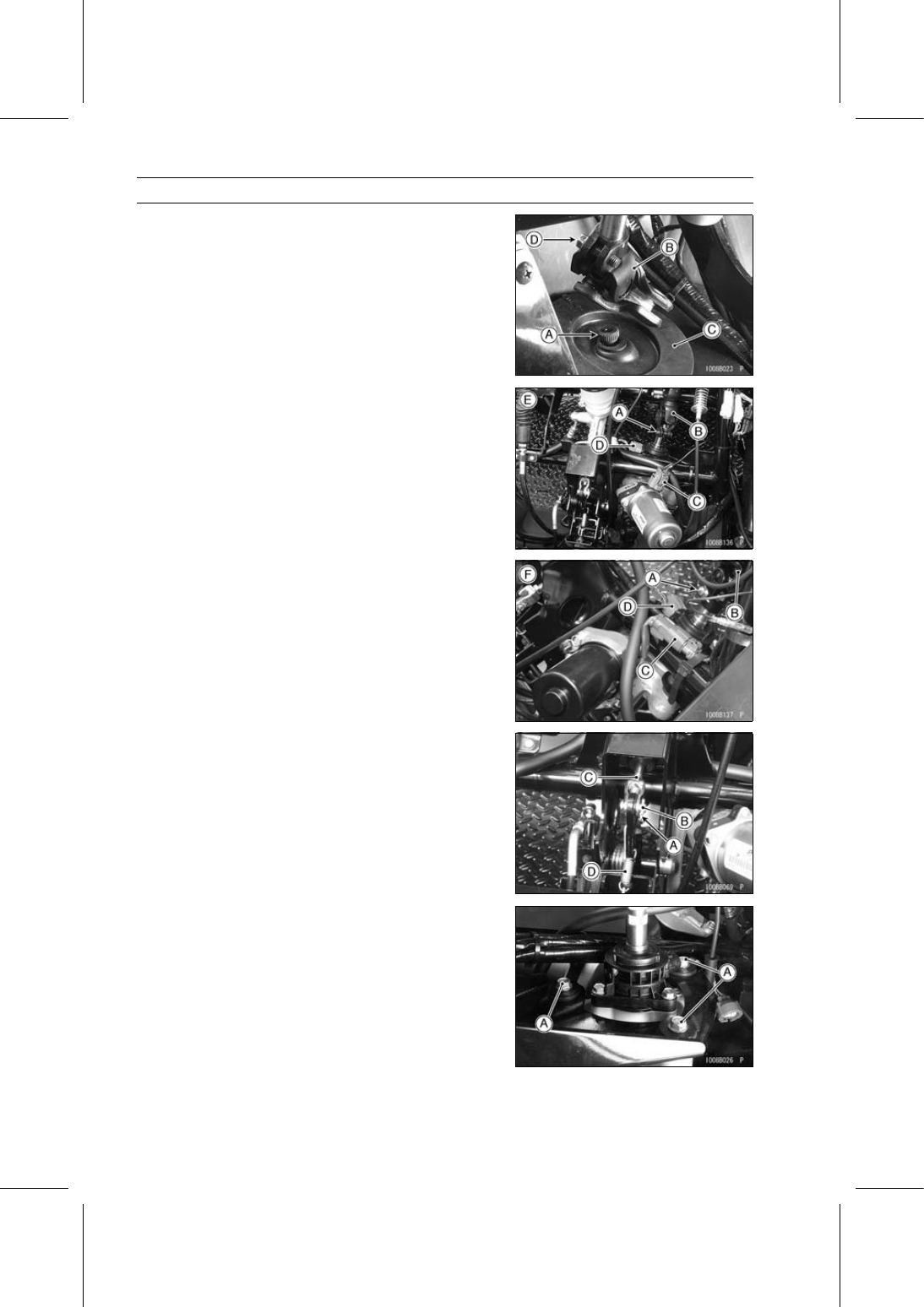
Move the steering gear assembly, and pull off the shaft
[A] from the lower universal joint [B].

○

Lower the steering gear assembly, and then pull it for-
ward.

•

Remove:

Rubber Boot [C]
Universal Joint Clamp Bolt [D]
Lower Universal Joint

•

Remove:

Steering Shaft (see Steering Wheel and Steering Shaft
Removal)
Universal Joint Clamp Bolt [A]
Upper Universal Joint [B]

•

Disconnect:

EPS Motor Connector [C]
Torque Sensor Connector [D]
[E] KAF950G9

∼ GC/HA

[F] KAF950GD

•

Remove:

Cotter Pin [A]
Pin [B]
Push Rod [C]
Spring [D]

•

Remove the EPS unit mounting bolts [A].

STEERING 15-53

EPS (Electric Power Steering) System

•

Remove the EPS unit [A] downward while pushing down
the brake pedal [B].

○

Insert the lower shaft to the hole of the under cover and
avoid the upper shaft from the frame.

NOTICE

The EPS unit [A] has been adjusted and set with
precision at the factory. Do not try to disassemble
and repair the EPS unit.

[B] KAF950G9

∼ GC/HA

[C] KAF950GD

EPS Unit Installation

•

Check that the rubber dampers [A] and upper and lower
collars [B] are in place on the frame.
If the rubber dampers are damaged or deteriorated, re-
place them.

○

When installing the rubber dampers, note the following.

○

Install the rubber dampers so that the thin thickness side
faces up.

○

Do not apply a rubber lubricant.

•

Install the EPS unit so that the EPS torque sensor [A]
faces upside.

•

Install the EPS unit mounting bolts [B] and tighten them
temporary.

•

Install the lower universal joint [C] to the shaft of the EPS
unit.

•

Install the universal joint clamp bolt [D] while aligning the
notch on the shaft of the EPS unit with the clamp bolt hole
on the lower universal joint, and tighten it temporary.

[E] KAF950G9

∼ GC/HA

[F] KAF950GD

15-54 STEERING

EPS (Electric Power Steering) System

•

Install the rubber boot [A] on the shaft [B] of the steering
gear assembly temporary.

•

Install the shaft of the steering gear assembly to the lower
universal joint [C].

•

Install the universal joint clamp bolt [D] while aligning the
notch on the shaft of the steering gear assembly with the
clamp bolt hole on the lower universal joint, and tighten it
temporary.

•

Install:

Rubber dampers [E]
Brackets [F]

•

Apply non-permanent locking agent to the steering gear
assembly bracket bolts [G] and tighten them evenly.

Torque - Steering Gear Assembly Bracket Bolts: 52 N·m

(5.3 kgf·m, 38 ft·lb)

•

Tighten the EPS unit mounting bolts to the specified
torque.

Torque - EPS Unit Mounting Bolts: 20 N·m (2.0 kgf·m, 15

ft·lb)

[H] KAF950G9

∼ GC/HA

[I] KAF950GD

•

Install the rubber boot [A] so that the mark (F, Arrow) [B]
faces forward.

•

Install the upper universal joint [A] to the shaft of the EPS
unit [B].

•

Install the universal joint clamp bolt (lower) [C] while align-
ing the notch on the shaft of the EPS unit with the clamp
bolt hole on the upper universal joint, and tighten it tem-
porary.

•

Install the steering shaft [D] to the upper universal joint.

•

Install the universal joint clamp bolt (upper) [E] while align-
ing the notch on the steering shaft with the clamp bolt hole
on the upper universal joint, and tighten it temporary.

•

Install the steering shaft mounting bolts [F], washers [G]
and nuts [H].

•

Tighten all the universal joint clamp bolts to the specified
torque.

Torque - Universal Joint Clamp Bolts: 20 N·m (2.0 kgf·m,

15 ft·lb)

•

Install the washer [I] (KAF950GD).

[J] KAF950G9

∼ GC/HA

STEERING 15-55

EPS (Electric Power Steering) System

•

Mount the steering wheel on the steering shaft temporar-
ily.

•

Adjust the following items.

Steering Wheel Position (see Steering Wheel Position
Adjustment)
Steering Wheel Centering (see Steering Wheel Center-
ing)

•

Install the removed parts (see appropriate chapters).

•

Be sure to register the EPS neutral position (see EPS
Neutral Position Registration).

Speed Sensor Removal/Installation

•

Refer to the Speed Sensor Removal/Installation in the
Electrical System chapter.

Speed Sensor Inspection

•

Refer to the Speed Sensor Inspection in the Electrical
System chapter.
If the speed sensor is normal, check the wiring for conti-
nuity (Refer to the next wiring diagram.).

Speed Sensor Circuit

1. EPS ECU
2. Speed Sensor
3. Oil Pressure Warning Indicator Light
4. Main Switch

5. Battery 12 V 52 Ah
6. Main Fuse 30 A
7. Fuse Box 2
8. Oil Pressure Switch


Content   ..  101  102  103  104   ..