Kawasaki Diesel MULE 4010 TRANS 4x4 (KAF950G9). Manual - part 77
 

  Index      Engines     Kawasaki Diesel MULE 4010 TRANS 4x4 (KAF950G9) - service manual


Search            


Content   ..  75  76  77  78   ..


Kawasaki Diesel MULE 4010 TRANS 4x4 (KAF950G9). Manual - part 77


12-30 FINAL DRIVE

Propeller Shafts

Propeller Shaft Removal

•

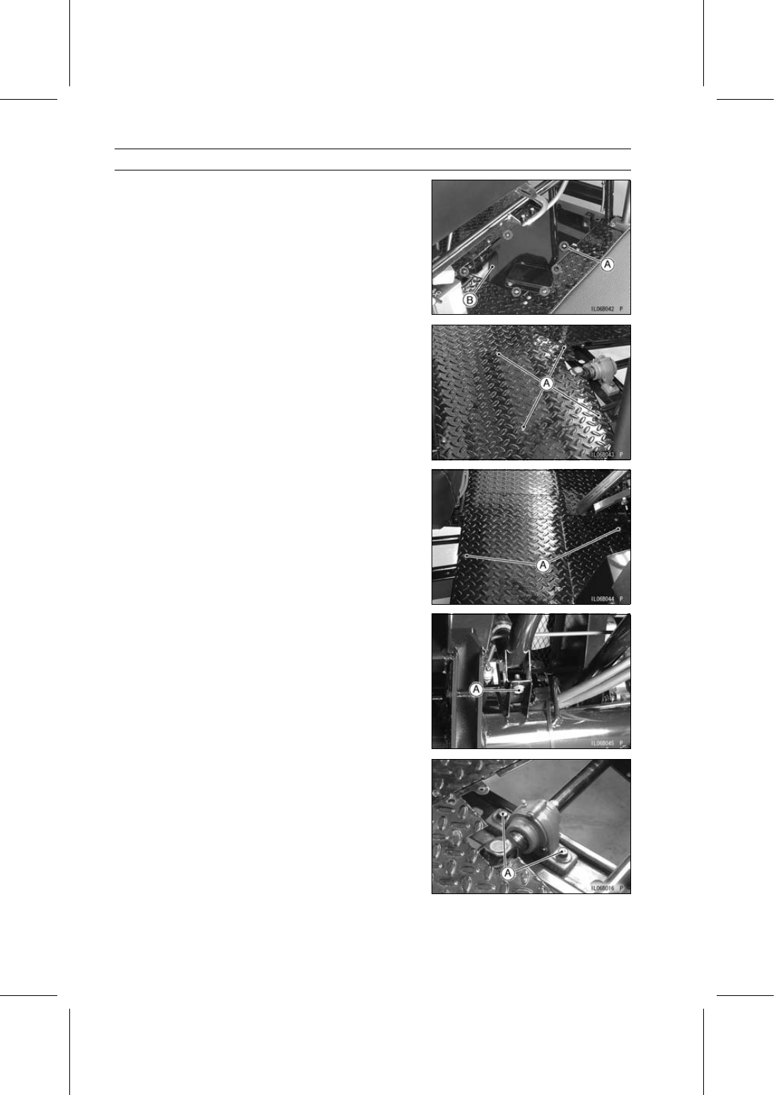
Remove:

Fuel Tank (see Fuel Tank Removal in the Fuel System
chapter)
Tapping Screws [A]
Plate [B]

•

Remove the tapping screws [A].

•

Remove the water pipe bracket bolts [A].

•

Remove the water pipe bracket bolt [A].

•

Remove:

Propeller Shaft Bearing Housing Mounting Bolts [A] and
Nuts
Washers
Collars

FINAL DRIVE 12-31

Propeller Shafts

•

Move the water pipe [A] and the propeller shaft bearing
housing [B] to the outside [C].

•

Remove:

Rear Propeller Shaft [D]
Front Propeller Shaft

Propeller Shaft Installation

•

Wipe the old grease off the splines of the propeller shafts,
and grease to them.

•

Inspect the propeller shafts (see Propeller Shaft Inspec-
tion).

•

Replace the O-ring [A] with a new one.

•

Apply grease to the new O-ring on the front pinion gear.

•

Install the front propeller shaft yoke [B] on the pinion gear.

•

Put the propeller shaft bearing housing [C] at fully outside
position.

•

Install the rear propeller shaft yoke [D] on the rear driven
gear shaft so that the thin side [E] of the propeller shaft
positions to the rearward.

•

Install the rear propeller shaft yoke [F] on the front pro-
peller shaft rear end [G], aligning the yoke angles [H] of
the front and rear propeller shafts.

•

Parallel [I] the propeller shaft bearing housing [J] with the
mounting bracket [K].

○

Make the 3 mm (0.12 in.) clearance [L] between the yoke
[B] of the front propeller shaft and the front pinion gear nut
[M].

•

Replace the propeller shaft bearing housing nuts [Q] with
new ones.

•

Install:

Propeller Shaft Bearing Housing Bolts [N]
Washers [O]
Collars [P]
Nuts

12-32 FINAL DRIVE

Propeller Shafts

Propeller Shaft Bearing Housing Removal

•

Remove:

Front Propeller Shaft (see Propeller Shaft Removal)
Propeller Shaft Bearing Housing Cover Bolts [A] (Both
Sides)
Propeller Shaft Bearing Housing Covers [B] (Both Sides)

•

Wipe off the grease.

•

Remove:

Stop Screws [A]
Front Propeller Shaft [B]
Propeller Shaft Bearing Housing [C]

FINAL DRIVE 12-33

Propeller Shafts

•

Wipe off the grease.

•

Remove the circlip [A].

Special Tool - Outside Circlip Pliers: 57001-144

•

Remove the propeller shaft bearing housing cover [B].

Propeller Shaft Bearing Housing Installation

•

Clean the front propeller shaft by wiping off the used
grease on it.

•

Install:

Propeller Shaft Bearing Housing Cover [A]
New Circlip

Special Tool - Outside Circlip Pliers: 57001-144

•

Insert the front propeller shaft in the propeller shaft bear-
ing housing [B].

•

Tighten:

Torque - Stop Screws: 3.9 N·m (0.40 kgf·m, 35 in·lb)

•

Apply grease about 8 g (0.28 oz) [C] into each cover.

•

Install:

Propeller Shaft Bearing Housing Covers [A]
Propeller Shaft Bearing Housing Cover Bolts [B] (Both
Sides)

•

Tighten:

Torque - Propeller Shaft Bearing Housing Cover Bolts: 3.4

N·m (0.35 kgf·m, 30 in·lb)

Propeller Shaft Inspection

•

Visually inspect the splines of the propeller shafts.
If they are twisted, badly worn, or chipped, replace the
shafts.

•

Check that the universal joint works smoothly without rat-
tling or sticking.
If it does not, the bearings of the joint are damaged. Re-
place the propeller shaft with a new one.


Content   ..  75  76  77  78   ..