Kawasaki Diesel MULE 4010 TRANS 4x4 (KAF950G9). Manual - part 68
 

  Index      Engines     Kawasaki Diesel MULE 4010 TRANS 4x4 (KAF950G9) - service manual


Search            


Content   ..  66  67  68  69   ..


Kawasaki Diesel MULE 4010 TRANS 4x4 (KAF950G9). Manual - part 68


11-4 WHEELS/TIRES

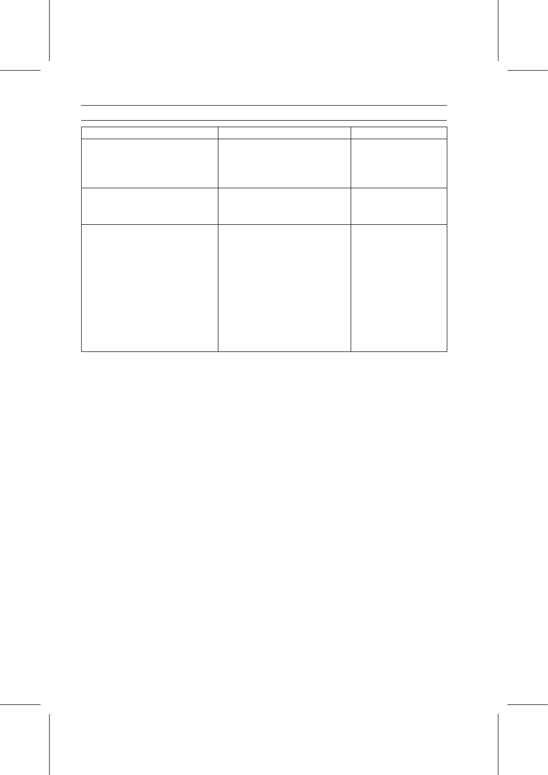
Specifications

Item

Standard

Service Limit

Wheel Alignment

Caster

7.5° (non-adjustable)

– – –

Camber

0.8° (non-adjustable)

– – –

Toe-in

0

∼ 20 mm (0 ∼ 0.79 in.) at 1G

– – –

Wheels (Rims)

Rim Size:

Front and Rear

10 × 8.5 AT

– – –

Tires

Standard Tire:

Front and Rear

23 × 11.00-10
DUNLOP KT869, Tubeless
DURO DK-968, Tubeless

– – –
– – –
– – –

Tire Air Pressure (when Cold):

Front

97 kPa (1.0 kgf/cm², 14 psi)

– – –

Rear

167 kPa (1.7 kgf/cm², 24 psi)

– – –

Maximum Tire Air Pressure (to
seat beads, when cold)

250 kPa (2.5 kgf/cm², 36 psi)

– – –

Tire Tread Depth

13.2 mm (0.52 in.)

3 mm (0.12 in.)

WHEELS/TIRES 11-5

Wheel Alignment

Toe-in is the amount that the front wheels are closer to-

gether in front than at the rear at the axle height. When
there is toe-in, the distance A (rear) is greater than B (front)
as shown in the figure. The purpose of toe-in is to prevent
the front wheels from getting out of parallel at any time, and
to prevent any slipping or scuffing action between the tires
and the ground. If toe-in is incorrect, the front wheels will be
dragged along the ground, scuffing and wearing the tread
knobs.

Caster and camber are built-in and require no adjustment.

A (Rear) - B (Front) = Amount of Toe-in

(Distance A and B are measured at hub height)

Toe-in Adjustment

•

Lift the front wheels off the ground.

•

Apply a heavy coat of chalk near the center of the front
tires.

•

Using a needle nose scriber, make a thin mark near the
center of the chalk coating while turning the wheel.

•

Set the wheels so that the marks on the tires are at the
front side and at the level of the axle height.

•

Ground the front wheels.

•

Set the steering wheel straight ahead.

•

At the level of the axle height, measure the distance be-
tween the scribed lines with a measure.

•

Move the vehicle rearward until the marks on the front
tires are at the rear side and at the same level as the axle.

•

Measure the distance between the scribed lines.

•

Subtract the measurement of the front from the measure-
ment of the rear to get the toe-in.

Toe-in of Front Wheels

Standard: 0

∼ 20 mm (0 ∼ 0.79 in.) at 1G

If the toe-in is not the specified value, perform the follow-
ing procedure.

•

Loosen the locknuts [A] on each tie-rod and turn the ad-
justing rods [B] the same number of turns and the same
direction on both sides to achieve the specified toe-in.

11-6 WHEELS/TIRES

Wheel Alignment

NOTE

○

The toe-in will be near the specified range, if the length
of the tie-rod distance between the dust boot end [A] of
steering gear assembly and the locknut [B] is 43.5 mm
(1.71 in.) [C] on both the left and right tie-rods.

•

Tighten:

Torque - Tie-Rod End Locknuts: 44 N·m (4.5 kgf·m, 32 ft·lb)

•

Check the toe-in again.

•

Test drive the vehicle.

WHEELS/TIRES 11-7

Wheels (Rims)

Wheel Removal

•

Loosen the wheel nuts [A].

○

Do not remove the wheel nuts.

•

Lift the wheel(s) off the ground.

•

Remove:

Wheel Nuts
Wheel(s)

Wheel Installation

•

Position the wheel so that the valve stem [A] is toward the
outside of the vehicle.

•

Tighten:

Torque - Wheel Nuts: 137 N·m (14.0 kgf·m, 101 ft·lb)

○

Tighten the wheel nuts in a criss-cross pattern.

Wheel (Rim) Inspection

•

Examine both sides of the rim for dents [A].
If the rim is dented, replace it.

If the tire is removed, inspect the air sealing surfaces [A]
of the rim for scratches or nicks. Smooth the sealing sur-
faces with fine emery cloth if necessary.

Wheel (Rim) Replacement

•

Remove the wheel (see Wheel Removal).

•

Disassemble the tire from the rim.

•

Remove the valve stem and discard it.

NOTICE

Replace the air valve whenever the tire is replaced.
Do not reuse the air valve.

Plastic Cap [A]
Valve Core [B]
Stem Seal [C]
Valve Stem [D]
Valve Seat [E]
Valve Opened [F]


Content   ..  66  67  68  69   ..