Kawasaki Diesel MULE 4010 TRANS 4x4 (KAF950G9). Manual - part 55
 

  Index      Engines     Kawasaki Diesel MULE 4010 TRANS 4x4 (KAF950G9) - service manual


Search            


Content   ..  53  54  55  56   ..


Kawasaki Diesel MULE 4010 TRANS 4x4 (KAF950G9). Manual - part 55


9-22 CRANKSHAFT/CRANKCASE

Crankshaft and Connecting Rods

•

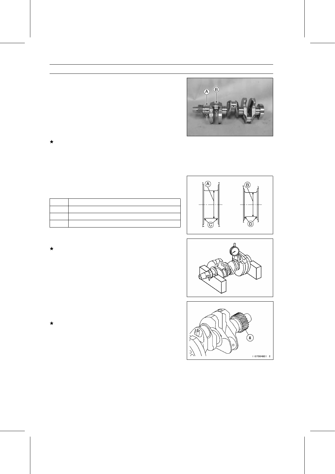
Check the crankshaft main journals and crankpins for
wear and taper.

Crankshaft Main Journal Diameter [A]

Standard:

41.976

∼ 42.000 mm (1.6526 ∼ 1.6535 in.)

Crankshaft Crankpin Diameter [B]

Standard:

36.976

∼ 37.000 mm (1.4557 ∼ 1.4567 in.)

Crankshaft Out of Round and Taper

Service Limit:

0.02 mm (0.0008 in.)

If the crankshaft main journals are not within specification,
the crankshaft may be re-ground and undersize bearing
inserts installed.

Undersize Crankshaft Main Bearing Inserts

0.25 mm (0.0098 in.) Undersize

•

The final finishing dimensions should be as shown in the
table.

Finishing Dimensional Specifications

[A]

41.726

∼ 41.750 mm (1.6428 ∼ 1.6437 in.)

[B]

36.726

∼ 36.750 mm (1.4459 ∼ 1.4468 in.)

[C]

R 2.5 mm (0.0984 in.)

[D]

R 2.1 mm (0.0827 in.)

•

Measure the crankshaft runout at #3 main journal.
If the measurement exceeds the service limit, replace the
crankshaft.

Crankshaft #3 Main Journal Runout

Service Limit:

0.06 mm (0.0024 in.)

•

Visually inspect the crankshaft gear teeth [A].

•

Do the timing gear inspection procedure (see Timing Gear
Inspection).
If the crankshaft gear teeth are damaged or worn, replace
the crankshaft.

CRANKSHAFT/CRANKCASE 9-23

Crankshaft and Connecting Rods

Crankshaft Side Clearance

•

Insert a thickness gauge [A] between the thrust washer
and the crank web at the #3 main journal to determine
clearance.

Crankshaft Side Clearance

Standard:

0.02

∼ 0.24 mm (0.0008 ∼ 0.0094 in.)

Service Limit:

0.30 mm (0.0118 in.)

If the clearance exceeds the service limit, the crankshaft
may be re-ground and oversize thrust washers installed.

Oversize Thrust Washers

0.12 mm (0.0047 in.) Oversize

•

The final finishing dimensions should be as shown in the
table.

Finishing Dimensional Specifications

[A]

22.25

∼ 22.32 mm (0.8760 ∼ 0.8787 in.)

[B]

R 2.5 mm (0.0984 in.)

Crankshaft #3 Main Journal Width

Standard:

22.00

∼ 22.07 mm (0.8661 ∼ 0.8689 in.)

Connecting Rod Big End Bearing Insert/Crankpin

Wear

•

Using plastigage (press gauge) [A], measure the bearing
insert/crankpin clearance.

NOTE

○

Tighten the connecting rod big end nuts to the specified
torque (see Connecting Rod Installation).

○

Do not move the connecting rod and crankshaft during
clearance measurement.

Connecting Rod Big End Bearing Insert/Crankpin
Clearance

Standard:

0.020

∼ 0.044 mm (0.0008 ∼ 0.0017 in.)

Service Limit:

0.07 mm (0.0028 in.)

If the clearance exceeds the service limit, replace the
bearing insert.

•

Repeat the procedure for the other connecting rods.

9-24 CRANKSHAFT/CRANKCASE

Crankshaft and Connecting Rods

Crankshaft Main Bearing Insert/Journal Wear

•

Using plastigage (press gauge) [A], measure the bearing
insert/journal clearance.

NOTE

○

Tighten the crankshaft main bearing cap bolts to the
specified torque (see Crankshaft Installation).

○

Do not turn the crankshaft during clearance measure-
ment.

Crankshaft Main Bearing Insert/Journal Clearance

Standard:

0.020

∼ 0.044 mm (0.0008 ∼ 0.0017 in.)

Service Limit: 0.07 mm (0.0028 in.)

If the clearance exceeds the service limit, replace the
bearing insert.

•

Repeat the procedure for the other main bearings.

CRANKSHAFT/CRANKCASE 9-25

End Plate

End Plate Removal

•

Remove:

Torque Converter Case (see Torque Converter Case Re-
moval in the Converter System chapter)
Stud Bolt [A]

•

Using the flywheel holder [A], hold the flywheel.

Special Tool - Flywheel Holder: 57001-1438

•

Remove:

Flywheel Mounting Bolts [B]
Coupling [C]
Flywheel [D]

•

Remove:

Bolts [A]
Engine Mount Stay [B]
Bolts [C]
Oil Level Gauge Pipe [D]
Bolt [E]

•

Remove:

End Plate Seal Cover [A]
End Plate Bolts [B]
Plate [C]
Starter Motor Mounting Bolts [D]
End Plate [E]

End Plate Installation

•

Remove the old sealant, and clean around the oil seal
retainer and crankshaft end.

•

Apply liquid gasket [A] to the mating surface as shown in
the figure.

Sealant - Three Bond: 1207F

When the starter motor install, refer to the Starter Motor
Installation in the Electrical System chapter.

•

Install the end plate.

•

Tighten:

Torque - End Plate Bolts: 39 N·m (4.0 kgf·m, 29 ft·lb)


Content   ..  53  54  55  56   ..