Kawasaki Diesel MULE 4010 TRANS 4x4 (KAF950G9). Manual - part 52
 

  Index      Engines     Kawasaki Diesel MULE 4010 TRANS 4x4 (KAF950G9) - service manual


Search            


Content   ..  50  51  52  53   ..


Kawasaki Diesel MULE 4010 TRANS 4x4 (KAF950G9). Manual - part 52


9-10 CRANKSHAFT/CRANKCASE

Timing Gear Case

•

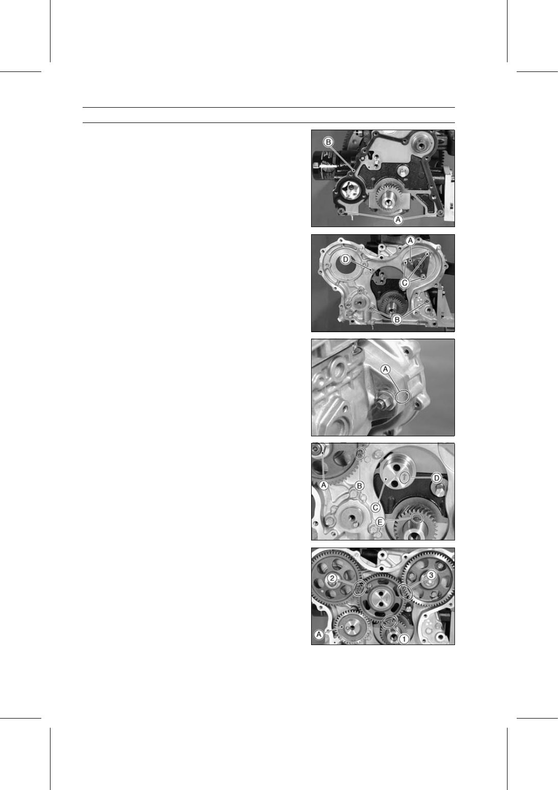
Install:

Dowel Pins [A]
New Timing Gear Case Gasket [B]
Timing Gear Case

○

Rotate the oil pump shaft to engage oil pump rotors.

•

Install the camshaft retainer [A].

•

Tighten:

Torque - Camshaft Retainer Bolts: 7.8 N·m (0.80 kgf·m, 69

in·lb)

Timing Gear Case Bolts: 7.8 N·m (0.80 kgf·m, 69

in·lb)

28 mm (1.10 in.) [B]
18 mm (0.71 in.) [C]
16 mm (0.63 in.) [D]

•

Install the fuel injection pump temporarily.

•

Align the marks [A] on the injection pump and the timing
gear case.

•

Install:

Fuel Injection Pump Drive Gear and Nut [A]
Camshaft Drive Gear and Bolt

○

Face the timing marks [B] on the gears upward.

•

Install the idle gear shaft [C] with the arrow [D] facing the
engine top.

•

Position the crankshaft key [E] upward (top position).

•

Install the idle gear so that the timing marks on the gears
are positioned as shown in the figure.

[1] Idle Gear (AA) — (A) Crankshaft Gear
[2] Idle Gear (C) — (CC) or (C) Fuel Injection Pump Drive
Gear
[3] Idle Gear (BB) — (B) Camshaft Drive Gear

•

Install the oil pump drive gear [A] and bolt.

CRANKSHAFT/CRANKCASE 9-11

Timing Gear Case

•

Temporarily install the flywheel [A] to hold the crankshaft.

○

Using the flywheel holder [B] angled toward the rear of
the engine, hold the crankshaft.

Special Tool - Flywheel Holder: 57001-1438

•

Install the thrust plate [A].

•

Tighten:

Torque - Idle Gear Bolts [B]: 25 N·m (2.5 kgf·m, 18 ft·lb)

•

Position the flywheel holder to the forward side of the en-
gine.

•

Tighten:

Torque - Fuel Injection Pump Drive Gear Nut [C]: 64 N·m

(6.5 kgf·m, 47 ft·lb)

Camshaft Drive Gear Bolt [D]: 43 N·m (4.4 kgf·m,

32 ft·lb)

Oil Pump Drive Gear Bolt [E]: 20 N·m (2.0 kgf·m,

15 ft·lb)

•

Install:

New Timing Gear Case Cover Gasket
Dowel Pins [F]

•

Confirm the small hole in the oil nozzle [A] faces the en-
gagement of the idle gear and camshaft drive gear.

•

Tighten:

Torque - Oil Nozzle: 14 N·m (1.4 kgf·m, 10 ft·lb)

•

Install:

Timing Gear Case Cover
Bracket [A]

•

Tighten:

Torque - Timing Gear Case Cover Bolts: 7.8 N·m (0.80

kgf·m, 69 in·lb)

55 mm (2.17 in.) [B]
45 mm (1.77 in.) [C]
30 mm (1.18 in.) [D]

9-12 CRANKSHAFT/CRANKCASE

Timing Gear Case

•

Position the flywheel holder [A] back to the rear side of
the engine as shown in the figure.

Special Tool - Flywheel Holder: 57001-1438

•

Wipe off the excessive oil stuck on the tapered areas of
the pulley and its engaging area with a ragged cloth be-
fore installation.

•

Install the crankshaft pulley [A] and bolt.

○

Fit the hole [B] in the crankshaft pulley on the pin [C] in
the crankshaft gear.

•

Apply thin coat of engine oil to the threads of tightening
bolt. Do not apply excessive oil to its threads.

•

Tighten:

Torque - Crankshaft Pulley Bolt: 98 N·m (10.0 kgf·m, 72.3

ft·lb)

•

Install the removed parts (see appropriate chapters).

•

Adjust the fuel injection pump timing (see Fuel Injection
Pump Timing Inspection in the Fuel System chapter)

Timing Gear Case Cover Oil Seal Replacement

•

Remove:

Timing Gear Case Cover (see Timing Gear Case Re-
moval)
Oil Seal [A]

•

Replace the oil seal with new one.

•

Apply grease to the new oil seal.

•

Press in the oil seal with the manufacturer’s marks facing
out.

Special Tool - Timing Gear Cover Oil Seal Driver [A]: 57001

-1436

CRANKSHAFT/CRANKCASE 9-13

Timing Gear Case

Timing Gear Inspection

•

Inspect the timing gears using the following sequence.

•

Check the timing gear backlash between the idle gear [A]
and crankshaft gear [B].

•

Remove:

Camshaft Drive Gear (see Timing Gear Case Removal)
Fuel Injection Pump Drive Gear (see Timing Gear Case
Removal)
Oil Pump Drive Gear (see Timing Gear Case Removal)

○

Set the tip of the dial gauge [C] on the idle gear tooth.

○

Hold the crankshaft.

○

Move the idle gear back and forth noting indicator reading.

Timing Gear Backlash

Service Limit:

0.2 mm (0.008 in.)

If the backlash exceeds the service limit, check the idle
gear bearing and shaft for wear.

Idle Gear Inside Diameter [A]

Service Limit:

34.17 mm (1.3453 in.)

Idle Gear Shaft Outside Diameter [B]

Service Limit:

33.91 mm (1.3350 in.)

If the idle gear bearing and shaft are within the service
limit, replace the idle gear and recheck the backlash.
If the backlash exceeds the service limit with a new idle
gear, crankshaft gear is worn.
If the crankshaft gear is worn, replace the crankshaft.

•

Check the timing gear backlash between the camshaft
drive gear [A] and idle gear [B].

○

Set the tip of the dial gauge [C] on the camshaft drive gear
tooth.

○

Hold the idle gear.

○

Move the camshaft drive gear back and forth noting indi-
cator reading.

Timing Gear Backlash

Service Limit:

0.2 mm (0.008 in.)

If the backlash exceeds the service limit, replace the
camshaft drive gear.

•

Check the timing gear backlash between the fuel injection
pump drive gear [A] and idle gear [B].

○

Set the tip of the dial gauge [C] on the fuel injection pump
drive gear tooth.

○

Hold the idle gear.

○

Move the fuel injection pump drive gear back and forth
noting indicator reading.

Timing Gear Backlash

Service Limit:

0.2 mm (0.008 in.)

If the backlash exceeds the service limit, replace the fuel
injection pump drive gear.


Content   ..  50  51  52  53   ..