Kawasaki Diesel MULE 4010 TRANS 4x4 (KAF950G9). Manual - part 42
 

  Index      Engines     Kawasaki Diesel MULE 4010 TRANS 4x4 (KAF950G9) - service manual


Search            


Content   ..  40  41  42  43   ..


Kawasaki Diesel MULE 4010 TRANS 4x4 (KAF950G9). Manual - part 42


6-20 CONVERTER SYSTEM

Drive Pulley

•

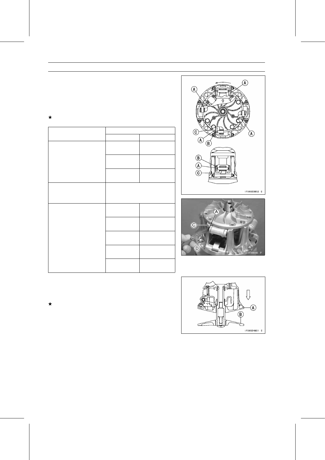
Turn the spider counterclockwise.

•

Measure the resulting clearance [A] between the shoe [B]
and the post [C] on the movable sheave at four posts,
using a thickness gauge [D].

Shoe Side Clearance

Standard: 0.05

∼ 0.20 mm (0.0020 ∼ 0.0079 in.)

If the clearance is not within the specified range, adjust it
according to following chart.

Present Shoes

Clearance Measurement

Part Number

Thickness

7.2 mm

49048-1087

(0.283 in.)

7.3 mm

49048-1088

(0.287 in.)

7.4 mm

up to 0.05 mm (0.0020 in.)

49048-1089

(0.291 in.)

over 0.05 to 0.20 mm

no change

(over 0.0020 to 0.0079 in.)

(49048-1090)

(7.5 mm)

(standard clearance)

(0.295 in.)

7.6 mm

49048-1091

(0.299 in.)

7.7 mm

49048-1092

(0.303 in.)

7.8 mm

49048-1093

(0.307 in.)

7.9 mm

49048-1094

(0.311 in.)

8.0 mm

over 0.20 mm (0.0079 in.)

49048-1095

(0.315 in.)

•

Check that the movable sheave [A] moves smoothly, after
the shoe side clearance adjustment.

○

The movable sheave must move freely towards the fixed
sheave [B].
If the movable sheave does not move smoothly, readjust
the shoe side clearance.

CONVERTER SYSTEM 6-21

Drive Pulley

Drive Pulley Assembly

•

Replace the ramp weight nuts [B] with new ones.

•

Install the ramp weight [A] as shown in the figure.

•

Tighten:

Torque - Ramp Weight Nuts: 6.9 N·m (0.70 kgf·m, 61 in·lb)

•

Check that the ramp weights swing smoothly.

•

Hold the fixed sheave [A] with the drive pulley holders [B]
in a vise.

Special Tools - Drive & Driven Pulley Holder: 57001-1412

Drive & Driven Pulley Holder: 57001-1473

•

Clean the threads of the fixed sheave and spider.

•

Install:

Movable Sheave
Spider [A] and Shoes [B]

○

Align the arrow [C] on the spider with the arrow [D] on the
movable sheave.

○

Insert the shoes so that the rubber side faces inward.

•

Put the drive pulley wrench [A] on the spider [B] and
tighten the bolt [C].

Special Tool - Drive Pulley Wrench: 57001-1549

•

Turn the wrench for tightening.

Torque - Spider: 275 N·m (28.0 kgf·m, 203 ft·lb)

•

Put the spring [A] in the groove of the spider.

•

Align the arrows [B] on the drive pulley cover and spider.

•

Install:

Dowel Pins [C]
Drive Pulley Cover [D]

•

Tighten:

Torque - Drive Pulley Cover Bolts: 13 N·m (1.3 kgf·m, 115

in·lb)

•

Clean the surface of the sheaves with an oil-less cleaning
fluid.

6-22 CONVERTER SYSTEM

Drive Pulley

Bushing Installation

•

Press the cover bushing [A] into the cover [B] using the
special tool so that the end of bushing is flush with the
shoulder [C] in the hole.

Special Tool - Bearing Driver Set: 57001-1129

•

Press the sheave bushing [A] into the movable sheave [B]
using the special tool so that the end of bushing is flush
with the shoulder [C] in the hole.

Special Tool - Bearing Driver Set: 57001-1129

Drive Pulley Installation

•

Clean the following portions with an oil-less cleaning fluid
such as trichloroethylene or acetone, and wipe off any oil
with a clean cloth from the tapers.

Fixed Sheave Tapered Portion [A]
Crankshaft Tapered Portion [B]

WARNING

These cleaning fluids are usually highly flammable
and harmful if breathed for prolonged periods. Be
sure to heed the fluid manufacturer’s warnings.

•

Install the drive pulley, and screw in the drive pulley bolt
with the stepped collar [A] and washers [B] as shown in
the figure.

Bolt Head [C]

•

Hold the drive pulley with the drive pulley holder [A].

Special Tool - Drive Pulley Holder: 57001-1548

•

Tighten:

Torque - Drive Pulley Bolt [B]: 93 N·m (9.5 kgf·m, 69 ft·lb)

CONVERTER SYSTEM 6-23

Drive Pulley

•

Press the ramp weight bushing [B] from the arrow side [A]
into the ramp weight [C] using the special tool so that the
end of bushing is flush with the shoulder [D] in the hole.

Special Tool - Bearing Driver Set: 57001-1129

•

Install the fan cover.

Torque - Fan Cover Bolts: 8.8 N·m (0.90 kgf·m, 78 in·lb)

•

Install the torque converter outer cover (see Torque Con-
verter Outer Cover Installation).


Content   ..  40  41  42  43   ..