Kawasaki Diesel MULE 4010 TRANS 4x4 (KAF950G9). Manual - part 34
 

  Index      Engines     Kawasaki Diesel MULE 4010 TRANS 4x4 (KAF950G9) - service manual


Search            


Content   ..  32  33  34  35   ..


Kawasaki Diesel MULE 4010 TRANS 4x4 (KAF950G9). Manual - part 34


5-12 ENGINE TOP END

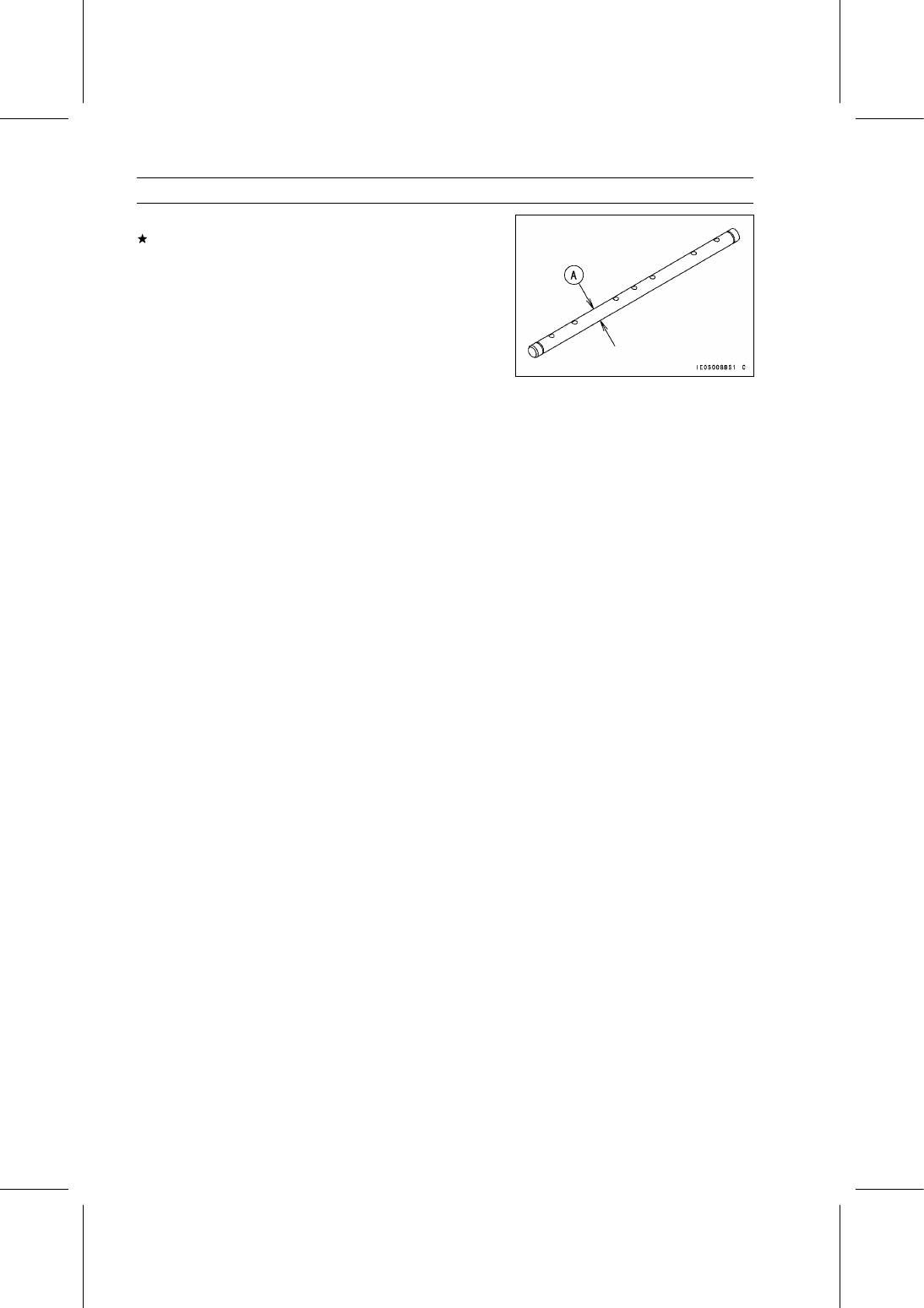
Rocker Shaft and Rocker Arm

•

Measure the diameter [A] of the rocker shaft.
If the shaft has worn past the service limit, replace the
rocker shaft.

Rocker Shaft Diameter

Standard:

9.97

∼ 9.99 mm (0.3925 ∼ 0.3933 in.)

Service Limit:

9.957 mm (0.3920 in.)

ENGINE TOP END 5-13

Valve Lifters

Valve Lifter Removal

•

Remove:

Cylinder Head (see Cylinder Head Removal)
Valve Lifters [A]

○

Mark and record the valve lifter locations so that they can
be installed in their original positions.

Valve Lifter Installation

•

Apply engine oil and install the valve lifters (original posi-
tions).

Valve Lifter Inspection

•

Measure the outside diameter of the valve lifters [A].
If the valve lifter has worn past the service limit, replace
the lifter.

Valve Lifter Outside Diameter

Standard:

17.98 mm (0.7079 in.)

Service Limit:

17.91 mm (0.7051 in.)

5-14 ENGINE TOP END

Valves

Valve Clearance Inspection

•

Refer to the Valve Clearance Inspection in the Periodic
Maintenance chapter.

Valve Clearance Adjustment

•

Refer to the Valve Clearance Adjustment in the Periodic
Maintenance chapter.

Valve Removal

•

Remove:

Cylinder Head (see Cylinder Head Removal)
Valve Stem Cap

○

Mark and record the valve stem cap locations so they can
be installed in their original positions.

•

Using the valve spring compressor [A] remove the split
keepers.

Special Tool - Valve Spring Compressor: 57001-1433

•

Remove:

Retainer [A]
Valve Spring [B]

•

Remove:

Valve [A]
Spring Seat [B]
Oil Seal [C]

Valve Installation

•

Replace the oil seal [A] with a new one.

•

Apply engine oil to the new oil seal.

•

Apply a thin coat of molybdenum disulfide grease to the
valve stem before valve installation.

•

Install:

Oil Seal
Valve [B]
Spring Seat [C]
Valve Spring [D]
Retainer [E]
Split Keepers [F]

ENGINE TOP END 5-15

Valves

Valve Guide Removal

•

Remove:

Valve (see Valve Removal)
Spring Seat
Oil Seal

•

Hammer lightly on the valve guide arbor [A] to remove the
guide from the top of the head.

Special Tool - Valve Guide Arbor, 5.5: 57001-1021

Valve Guide Installation

•

Apply engine oil to the valve guide outer surface before
installation.

•

Press the valve guide [A] in from the top of the head us-
ing the valve guide driver [B] until the driver bottoms on
cylinder head.

Special Tool - Valve Guide Driver: 57001-1432

Valve Seat Inspection

•

Remove the valve (see Valve Removal).

•

Coat the valve seat with machinist’s dye.

•

Push the valve into the guide.

•

Rotate the valve against the seat with a lapping tool.

•

Pull the valve out, and check the seating pattern on the
valve head. It must be the correct width [A] and even all
the way around.

NOTE

○

The valve stem and guide must be in good condition, or
this check will not be valid.

If the valve seating pattern is not correct, repair the seat.

•

Measure the outside diameter [B] of the seating pattern
on the valve seat.
If the outside diameter of the valve seating pattern is too
large or too small, repair the seat.

Valve Seating Surface [C]

Too Wide [G]

Valve [D]

Too Narrow [H]

Valve Seat [E]

Uneven [I]

Good [F]

Valve Seating Surface Width

Standard:

0.8

∼ 1.2 mm (0.0315 ∼ 0.0472 in.)

Valve Seating Surface Outside Diameter

Inlet:

28 mm (1.1024 in.)

Exhaust:

24.5 mm (0.9646 in.)


Content   ..  32  33  34  35   ..