Kawasaki Diesel MULE 4010 TRANS 4x4 (KAF950G9). Manual - part 22
 

  Index      Engines     Kawasaki Diesel MULE 4010 TRANS 4x4 (KAF950G9) - service manual


Search            


Content   ..  20  21  22  23   ..


Kawasaki Diesel MULE 4010 TRANS 4x4 (KAF950G9). Manual - part 22


3-18 FUEL SYSTEM

Fuel Injection Pump

•

Install:

Fuel Injection Pump Drive Gear, Timing Gear Case
Cover and Crankshaft Pulley (see Timing Gear Case
Installation in the Crankshaft/Crankcase chapter)

•

Adjust the fuel injection pump timing (see Fuel Injection
Pump Timing Inspection).

•

Tighten:

Torque - Fuel Injection Pipe Mounting Nuts: 25 N·m (2.5

kgf·m, 18 ft·lb)

Fuel Injection Pipe Clamp Bolts: 7.4 N·m (0.75

kgf·m, 65 in·lb)

•

Adjust:

Maximum Engine Speed (New Injection Pump) (see
Maximum Engine Speed Adjustment)
Idle Speed (see Idle Speed Adjustment in the Periodic
Maintenance chapter)

Fuel Injection Pump Timing Inspection

•

Remove:

Fan Belt Cover (see Cooling Fan Belt Inspection in the
Periodic Maintenance chapter)
Fuel Injection Pipes (see Fuel Injection Pipe Removal)
Cylinder Head Cover (see Rocker Arm Components Re-
moval in the Engine Top End chapter)
Oil Level Gauge Pipe (see End Plate Removal in the
Crankshaft/Crankcase chapter)
Torque Converter Case (see Torque Converter Case Re-
moval in the Converter System chapter)

•

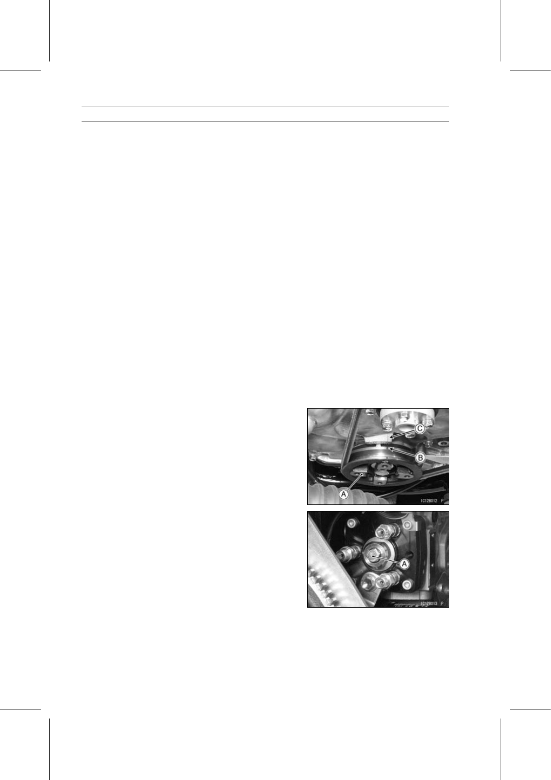
Turn the crankshaft pulley [A] clockwise, and position the
crankshaft at #1 piston TDC on the compression stroke.

○

Align the timing mark [B] on the crankshaft pulley and
reference point [C] on the timing case cover.

○

If the inlet and exhaust valves for #1 cylinder have no
clearance, turn the crankshaft pulley one revolution.

•

Remove the distributor bolt [A].

FUEL SYSTEM 3-19

Fuel Injection Pump

•

Install the dial gauge adapter [A] and dial gauge [B].

Special Tool - Dial Gauge Adapter: 57001-1430

•

Slowly turn the crankshaft pulley counterclockwise about
30° until the dial gauge needle stops. Pump plunger lift is
zero at this point.

•

Set the dial gauge to the “0” position.

•

Slowly turn the crankshaft pulley clockwise, stopping at
#1 piston TDC on the compression stroke.

NOTE

○

Do not turn the crankshaft pulley past TDC. If the crank-
shaft pulley is turned past TDC, turn the crankshaft back
to “0” on the dial gauge and repeat the procedure.

•

Note dial gauge reading.

Injection Timing (Plunger Stroke)

Marking of Injection Nozzle:

Red or Green:

0.81 ±0.03 mm (0.0319 ±0.0012 in.)

None:

0.81 ±0.02 mm (0.0319 ±0.0008 in.)

If the gauge reading is within the specification, the injec-
tion pump is properly timed.
If the gauge reading is not within the specification, adjust
the injection pump timing (see Fuel Injection Pump Timing
Adjustment).

Fuel Injection Pump Timing Adjustment

•

Inspect the fuel injection pump timing.

NOTE

○

Do not turn the crankshaft pulley past TDC. If the crank-
shaft pulley is turned past TDC, turn the crankshaft back
to “0” and repeat the procedure.

3-20 FUEL SYSTEM

Fuel Injection Pump

•

Loosen the fuel injection pump mounting nuts [A].

•

Loosen the fuel injection pump bracket bolt [A].

•

While observing the dial gauge, slowly rotate the fuel in-
jection pump away from the cylinder head until gauge
reads 0.81 ±0.03 mm (0.0319 ±0.0012 in.).

•

Hold the fuel injection pump in this position and tighten
the fuel injection pump mounting nuts.

NOTE

○

Do not rotate the pump past the specification. If the
pump is rotated past the specification, rotate the pump
back toward the cylinder head and repeat the proce-
dure.

•

Tighten:

Torque - Fuel Injection Pump Mounting Nuts: 20 N·m (2.0

kgf·m, 15 ft·lb)

Fuel Injection Pump Bracket Bolts: 20 N·m (2.0

kgf·m, 15 ft·lb)

•

To verify that the timing is correct, turn the crankshaft pul-
ley counterclockwise until the dial indicator reads “0”.

•

Then turn the crankshaft pulley clockwise until the timing
mark on the crankshaft pulley aligns with reference point
on the timing case cover.

•

The indicator should be within the specification.

Injection Timing (Plunger Stroke)

Marking of Injection Nozzle:

Red or Green:

0.81 ±0.03 mm (0.0319 ±0.0012 in.)

None:

0.81 ±0.02 mm (0.0319 ±0.0008 in.)

If the indicator reading is not within the specification, re-
peat the procedure.

•

Remove the dial gauge adapter and dial gauge.

•

Install the distributor head bolt and washer.

•

Tighten:

Torque - Distributor Head Bolt: 17 N·m (1.7 kgf·m, 13 ft·lb)

FUEL SYSTEM 3-21

Fuel Injection Pump

Fuel Injection Pump Inspection and Repair

NOTE

○

Do not disassemble the fuel injection pump and injec-
tion nozzles. The pump and nozzles are produced in
highly automated modern production facilities. They
cannot be assembled by hand in the field.

•

Refer to the troubleshooting section to check of the pump.
If the pump and nozzle are malfunction, replace them, or
consult a reliable repair shop (ex. Denso Service Station).


Content   ..  20  21  22  23   ..