Kawasaki Diesel MULE 4010 TRANS 4x4 (KAF950G9). Manual - part 11
 

  Index      Engines     Kawasaki Diesel MULE 4010 TRANS 4x4 (KAF950G9) - service manual


Search            


Content   ..  9  10  11  12   ..


Kawasaki Diesel MULE 4010 TRANS 4x4 (KAF950G9). Manual - part 11


2-22 PERIODIC MAINTENANCE

Periodic Maintenance Procedures

•

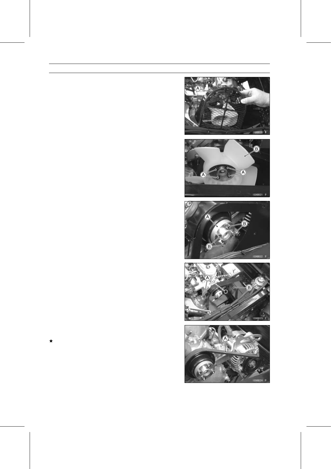
Remove the fan cover [A] as shown in the figure.

•

Remove:

Fan Mounting Bolts [A]
Cooling Fan [B]
Spacer

•

Reinstall the spacer [A] and tighten the fan mounting bolts
[B] temporary.

Torque - Fan Mounting Bolts: 8.8 N·m (0.90 kgf·m, 78 in·lb)

•

Remove:

Bolts [A]
Fan Belt Cover [B]

•

Check the cooling fan belt [A] for excessive wear crack or
broken.
If necessary, replace the belt with a new one.

PERIODIC MAINTENANCE 2-23

Periodic Maintenance Procedures

•

Check the fan belt deflection.

○

Use a ruler [A], push the belt with 98 N (10 kgf, 22 lb)
force.

Push Gauge [B]

Fan Belt Deflection

Standard: 9.5

∼ 11.5 mm (0.37 ∼ 0.45 in.)

If the deflection is incorrect, adjust it.

•

Loosen the alternator adjusting bracket bolt [A] and alter-
nator mounting bolt [B].

Alternator [C]

•

Adjust the fan belt deflection.

○

Use a ruler, push the belt with 98 N (10 kgf, 22 lb) force.

•

Tighten the bolts.

Torque - Alternator Adjusting Bracket Bolts: 20 N·m (2.0

kgf·m, 15 ft·lb)

Alternator Mounting Bolt: 39 N·m (4.0 kgf·m, 29

ft·lb)

•

When installing the water pipe and water hose, note the
following.

○

Check that the damper [A] is in place on the water pipe
[B].

Air Bleed Bolt [C]
5

∼ 10 mm (0.20 ∼ 0.40 in.) [D]

If the damper is damaged or deteriorated, replace it.

○

Insert the water pipe [A] up to the end of the bending
radius of the water hose [B] as shown in the figure.

Air Bleed Bolt [C]

○

Make sure that there is clearance between the water pipe
and the fan cover.

Engine Top End

Valve Clearance Inspection

NOTE

○

Valve clearance must be checked when the engine is
cold (at room temperature).

•

Remove:

Fan Belt Cover (see Cooling Fan Belt Inspection)
Cylinder Head Cover (see Rocker Arm Components Re-
moval in the Engine Top End chapter)

2-24 PERIODIC MAINTENANCE

Periodic Maintenance Procedures

•

Turn the crankshaft pulley [A] clockwise so that the timing
mark [B] on the pulley aligns with the reference point [C]
on the timing gear case cover.

○

Check that the rocker arms at #1 cylinder are free.
If not, turn the pulley one more turn to free the rocker
arms.

•

Using a thickness gauge [A], measure the valve clearance
between the rocker arm [B] and the valve stem cap [C].
If the valve clearance is incorrect, adjust it.

Valve Clearance

Standard: 0.20 mm (0.0079 in.)

○

When positioning #1 piston TDC at the compression
stroke:

Inlet valve clearance of #1 and #3 cylinders
Exhaust valve clearance of #1 and #2 cylinders
Front [A]
Measuring Valve [B]

○

Turn the crankshaft pulley 360° clockwise.

Inlet valve clearance of #2 cylinder
Exhaust valve clearance of #3 cylinder
Front [A]
Measuring Valve [B]

Valve Clearance Adjustment

•

Loosen the valve adjusting screw locknut [A].

•

Turn the valve adjusting screw [B] until the correct clear-
ance is obtained.

•

Holding the adjusting screw, tighten the locknut.

Torque - Valve Adjusting Screw Locknuts: 11 N·m (1.1

kgf·m, 97 in·lb)

PERIODIC MAINTENANCE 2-25

Periodic Maintenance Procedures

Spark Arrester Cleaning

WARNING

The muffler can become extremely hot during nor-
mal operation and cause severe burns. Since the
engine must be running during this procedure, wear
heat-resistant gloves while cleaning the spark ar-
rester.

•

Remove the drain plug [A] from the muffler [B].

•

Apply the parking brake.

•

In an open area away from combustible materials, start
the engine with the gear shift lever in the N (neutral) po-
sition.

•

Raise and lower engine speed while tapping on the muf-
fler with a rubber mallet until the carbon particles are
purged from the muffler.

DANGER

Exhaust gas contains carbon monoxide, a color-
less, odorless poisonous gas.

Inhaling carbon

monoxide can cause serious brain injury or death.
DO NOT run the engine in enclosed areas. Operate
only in a well-ventilated area.

•

Stop the engine.

•

Install the drain plug.

Converter System

Drive Belt Inspection

•

Remove the drive belt (see Drive Belt Removal in the
Converter System chapter).

•

Measure the width [A] of the belt.
If any measurements exceed the service limit, replace the
belt.

Belt Width

Standard:

34.1 mm (1.34 in.)

Service Limit: 32.6 mm (1.28 in.)

•

Check the belt for wear, cracks, breaks or peeling.
If necessary, replace the belt with a new one.

Belt [A]
Crack [B]
Broken [C]

NOTE

○

Whenever the belt is replaced, inspect the drive and the
driven pulleys.


Content   ..  9  10  11  12   ..