Technology of watch production - part 53
 

  Index      Books     Technology of watch production (Tarasov) 1964 year


Search            


Content   ..  51  52  53  54   ..


Technology of watch production - part 53


The  plate  deforms  (buckles )  as  a  result of the  considerable local  remo val 

of metal  and it  accordingly undergoes  a  stress  relief operation after which 

the  dial  side  of the plate  is  either turned or shaped.  Plates  and  cocks 

(bridges )  are  s tress  relieved in  the  PN- 3 1 6  electric pit furnace  at  2 3 0 -

2 5 0°C  for  2  hours . 

Piercing 

Center punching 

• 

FIGURE  5.  Pin holes in the plate 

a-preliminary drilling;  b-punch-piercing of holes with simultaneous center punching of a group of other holes; 
c-machining the center-punched holes. 

Finish milling of the recesses  for the train,  escapement and balance,  and 

the boring  of  the  s tepped barrel recess follow.  These operations  bring the 

plate to  the  shape  shown in Figure  6 .  

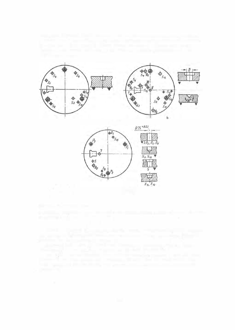
Next,  1 4  holes  are  rough- s haved  leaving  a n  allowance  for the  finish 

shaving and  the  remaining  1 5  holes  are pierced  (Figure 

7 ). 

The  holes  for  the  winding s tem  and  the  fas tening  screws  of the  dial  feet 

(Figure  8)  are then machined.  Finally,  24 holes  for the cock and bridge 

fitting pins  and  for the train,  escapement  and  balance arbors  are  s haved 

(Figure  9 ). 

2 0 9  

The  machining  of  the  recess es  and  projections  on  the  dial  side  of  the plate 

for the  winding  gear and  the  motion  work is  now performed  (Figure  1 0  

)

.  The 

windows  for the  winding pinion and  the  claw clutch are  shave d .  

Section AA 

FIGURE 6.  View of the " Pobeda" 

brand watch plate after  machining 

the recesses from the cock side 

Section BB 

FIGURE  7 .   Disposition of the holes 
in the plate ( view from the cock side) 

FIGURE  8.  Lateral holes in the plate 

The  holes  are  c ountersunk from  the  dial  and  cock side s ,   and  threads 

are  tapped in  holes  from  both sides .  A  s houlder is  turned for  m ounting the 

case  (Figure  1 1  

); 

and finally,  the  cleaning operations  are performed. 

2 1 0 

t. s,-s�: 

FIGURE  9.  Plate  holes after shaving.  The hole diameters are : 

1 - o.o56+ 0·012;  S1- s6-1 .282+ 0·005;  S7- S8- o.505+ 0·005 ;  S9- S10-o.95 + 0"02; 
S 15 -0.49+ 0.005 ;  I -1. 01+ 0.005;  II - 0.655+ 0.005;  Ill,  IV,  V ,  VI -0. 982+ 0.005; 

+ 0.005 

5-0.54 

0.005 

· 

n-S14 -0.535 

VII-1 .182 

+ 0"005; 

FIGURE  10.  Plate  recesses (view from 
the dial side) 

FIGURE  11.  View  of the plate from 
the  cock  side  after the completion of 

all machining operations 

TURNING  AND  SHAPING  OF  FACE  PLANES  AND  BORING  OF  RECESSES 

The face planes of plates ,   cocks  and  bridges  are faced in  order to  provide 

a  more  accurate  m ounting and positioning  base  for  the subsequent m echan­
ical  operations .  The  surfaces  are faced  either by turning  on  the  S - 8 1A 

s emiautomatic lathe,  or  by shaping  on  the  S - 1 8 8  rotary shaping machine . 

The  S- 8 1A  two- spindle  s emiautomatic lathe  (Figure  1 2 )  consists  of  the 

bas e  ( 1 ),  housing the  drive,  the  camshaft housings  (2 ),  the  headstocks  ( 3 )  
and  the  slides  ( 4 )

T h e   b a s e  

1  )  of  the  machine  is  a  light  cast- iron block  of  rectangular 

form .  The  electric  motor is  m ounted  on a  plate  inside  the  bas e  (at its  cen­

ter).  A  flange  mounting the cam shaft  drive  is m ounted  on the back wall  in 

the  lower part  of the bas e .  

T h e   c a m  s h a f t   h o u s i n g  (2 )  i s  a complex  iron casting,  inside  which 

are  mounted  the  countershaft,  the  transmission  shaft,  and  the  shaft  for  the 

2 1 1  

right- hand  and  left- hand  slides .  The  housing is  fastened to  the  base  by 

means of screws and serves as base for the two headstocks and the two  slides . 

T h e   h e a d s t o c k   ( 3 )  is  the  main assembly of  the  machine  and  is housed 

in a  cast-iron body ( 1 )  (Figure  13 ).  The  hollow spindle  (2 )  is  mounted in 

two  bronze  bearings .  The spindle  pulley revolves  freely on ball  bearings 
and powers  the  spindle through the  cone  of the  friction clutch  (4 ) which is 

p ressed against  the pulley cone by four  sp rings  ( 5 )  and  connected with the 

spindle  through  the  keyed  sleeve  ( 6  ). 

When  the  machining cycle is  ended,  the frictional  clutch is  dis engaged 

by the  cone  being  moved  to  the  right,  along the  key,  by  the  lever  ( 7 ) which 

is  controlled by  cam  ( 1 9 )  on the  camshaft  (see Figure  1 5 ).  When  the  ma­

chining cycle begins again,  the friction clutch is freed and engages  the pulley 
again,  under the  action  of springs  (5 ),  thus  s tarting the  spindl e .  

FIGURE  12 .  General view  of the S-81A two-spindle semiautomatic lathe : 

1-base;  2-camshaft housing;  3-headstock ;  4-slides. 

The  plate  is  gripped  in the collet chuck  (8 ).  C ontour plates  ( 1 0 )  are 

fastened to the collet face  ( 9 )  in o rder to hold the shaped  parts on their con­

tour.  When the foot p edal  is  pressed,  the sleeve  ( 1 1 )  is  moved to the right 

by a  fork.  The  s top  levers  ( 1 2 )  are  thereby freed to  open  under the  action 

of the bar spring  ( 1 3 ) .   The bar  ( 1 4 )  advances  to  the  right  together  with the 

collet  ( 9 ),  thus  opening the  collet and freeing the part.  A fter the  machined 

part has  been  unloaded and  the  next  part  to be  machined has  been positioned, 

the  foot pedal  is  released,  the  sleeve  is  returned to  the l eft by the  springs 

( 1 5 )  and presses  on the  right-hand  ends  of  the  s top levers .  The  s top  l evers 

forc e  the bar back (by pressing on its  shoulder) and the  collet  grips  the part. 

The collet is  threaded to the bar and is  positioned in the chuck by means 

of the pin  ( 1 6  ) .  

2 1 2 


Content   ..  51  52  53  54   ..