Cessna 162 Skycatcher Aircraft Pilot. Operating Handbook (2009) - page 2
CESSNA
SECTION 4
MODEL 162
WEIGHT AND BALANCE/
GARMIN G300
EQUIPMENT LIST
WEIGHT AND BALANCE/
EQUIPMENT LIST
TABLE OF CONTENTS
Page
Introduction
4-3
Comprehensive Equipment List
4-4
Airplane Weighing Procedures
4-8
Airplane Weighing Form
4-9
Sample Weight and Balance Record
4-13
Weight And Balance
4-15
Baggage Tiedown
4-16
Sample Loading Problem
4-17
Loading Graph
4-21
Loading Arrangements
4-23
Internal Cabin Dimensions
4-25
Center Of Gravity Moment Envelope
4-27
Center of Gravity Limits
4-29
162PHUS-00
U.S.
4-1/4-2
CESSNA
SECTION 4
MODEL 162
WEIGHT AND BALANCE/
GARMIN G300
EQUIPMENT LIST
INTRODUCTION
This section describes the procedure for establishing the basic empty
weight and moment of the airplane. Sample forms are provided for
reference. Procedures for calculating the weight and moment for
various operations are also provided. For additional information
regarding Weight and Balance procedures, refer to the Aircraft Weight
and Balance Handbook (FAA-H-8083-1). A comprehensive list of
Cessna equipment available for this airplane is included in this section.
Specific information regarding the weight, arm, moment and installed
equipment for this airplane as delivered from the factory can be found
in the plastic envelope in the back of this POH.
WARNING
IT IS THE RESPONSIBILITY OF THE PILOT TO MAKE
SURE THE AIRPLANE IS LOADED PROPERLY.
OPERATION OUTSIDE OF PRESCRIBED WEIGHT AND
BALANCE LIMITATIONS COULD RESULT IN AN
ACCIDENT AND SERIOUS OR FATAL INJURY.
162PHUS-00
U.S.
4-3
SECTION 4
CESSNA
WEIGHT AND BALANCE/
MODEL 162
EQUIPMENT LIST
GARMIN G300
COMPREHENSIVE EQUIPMENT LIST
Figure 4-1 is a comprehensive list of all Cessna equipment which is available for
the Model 162 airplane equipped with Garmin G300 Integrated Cockpit System
(Serials 16200001 and On). This comprehensive equipment list provides the
following information in column form:
In the ITEM NO column, each item is assigned a coded number. The first two
digits of the code represent the identification of the item within Air Transport
Association Specification 100 (11 for Paint and Placards; 24 for Electrical
Power; 77 for Engine Indicating, etc.). These assignments also correspond to
the Maintenance Manual chapter for the airplane. After the first two digits, items
receive a unique sequence number (01, 02, 03, etc.). After the sequence
number, a suffix letter is assigned to identify equipment as a required item, a
standard item or an optional item.
Suffix letters are as follows:
R = Required items or equipment for ASTM certification.
S =
Standard equipment items.
O = Optional equipment items replacing required or standard items.
A =
Optional equipment items which are in addition to required or
standard items.
In the EQUIPMENT LIST DESCRIPTION column, each item is assigned a
descriptive name to help identify its function.
In the REF DRAWING column, a Cessna drawing number is provided which
corresponds to the item.
NOTE
If additional equipment is to be installed, it must be done in
accordance with the reference drawing, service bulletin or a separate
ASTM approval.
In the WT LBS and ARM INS columns, information is provided on the weight (in
pounds) and arm (in inches) of the equipment item.
NOTE
• Unless otherwise indicated, true values (not net change values)
for the weight and arm are shown. Positive arms are distances aft
of the airplane datum; negative arms are distances forward of the
datum.
• Asterisks (*) in the weight and arm column indicate complete
assembly installations. Some major components of the assembly
are listed on the lines immediately following. The sum of these
major components does not necessarily equal the complete
assembly installation.
4-4
U.S.
162PHUS-00
CESSNA
SECTION 4
MODEL 162
WEIGHT AND BALANCE/
GARMIN G300
EQUIPMENT LIST
REF
WT
ARM
ITEM NO
EQUIPMENT LIST DESCRIPTION
DRAWING
LBS
INS.
11 - PAINT AND PLACARDS
11-01-S
PAINT, OVERALL WHITE WITH COLOR STRIPE
0900001
16.83*
174.29
- OVERALL WHITE COLOR
0900001
16.58
174.38
- COLOR STRIPING
0919002
0.25
168.35
21 - AIR CONDITIONING
21-01-S
VENTILATORS, ADJUSTABLE, CABIN AIR
0914100
0.86
122.88
21-02-S
CABIN HEATER SYSTEM, SHROUDED MUFFLER
0914100
1.01
99.15
TYPE
21-03-R
AVIONICS COOLING FAN - S4000-4
0918101
0.30
116.06
22 - AUTO FLIGHT
22-01-O
AUTOPILOT INSTALLATION
0901120
7.17
111.43
23 - COMMUNICATIONS
23-01-R
NAV/COM/GPS #1 COMPUTER
- SL40 INTEGRATED AVIONICS UNIT
0918101
2.10
117.22
- CI2480-201 VHF COMM/GPS ANTENNA
0918123
0.56
164.78
- CI420-10 XM ANTENNA AND CABLE ASSY
0918503
1.02
147.49
23-02-O
AUDIO INTERCOM
- PM3000 AUDIO PANEL
0918504
1.04
118.31
24 - ELECTRICAL POWER
24-01-R
ALTERNATOR, 12 VOLT, 60 AMP
0950000
6.80
83.36
24-02-R
BATTERY, 12 VOLT, 14.0 AMP HOUR - PC545
0918130
11.40
98.35
24-03-S
BATTERY, STANDBY 12 VOLT - PS-1208
0918104
0.8
109.44
24-04-O
GROUND SERVICE POWER RECEPTACLE
0918505
3.33
97.62
25 - EQUIPMENT/FURNISHINGS
25-01-R
SEAT, PILOT
0919021
7.79
146.23
25-02-S
SEAT, FRONT PASSENGER
0919021
7.79
146.23
25-03-R
SEAT BELT AND SHOULDER HARNESS,
0919022
1.47
161.57
MANUAL ADJUST, PILOT
25-04-S
SEAT BELT AND SHOULDER HARNESS,
0919022
1.47
161.57
MANUAL ADJUST, FRONT PASSENGER
25-05-S
BAGGAGE RESTRAINT NET
0919030
0.10
176.21
25-06-S
PILOT'S OPERATING HANDBOOK
2.00
160.59
25-07-R
PILOT’S CHECKLIST
1.00
160.59
25-08-S
GARMIN G300 PILOT’S GUIDE
1.00
160.59
25-09-S
FUEL SAMPLING CUP
1.00
160.59
25-10-S
AK-450-C - 2 FREQUENCY ELT
0918114
2.50
201.79
- ANTENNA AND CABLE - 450017-C
0.16
198.34
25-11-O
AK-451-C - 3 FREQUENCY ELT
0918508
2.20
201.79
- ANTENNA AND CABLE - 450017-1B-C
0.18
198.34
25-12-O
SUN VISORS (SET OF TWO)
0911010
1.65
126.44
25-13-O
BALLISTIC RECOVERY SYSTEM
0901105
34.86
168.50
Figure 4-1 (Sheet 1 of 3)
162PHUS-03
U.S.
4-5
SECTION 4
CESSNA
WEIGHT AND BALANCE/
MODEL 162
EQUIPMENT LIST
GARMIN G300
REF
WT
ARM
ITEM NO
EQUIPMENT LIST DESCRIPTION
DRAWING
LBS
INS.
25 - EQUIPMENT/FURNISHINGS (Continued)
25-14-O
TAIL TIEDOWN GUARD
0901130
0.14
286.38
25-15-R
AFT BULKHEAD CLOSEOUT NET
0919017
1.13
191.32
26 - FIRE PROTECTION
26-01-O
FIRE EXTINGUISHER
0901600-1
2.77*
160.59*
- FIRE EXTINGUISHER, HAND TYPE
A344T
2.53
160.59
- MOUNTING CLAMP AND HARDWARE
0.24
160.59
27 - FLIGHT CONTROLS
27-01-R
DUAL CONTROLS
- CONTROL STICK ASSEMBLY
0961510
0.85
122.98
- RUDDER AND BRAKE PEDALS
0961331
0.46
108.02
28 - FUEL
28-01-R
FUEL INDICATOR (EACH)
0916101
0.08
136.02
28-02-O
FUEL PRIMER ASSEMBLY
0901200
0.63
106.60
31 - INDICATING/RECORDING SYSTEM
31-01-R
PNEUMATIC STALL WARNING SYSTEM
0914300
0.55
127.11
31-02-R
OUTSIDE AIR TEMPERATURE (OAT) PROBE
0918121
0.30
166.03
32 - LANDING GEAR
32-01-R
WHEEL BRAKE AND TIRE, 5.00 X 5 MAIN (2)
0941000
- WHEEL ASSY (EACH)
4.16
149.52
- BRAKE ASSY (EACH)
1.46
151.73
- TIRE AND TUBE, 4-PLY, 5.00 X 5, BLACKWALL
5.62
149.52
(EACH)
32-02-R
WHEEL AND TIRE ASSY, 4.00 X 5 NOSE
0942000
- WHEEL ASSY
3.50
86.92
- TIRE AND TUBE, 8-PLY, 4.00 X 5, BLACKWALL
2.38
86.92
32-03-O
WHEEL FAIRING AND INSTALLATION
- WHEEL FAIRING, NOSE
0942200
2.57
87.55
- WHEEL FAIRINGS, MAIN (EACH)
0941200
3.77
151.52
33 - LIGHTS
33-01-S
COCKPIT LIGHT (LED) - CL5190
0918103
0.12
146.00
33-02-R
NAV/STROBE LIGHT (EACH)
0928007
0.97
142.74
33-03-S
LANDING/TAXI LIGHT
0928007
1.36
129.28
34 - NAVIGATION
34-01-R
PFD DISPLAY
- GDU 370 DISPLAY
0918101
1.56
121.56
34-02-O
MFD DISPLAY
- GDU 375 DISPLAY
0918502
2.40
121.56
34-03-R
ATTITUDE HEADING REFERENCE SENSOR
(ADAHRS)
- GSU 73 ADAHRS
0918109
3.33
104.32
Figure 4-1 (Sheet 2)
4-6
U.S.
162PHUS-03
CESSNA
SECTION 4
MODEL 162
WEIGHT AND BALANCE/
GARMIN G300
EQUIPMENT LIST
REF
WT
ARM
ITEM NO
EQUIPMENT LIST DESCRIPTION
DRAWING
LBS
INS.
34 - NAVIGATION (Continued)
34-04-R
TRANSPONDER
- GTX-327 TRANSPONDER
0918101
2.40
118.76
- TRANSPONDER ANTENNA
0918122
0.06
116.91
34-05-O
COMPASS, MAGNETIC
0918509
1.16
124.47
61 - PROPELLER
61-01-R
FIXED
PITCH
COMPOSITE
PROPELLER
ASSEMBLY
- MCCAULEY 67 INCH COMPOSITE PROPELLER
1L100/LSA6754
9.42
65.03
- MCCAULEY 3.115 INCH PROPELLER SPACER
B-7925
2.02
65.03
61-02-O
FIXED
PITCH
ALUMINUM
PROPELLER
ASSEMBLY
- MCCAULEY 67 INCH ALUMINUM PROPELLER
1A162/TCD6754
22.79
65.03
- MCCAULEY 3.115 INCH PROPELLER SPACER
B-7925
2.02
65.03
61-03-R
SPINNER INSTALLATION, PROPELLER
- SPINNER SHELL
D-7945
0.91
65.03
- SPINNER FRONT SUPPORT ASSEMBLY
C-7961
0.20
65.03
- SPINNER BULKHEAD ASSEMBLY
D-7962
1.06
65.03
- MOUNTING HARDWARE
1.52
65.03
71 - POWERPLANT
71-01-R
FILTER, INDUCTION AIR
0950000
0.50
83.00
71-02-O
WINTERIZATION KIT INSTALLATION
0901260
1.48
72.87
(INSTALLED ARM SHOWN)
- BREATHER TUBE INSULATION
0901250-5, -10
0.58
77.74
- COWL INLET COVERS (INSTALLED)
0901250-1, -2
0.90
69.73
72 - ENGINES
72-01-R
ENGINE, TELEDYNE CONTINENTAL MOTORS
0950000
213.78
83.95
O-200D
77 - ENGINE INDICATING
77-01-R
ENGINE TACHOMETER SENSOR
0950000
0.02
92.29
77-02-O
EXHAUST THERMOCOUPLE
0918506
0.04
78.64
78 - EXHAUST
78-01-R
EXHAUST SYSTEM
9950100
8.00
77.67
79 - OIL
79-01-R
OIL COOLER INSTALLATION
0950000
3.83
83.36
79-02-R
OIL PRESSURE SENSOR - P165-5281
0950000
0.32
80.81
79-03-R
OIL TEMPERATURE SENSOR - S2335-1
0950000
0.15
80.81
79-04-O
OIL QUICK DRAIN INSTALLATION
0901240
0.06
90.08
Figure 4-1 (Sheet 3)
162PHUS-03
U.S.
4-7
SECTION 4
CESSNA
WEIGHT AND BALANCE/
MODEL 162
EQUIPMENT LIST
GARMIN G300
AIRPLANE WEIGHING PROCEDURES
1.
Preparation:
a. Inflate tires to recommended operating pressures.
b. Defuel airplane. Refer to the Maintenance Manual.
c. Service engine oil as required to obtain a normal full
indication (approximately 5 quarts on dipstick).
d. Raise flaps to the fully retracted position.
e. Place all control surfaces in neutral position.
f.
Remove all non-required items from airplane.
2.
Level:
a. Place scales under each wheel (minimum scale capacity,
1000 pounds).
b. Deflate the nose tire to properly center the bubble in the
level (Refer to Figure 4-2).
3.
Weigh:
a. Weigh airplane in a closed hangar to avoid errors caused by
air currents.
b. With the airplane level and brakes released, record the
weight shown on each scale. Deduct the tare, if any, from
each reading.
4.
Measure:
a. Obtain measurement A by measuring horizontally (along the
airplane centerline) from a line stretched between the main
wheel centers to a plumb bob dropped from the firewall.
b. Obtain measurement B by measuring horizontally and
parallel to the airplane centerline, from center of nosewheel
axle, left side, to a plumb bob dropped from the line between
the main wheel centers. Repeat on right side and average
the measurements.
5.
Using weights from step 3 and measurements from step 4, the
Basic Empty Weight and C.G. can be determined by completing
Figure 4-2 (Sheet 3 or Sheet 4).
6.
Changes to the Airplane Weight and Balance due to alteration or
repair must be documented in a permanent record within the
POH similar to that shown in Figure 4-3.
7.
A new Basic Empty Weight and CG Arm based on actual
airplane weight (as weighed) is required after a major repair or
alteration. It is recommended that the airplane be weighed to
verify Basic Empty Weight and CG Arm at intervals not to
exceed 5 years.
4-8
U.S.
162PHUS-00

CESSNA
SECTION 4
MODEL 162
WEIGHT AND BALANCE/
GARMIN G300
EQUIPMENT LIST
AIRPLANE WEIGHING FORM - U.S. UNITS
Figure 4-2* (Sheet 1 of 4)
162PHUS-01
U.S.
4-9

SECTION 4
CESSNA
WEIGHT AND BALANCE/
MODEL 162
EQUIPMENT LIST
GARMIN G300
AIRPLANE WEIGHING FORM - METRIC UNITS
Figure 4-2* (Sheet 2)
4-10
U.S.
162PHUS-01

CESSNA
SECTION 4
MODEL 162
WEIGHT AND BALANCE/
GARMIN G300
EQUIPMENT LIST
AIRPLANE WEIGHING FORM - U.S. UNITS
Figure 4-2 (Sheet 3)
162PHUS-00
U.S.
4-11

SECTION 4
CESSNA
WEIGHT AND BALANCE/
MODEL 162
EQUIPMENT LIST
GARMIN G300
AIRPLANE WEIGHING FORM - METRIC UNITS
Figure 4-2 (Sheet 4)
4-12
U.S.
162PHUS-00
CESSNA
SECTION 4
MODEL 162
WEIGHT AND BALANCE/
GARMIN G300
EQUIPMENT LIST
SAMPLE WEIGHT AND BALANCE RECORD - U.S.
Figure 4-3 (Sheet 1 of 2)
162PHUS-00
U.S.
4-13
SECTION 4
CESSNA
WEIGHT AND BALANCE/
MODEL 162
EQUIPMENT LIST
GARMIN G300
SAMPLE WEIGHT AND BALANCE RECORD - METRIC
Figure 4-3 (Sheet 2)
4-14
U.S.
162PHUS-00
CESSNA
SECTION 4
MODEL 162
WEIGHT AND BALANCE/
GARMIN G300
EQUIPMENT LIST
WEIGHT AND BALANCE
The following information will enable you to operate your Cessna within
the prescribed weight and center of gravity limitations. To determine
weight and balance, use the Sample Loading Problem (Figure 4-4),
Loading Graph (Figure 4-5), and Center of Gravity Moment Envelope
(Figure 4-8) as follows:
Enter the appropriate basic empty weight and moment/1000 from the
weight and balance records for your airplane in the YOUR AIRPLANE
column of the Sample Loading Problem.
NOTE
In addition to the basic empty weight and moment noted on
these records, the C.G. arm (FS) is also shown, but need
not be used on the Sample Loading Problem. The moment
which is shown must be divided by 1000 and this value
used as the moment/1000 on the loading problem.
Use the Loading Graph to determine the moment/1000 for each
additional item to be carried; then list these on the loading problem.
NOTE
Loading Graph information for the pilot, passenger and
baggage is based on baggage loaded in the center of the
baggage areas as shown on the Loading Arrangements
diagram. For loadings which may differ from these, the
Sample Loading Problem lists fuselage stations (FS) for
these items to indicate their forward and aft C.G. range
limitations (baggage area limitation). Refer to Figures 4-6
and
4-7 for additional loading information. Additional
moment calculations, based on the actual weight and C.G.
arm (FS) of the item being loaded, must be made if the
position of the load is different from that shown on the
Loading Graph.
Total the weights and moments/1000 and plot these values on the
Center of Gravity Moment Envelope to determine whether the point
falls within the envelope, and if the loading is acceptable.
(Continued Next Page)
162PHUS-01
U.S.
4-15
SECTION 4
CESSNA
WEIGHT AND BALANCE/
MODEL 162
EQUIPMENT LIST
GARMIN G300
WEIGHT AND BALANCE (Continued)
BAGGAGE TIEDOWN
A nylon baggage net, having four tiedown straps, is provided as
standard equipment to secure baggage on the cabin floor. Six eyebolts
serve as attaching points for the net. A placard located on the right side
of the baggage compartment, below the window, defines the weight
limitations in the baggage areas.
NOTE
Maximum weight in the baggage compartment area is 50
pounds (22.68 kg) with a maximum floor loading of 8
pounds per square foot (39.05 kilograms per square meter).
4-16
U.S.
162PHUS-01

CESSNA
SECTION 4
MODEL 162
WEIGHT AND BALANCE/
GARMIN G300
EQUIPMENT LIST
SAMPLE LOADING PROBLEM - U.S. UNITS
WEIGHT AND MOMENT
TABULATION
SAMPLE
YOUR
ITEM DESCRIPTION
AIRPLANE
AIRPLANE
Weight
Moment
Weight
Moment
(lbs)
(lb-ins/
(lbs)
(lb-ins/
1000)
1000)
1 - Basic Empty Weight
(Use the data pertaining to your airplane
as it is presently equipped. Includes
unusable fuel and full oil)
834
110.1
2 - Usable Fuel (At 6 Lbs./Gal.)
- Standard Fuel - 24 Gallons Maximum
144
20.6
- Reduced Fuel - 12 Gallons
3 - Pilot and Front Passenger (FS 142)
300
42.6
4 - Baggage (FS 155 to 190)
50 Pounds Maximum
46
7.9
5 - RAMP WEIGHT AND MOMENT
1324
181.2
6 - Fuel allowance for engine start, taxi and
runup
-4.0
-0.6
7 - TAKEOFF WEIGHT AND MOMENT
(Subtract Step 8 from Step 7)
1320
180.6
8 - Locate this point (1320 at 180.6) on the Center of Gravity Moment Envelope,
and since this point falls within the envelope, the loading is acceptable.
Figure 4-4 (Sheet 1 of 4)
162PHUS-00
U.S.
4-17

SECTION 4
CESSNA
WEIGHT AND BALANCE/
MODEL 162
EQUIPMENT LIST
GARMIN G300
SAMPLE LOADING PROBLEM - METRIC UNITS
WEIGHT AND MOMENT
TABULATION
SAMPLE
YOUR
ITEM DESCRIPTION
AIRPLANE
AIRPLANE
Weight
Moment
Weight
Moment
(kgs)
(kg-mm/
(kgs)
(kg-mm/
1000)
1000)
1 - Basic Empty Weight
(Use the data pertaining to your airplane
as it is presently equipped. Includes
unusable fuel and full oil)
378.3
1268.4
2 - Usable Fuel (At 0.72 Kg./Liter)
- Standard Fuel - 90.82 Liters Maximum
65.4
244.5
- Reduced Fuel - 45.41 Liters
3 - Pilot and Front Passenger (FS 3607)
136.1
490.9
4 - Baggage (FS 3937 to 4826)
22.6 Kilograms Maximum
19.9
86.9
5 - RAMP WEIGHT AND MOMENT
599.7
2090.7
6 - Fuel allowance for engine start, taxi and
runup
-1.8
-6.6
7 - TAKEOFF WEIGHT AND MOMENT
(Subtract Step 8 from Step 7)
597.9
2084.1
8 - Locate this point (597.9 at 2084.1) on the Center of Gravity Moment Envelope,
and since this point falls within the envelope, the loading is acceptable.
Figure 4-4 (Sheet 2)
4-18
U.S.
162PHUS-00

CESSNA
SECTION 4
MODEL 162
WEIGHT AND BALANCE/
GARMIN G300
EQUIPMENT LIST
SAMPLE LOADING PROBLEM - U.S. UNITS
NOTE
When several loading configurations are representative of
your operations, it may be useful to fill out one or more of
the above columns so specific loadings are available at a
glance.
Figure 4-4 (Sheet 3)
162PHUS-00
U.S.
4-19

SECTION 4
CESSNA
WEIGHT AND BALANCE/
MODEL 162
EQUIPMENT LIST
GARMIN G300
SAMPLE LOADING PROBLEM - METRIC UNITS
YOUR
YOUR
YOUR
AIRPLANE
AIRPLANE
AIRPLANE
Weight
Moment
Weight
Moment
Weight
Moment
(Kgs)
(Kgs-mm/
(Kgs)
(Kgs-mm/
(Kgs)
(Kgs-mm/
1000)
1000)
1000)
NOTE
When several loading configurations are representative of
your operations, it may be useful to fill out one or more of
the above columns so specific loadings are available at a
glance.
Figure 4-4 (Sheet 4)
4-20
U.S.
162PHUS-00

CESSNA
SECTION 4
MODEL 162
WEIGHT AND BALANCE/
GARMIN G300
EQUIPMENT LIST
LOADING GRAPH - U.S. UNITS
Figure 4-5 (Sheet 1 of 2)
162PHUS-00
U.S.
4-21

SECTION 4
CESSNA
WEIGHT AND BALANCE/
MODEL 162
EQUIPMENT LIST
GARMIN G300
LOADING GRAPH - METRIC UNITS
Figure 4-5 (Sheet 2)
4-22
U.S.
162PHUS-00
CESSNA
SECTION 4
MODEL 162
WEIGHT AND BALANCE/
GARMIN G300
EQUIPMENT LIST
LOADING ARRANGEMENTS - U.S. UNITS
*Pilot and front seat passenger center of gravity for average
occupant.
**Arm measured to the center of the areas shown.
NOTE
• All dimensions shown are in inches.
• The usable fuel C.G. arm is located at FS 143.26.
• The aft baggage wall (approximate FS 190.00) can be
used as a convenient interior reference point for
determining the location of baggage area fuselage
stations.
Figure 4-6* (Sheet 1 of 2)
162PHUS-01
U.S.
4-23
SECTION 4
CESSNA
WEIGHT AND BALANCE/
MODEL 162
EQUIPMENT LIST
GARMIN G300
LOADING ARRANGEMENTS - METRIC UNITS
*Pilot and front seat passenger center of gravity for average
occupant.
**Arm measured to the center of the areas shown.
NOTE
• All dimensions shown are in millimeters.
• The usable fuel C.G. arm is located at FS 3638.80.
• The aft baggage wall (approximate FS 4826) can be
used as a convenient interior reference point for
determining the location of baggage area fuselage
stations.
Figure 4-6* (Sheet 2)
4-24
U.S.
162PHUS-01
CESSNA
SECTION 4
MODEL 162
WEIGHT AND BALANCE/
GARMIN G300
EQUIPMENT LIST
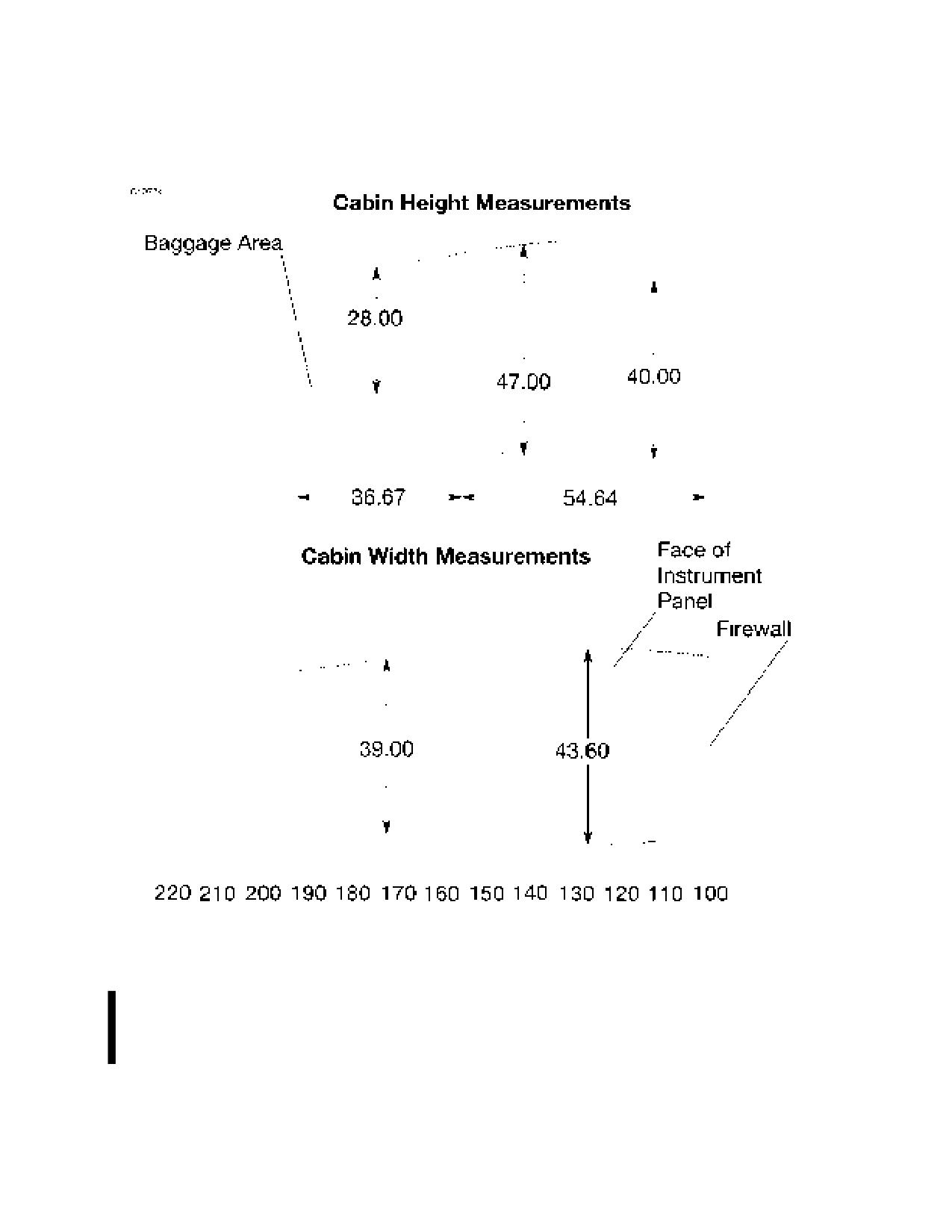
INTERNAL CABIN DIMENSIONS - U.S. UNITS
NOTE
• Maximum weight in the baggage compartment area is
50 pounds with a maximum floor loading of 8 pounds
per square foot.
• All dimensions shown are in inches.
Figure 4-7 (Sheet 1 of 2)
162PHUS-01
U.S.
4-25

SECTION 4
CESSNA
WEIGHT AND BALANCE/
MODEL 162
EQUIPMENT LIST
GARMIN G300
INTERNAL CABIN DIMENSIONS - METRIC UNITS
NOTE
• Maximum weight in the baggage compartment area is
22.68 kilograms with a maximum floor loading of 39.05
kilograms per square meter.
• All dimensions shown are in millimeters.
Figure 4-7 (Sheet 2)
4-26
U.S.
162PHUS-01

CESSNA
SECTION 4
MODEL 162
WEIGHT AND BALANCE/
GARMIN G300
EQUIPMENT LIST
CENTER OF GRAVITY MOMENT ENVELOPE - U.S.
Figure 4-8 (Sheet 1 of 2)
162PHUS-00
U.S.
4-27

SECTION 4
CESSNA
WEIGHT AND BALANCE/
MODEL 162
EQUIPMENT LIST
GARMIN G300
CENTER OF GRAVITY MOMENT ENVELOPE
METRIC UNITS
Figure 4-8 (Sheet 2)
4-28
U.S.
162PHUS-00

CESSNA
SECTION 4
MODEL 162
WEIGHT AND BALANCE/
GARMIN G300
EQUIPMENT LIST
CENTER OF GRAVITY LIMITS - U.S. UNITS
Figure 4-9 (Sheet 1 of 2)
162PHUS-00
U.S.
4-29

SECTION 4
CESSNA
WEIGHT AND BALANCE/
MODEL 162
EQUIPMENT LIST
GARMIN G300
CENTER OF GRAVITY LIMITS - METRIC UNITS
Figure 4-9 (Sheet 2)
4-30
U.S.
162PHUS-00
CESSNA
SECTION 5
MODEL 162
PERFORMANCE
GARMIN G300
PERFORMANCE
TABLE OF CONTENTS
Page
Introduction
5-3
Use of Performance Charts
5-3
Sample Problem
5-4
Takeoff
5-5
Cruise
5-6
Fuel Required
5-7
Landing
5-9
Demonstrated Operating Temperature
5-9
Airspeed Calibration
5-10
Stall Speeds At 1320 Pounds
5-11
Short Field Takeoff Distance At 1320 Pounds
5-12
Short Field Landing Distance At 1320 Pounds
5-13
Maximum Rate Of Climb At 1320 Pounds
5-14
Time, Fuel And Distance To Climb At 1320 Pounds
5-15
Cruise Performance
5-16
Temperature Conversion Chart
5-17
Crosswind Component
5-18
162PHUS-00
U.S.
5-1/5-2
CESSNA
SECTION 5
MODEL 162
PERFORMANCE
GARMIN G300
INTRODUCTION
Performance data charts on the following pages are presented so that
you may know what to expect from the airplane under various
conditions and to facilitate the planning of flights in detail with
reasonable accuracy. The data in the charts has been computed from
actual flight tests with the airplane and engine in good condition and
using average piloting techniques.
Fuel flow data for cruise is based on the recommended lean mixture
setting at all altitudes. Some indeterminate variables such as mixture
leaning technique, fuel metering characteristics, engine and propeller
condition, and air turbulence may account for variations of 10% or more
in range and endurance. Therefore, it is important to utilize all available
information to estimate the fuel required for the particular flight and to
flight plan in a conservative manner.
USE OF PERFORMANCE CHARTS
Performance data is presented in tabular form to illustrate the effect of
different variables. Sufficiently detailed information is provided in the
tables so that conservative values can be selected and used to
determine the particular performance figure with reasonable accuracy.
162PHUS-01
U.S.
5-3
SECTION 5
CESSNA
PERFORMANCE
MODEL 162
GARMIN G300
SAMPLE PROBLEM
The following sample flight problem utilizes information from the
various charts to determine the predicted performance data for a typical
flight. Assume the following information has already been determined:
AIRPLANE CONFIGURATION:
Takeoff weight
1320 Pounds
Usable fuel
24.0 Gallons
TAKEOFF CONDITIONS:
Field pressure altitude
1500 Feet
Temperature
28°C (16°C Above Standard)
Wind component along runway
14 Knot Head Wind
Field length
3500 Feet
CRUISE CONDITIONS:
Total distance
260 Nautical Miles
Pressure altitude
5500 Feet
Temperature
20°C (16°C Above Standard)
Expected wind enroute
10 Knot Head Wind
LANDING CONDITIONS:
Field pressure altitude
2000 Feet
Temperature
25°C
Field length
3000 Feet
(Continued Next Page)
5-4
U.S.
162PHUS-01
CESSNA
SECTION 5
MODEL 162
PERFORMANCE
GARMIN G300
SAMPLE PROBLEM (Continued)
TAKEOFF
The takeoff distance chart, Figure 5-3, should be consulted, keeping in
mind that distances shown are based on the short field technique.
Conservative distances can be established by reading the chart at the
next higher value of weight, altitude and temperature. For example, in
this particular sample problem, the takeoff distance information
presented for a weight of 1320 pounds, pressure altitude of 2000 feet
and a temperature of 30°C should be used and results in the following:
860 Feet
Ground roll
Total distance to clear a 50-foot obstacle
1495 Feet
These distances are well within the available takeoff field length.
However, a correction for the effect of wind may be made based on
information presented in the note section of the takeoff chart. The
correction for a 14 knot head wind is:
14 Knots
X 10% = 20% Decrease
7 Knots
This results in the following distances, corrected for wind:
Ground roll, zero wind
860 Feet
Decrease in ground roll (860 feet X 20%)
-172 Feet
Corrected ground roll
688 Feet
Total distance to clear a 50-foot obstacle, zero wind
1495 Feet
Decrease in total distance (1495 feet X 20%)
-299 Feet
Corrected total distance to clear 50-foot obstacle
1196 Feet
(Continued Next Page)
162PHUS-01
U.S.
5-5
SECTION 5
CESSNA
PERFORMANCE
MODEL 162
GARMIN G300
SAMPLE PROBLEM (Continued)
CRUISE
The cruising altitude should be selected based on a consideration of
trip length, winds aloft and the airplane's performance. A typical
cruising altitude and the expected wind enroute have been given for
this sample problem. However, the power setting selection for cruise
must be determined based on several considerations. These include
the cruise performance characteristics presented in Figure 5-7, the
maximum rate of climb chart presented in Figure 5-5, and the time, fuel
and distance to climb chart presented in Figure 5-6.
The cruise performance chart, Figure 5-7, is entered at 6000 feet
pressure altitude and 20°C above standard temperature. These values
most nearly correspond to the planned altitude and expected
temperature conditions. The engine speed chosen is 2750 RPM, which
results in the following:
Power
64%
True airspeed
108 Knots
Cruise fuel flow
6.0 GPH
(Continued Next Page)
5-6
U.S.
162PHUS-01
CESSNA
SECTION 5
MODEL 162
PERFORMANCE
GARMIN G300
SAMPLE PROBLEM (Continued)
FUEL REQUIRED
The total fuel requirement for the flight may be estimated using the
performance information in Figure 5-6 and Figure 5-7. For this sample
problem, the time, fuel and distance to climb may be determined from
Figure 5-6 for maximum rate of climb. The difference between the
values shown in the table for 5500 feet and 1500 feet results in the
following:
Time:
6.5 Minutes
Fuel:
0.9 Gallons
Distance:
6.0 Nautical Miles
These values are for a standard temperature and are sufficiently
accurate for most flight planning purposes. However, a further
correction for the effect of temperature may be made as noted on the
climb chart. The approximate effect of a nonstandard temperature is to
increase the time, fuel and distance by 10% for each 10°C above
standard temperature, due to the lower rate of climb. In this case,
assuming a temperature 16°C above standard the correction would be:
16°C
X 10% = 16% Increase
10°C
With this factor included, the fuel estimate would be calculated as
follows:
Fuel to climb, standard temperature
0.9 Gallons
Increase due to non-standard temperature (0.9 X 16%)
0.1 Gallons
Corrected fuel to climb
1.0 Gallons
Using a similar procedure for the distance to climb results in 7 nautical
miles.
The resultant cruise distance is:
Total distance
260 Nautical Miles
Climb distance
-7 Nautical Miles
Cruise distance
253 Nautical Miles
(Continued Next Page)
162PHUS-01
U.S.
5-7
SECTION 5
CESSNA
PERFORMANCE
MODEL 162
GARMIN G300
SAMPLE PROBLEM (Continued)
FUEL REQUIRED (Continued)
With an expected 10 knot head wind, the ground speed for cruise is
predicted to be:
108 Knots
-10 Knots
98 Knots
Therefore, the time required for the cruise portion of the trip is:
253 Nautical Miles = 2.6 Hours
98 Knots
The fuel required for cruise is:
2.6 hours 6.0 gallons/hour = 15.6 Gallons
A 30-minute reserve requires:
30
6.0 gallons/hour = 3.0 Gallons
60
The total estimated fuel required is as follows:
Engine start, taxi, and takeoff
0.6 Gallons
Climb
1.0
Gallons
Cruise
15.6
Gallons
Reserve
3.0 Gallons
Total fuel required
20.2
Gallons
Once the flight is underway, ground speed checks will provide a more
accurate basis for estimating the time enroute and the corresponding
fuel required to complete the trip with ample reserve.
(Continued Next Page)
5-8
U.S.
162PHUS-01
CESSNA
SECTION 5
MODEL 162
PERFORMANCE
GARMIN G300
SAMPLE PROBLEM (Continued)
LANDING
A procedure similar to takeoff should be used for estimating the landing
distance at the destination airport. Figure 5-4 presents landing distance
information for the short field technique. The distances corresponding
to 2000 feet and 30°C are as follows:
Ground roll
760 Feet
Total distance to clear a 50-foot obstacle
1485 Feet
A correction for the effect of wind may be made based on information
presented in the note section of the landing chart, using the same
procedure as outlined for takeoff.
DEMONSTRATED OPERATING TEMPERATURE
Satisfactory engine cooling has been demonstrated for this airplane
with an outside air temperature 23°C above standard. This is not to be
considered as an operating limitation. Reference should be made to
Section 2 for engine operating limitations.
162PHUS-01
U.S.
5-9
SECTION 5
CESSNA
PERFORMANCE
MODEL 162
GARMIN G300
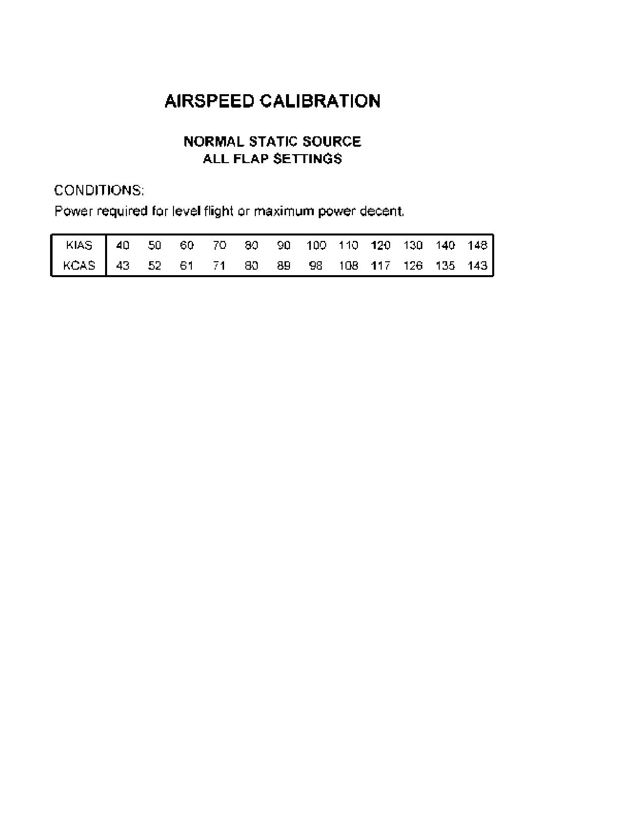
Figure 5-1
5-10
U.S.
162PHUS-00

CESSNA
SECTION 5
MODEL 162
PERFORMANCE
GARMIN G300
NOTE
• Altitude loss during a stall recovery may be as much as
250 feet.
• KIAS values are approximate.
Figure 5-2
162PHUS-00
U.S.
5-11

SECTION 5
CESSNA
PERFORMANCE
MODEL 162
GARMIN G300
Figure 5-3*
5-12
U.S.
162PHUS-01

CESSNA
SECTION 5
MODEL 162
PERFORMANCE
GARMIN G300
Figure 5-4*
162PHUS-01
U.S.
5-13
SECTION 5
CESSNA
PERFORMANCE
MODEL 162
GARMIN G300
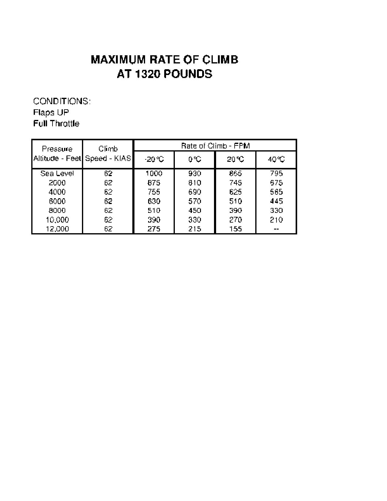
Figure 5-5*
5-14
U.S.
162PHUS-01

CESSNA
SECTION 5
MODEL 162
PERFORMANCE
GARMIN G300
Figure 5-6*
162PHUS-01
U.S.
5-15

SECTION 5
CESSNA
PERFORMANCE
MODEL 162
GARMIN G300
Figure 5-7*
5-16
U.S.
162PHUS-01

CESSNA
SECTION 5
MODEL 162
PERFORMANCE
GARMIN G300
TEMPERATURE CONVERSION CHART
Figure 5-8
162PHUS-00
U.S.
5-17

SECTION 5
CESSNA
PERFORMANCE
MODEL 162
GARMIN G300
CROSSWIND COMPONENT
NOTE
Maximum demonstrated crosswind velocity is 12 knots (not
a limitation).
Figure 5-9
5-18
U.S.
162PHUS-00
CESSNA
SECTION 6
MODEL 162
EMERGENCY PROCEDURES
GARMIN G300
EMERGENCY PROCEDURES
TABLE OF CONTENTS
Page
Introduction
6-5
Airspeeds For Emergency Operations
6-5
EMERGENCY PROCEDURES
6-6
ENGINE FAILURES AND MALFUNCTIONS
6-6
Engine Failure During Takeoff Roll
6-6
Engine Failure Immediately After Takeoff
6-6
Engine Failure During Flight (Restart Procedures)
6-7
Oil PSI Indicator In Red Band Range (Red Digits)
6-7
Carb °F Indicator In Yellow Band Range (Yellow Digits)
6-8
FORCED LANDINGS
6-9
Emergency Landing Without Engine Power
6-9
Precautionary Landing With Engine Power
6-10
Ditching
6-11
FIRES
6-12
During Start On Ground
6-12
Engine Fire In Flight
6-12
Electrical Fire or Cabin Fire In Flight
6-13
Wing Fire
6-14
ICING
6-15
Inadvertent Icing Encounter During Flight
6-15
ABNORMAL LANDINGS
6-17
Landing With Partial or No Flight Instrument Information
6-17
Landing With A Flat Main Tire
6-17
Landing With A Flat Nose Tire
6-18
Door Open in Flight
6-18
Landing With Door Open
6-18
(Continued Next Page)
162PHUS-00
U.S.
6-1
SECTION 6
CESSNA
EMERGENCY PROCEDURES
MODEL 162
GARMIN G300
TABLE OF CONTENTS (Continued)
Page
ELECTRICAL POWER SUPPLY SYSTEM MALFUNCTIONS . . . 6-19
Loss Of All Electrical Power (Except PFD)
6-19
LOW VOLTS Annunciator Comes On or Volts Indication Below
Green Band Range or Volts Less Than 12.5
6-20
Volts Indication Above Green Band Range or
Volts More Than 15
6-22
AIR DATA, ATTITUDE AND HEADING REFERENCE SYSTEM
(ADAHRS) FAILURE
6-23
Red X - PFD or MFD Indicators (Airspeed, Altitude, Attitude,
Horizontal Situation Indicator (HSI), or Engine Indicating
System (EIS))
6-23
PFD/MFD DISPLAY MALFUNCTION OR FAILURE
6-24
PFD or MFD Display Black (No Information)
6-24
PFD or MFD Display Information Not Updating
6-25
Electric Pitch Trim Failure
6-26
(Continued Next Page)
6-2
U.S.
162PHUS-00
CESSNA
SECTION 6
MODEL 162
EMERGENCY PROCEDURES
GARMIN G300
TABLE OF CONTENTS (Continued)
Page
AMPLIFIED EMERGENCY PROCEDURES
6-27
Engine Failure
6-27
Maximum Glide
6-28
Forced Landings
6-29
Landing Without Elevator Control
6-30
Fires
6-30
Emergency Operation In Clouds
6-31
Executing A 180° Turn In Clouds (ADAHRS FAILED)
6-31
Emergency Descent Through Clouds (ADAHRS FAILED)
6-32
Recovery From Spiral Dive In The Clouds (ADAHRS FAILED) .6-33
Inadvertent Flight Into Icing Conditions
6-34
Spins
6-35
Rough Engine Operation Or Loss Of Power
6-36
Carburetor Icing
6-36
Spark Plug Fouling
6-36
Magneto Malfunction
6-36
Idle Power Engine Roughness
6-37
Low Oil Pressure
6-37
Electrical Power Supply System Malfunctions
6-38
Excessive Rate Of Charge
6-38
Insufficient Rate Of Charge
6-39
Other Emergencies
6-40
Windshield Damage
6-40
G300 Failures
6-40
162PHUS-00
U.S.
6-3/6-4
CESSNA
SECTION 6
MODEL 162
EMERGENCY PROCEDURES
GARMIN G300
INTRODUCTION
Section 6 provides checklist and amplified procedures for coping with
emergencies that may occur. Emergencies caused by airplane or
engine malfunctions are extremely rare if proper preflight inspections
and maintenance are practiced. Enroute weather emergencies can be
minimized or eliminated by careful flight planning and good judgment
when unexpected weather is encountered. However, should an
emergency arise, the basic guidelines described in this section should
be considered and applied as necessary to correct the problem. In any
emergency situation, the most important task is continued control of the
airplane and maneuver to execute a successful landing.
Emergency procedures associated with optional or supplemental
equipment are found in Section 10, Supplements.
AIRSPEEDS FOR EMERGENCY OPERATIONS
ENGINE FAILURE AFTER TAKEOFF
Wing Flaps UP
70 KIAS
Wing Flaps 10° - FULL
65 KIAS
MANEUVERING SPEED
1320 POUNDS
89 KIAS
1200 POUNDS
85 KIAS
1100 POUNDS
80 KIAS
MAXIMUM GLIDE
70 KIAS
PRECAUTIONARY LANDING WITH ENGINE POWER
60 KIAS
LANDING WITHOUT ENGINE POWER
Wing Flaps UP
70 KIAS
Wing Flaps 10° - FULL
65 KIAS
162PHUS-02
U.S.
6-5
SECTION 6
CESSNA
EMERGENCY PROCEDURES
MODEL 162
GARMIN G300
EMERGENCY PROCEDURES
Procedures in the Emergency Procedures Checklist portion of this
section shown in bold faced type are immediate action items which
should be committed to memory.
ENGINE FAILURES AND MALFUNCTIONS
ENGINE FAILURE DURING TAKEOFF ROLL
1. THROTTLE Control - IDLE (pull full out)
2. Brakes - APPLY
3. Wing Flaps - RETRACT
4. MIXTURE Control - IDLE CUTOFF (pull full out)
5. MAGNETOS Switch - OFF
6. MASTER Switch (ALT and BAT) - OFF
ENGINE FAILURE IMMEDIATELY AFTER TAKEOFF
1. Airspeed - 70 KIAS - Flaps UP
65 KIAS - Flaps 10° - FULL
2. MIXTURE Control - IDLE CUTOFF (pull full out)
3. FUEL SHUTOFF Valve - OFF (pull full out)
4. MAGNETOS Switch - OFF
5. Wing Flaps - AS REQUIRED (FULL recommended)
6. MASTER Switch (ALT and BAT) - OFF (when landing is
assured)
7. Land - STRAIGHT AHEAD
8. Doors - UNLATCH (just prior to touchdown)
NOTE
Both cabin doors are equipped with gas struts and should
open automatically when unlatched. Delaying opening until
just prior to touchdown will reduce cabin buffeting and wind
noise. Non-emergency flight with doors open is prohibited.
(Continued Next Page)
6-6
U.S.
162PHUS-00
CESSNA
SECTION 6
MODEL 162
EMERGENCY PROCEDURES
GARMIN G300
ENGINE FAILURES AND MALFUNCTIONS (Continued)
ENGINE FAILURE DURING FLIGHT (Restart Procedures)
1. Airspeed - 70 KIAS (best glide speed)
2. THROTTLE Control - IDLE (pull full out)
3. CARB HEAT Control Knob - ON (pull full out)
4. FUEL SHUTOFF Valve - ON (push full in)
5. MIXTURE Control - RICH (if restart has not occurred)
6. PRIMER - IN and LOCKED (if installed)
7. MAGNETOS Switch - BOTH (or START if propeller is stopped)
NOTE
If
the propeller is windmilling, engine will restart
automatically within a few seconds. If propeller has stopped
(possible at low speeds), turn MAGNETOS switch to
START, advance throttle slowly from idle and lean the
mixture from full rich as required to obtain smooth
operation.
OIL PSI INDICATOR IN RED BAND RANGE (RED DIGITS)
1. OIL °F - CHECK
IF OIL °F ABOVE GREEN BAND RANGE OR OIL °F RISING
(engine failure immanent)
2. Throttle Control - REDUCE POWER IMMEDIATELY
3. Airspeed - 70 KIAS (best glide speed)
4. Land as soon as possible (refer to EMERGENCY LANDING
WITHOUT ENGINE POWER)
IF OIL °F WITHIN GREEN BAND RANGE
2. OIL °F - MONITOR
3. OIL PSI - MONITOR
4. Land as soon as practical (nearest suitable airport
recommended)
(Continued Next Page)
162PHUS-01
U.S.
6-7
SECTION 6
CESSNA
EMERGENCY PROCEDURES
MODEL 162
GARMIN G300
ENGINE FAILURES AND MALFUNCTIONS (Continued)
CARB °F INDICATOR IN YELLOW BAND RANGE
(YELLOW DIGITS)
1. ENGINE - MONITOR FOR ROUGHNESS AND/OR RPM LOSS
NOTE
Carb °F indicator in yellow band range indicates
temperatures may support carb icing formation.
IF ENGINE ROUGHNESS AND/OR RPM LOSS IS DETECTED
(CARB °F IN YELLOW BAND RANGE)
2. CARB HEAT Control Knob - ON (pull full out)
3. THROTTLE Control - FULL (push full in)
4. MIXTURE Control - LEAN (as required)
5. CARB °F Indicator - CHECK
IF ENGINE ROUGHNESS CONTINUES
6. CARB °F Indicator - MONITOR
7. ALTITUDE - CONSIDER CHANGE (to warmer or drier air mass
if terrain permits)
8. Land as soon as practical.
IF ENGINE ROUGHNESS IS NOT DETECTED (CARB °F ABOVE
YELLOW BAND RANGE)
6. CARB °F Indicator - MONITOR
7. CARB HEAT Control Knob - AS REQUIRED
8. Continue flight as normal.
6-8
U.S.
162PHUS-01
CESSNA
SECTION 6
MODEL 162
EMERGENCY PROCEDURES
GARMIN G300
FORCED LANDINGS
EMERGENCY LANDING WITHOUT ENGINE POWER
1. Seats and Seat Belts - SECURE
2. Airspeed -70 KIAS - Flaps UP
65 KIAS - Flaps 10° - FULL
3. MIXTURE Control - IDLE CUTOFF (pull full out)
4. FUEL SHUTOFF Valve - OFF (pull full out)
5. Radio - ALERT ATC or TRANSMIT MAYDAY ON 121.5 MHZ,
(give location, intentions and SQUAWK 7700)
6. MAGNETOS Switch - OFF
7. Wing Flaps - AS REQUIRED (FULL recommended)
8. MASTER Switch (ALT and BAT) - OFF (when landing is
assured)
9. ELT - ACTIVATE
10. Doors - UNLATCH (just prior to touchdown)
NOTE
Both cabin doors are equipped with gas struts and should
open automatically when unlatched. Delaying opening until
just prior to touchdown will reduce cabin buffeting and wind
noise. Non-emergency flight with doors open is prohibited.
11. Touchdown - SLIGHTLY TAIL LOW
12. Brakes - APPLY HEAVILY
(Continued Next Page)
162PHUS-00
U.S.
6-9
SECTION 6
CESSNA
EMERGENCY PROCEDURES
MODEL 162
GARMIN G300
FORCED LANDINGS (Continued)
PRECAUTIONARY LANDING WITH ENGINE POWER
1. Seats and Seat Belts - SECURE
2. Airspeed - 70 KIAS
3. Wing Flaps - 10° or 25°
4. Radio - ALERT ATC or TRANSMIT MAYDAY ON 121.5 MHZ,
(give location, intentions and SQUAWK 7700)
5. Selected Field - FLY OVER (noting terrain and obstructions)
6. Wing Flaps - FULL (on final approach)
7. Airspeed - 60 KIAS
8. MASTER Switch (ALT and BAT) - OFF (when landing assured)
9. ELT - ACTIVATE
10. Doors - UNLATCH (Just prior to touchdown)
NOTE
Both cabin doors are equipped with gas struts and should
open automatically when unlatched. Delaying opening until
just prior to touchdown will reduce cabin buffeting and wind
noise. Non-emergency flight with doors open is prohibited.
11. Touchdown - SLIGHTLY TAIL LOW
12. MIXTURE Control - IDLE CUTOFF (pull full out)
13. MAGNETOS Switch - OFF
14. Brakes - APPLY HEAVILY
6-10
U.S.
162PHUS-00
CESSNA
SECTION 6
MODEL 162
EMERGENCY PROCEDURES
GARMIN G300
FORCED LANDINGS (Continued)
DITCHING
1. Radio - TRANSMIT MAYDAY on 121.5 MHz, (give location,
intentions and SQUAWK 7700)
2. Heavy Objects (in baggage area) - SECURE OR JETTISON (if
possible)
3. Seats and Seat Belts - SECURE
4. Wing Flaps - 25° or FULL
5. Power - ESTABLISH 300 FT/MIN DESCENT AT 60 KIAS
NOTE
If no power is available, approach at 70 KIAS with Flaps UP
or at 65 KIAS with Flaps 10°.
6. Approach - High Winds, Heavy Seas - INTO THE WIND
Light Winds, Heavy Swells
- PARALLEL TO
SWELLS
7. ELT - ACTIVATE
8. Doors - UNLATCH (just prior to touchdown)
NOTE
Both cabin doors are equipped with gas struts and should
open automatically when unlatched. Delaying opening until
just prior to touchdown will reduce cabin buffeting and wind
noise. Non-emergency flight with doors open is prohibited.
9. Touchdown - LEVEL ATTITUDE AT ESTABLISHED 300 FT/MIN
DESCENT
10. Face - CUSHION AT TOUCHDOWN (with folded coat)
11. Airplane - EVACUATE THROUGH CABIN DOORS
162PHUS-00
U.S.
6-11
SECTION 6
CESSNA
EMERGENCY PROCEDURES
MODEL 162
GARMIN G300
FIRES
DURING START ON GROUND
1. MAGNETOS Switch - START (continue cranking to start the
engine)
IF ENGINE STARTS
2. Power - 1800 RPM (for a few minutes)
3. Engine - SHUTDOWN (inspect for damage)
IF ENGINE FAILS TO START
2. THROTTLE Control - FULL (push full in)
3. MIXTURE Control - IDLE CUTOFF (pull full out)
4. MAGNETOS Switch - START (continue cranking)
5. FUEL SHUTOFF Valve - OFF (pull full out)
6. MAGNETOS Switch - OFF
7. MASTER Switch (ALT and BAT) - OFF
8. Engine - SECURE
9. Parking Brake - RELEASE
10. Fire Extinguisher - OBTAIN (have ground attendants obtain if not
installed)
11. Airplane - EVACUATE
12. Fire - EXTINGUISH (using fire extinguisher, wool blanket, or dirt)
13. Fire Damage
- INSPECT (repair or replace damaged
components and/or wiring before conducting another flight)
ENGINE FIRE IN FLIGHT
1. MIXTURE Control - IDLE CUTOFF (pull full out)
2. FUEL SHUTOFF Valve - OFF (pull full out)
3. MASTER Switch (ALT Only) - OFF
4. Cabin Vents - OPEN (as needed)
5. CABIN HEAT Control Knob - OFF (push full in) (to avoid drafts)
6. Airspeed - 85 KIAS (If fire is not extinguished, increase glide
speed to find an airspeed, within airspeed limitations, which will
provide an incombustible mixture)
7. Forced Landing - EXECUTE (refer to EMERGENCY LANDING
WITHOUT ENGINE POWER)
(Continued Next Page)
6-12
U.S.
162PHUS-00
CESSNA
SECTION 6
MODEL 162
EMERGENCY PROCEDURES
GARMIN G300
FIRES (Continued)
ELECTRICAL FIRE OR CABIN FIRE IN FLIGHT
1. MASTER Switch (ALT and BAT) - OFF
WARNING
OUTSIDE VISUAL REFERENCE MUST BE USED TO
MAINTAIN SITUATIONAL AWARENESS. ALL FLIGHT
INSTRUMENTS, RADIOS, AND PITCH TRIM WILL BE
INOPERATIVE WHEN MASTER SWITCH IS TURNED
OFF.
2. Cabin Vents - CLOSED (to avoid drafts)
3. CABIN HEAT Control Knob - OFF (push full in) (to avoid
drafts)
4. Fire Extinguisher - ACTIVATE (if available)
5. AVN MASTER Switch - OFF
6. All Other Switches (except MAGNETOS switch) - OFF
IF FIRE HAS NOT BEEN EXTINGUISHED
7. MASTER Switch (ALT and BAT) - ON
8. Rapid Descent - EXECUTE (Perform sideslip to rapidly lose
altitude and shorten exposure time).
9. AVN MASTER Switch - ON
10. Radio - ALERT ATC or TRANSMIT MAYDAY ON 121.5 MHZ,
(give location, intentions and SQUAWK 7700)
11. Forced Landing
- EXECUTE (refer to PRECAUTIONARY
LANDING WITH ENGINE POWER)
NOTE
The G300 self-test and ADAHRS alignment may take
several minutes to establish thus delaying display of flight
instrument data. It may be necessary to execute landing
without airspeed or altitude information.
(Continued Next Page)
162PHUS-03
U.S.
6-13
SECTION 6
CESSNA
EMERGENCY PROCEDURES
MODEL 162
GARMIN G300
FIRES (Continued)
ELECTRICAL FIRE OR CABIN FIRE IN FLIGHT (Continued)
IF FIRE HAS BEEN EXTINGUISHED AND ELECTRICAL POWER
IS NECESSARY FOR CONTINUED FLIGHT TO NEAREST
SUITABLE AIRPORT OR LANDING AREA
WARNING
AFTER THE FIRE EXTINGUISHER HAS BEEN USED,
MAKE SURE THAT THE FIRE IS EXTINGUISHED
BEFORE EXTERIOR AIR IS USED TO REMOVE SMOKE
FROM THE CABIN.
7. Cabin Vents
- OPEN (when sure that fire is completely
extinguished)
8. CABIN HEAT Control Knob - ON (pull full out) (when sure that fire
is completely extinguished)
9. Circuit Breakers - CHECK (for OPEN circuit(s), do not reset)
10.MASTER Switch (ALT and BAT) - ON
11.AVN MASTER Switch - ON
12.Land the airplane as soon as possible to inspect for damage.
WING FIRE
1. LDG Light Switch - OFF
2. NAV Light Switch - OFF
3. STROBE Light Switch - OFF
NOTE
Perform a sideslip to keep the flames away from the fuel
tank and cabin.
4.
Land as soon as possible.
6-14
U.S.
162PHUS-00
CESSNA
SECTION 6
MODEL 162
EMERGENCY PROCEDURES
GARMIN G300
ICING
INADVERTENT ICING ENCOUNTER DURING FLIGHT
1. Turn back or change altitude to exit icing conditions.
Consider lateral or vertical flight path reversal to return to last
"known good" flight conditions (to obtain an outside air
temperature that is less conducive to icing). Maintain VFR flight.
WARNING
FAILURE TO ACT QUICKLY MAY RESULT IN AN
UNRECOVERABLE ICING ENCOUNTER.
2. CABIN HEAT Control Knob - ON (pull full out)
3. A/P DISC/CWS
- PRESS (if installed) (verify autopilot
disengages and aural alert is heard)
WARNING
DO NOT ENGAGE AUTOPILOT WITH VISIBLE ICE ON
AIRFRAME OR AFTER ENCOUNTERING ICING
CONDITIONS.
4. Watch for signs of induction air filter icing and apply carburetor
heat as required. Monitoring the G300 Carb °F Indicator may
assist early detection. A loss of engine RPM could be caused by
carburetor ice or ice blocking the air intake filter. Adjust the
throttle as necessary to hold engine RPM. Adjust mixture as
necessary for any change in power settings or if carburetor heat
is used continuously.
5. Watch for ice accretion on pitot tube and signs of pitot-static
icing. Airspeed and altimeter indications may become
unreliable.
a. Attitude and Heading information will remain reliable in
event of airspeed and altimeter failure. Use attitude indicator
to monitor pitch and bank.
b. Reference GS (ground speed) in conjunction with GPS
derived wind information to determine an approximate
airspeed.
(Continued Next Page)
162PHUS-03
U.S.
6-15
SECTION 6
CESSNA
EMERGENCY PROCEDURES
MODEL 162
GARMIN G300
ICING (Continued)
INADVERTENT ICING ENCOUNTER DURING FLIGHT
(Continued)
c. Reference GPS ALTITUDE on MFD INFO page (if installed)
or select G300 TERRAIN Profile page. GPS Altitude is
provided by the white arrowhead on the left side of the
TERRAIN Profile display.
d. Navigate using Heading Strip, Lateral Deviation, and GPS
moving map (GPS moving map and TERRAIN Profile can
not be displayed at the same time).
NOTE
GPS information is not as accurate as barometric data but
will provide an approximate value for comparison to pitot-
static instruments or a back-up if barometric instruments
become unreliable.
6. Plan a landing at the nearest airport. With an extremely rapid ice
build-up, select a suitable off airport landing site.
7. With an ice accumulation of 0.25 inch (6.35mm) or more on the
wing leading edges, be prepared for significantly higher power
requirements, higher approach and stall speeds, and a longer
landing roll. Gently pitch and yaw the airplane periodically to
keep ice bridging on the controls to a minimum.
8. Leave wing flaps retracted. With a severe ice build-up on the
horizontal tail, the change in wing wake airflow direction caused
by wing flap extension could result in a loss of elevator
effectiveness.
9. Perform a landing approach using a forward slip, if necessary,
for improved visibility.
10. Approach at 65 to 70 KIAS (estimated 70 KIAS. if using GPS)
depending upon the amount of ice accumulation.
11. Perform landing in level attitude.
12. Missed approaches should be avoided whenever possible
because of severely reduced climb capability.
6-16
U.S.
162PHUS-00
CESSNA
SECTION 6
MODEL 162
EMERGENCY PROCEDURES
GARMIN G300
ABNORMAL LANDINGS
LANDING WITH PARTIAL OR NO FLIGHT INSTRUMENT
INFORMATION
1. Transponder - Select Pressure Alt display using FUNC button
(ADAHRS may be providing altitude information to transponder).
2. Selected Field - FLY OVER (noting terrain, obstructions, and
any visual cues that may be used for speed references (i.e.
traffic on nearby highway, etc))
3. Approach - NORMAL
4. Wing Flaps - AS REQUIRED (FULL recommended)
5. Speed - Use best pilot judgment and experience to reference
speed cues such as flap extension forces, slipstream sounds,
etc. Stall warning horn will function and provide approximately 5
knot stall warning.
6. Touchdown - NORMAL
7. Directional Control - MAINTAIN
NOTE
Without accurate speed information, landing may be made
at faster than normal speeds. Gently apply brakes while
continuing to “fly” the airplane during roll-out. Loss of
directional control may result from locked brakes and
skidding tires due to over braking.
LANDING WITH A FLAT MAIN TIRE
1. Approach - NORMAL
2. Wing Flaps - FULL
3. Touchdown - GOOD MAIN TIRE FIRST (hold airplane off flat tire
as long as possible with aileron control)
4. Directional Control - MAINTAIN (using rudder and brake on
good wheel as required)
162PHUS-01
U.S.
6-17
SECTION 6
CESSNA
EMERGENCY PROCEDURES
MODEL 162
GARMIN G300
ABNORMAL LANDINGS (Continued)
LANDING WITH A FLAT NOSE TIRE
1. Approach - NORMAL (choose longest runway if possible)
2. Wing Flaps - AS REQUIRED
a.
65 to 70 KIAS - Flaps UP - 10°
b.
Below 65 KIAS - Flaps 10° - FULL
3. Touchdown - ON MAINS (tail slightly low)
4. Elevator - continue stick to full aft as airplane slows (hold
nosewheel off the ground as long as possible)
5. When nosewheel touches down, maintain full up elevator as
airplane slows to stop.
6. Directional Control
- MAINTAIN (using full rudder control)
Attempt to limit differential braking.
7. Braking - Use brakes only as needed to lessen chance of prop
strike. Rolling drag of the flat nose tire will increase braking
effect.
DOOR OPEN IN FLIGHT
WARNING
INTENTIONAL FLIGHT WITH DOOR(S) OPEN IS
PROHIBITED.
1. CABIN DOOR - LEAVE OPEN (do not attempt to close)
2. THROTTLE Control - REDUCE (as necessary)
3. Airspeed - 80 KIAS (or less)
4. Seat Belts - CHECK (verify secure and tight)
5. Cabin - CHECK (stow loose materials)
6. Land as soon as practical.
LANDING WITH DOOR OPEN
1. Wing Flaps - AS REQUIRED
a.
65 to 70 KIAS - Flaps UP - 10°
b.
Below 65 KIAS - Flaps 10° - FULL
2. Landing Approach - NORMAL (limit sideslip angle if possible)
3. Touchdown - NORMAL
6-18
U.S.
162PHUS-01
CESSNA
SECTION 6
MODEL 162
EMERGENCY PROCEDURES
GARMIN G300
ELECTRICAL
POWER
SUPPLY
SYSTEM
MALFUNCTIONS
LOSS OF ALL ELECTRICAL POWER (EXCEPT PFD)
1. MAIN CB RESET Switch - PRESS MOMENTARILY
IF ELECTRICAL POWER RESUMES NORMAL OPERATION
2. Continue flight and land as soon as practical.
IF ELECTRICAL POWER REMAINS INOPERATIVE (EXCEPT
PFD)
2. Land as soon as possible.
NOTE
The PFD will be operating on the secondary battery only.
The secondary battery is not a back-up battery. It is
included in the electrical system to limit display presentation
issues that might arise during the voltage drop which
occurs during engine start. In good condition, the
secondary battery may provide 5 to 10 minutes of PFD
operation.
3. Prepare for total loss of electrical power and PFD. Refer to
ABNORMAL LANDINGS, LANDING WITH PARTIAL OR NO
FLIGHT INSTRUMENT INFORMATION
(Continued Next Page)
162PHUS-00
U.S.
6-19
SECTION 6
CESSNA
EMERGENCY PROCEDURES
MODEL 162
GARMIN G300
ELECTRICAL
POWER
SUPPLY
SYSTEM
MALFUNCTIONS (Continued)
LOW VOLTS ANNUNCIATOR COMES ON OR VOLTS
INDICATION BELOW GREEN BAND RANGE OR VOLTS
LESS THAN 12.5
NOTE
Volts indication below the green band range or less than
12.5 volts may occur during low RPM conditions with an
electrical load on the system such as during a low RPM
taxi. Under these conditions, the volts indication will
increase into the green band range (12.5 - 15.0 volts) at
higher RPM. The master switch need not be recycled since
an overvoltage condition has not occurred to deactivate the
alternator system.
1. AVN MASTER Switch - OFF
NOTE
Radio, Transponder, Pitch Trim, and options (MFD,
Autopilot, and PS Intercom), if installed, will be inoperative
with AVN MASTER Switch in the OFF position.
2. START/ALT Circuit Breaker - CHECK IN (if open, reset (close)
circuit breaker. If circuit breaker opens again, do not reset)
3. MASTER Switch (ALT Only) - OFF
4. MASTER Switch (ALT Only) - ON
5. MAIN CB RESET Switch - PRESS MOMENTARILY
6. VOLTS - CHECK 13.5 Volts (minimum)
7. AMPS - CHECK CHARGING (positive)
8. AVN MASTER Switch - ON (only if VOLTS are 12.5 and AMPS
are charging)
6-20
U.S.
162PHUS-01
CESSNA
SECTION 6
MODEL 162
EMERGENCY PROCEDURES
GARMIN G300
ELECTRICAL
POWER
SUPPLY
SYSTEM
MALFUNCTIONS (Continued)
IF VOLTS INDICATION REMAINS BELOW GREEN BAND RANGE
OR LESS THAN 12.5 VOLTS
9. MASTER Switch (ALT Only) - OFF
10. Electrical Load - REDUCE as follows:
a. LDG Light Switch - OFF (use as required for landing)
b. NAV Light Switch - OFF
c. STROBE Light Switch - OFF
d. AVN MASTER Switch - OFF
NOTE
Radio, Transponder, Pitch Trim, and options (MFD,
Autopilot, and PS Intercom), if installed, will be inoperative
with AVN MASTER Switch in the OFF position.
11. Land as soon as practical.
NOTE
A fully charged battery in good condition should provide
power under reduced load for 30 minutes.
(Continued Next Page)
162PHUS-00
U.S.
6-21
SECTION 6
CESSNA
EMERGENCY PROCEDURES
MODEL 162
GARMIN G300
ELECTRICAL
POWER
SUPPLY
SYSTEM
MALFUNCTIONS (Continued)
VOLTS INDICATION ABOVE GREEN BAND RANGE OR
VOLTS MORE THAN 15
1. MASTER Switch (ALT Only) - OFF
2. Electrical Load - REDUCE as follows:
a. LDG Light Switch - OFF (use as required for landing)
b. NAV Light Switch - OFF
c. STROBE Light Switch - OFF
d. AVN MASTER Switch - OFF
NOTE
Radio, Transponder, Pitch Trim, and options (MFD,
Autopilot, and PS Intercom), if installed, will be inoperative
with AVN MASTER - OFF.
3. Land as soon as practical.
NOTE
A fully charged battery in good condition should provide
power under reduced load for 30 minutes.
6-22
U.S.
162PHUS-00
CESSNA
SECTION 6
MODEL 162
EMERGENCY PROCEDURES
GARMIN G300
AIR DATA, ATTITUDE AND HEADING REFERENCE
SYSTEM (ADAHRS) FAILURE
RED X
- PFD OR MFD INDICATORS (AIRSPEED,
ALTITUDE, ATTITUDE, HORIZONTAL SITUTATION
INDICATOR (HSI), OR ENGINE INDICATING SYSTEM (EIS))
1.
ADAHRS Circuit Breaker - CHECK IN
a. If open, reset (close) circuit breaker. If circuit breaker opens
again, do not reset.
b. If closed, pull (open) ADAHRS Circuit Breaker, and pull
(open) SEC PWR Circuit Breaker (overhead Panel Light will
go off) then reset (close) both circuit breakers
2.
Affected Indicator (other than EIS) - RED-X STILL DISPLAYED
a. Reference GS (ground speed) in conjunction with GPS
derived wind information to determine an approximate
airspeed.
b. Select COMPASS ARC from G300 MAP SET-UP for
approximate GPS derived heading information or monitor
magnetic compass (if installed).
c. Reference GPS ALTITUDE on TERRAIN PROFILE page
(GPS altitude is the white arrowhead on left side) or MFD
INFO page (if installed) for approximate altitude.
d. Navigate using pilotage and GPS moving map if available.
e. Land as soon as possible.
3.
EIS Engine Indicating System - RED-X STILL DISPLAYED
a. If only the EIS is RED X (no other PFD or MFD RED X is
present), continue monitoring. Non-emergency full throttle
operation should be limited to prevent engine overspeed or
exceeding temperatures. Descents should be made at idle
with carburetor heat applied.
b. Land as soon as possible.
4.
Affected Indicator - RED-X HAS CLEARED (indicator normal)
5.
Land as soon as practical.
162PHUS-01
U.S.
6-23
SECTION 6
CESSNA
EMERGENCY PROCEDURES
MODEL 162
GARMIN G300
PFD/MFD DISPLAY MALFUNCTION OR FAILURE
PFD OR MFD DISPLAY BLACK (NO INFORMATION)
1. PANEL LIGHTS Control Knob - FULL BRIGHT (full clockwise
rotation)
2. PFD/MFD Circuit Breaker - CHECK IN
a. If open, reset (close) circuit breaker. If circuit breaker opens
again, do not reset.
b. If closed, pull (open) PFD/MFD Circuit Breaker, and pull
(open) SEC PWR Circuit Breaker (overhead Panel Light will
go off) then reset (close) both circuit breakers
3. Affected Display - Continued BLACK Screen (No information
displayed) - Use other display (if installed).
a. Transponder - Select Pressure Alt display using FUNC
button (ADAHRS may be providing altitude information to
transponder)
b. Navigate using pilotage and magnetic compass (if installed)
to nearest suitable landing site.
c. Land as soon as possible. Refer to LANDING WITH
PARTIAL OR NO INSTRUMENTATION INFORMATION.
4. Affected Display - NORMAL SCREEN
a. Land as soon as practical.
(Continued Next Page)
6-24
U.S.
162PHUS-03
CESSNA
SECTION 6
MODEL 162
EMERGENCY PROCEDURES
GARMIN G300
PFD/MFD DISPLAY MALFUNCTION OR FAILURE
(Continued)
PFD OR MFD DISPLAY INFORMATION NOT UPDATING
1. Pull (open) the following circuit breakers:
a. ADAHRS Circuit Breaker - OPEN
b. PFD/MFD Circuit Breaker - OPEN
c. SEC PWR Circuit Breaker - OPEN (overhead panel light will
go off)
2. Reset (close) all three circuit breakers
a. ADAHRS Circuit Breaker - CLOSE
b. PFD/MFD Circuit Breaker - CLOSE
c. SEC PWR Circuit Breaker - CLOSE
3. Affected Display(s) - NOT UPDATING (use other display (if
installed).
a. Transponder - Select Pressure Altitude display using FUNC
button (ADAHRS may be providing altitude information to
transponder).
b. Navigate using pilotage and magnetic compass (if installed)
to nearest suitable landing site.
c. Land as soon as possible. Refer to LANDING WITH
PARTIAL OR NO INSTRUMENTATION INFORMATION
4. Affected Display - NORMAL SCREEN
a. Land as soon as practical.
162PHUS-01
U.S.
6-25
SECTION 6
CESSNA
EMERGENCY PROCEDURES
MODEL 162
GARMIN G300
ELECTRIC PITCH TRIM FAILURE
1. AVN MASTER Switch - VERIFY ON
2. TRIM/AP Circuit Breaker - CHECK IN
a. If open, reset (close) circuit breaker. If circuit breaker opens
again, do not reset.
b. If closed, pull (open) TRIM/AP Circuit Breaker, then reset
(close) the circuit breaker.
ELECTRIC
PITCH
TRIM
SYSTEM
REMAINS
INOPERATIVE
3. Reduce pitch control forces by changing speed or flap
configuration (within airspeed limitations).
4. CRUISE - Consider range reduction and destination change if
cruise speed is reduced by flap speed limitations.
5. APPROACH
- Establish stabilized approach using normal
speeds is preferred. This may include change of destination for
longer runway.
6. LANDING WITH FAILED TRIM - Consider making Flaps UP
landing if pitch control force increases uncomfortably when
lowering landing flaps.
7. Land as soon as practical.
ELECTRIC PITCH TRIM SYSTEM RESUMES NORMAL
OPERATION
3. Land as soon as practical.
6-26
U.S.
162PHUS-01
CESSNA
SECTION 6
MODEL 162
EMERGENCY PROCEDURES
GARMIN G300
AMPLIFIED EMERGENCY PROCEDURES
The following Amplified Emergency Procedures provide additional
information beyond that in the Emergency Procedures Checklists
portion of this section. These procedures also include information not
readily adaptable to a checklist format, and material to which a pilot
could not be expected to refer in resolution of a specific emergency.
This information should be reviewed in detail prior to flying the airplane,
as well as reviewed on a regular basis to keep pilot’s knowledge of
procedures fresh.
ENGINE FAILURE
If an engine failure occurs during the takeoff roll, stop the airplane on
the remaining runway. Those extra items on the checklist will provide
added safety after a failure of this type.
If an engine failure occurs immediately after takeoff, in most cases, the
landing should be planned straight ahead with only small changes in
direction to avoid obstructions. Altitude and airspeed are seldom
sufficient to execute the 180° gliding turn necessary to return to the
runway. The checklist procedures assume that adequate time exists to
secure the fuel and ignition systems prior to touchdown.
After an engine failure in flight, the most important task is to continue
flying the airplane. The best glide speed, as shown in Figure 6-1,
should be established as quickly as possible. While gliding toward a
suitable landing area, an effort should be made to identify the cause of
the failure. If time permits, an engine restart should be attempted as
shown in the checklist. If the engine cannot be restarted, a forced
landing without power must be completed.
162PHUS-00
U.S.
6-27

SECTION 6
CESSNA
EMERGENCY PROCEDURES
MODEL 162
GARMIN G300
MAXIMUM GLIDE
Figure 6-1
6-28
U.S.
162PHUS-00
CESSNA
SECTION 6
MODEL 162
EMERGENCY PROCEDURES
GARMIN G300
FORCED LANDINGS
If all attempts to restart the engine fail and a forced landing is imminent,
select a suitable field and prepare for the landing as discussed under
the Emergency Landing Without Engine Power checklist. Transmit
Mayday message on 121.5 MHz giving location, intentions and squawk
7700.
Before attempting an off airport landing with engine power available,
one should fly over the landing area at a safe, but low altitude, to
inspect the terrain for obstructions and surface conditions, proceeding
as discussed in the Precautionary Landing With Engine Power
checklist.
Prepare for ditching by securing or jettisoning heavy objects located in
the baggage area and collect folded coats for protection of occupants'
face at touchdown. Transmit Mayday messages on 121.5 MHz giving
location, intentions and squawk 7700. Avoid a landing flare because of
the difficulty in judging height over a water surface. The checklist
assumes the availability of power to make a precautionary water
landing. If power is not available, use of the airspeeds noted with
minimum flap extension will provide a more favorable attitude for a
power off ditching.
In a forced landing situation, DO NOT turn off the MASTER switch (BAT
side) or AVN MASTER switch before the landing is assured unless
specifically instructed by the emergency procedure checklist.
Premature deactivation of these switches will disable all airplane
electrical systems. Note however there are specific emergency
procedures (such as Electrical Fire) which do require the MASTER
switch (ALT side) to be turned off. Exercise caution when performing
these procedures to ensure that only the ALT side is selected off.
Before completing a forced landing, especially in remote and
mountainous areas, activate the ELT by pressing the ELT ON switch
located on the right instrument panel. For complete information on ELT
operation, refer to Section 10, Supplements.
162PHUS-00
U.S.
6-29
SECTION 6
CESSNA
EMERGENCY PROCEDURES
MODEL 162
GARMIN G300
LANDING WITHOUT ELEVATOR CONTROL
Using throttle and electric elevator trim switch, trim for horizontal flight
at 55-60 KIAS with flaps 25° selected. Then do not change the
elevator trim or the flap setting; control the glide angle by making
small changes in power.
Power changes should be made slowly and smoothly. The electric
elevator trim is powerful. It is best to bump, or pulse, the trim switch to
make changes. Holding the trim switch can result in over trimming and
may start a Pilot Induced Oscillation (PIO) condition resulting in chasing
the trim. If this occurs, it is best to let the airplane stabilize then start
again by just bumping the trim switch.
When in the flare, the elevator trim switch should be pulsed aft toward
the full-nose-up position at the same time slowly reducing power so that
the airplane is rotated to a slightly nose-above-the-horizon attitude for
touchdown. During the landing flare or round-out, the nose will come
down when power is reduced and the airplane may touch down on the
nosewheel before the main wheels. Maintain directional control and
close the throttle at touchdown.
FIRES
Although engine fires are extremely rare in flight, if a fire is
encountered, the steps of the appropriate checklist should be followed.
After completion of the checklist procedure, execute a forced landing.
Do not attempt to restart the engine. The first sign of an electrical fire is
usually the smell of burning insulation. The checklist procedure for
electrical fires calls for electrical power to be turned off. All flight
instruments and navigation will be lost at this time. The checklist
procedure should result in the elimination of the fire. When the fire is
extinguished, electrical power may be turned on to those systems not
involved. Navigation and flight information, if unaffected, should be
reposted to instruments within
1-2 minutes. If the fire is not
extinguished, a rapid descent should be initiated and the electrical
system turned back on. This may provide airspeed and altitude data in
preparation for a forced landing.
6-30
U.S.
162PHUS-00
CESSNA
SECTION 6
MODEL 162
EMERGENCY PROCEDURES
GARMIN G300
EMERGENCY OPERATION IN CLOUDS
The Model 162 Skycatcher is not equipped or certified for IFR flight.
The following instructions assume that the pilot is not very proficient at
instrument flying and is flying the airplane without the autopilot
engaged (if installed). The autopilot (if installed) will not operate if the
ADAHRS unit fails.
EXECUTING A 180° TURN IN CLOUDS (ADAHRS FAILED)
Upon inadvertently entering the clouds, an immediate turn to reverse
course and return to VFR conditions should be made. With ADAHRS
FAILED, magnetometer (magnetic) heading information is not
available. The G300 map display should be configured with the
COMPASS ARC from the MAP SET-UP menu. The COMPASS ARC
will provide GPS derived heading information on the moving map
display. GPS derived heading information is not as accurate as
magnetic heading; it will provide a means of situational awareness and
the moving map can provide navigation. Other GPS information such
as track (TRK), etc. are also available with a functioning G300 system.
Refer to the G300 Pilot's Guide.
If the optional magnetic compass is installed, the magnetic compass
maybe used in place of the G300 compass arc. The magnetic compass
will be subject to normal magnetic compass A.N.D.S. variations during
maneuvering.
(Continued Next Page)
162PHUS-03
U.S.
6-31
SECTION 6
CESSNA
EMERGENCY PROCEDURES
MODEL 162
GARMIN G300
EMERGENCY OPERATION IN CLOUDS (Continued)
EMERGENCY DESCENT THROUGH CLOUDS (ADAHRS
FAILED)
When returning to VFR flight after a 180° turn is not practical, a descent
through the clouds to VFR conditions below may be appropriate. If
possible, obtain an ATC assistance and clearance for an emergency
descent through the clouds.
Before descending into the clouds, prepare for a stabilized descent as
follows:
1. Reference optional magnetic compass (if installed) or select
G300 map with COMPASS ARC from MAP SET-UP menu for
GPS derived approximate heading information on moving map
display.
2. If MFD is installed, select the INFO page and reference the GPS
ALTITUDE. GPS ALTITUDE is not the same as barometric
altitude but it will give an altitude approximation.
3. TERRAIN - Select G300 TERRAIN - ON. If RED terrain warning
is issued, apply full power and climb at 58 KIAS estimated. Stall
warning will provide approximate 5 knot stall warning margin.
4. Monitor Ground Speed (GS) - GPS derived GS in combination
with GPS derived wind vector information will allow
approximation of airspeed.
5. MIXTURE Control - RICH (push full in)
6. CARB HEAT Control Knob - ON (pull full out)
7. THROTTLE Control - REDUCE (1700 - 1800 RPM)
8. Approximate Airspeed - 70 - 75 Knots (estimate airspeed from
GS and wind vector data)
9. Elevator Trim - ADJUST (as required)
10. Maintain descent - procedure will provide 500 TO 800 FT/MIN
descent rate.
11. Upon breaking out of clouds, resume normal cruising flight.
(Continued Next Page)
6-32
U.S.
162PHUS-01
CESSNA
SECTION 6
MODEL 162
EMERGENCY PROCEDURES
GARMIN G300
EMERGENCY OPERATION IN CLOUDS (Continued)
RECOVERY FROM SPIRAL DIVE IN THE CLOUDS
(ADAHRS FAILED)
ADAHRS FAILURE
If a spiral is entered while in the clouds, continue as follows:
1. THROTTLE Control - IDLE (pull full out)
2. Remove feet from rudder pedals.
3. Stop turn by carefully leveling the wings using aileron control
while referencing COMPASS ARC or optional magnetic
compass (if installed) and moving map for heading and turn
information.
4. Cautiously apply elevator back pressure to slowly reduce
airspeed to approximately 70 KIAS. Monitor speed and do not
reduce airspeed below 70 KIAS. Slowly advance throttle to
approximate 1700-1800 RPM as speed reaches 70-75 Knots.
5. Elevator Trim - ADJUST (maintain 70-75 KIAS glide speed)
6. Use aileron control to maintain wings level and constant
heading.
7. CARB HEAT Control Knob - ON (pull full out)
8. Clear engine occasionally, but avoid using enough power to
disturb the trimmed glide.
9. Resume EMERGENCY DESCENT THROUGH THE CLOUDS
procedure.
10. Upon breaking out of clouds, resume normal cruising flight.
162PHUS-01
U.S.
6-33
SECTION 6
CESSNA
EMERGENCY PROCEDURES
MODEL 162
GARMIN G300
INADVERTENT FLIGHT INTO ICING CONDITIONS
Flight into icing conditions is prohibited and extremely dangerous.
While an inadvertent encounter with these conditions can be resolved
using the checklist procedures, the best action is to turn back or
change altitude immediately to escape icing conditions.
Watch for signs of pitot-static icing and ice accretion on the unheated
pitot tube. If airspeed and altimeter indications become unreliable, GPS
derived flight information can provide approximate values for back-up.
GPS derived ground speed (GS) and GPS ALTITUDE on the MFD
INFO page (if installed) may be used for comparison to barometric
instruments. GPS ALTITUDE information also replaces barometric
altitude in the TERRAIN Page PROFILE window (indicated by a white
arrowhead) when the ADAHRS is inoperative.
In the event of an icing encounter, an unexplained loss of engine power
could be caused by carburetor ice or ice blocking the air intake filter.
Should this happen, apply full carburetor heat and adjust throttle to
obtain maximum RPM. In some instances, the throttle may need to be
reduced for maximum power. The mixture should then be adjusted, as
required, to obtain maximum RPM. The G300 CARB °F indicator
should be monitored during carb heat application to ensure carb
temperature rises. Refer to the CARBUETOR ICING AMPLIFIED
EMERGENCY PROCEDURE section.
Maximum cabin heat should be applied, by pulling the CABIN HEAT
Control Knob to the full out position, in an attempt to clear ice from the
windshield. GPS moving map navigation may assist if ice creates a loss
of visibility. If available, select G300 TERRAIN - ON for additional
altitude and obstacle awareness during reduced visibility. Use of a
forward slip can improve forward and over-the-nose landing visibility
inhibited by windshield ice. FLAPS should NOT be used for landing if
airframe ice is present.
The autopilot, if installed, should be disconnected at first indication of
airframe icing and remain disconnected after any icing encounter due
to the possibility of unseen residual ice on the airframe.
6-34
U.S.
162PHUS-00
CESSNA
SECTION 6
MODEL 162
EMERGENCY PROCEDURES
GARMIN G300
SPINS
Should an inadvertent spin occur, the following recovery procedure
should be used:
1. IMMEDIATELY RETARD THROTTLE TO IDLE POSITION.
2. PLACE AILERONS IN NEUTRAL POSITION.
3. APPLY AND HOLD FULL RUDDER OPPOSITE TO THE
DIRECTION OF ROTATION.
4. JUST AFTER THE RUDDER REACHES THE STOP, MOVE
CONTROL BRISKLY FORWARD FAR ENOUGH TO BREAK
THE STALL. Full down elevator may be required at aft
center of gravity loadings to assure optimum recoveries.
5. HOLD THESE CONTROL INPUTS UNTIL ROTATION STOPS.
Premature relaxation of the control inputs may extend the
recovery.
6. AS ROTATION STOPS, NEUTRALIZE RUDDER, WINGS
LEVEL, FLAPS UP AND MAKE A SMOOTH RECOVERY
FROM THE RESULTING DIVE. AVOID OVERSTRESSING
AND OVERSPEEDING THE AIRFRAME.
NOTE
If the rate of the spin makes determining the direction of
rotation difficult, the magenta turn rate trend vector in the
heading strip over the PFD Attitude Indicator will show the
rate and direction of the turn. The HSI compass card will
rotate in the opposite direction. Hold full rudder opposite the
direction of the turn indicated by the turn rate trend vector.
162PHUS-03
U.S.
6-35
SECTION 6
CESSNA
EMERGENCY PROCEDURES
MODEL 162
GARMIN G300
ROUGH ENGINE OPERATION OR LOSS OF POWER
CARBURETOR ICING
A gradual loss of RPM and eventual engine roughness may result from
the formation of carburetor ice. To clear the ice, apply full throttle and
pull the CARB HEAT control knob full out until the engine runs
smoothly; then reduce carburetor heat and readjust throttle as
necessary. Monitor the G300 CARB °F indicator to verify the carburetor
temperature rises out of the amber caution range. If conditions require
the continued use of carburetor heat in cruise flight, use the minimum
amount of heat necessary to prevent ice from forming and lean the
mixture for smoothest engine operation. The G300 CARB °F indicator
provides advisory information but does not replace the need to monitor
engine condition and adjust carburetor heat or mixture as needed for
safe engine performance.
SPARK PLUG FOULING
A slight engine roughness in flight may be caused by one or more spark
plugs becoming fouled by carbon or lead deposits. This may be verified
by turning the MAGNETOS switch momentarily from BOTH to either L
or R position. An obvious power loss in single magneto operation is
evidence of spark plug or magneto trouble. Leaning the mixture to the
recommended lean setting for cruising flight may resolve a spark plug
fouling issue. If the problem does not clear up in several minutes,
determine if a richer mixture setting will produce smoother operation. If
not, proceed to the nearest airport for repairs using the BOTH position
of the MAGNETOS switch unless extreme roughness makes the use of
a single MAGNETO position necessary.
MAGNETO MALFUNCTION
Sudden engine roughness or misfiring is usually a sign of a magneto
problem. Changing the MAGNETOS switch from BOTH to the L and R
switch positions will identify which magneto is malfunctioning. Select
different power settings and enrichen the mixture to determine if
continued operation on BOTH magnetos is possible. If not, change to
the good magneto and continue to the nearest airport for repairs.
(Continued Next Page)
6-36
U.S.
162PHUS-00
CESSNA
SECTION 6
MODEL 162
EMERGENCY PROCEDURES
GARMIN G300
ROUGH ENGINE OPERATION OR LOSS OF POWER
(Continued)
IDLE POWER ENGINE ROUGHNESS
An excessively rich idle fuel flow may cause low speed engine
roughness during flight. During most in-flight low engine speeds (power
off stalls, approach to landing, etc.), the mixture control is normally in
the full-rich position. However, to improve engine roughness during low
engine speeds while in flight, you should rotate the vernier mixture
control to lean of fuel mixture. You may also have to lean the fuel
mixture if this low engine speed results in power loss and you need to
restart the engine during flight. In all cases, you should land the
airplane at the nearest airport for repairs if low speed engine roughness
requires you to adjust the fuel mixture control to improve engine
operation.
LOW OIL PRESSURE
If the low oil pressure indicator (OIL PSI) turns red, and oil temperature
indicator (OIL °F) remains normal, it is possible that the oil pressure
sending unit or relief valve is malfunctioning. Land at the nearest airport
to determine the source of the problem.
If a total loss of oil pressure and a rise in oil temperature occur at about
the same time, it could mean that the engine is about to fail. Reduce
power immediately and select a field suitable for a forced landing. Use
only the minimum power necessary to reach the landing site.
162PHUS-00
U.S.
6-37
SECTION 6
CESSNA
EMERGENCY PROCEDURES
MODEL 162
GARMIN G300
ELECTRICAL
POWER
SUPPLY
SYSTEM
MALFUNCTIONS
Malfunctions in the electrical power supply system can be detected
through regular monitoring of the main battery ammeter (AMPS) and
the electrical bus voltmeter (VOLTS); however, the cause of these
malfunctions is usually difficult to determine. A broken alternator shaft,
excessive brush wear, or an internal wiring issue is most likely the
cause of alternator failures, although other factors could cause the
problem. Problems of this nature constitute an electrical emergency
and should be dealt with immediately. Electrical power malfunctions
usually fall into two categories: excessive rate of charge and insufficient
rate of charge. The following paragraphs describe the recommended
remedy for each situation.
EXCESSIVE RATE OF CHARGE
After engine starting and heavy electrical usage at low engine speeds,
such as extended taxiing, the battery condition may be low enough to
accept above normal charging during the initial part of a flight.
However, after thirty minutes of cruising flight, the main battery
ammeter (AMPS) should be indicating less than 5 amps of charging (+)
current. If the charging current remains above this value on a long
flight, the battery electrolyte could overheat and evaporate.
Electronic components in the electrical system can be adversely
affected by higher than normal voltage. The built-in overvoltage
protection circuit will automatically disconnect the alternator if the
charge voltage increases to more than 16.5 volts. If the overvoltage
sensor circuit does not operate correctly, as shown by voltage more
than 16.5 volts on the electrical bus voltmeter, the MASTER switch ALT
section should be set to the OFF position. Unnecessary electrical
equipment should be de-energized and the flight terminated as soon as
practical.
If excessive rate of charge is indicated but the electrical bus voltmeter
indicates less than 15 volts, no immediate action is required. Continue
monitoring and land as soon as practical.
(Continued Next Page)
6-38
U.S.
162PHUS-00
CESSNA
SECTION 6
MODEL 162
EMERGENCY PROCEDURES
GARMIN G300
ELECTRICAL
POWER
SUPPLY
SYSTEM
MALFUNCTIONS (Continued)
INSUFFICIENT RATE OF CHARGE
When the overvoltage circuit, or other fault, opens the alternator
(START/ALT) circuit breaker and de-energizes the alternator, a
discharge (-) current will be shown on the main battery ammeter
(AMPS) and the red LOW VOLTS annunciator will be displayed on the
PFD. The Alternator Internal Control Unit (AICU) can de-energize the
alternator due to minor disturbances in the electrical system, resulting
in a nuisance opening of the START/ALT circuit breaker. If this
happens, an attempt should be made to energize the alternator system.
To energize the alternator system
1. MASTER Switch (ALT Only) - OFF
2. START/ALT Circuit Breaker - CHECK IN
3. MASTER Switch (ALT Only) - ON
If the problem was a minor AICU disturbance in the electrical system,
normal main battery charging will start. A charge (+) current will be
shown on the main battery ammeter (AMPS) and the LOW VOLTS
annunciator will go off.
If the red LOW VOLTS annunciator is displayed and a discharge (-)
current is still shown on the AMPS Indicator, there is an alternator
system problem. Do not repeat steps to energize the alternator system.
Decrease the electrical load on the battery by de-energizing
nonessential electrical equipment and avionics (consider exterior lights
and radio equipment) because the battery can supply the electrical
system for only a short time. Reduce electrical load as soon as possible
to extend the life of the battery for landing. Land as soon as practical.
162PHUS-00
U.S.
6-39
SECTION 6
CESSNA
EMERGENCY PROCEDURES
MODEL 162
GARMIN G300
OTHER EMERGENCIES
WINDSHIELD DAMAGE
If a bird strike or other incident should damage the windshield in flight to
the point of creating an opening, a significant loss in performance may
be expected. Decrease airspeed and set power as necessary to
maintain best glide speed (70 KIAS) to minimize stress on windshield
and airframe structure. If airplane performance or other adverse
conditions prevent landing at an airport, prepare for an off airport
landing in accordance with the PRECAUTIONARY LANDING WITH
ENGINE POWER or DITCHING checklists.
G300 FAILURES
The Garmin G300 system provides all flight and engine instrument
information via the Air Data Attitude and Heading Reference System
(ADAHRS) unit. Individual sensors within the ADAHRS unit provide air
and flight data information as well as serve as the central gateway for
the engine data displayed on the Primary Flight Display (PFD) and
optional Multi-Function Display (MFD).
Failure of the ADAHRS unit or the individual sensors may leave only
GPS derived flight data for situational awareness and navigation. The
pilot should be thoroughly familiar with the G300 operation, page and
information location, and methods of accessing the GPS flight data
before beginning any flight in the Model
162 Skycatcher. It is
recommended that the pilot step through each of the G300 emergency
procedures in the Emergency Procedures Checklist for familiarization
before operating the aircraft.
Failure of the G300 PFD display will cause an automatic reversion of
the PFD display to the MFD display (if installed). Failure of the PFD
without an installed MFD display will leave the pilot to rely largely on
external cues for pilotage and navigation. The Emergency Procedures
Checklist contains suggestions for managing a successful PFD failure
and landing. It is recommended that the pilot become familiar with this
checklist before operating the airplane.
6-40
U.S.
162PHUS-01
CESSNA
SECTION 7
MODEL 162
NORMAL PROCEDURES
GARMIN G300
NORMAL PROCEDURES
TABLE OF CONTENTS
Page
Introduction
7-3
Airspeeds For Normal Operation
7-3
NORMAL PROCEDURES
7-4
Preflight Inspection
7-4
Cabin
7-5
Left Wing
7-6
Left Wing Leading Edge
7-8
Left Wing Trailing Edge
7-8
Empennage
7-8
Right Wing Trailing Edge
7-9
Right Wing
7-9
Nose
7-11
Before Starting Engine
7-13
Starting Engine (With Battery)
7-13
Starting Engine (With External Power)
7-15
Taxi Check
7-17
Before Takeoff
7-18
Takeoff
7-19
Normal Takeoff
7-19
Short Field Takeoff
7-19
Enroute Climb
7-20
Cruise
7-20
Descent
7-20
Before Landing
7-20
Landing
7-21
Normal Landing
7-21
Short Field Landing
7-21
Balked Landing
7-21
After Landing
7-22
Securing Airplane
7-22
(Continued Next Page)
162PHUS-03
U.S.
7-1
SECTION 7
CESSNA
NORMAL PROCEDURES
MODEL 162
GARMIN G300
TABLE OF CONTENTS (Continued)
Page
AMPLIFIED NORMAL PROCEDURES
7-23
Preflight Inspection
7-23
Before Starting Engine
7-25
Starting Engine
7-25
Recommended Starter Duty Cycle
7-26
Leaning For Ground Operations
7-27
Taxiing
7-27
Before Takeoff
7-30
Warm Up
7-30
Magneto Check
7-30
Alternator Check
7-31
Electric Elevator Trim
7-31
Takeoff
7-31
Power Check
7-31
Wing Flap Settings
7-32
Crosswind Takeoff
7-33
Enroute Climb
7-33
Cruise
7-34
Leaning Without Exhaust Gas Temperature (EGT) Indicator . . 7-35
Leaning With Exhaust Gas Temperature (EGT) Indicator
7-36
Fuel Savings Procedures For Flight Training Operations
7-38
Stalls
7-39
Descent
7-39
Landing
7-40
Normal Landing
7-40
Short Field Landing
7-40
Crosswind Landing
7-41
Balked Landing
7-41
High Winds Operations
7-41
Cold Weather Operations
7-42
Starting
7-43
Winterization Kit
7-45
Hot Weather Operations
7-45
Noise Characteristics
7-46
7-2
U.S.
162PHUS-03
CESSNA
SECTION 7
MODEL 162
NORMAL PROCEDURES
GARMIN G300
INTRODUCTION
Section 7 provides procedures and amplified instructions for normal
operations using standard and optional equipment. Normal procedures
associated with more complex optional equipment can be found in
Section 10, Supplements.
AIRSPEEDS FOR NORMAL OPERATION
Unless otherwise noted, the following speeds are based on a maximum
weight of 1320 pounds and may be used for any lesser weight.
TAKEOFF
Normal Climb
65 - 75 KIAS
Short Field Takeoff, Flaps 10°, Speed at 50 Feet
55 KIAS
ENROUTE CLIMB, FLAPS UP
Normal, Sea Level
65 - 75 KIAS
Best Rate of Climb
62 KIAS
Best Angle of Climb
57 KIAS
LANDING APPROACH
Normal Approach, Flaps UP
60 - 70 KIAS
Normal Approach, Flaps FULL
55 - 65 KIAS
Short Field Approach, Flaps FULL
50 KIAS
BALKED LANDING
Maximum Power, Flaps 25°
50 KIAS
MAXIMUM
RECOMMENDED
TURBULENT
AIR
PENETRATION SPEED
1320 POUNDS
89 KIAS
1200 POUNDS
85 KIAS
1100 POUNDS
80 KIAS
MAXIMUM DEMONSTRATED CROSSWIND VELOCITY
Takeoff or Landing
12 KNOTS
MAXIMUM RECOMMENDED WIND VELOCITY
All Operations
22 KNOTS
162PHUS-03
U.S.
7-3

SECTION 7
CESSNA
NORMAL PROCEDURES
MODEL 162
GARMIN G300
NORMAL PROCEDURES
PREFLIGHT INSPECTION
NOTE
Visually check airplane for general condition during walk-
around inspection. Airplane should be parked in a normal
ground attitude (refer to Figure 1-1) to make sure that fuel
drain valves allow for accurate sampling. In cold weather,
remove even small accumulations of frost, ice or snow from
wing, tail and control surfaces. Also, make sure that control
surfaces contain no internal accumulations of ice or debris.
If a night flight is planned, check operation of all lights, and
make sure a flashlight is available.
Figure 7-1
7-4
U.S.
162PHUS-00
CESSNA
SECTION 7
MODEL 162
NORMAL PROCEDURES
GARMIN G300
PREFLIGHT INSPECTION (Continued)
1 CABIN
1. Pilot's Operating Handbook - AS DESIRED
2. Garmin G300 Pilot’s Guide - AS DESIRED
3. Pilot’s Checklist - ACCESSIBLE TO PILOT
4. Parking Brake - SET
a. Brakes - Apply
b. PARKING BRAKE Control Knob - ON (pull full out)
5. Control Stick Lock - REMOVE
6. Wing Flaps - UP
7. Fuel Quantity Indicators - CHECK (L and R)
WARNING
• TAKEOFF IS PROHIBITED WITH LESS THAN ¼
TANK OF FUEL.
MIN
GRND
MARKING ON FUEL INDICATOR
T.O.
• WHEN THE MASTER SWITCH IS ON, USING AN
EXTERNAL POWER SOURCE, OR MANUALLY
ROTATING THE PROPELLER, TREAT THE
PROPELLER AS IF THE MAGNETOS SWITCH WERE
ON. DO NOT STAND, NOR ALLOW ANYONE ELSE
TO STAND, WITHIN THE ARC OF THE PROPELLER
SINCE A LOOSE OR BROKEN WIRE, OR A
COMPONENT MALFUNCTION, COULD CAUSE THE
ENGINE TO START.
8. MAGNETOS Switch - OFF
9. MASTER Switch (ALT and BAT) - ON
10. AVN MASTER Switch - ON
11. Primary Flight Display (PFD) - CHECK (verify PFD is ON and
software current)
12. Multifunction Flight Display (MFD) - CHECK (if installed) (verify
MFD is ON)
13. PFD ADAHRS Test and MFD SELF TEST - COMPLETE (verify
no red X’s shown)
(Continued Next Page)
162PHUS-03
U.S.
7-5
SECTION 7
CESSNA
NORMAL PROCEDURES
MODEL 162
GARMIN G300
PREFLIGHT INSPECTION (Continued)
1 CABIN (Continued)
14. LOW VOLTS Annunciator
- CHECK (verify annunciator is
shown)
NOTE
LOW VOLTS Annunciator will only be shown if battery
voltage is less than 12.5 volts. Verify battery voltage on
PFD/MFD ENG page.
15. Elevator Trim Control - T/O POSITION
16. Avionics Cooling Fan - CHECK (verify fan is operational)
17. Airplane Weight and Balance - CHECKED and ENTERED
18. AVN MASTER Switch - OFF
19. MASTER Switch (ALT and BAT) - OFF
20. Fire Extinguisher - CHECK (if installed) (verify gage pointer in
green arc)
2 LEFT WING
1. Cabin Door - CHECK (security and condition)
2. Main Wheel Tire
- CHECK (proper inflation and general
condition (weather checks, tread depth and wear, etc.))
3. Brake Line - CHECK (security and condition)
4. Wheel Fairings - CHECK (security and condition) (if installed)
5. Fresh Air Vent - CHECK (blockage)
6. Fuel Quantity - CHECK VISUALLY (for desired level)
WARNING
TAKEOFF IS PROHIBITED WITH LESS THAN ¼ TANK
OF FUEL.
MIN
GRND
MARKING ON FUEL INDICATOR
T.O.
7. Fuel Filler Cap - SECURE and VENT CLEAR
(Continued Next Page)
7-6
U.S.
162PHUS-00
CESSNA
SECTION 7
MODEL 162
NORMAL PROCEDURES
GARMIN G300
PREFLIGHT INSPECTION (Continued)
2 LEFT WING (Continued)
8. Fuel Tank Sump Quick Drain Valves - DRAIN
Drain at least a cupful of fuel (using sampler cup) from each
sump location to check for water, sediment, and proper fuel
grade before each flight and after each refueling. If water is
observed, take further samples until clear and then gently rock
wings and lower tail to the ground to move any additional
contaminants to the sampling points. Take repeated samples
from all fuel drain points until all contamination has been
removed. If contaminants are still present, refer to WARNING
below and do not fly airplane.
NOTE
Collect all sampled fuel in a safe container. Dispose of the
sampled fuel so that it does not cause a nuisance, hazard,
or damage to the environment.
WARNING
IF, AFTER REPEATED SAMPLING, EVIDENCE OF
CONTAMINATION STILL EXISTS, THE AIRPLANE
SHOULD NOT BE FLOWN. TANKS SHOULD BE
DRAINED AND SYSTEM PURGED BY QUALIFIED
MAINTENANCE PERSONNEL. ALL EVIDENCE OF
CONTAMINATION MUST BE REMOVED BEFORE
FURTHER FLIGHT.
(Continued Next Page)
162PHUS-00
U.S.
7-7
SECTION 7
CESSNA
NORMAL PROCEDURES
MODEL 162
GARMIN G300
PREFLIGHT INSPECTION (Continued)
3 LEFT WING Leading Edge
1. Fuel Tank Vent Opening - CHECK (blockage)
2. Wing Tiedown - DISCONNECT (check security and condition)
3. Pitot Tube Cover - REMOVE (check for pitot blockage)
4. Landing Light - CHECK (condition, operation and cleanliness of
cover)
5. Strobe/Nav Light - CHECK (condition, operation and cleanliness
of cover)
4 LEFT WING Trailing Edge
1. Aileron - CHECK (freedom of movement and security)
NOTE
Check for proper aileron movement by pushing the aileron
up from the neutral (or faired with the flaps in the Flaps UP
position) and returning the aileron back to the neutral or
faired position. Pushing down on the aileron may create an
over-centered condition requiring re-centering of the cockpit
control stick.
2. Flap - DEFLECT and CHECK (flap/aileron cables, up-spring
tension and general condition)
3. Com Antenna and OAT Temp Probe - CHECK (security of
attachment and general condition)
5 EMPENNAGE
1. Rudder Gust Lock (if installed) - REMOVE
2. Control Surfaces - CHECK (freedom of movement and security)
3. Elevator Trim Tab - CHECK (security) (verify tab is faired with
elevator and trim indicator in T/O position)
4. Tail Tiedown - DISCONNECT
(Continued Next Page)
7-8
U.S.
162PHUS-01
CESSNA
SECTION 7
MODEL 162
NORMAL PROCEDURES
GARMIN G300
PREFLIGHT INSPECTION (Continued)
6 RIGHT WING Trailing Edge
1. ELT and GPS Antennas - CHECK (security of attachment and
general condition)
2. Flap - DEFLECT and CHECK (flap/aileron cables, up-spring
tension and general condition)
3. Aileron - CHECK (freedom of movement and security)
NOTE
Check for proper aileron movement by pushing the aileron
up from the neutral (or faired with the flaps in the Flaps UP
position and returning the aileron back to the neutral or
faired position. Pushing down on the aileron may create an
over-centered condition requiring re-centering of the cockpit
control stick.
7 RIGHT WING
1. Strobe/Nav Light - CHECK (condition, operation and cleanliness
of cover)
2. Wing Tiedown - DISCONNECT (check security and condition)
3. Stall Warning Opening - CHECK (blockage)
NOTE
To check the system, place a clean handkerchief over the
vent opening and apply suction; a sound from the warning
horn will confirm system operation.
4. Fuel Quantity - CHECK VISUALLY (for desired level)
WARNING
TAKEOFF IS PROHIBITED WITH LESS THAN ¼ TANK
OF FUEL.
MIN
GRND
MARKING ON FUEL INDICATOR
T.O.
(Continued Next Page)
162PHUS-01
U.S.
7-9
SECTION 7
CESSNA
NORMAL PROCEDURES
MODEL 162
GARMIN G300
PREFLIGHT INSPECTION (Continued)
7 RIGHT WING (Continued)
5. Fuel Filler Cap - SECURE and VENT CLEAR
6. Main Wheel Tire
- CHECK (proper inflation and general
condition (weather checks, tread depth and wear, etc.))
7. Brake Line - CHECK (security and condition)
8. Wheel Fairings - CHECK (security and condition) (if installed)
9. Fuel Tank Sump Quick Drain Valves - DRAIN
Drain at least a cupful of fuel (using sampler cup) from each
sump location to check for water, sediment, and proper fuel
grade before each flight and after each refueling. If water is
observed, take further samples until clear and then gently rock
wings and lower tail to the ground to move any additional
contaminants to the sampling points. Take repeated samples
from all fuel drain points until all contamination has been
removed. If contaminants are still present, refer to WARNING
below and do not fly airplane.
NOTE
Collect all sampled fuel in a safe container. Dispose of the
sampled fuel so that it does not cause a nuisance, hazard
or damage to the environment.
WARNING
IF, AFTER REPEATED SAMPLING, EVIDENCE OF
CONTAMINATION STILL EXISTS, THE AIRPLANE
SHOULD NOT BE FLOWN. TANKS SHOULD BE
DRAINED AND SYSTEM PURGED BY QUALIFIED
MAINTENANCE PERSONNEL. ALL EVIDENCE OF
CONTAMINATION MUST BE REMOVED BEFORE
FURTHER FLIGHT.
10. Cabin Door - CHECK (security, condition and make sure door is
unlocked prior to flight)
WARNING
CABIN DOORS CANNOT BE UNLOCKED FROM INSIDE
THE AIRPLANE.
11. Fresh Air Vent - CHECK (blockage)
(Continued Next Page)
7-10
U.S.
162PHUS-03
CESSNA
SECTION 7
MODEL 162
NORMAL PROCEDURES
GARMIN G300
PREFLIGHT INSPECTION (Continued)
8 NOSE
1. Engine Cooling Air Inlets - CHECK (clear of obstructions)
2. Propeller and Spinner - CHECK (for nicks and security)
3. Air Filter - CHECK (for condition and blockage by dust or other
foreign matter)
4. Nosewheel Strut and Tire - CHECK (strut and general condition
of tire (weather checks, tread depth and wear, etc.))
5. Nosewheel Fairing
- CHECK (security and condition) (if
installed)
6. Engine Exhaust Outlet - CHECK (security and condition)
7. Engine Oil Dipstick/Filler Cap:
a. Oil level - CHECK
b. Dipstick/filler cap - SECURE (lever horizontal and facing aft)
NOTE
Do not operate with less than 3.5 quarts. Fill to 5 quarts
for extended flight.
8. Fuel Strainer Quick Drain Valve - DRAIN (bottom left side of
engine cowling)
Drain at least a cupful of fuel (using sampler cup) from valve to
check for water, sediment, and proper fuel grade before each
flight and after each refueling. If water is observed, take further
samples until clear and then gently rock wings and lower tail to
the ground to move any additional contaminants to the sampling
points. Take repeated samples from all fuel drain points,
including the fuel strainer and fuel sump valve, until all
contamination has been removed. If contaminants are still
present, refer to WARNING below and do not fly the airplane.
NOTE
Collect all sampled fuel in a safe container. Dispose of the
sampled fuel so that it does not cause a nuisance, hazard,
or damage to the environment.
(Continued Next Page)
162PHUS-00
U.S.
7-11