Military reference books and manuals (2009-2023, Volume 5) - page 41
SW820-AP-MMI-010
REVISION 15
27 MARCH 2009
CHAPTER 1
WEAPON
GOVERNING
SYSTEM
REPORT
MEDIA
DIRECTIVE
PURPOSE OF REPORT
UGM-109-1
PRODUCT
Standard
NAVSEAINST
Report receipt of defective
UGM-109-2
QUALITY
Form 368
4855.7
AURs or material.
RGM-109-2
DEFICIENCY
RGM-109-4
REPORT
(QDR)
UGM-109-1
REPORT OF
Standard
NAVMATINST
Report shipping and
UGM-109-2
ITEM DIS-
Form 364
4355.7
packaging discrepancies
RGM-109-2
CREPANCY
RGM-109-4
(ROID)
UGM-109-1
SUBMARINE
SWFTR
For use by Organizational
UGM-109-2
WEAPON
Form
Level Activities under
FIELD
the cognizance of
TROUBLE
the Submarine Type
REPORT
Commanders (TYCOMs)
(SWFTR)
to report damaged, faulty,
or failed equipment,
ineffective documentation,
routine requests for
technical assistance,
corrective maintenance
and/or results of PMS
accomplishment for
UGM-109C/D/E AURs
and related equipment.
UGM-109-1
TECHNICAL
NAVSEA
NAVSEAINST
Report errors, omissions
UGM-109-2
MANUAL
Form
4160.3
or discrepancies or
RGM-109-2
DEFICIENCY/
4160/1
recommend changes
RGM-109-4
EVALUATION
to basic manuals.
REPORT
(TMDER)
UGM-109-1
HAZARDOUS
Message
OPNAVINST
Report accident or incident
UGM-109-2
INCIDENT
5102.1 for Navy/
with material loss or
RGM-109-2
REPORT
CMPINST 5102.1
damage to any variant
RGM-109-4
for contractor
creating hazard/potential
hazard.
148
SW820-AP-MMI-010
REVISION 15
27 MARCH 2009
CHAPTER 1
WEAPON
GOVERNING
SYSTEM
REPORT
MEDIA
DIRECTIVE
PURPOSE OF REPORT
RGM-109-4
CANISTER
OP-
NAVSEAINST
Report Mk 14 Canister
SHORE AC-
NAVINST
4790.6
preventive and
TIVITY MAIN-
Form
unscheduled maintenance
TENANCE
4790/5(2A)
and defects
DATA SUM-
MARY
RGM-109-4
CANISTER/
NAVSEA
NAVSEAINST
Report Mk 14 Canister
MISSILE CON-
Form
4790.6
configuration changes to
FIGURATION
4790/5(2B)
include encan/decan
SUMMARY
SHORE AC-
TIVITY MAIN-
TENANCE
DATA SUM-
MARY
149
SW820-AP-MMI-010
REVISION 15
27 MARCH 2009
CHAPTER 1
Table 1-6. Common Descriptive Data
ITEM
DESCRIPTION
Engine:
Designation
F107-WR-400(a) or F107-WR-402(b)
Type
Turbofan
Thrust.
600 lb
Rocket Motor Assembly:(a)
Designation
Mk 106 Mod 0
Type
Single-chamber, fixed nozzle
Propellant
Arcadene 228G solid grain (304 lb)
Control
Jet tab thrust vector
Safe-Arm Igniter Assy
Electromechanical, dual initiator
Rocket Motor Assembly:(b)
Designation
Mk 111 Mod 0
Type
Single-chamber, omnidirectional nozzle
Propellant
UTP-25201C solid grain (349 lb)
Control
Nozzle thrust vector
Safe-Arm Igniter Assy
Electromechanical, dual initiator
Electrical System:
Shroud Converter:
Type
AC/DC
Input
115/200V, 400Hz, 3 phase, Y
Output
27.5-28.5 Vdc
Guidance Set Battery:
Type
Thermal
Output
23-33 Vdc
Airframe Battery:
Type
Thermal, dual output
Output 1/Output 2
25-32 Vdc/26-44 Vdc
Engine Generator/Regulator:
Type
Dual output
150
SW820-AP-MMI-010
REVISION 15
27 MARCH 2009
CHAPTER 1
ITEM
DESCRIPTION
Output
28+/−1 Vdc (regulated)
Output 2
24-40 Vdc (semi-regulated)
REM Batteries (2):(c)
Type
Silver oxide-zinc, remotely activated
Output
25-32 Vdc
RSS Battery:(d)
Type
Thermal
Output
23-33 Vdc
Fuel:
Propellant, high density synthetic hydrocarbon, JP-10,
MIL-P-87107C
Pneumatic System:
Airframe Supply Bottle:
Pressure
6000 psi (helium)
Volume
39 cu in
TVC Supply Bottle:(e)
Pressure
6000 psi (nitrogen)
Volume(g)
23 cu in
Volume(h)
60 cu in
REM Flotation Supply
Botles(2):(c)
Pressure
6000 psi (nitrogen)
Volume
60 cu in each
Hydraulic System:(f)
Hydraulic Reservoir/Accumulator
3550 psi
Pressurization/Vent System:
Transducer:(g)
Type
Dual differential, pressure sensing
Range
0.5 - 12.5 psid
Pressure Relief Valve:(g)
Type
Poppet, spring-loaded
Cracking Pressure
12-16 psid
151
SW820-AP-MMI-010
REVISION 15
27 MARCH 2009
CHAPTER 1
ITEM
DESCRIPTION
Reseat Pressure
10.8 psid (min)
Pressure Relief Valve:(h)
Type
Poppet, spring-loaded
Cracking Pressure
3.4-17.0 psid
Reseat Pressure
3.0 psid
CLS Electrical System:(h)
Type
Vdc
Input
24-30 Vdc and 4.5-5.5 Vdc
Output
24-30 Vdc
Engine:(i)
Designation
Model F415-WR-400
Type
Turbofan
Thrust
650 lb
Rocket Motor Assembly:(i)
Designation
Mk 135 Mod 0
Type
Single-chamber, fixed nozzle
Propellant
Arcadene 360B HTPB, high performance, aluminized
composite propellant (322 lb)
Control
Jet tab thrust vector
Safe Arm Igniter Assy
Mk 38
Airframe Battery:(i)
Type
Lithium thermal, dual output
Output 1/Output 2
28-34 Vdc/40-65 Vdc
Alternator:(i)
Type
Engine shaft mounted, three phase permanent magnet
generator
Output
4.3 KVA (max)
152
SW820-AP-MMI-010
REVISION 15
27 MARCH 2009
CHAPTER 1
ITEM
DESCRIPTION
Voltage
140-250 Volts
NOTES:
(a) - Applicable to UGM/JUGM-109A.
(b) - Applicable to UGM/JUGM-109C/D only.
(c) - Applicable to JRGM/JUGM-109A/C-M only.
(d) - Applicable to JUGM-109C/D-S/W only.
(e) - Applicable to variants with Mk 106 Mod 0 Rocket Motor only.
(f) - Applicable to variants with Mk 111 Mod 0 Rocket Motor only.
(g) - Applicable to UGM/JUGM-109-1 only.
(h) - Applicable to UGM/JUGM-109-2 only.
(i) - Applicable to JUGM/UGM-109E-1/2 only.
153
SW820-AP-MMI-010
REVISION 15
27 MARCH 2009
CHAPTER 1
Table 1-7. Variant Unique Descriptive Data
ITEM
109A
109C
109D
109E
Guidance:
Land Attack
Land Attack
Land -Attack
Land At-
AN/DWS-15
AN/DWS-15
AN/DWS-15
tack Guid-
(V)I Block III
(V)I Block III
(V)I Block III
ance Electron-
w/ DSMAC or
w/ DSMAC or
ics Unit w/DS-
DSMAC IIA and
DSMAC IIA and
MAC,GPSS, and
GPSS
GPSS
TERCOM
Warhead:
Type/Weight
W80 Mod 0 Non-
WDU-25/B
BLU-97/B
WDU-36/B
Conventional
Conventional
Conventional
Conventional
high explosive
high explosive
High Explosive
(Picratol/H-6)
(Cyclotol 70/30)
Warhead
992 lb (378 lb
287grams each
(PBXN-107 Type
explosive)
II) 690 lb (265
lb
explosive)
Warhead:
Type/Weight
WDU-36/B
Conventional
high explosive
(PBXN-107 Type
II) 690 lb (265 lb
explosive)
Fuel Capacity:
TACTICAL;
1121
lb (a)
350 lb (a) 546 lb
527
lb (a)
568
lb
1100 lb
(b)
(b)
REM
1121
lb (a)
354 lb (a) 558 lb
(b)
RSS
350 lb (a) 468 lb
474
lb (a)
474
lb
(b)
(b)
Warhead Arming
Devices:
Dual Air Valve:
FZU-43/B
FZU-43/B
Pyrotechnic
Pyrotechnic
actuated dual
actuated dual
initiator
initiator
154
SW820-AP-MMI-010
REVISION 15
27 MARCH 2009
CHAPTER 1
ITEM
109A
109C
109D
109E
Fuze Booster
Assembly
Type
FMU-138/B
BBU-47/B Elec-
Electropneu-
tropneumatic
matic armed,im-
armed, pro-
pact detonated
grammable deto-
nated
Type
FMU-148/B
Electropneu-
matic armed,
programmable
detonated
NOTES:
(a) - Variant with Mk 106 Mod 0 Rocket Motor
(b) - Variant with Mk 111 Mod 0 Rocket Motor
155
SW820-AP-MMI-010
REVISION 15
27 MARCH 2009
CHAPTER 1
Table 1-8. Container Weights and Dimensions
ITEM
WEIGHT
LENGTH
WIDTH
HEIGHT
(empty)
(inches)
(inches)
(inches)
(pounds)
CNU-308/E SHIPPING
1709
265.00
34.00
35.00
CONTAINER
MK 30 SHIPPING AND
2650
312.63
40.00
44.00
STORAGE SKID
AUR SIMULATOR SHIPPING
2700
321.19
39.12
49.88
SKID
MK 14 VLS CANISTER
3241
280
40.34
43.45
(w/PHS&T)
(kilograms)
(centimeters)
(centimeters)
(centimeters)
CNU-308/E SHIPPING
775
673
86
89
CONTAINER
MK 30 SHIPPING AND
1202
794
102
112
STORAGE SKID
AUR SIMULATOR SHIPPING
1225
816
99
127
SKID
MK 14 VLS CANISTER
1470
711
102
110
(w/PHS&T)
156
SW820-AP-MMI-010
REVISION 15
27 MARCH 2009
CHAPTER 1
Table 1-9. Weights of TTL Variants and Related
Material
ITEM
HANDLING WEIGHT* (LBS)
Pounds
Kilograms
lbs
kg
TACTICAL AUR
UGM-109A-1
4273
1938
UGM-109C-1
4548
2063
UGM-109D-1
4391
1992
UGM-109E-1
4510
2046
EXERCISE AUR
JUGM-109A-1
4245
1926
JUGM-109A-1(QAST)
**
**
JUGM-109C-1
4483
2033
JUGM-109D-1
4367
1981
TRAINING/CERTIFICATION VARIANTS
TOMAHAWK TEST MISSILE (TOTEM)
3550
1610
UTM-109-1
ENCAPSULATED NL TOTEM
3550
1610
COMMERCIAL OFF THE SHELF (COTS) TOTEM
4050
1837
PRESSURE VENT TEST VEHICLE (PVTV)
4550
2063.9
TOTEM
CREW TRAINING SHAPE (CTS) UTM-109-1A
3576
1622
WARHEAD INSTALLATION TRAINER (WIT) MK
4137
1877
35/0 w/WARHEAD
TOMAHAWK FITMENT SHAPE (TOMFISH) MK
4250
1928
1/0
VEHICLES AND CAPSULES
TOTEM TEST VEHICLE TM-109-1C
2600
1179
CAPSULE MK 1/0
938
425
CAPSULE MK 3/0
1005
456
TOTEM CAPSULE
950
431
157
SW820-AP-MMI-010
REVISION 15
27 MARCH 2009
CHAPTER 1
ITEM
HANDLING WEIGHT* (LBS)
Pounds
Kilograms
lbs
kg
WIT MK 35/0 CAPSULE w/nose and slot covers
864
392
WIT MK 35/0 CAPSULE w/o nose and slot covers
832
377
WIT MK 35/0 TRAINER w/WARHEAD
3273
1485
TTL NOSE COVER (aluminum/lightweight/Block
27/14/27
12.2/6.4/12.2
IV)
TTL FWD SLOT COVER (metal/Kevlar/Universal)
4/3/2
1.8/1.4/0.9
TTL AFT SLOT COVER (metal/Kevlar/Universal)
1/1/2
0.5/0.5/0.9
SHIPPING CONTAINER CNU-308/E (empty)
1709
775
NOTES:
* AUR handling weights calculated using heaviest components plus a small safety factor.
** Weight will vary depending on test requirements. Refer to Test and Evaluation Plan
for data.
158
SW820-AP-MMI-010
REVISION 15
27 MARCH 2009
CHAPTER 1
Table 1-10. Centers of Gravity for TTL Variants
*APPROXIMATE FWD
MEASUREMENT (IN)
ITEM
FROM CAPSULE CG
TACTICAL AUR
UGM-109A-1 w/ W80 Warhead
10.0
UGM-109A-1 w/o W80 Warhead
2.5
UGM-109C-1
12.0
UGM-109D-1
11.5
UGM-109E-1
10.6
EXERCISE AUR
JUGM-109A-1 w/ NTIK or REM & Inert Warhead
10.0
JUGM-109A-1w/QAST
**
JUGM-109C-1-M
11.5
JUGM-109C-1-S/W
10.5
JUGM-109D-1-S/W
11.5
TRAINING/CERTIFICATION VARIANTS AND
CAPSULES
TOMAHAWK TEST MISSILE (TOTEM) UTM-109-1
7.5
ENCAPSULATED NL TOTEM
7.5
COMMERCIAL OFF THE SHELF (COTS) TOTEM
7.5
ENCAPSULATED PVTV TOTEM
20
CREW TRAINING SHAPE (CTS) UTM-109-1A
6.0
WARHEAD INSTALLATION TRAINER (WIT) MK 35/0
9.5
w/W80
WARHEAD INSTALLATION TRAINER (WIT) MK 35/0
3.5
w/o W80
TOMAHAWK FITMENT SHAPE (TOMFISH) MK 1/0
0.0
CAPSULE MK 1/0, empty w/nose and slot covers
0.0
CAPSULE MK 1/0, empty w/o nose and slot covers
-5.0
CAPSULE MK 3/0, empty w/nose and slot covers
0.0
CAPSULE MK 3/0, empty w/o nose and slot covers
-2.39
159
SW820-AP-MMI-010
REVISION 15
27 MARCH 2009
CHAPTER 1
*APPROXIMATE FWD
MEASUREMENT (IN)
ITEM
FROM CAPSULE CG
TOTEM CAPSULE, empty w/ nose and slot covers
0.0
TOTEM CAPSULE, empty w/o nose and slot covers
-3.5
WIT CAPSULE, empty w/nose and slot covers
7.0
WIT CAPSULE, empty w/o nose and slot covers
2.5
*Measure from center of capsule CG stripe.
AUR CG calculation is for AUR configured with Mk 111 Rocket Motor, aluminum nose
cover and slot covers installed. Add up to 1.0 inch to measurement for variants with
Mk 106 Mod 0 Rocket Motor. Subtract 0.5 inch from measurement with lightweight
nose cover installed.
AUR/WIT/CTS CGs at station 142.1.
TOTEM, NL TOTEM and COTS TOTEM Capsule CGs at station 144.0.
PVTV TOTEM Capsule CG at station 155.0.
** QAST CG will vary depending on test requirements. Refer to Test and Evaluation
Plan for data.
160
SW820-AP-MMI-010
REVISION 15
27 MARCH 2009
CHAPTER 1
Table 1-11. Weights of CLS Variants and Related
Material
MAX. HANDLING
MAX. HANDLING
WEIGHT (POUNDS)*
WEIGHT
(KILOGRAMS)*
ITEM
CLS Mk 45
CLS Mk 45
CLS Mk 45
CLS Mk 45
Mod 1
Mod 2
Mod 1
Mod 2
TACTICAL VARIANTS:
UGM-109C-2
5905
5905
2679
2679
UGM-109D-2
5749
5749
2608
2608
UGM-109E-2
5900
5900
2676
2676
EXERCISE VARIANTS:
JUGM-109C-2
5816
TBF
2638
TBF
JUGM-109D-2
5696
TBF
2584
TBF
JUGM-109E-2-S/W
5625
TBF
2552
TBF
JUGM-109E-2-W
5612
TBF
2546
TBF
CAPSULE:
Capsule Launching System Mk
45
2132
2290
967
1039
(w. CPC)
Capsule Launching System Mk
45
2218
2376
1006
1078
(Spent)**
MAX. HANDLING
MAX. HANDLING
WEIGHT (POUNDS)*
WEIGHT
(KILOGRAMS)*
TRAINING/INERT VARIANTS:
AUR VOLUMETRIC SHAPE
6800
3084
AUR SIMULATOR
6870
3116
AURES Mk 101
70
32
AURES Mk 112
70
32
Missile Tube Ballast Can (w/o
6800
3084
additional ballast)
AURBb
5680 ± 300
2576 ± 136
161
SW820-AP-MMI-010
REVISION 15
27 MARCH 2009
CHAPTER 1
MAX. HANDLING
MAX. HANDLING
WEIGHT (POUNDS)*
WEIGHT
(KILOGRAMS)*
CLS Loading and Handling Trainer
6390
2899
Assembly (Mod 1)
CLS Loading and Handling Trainer
TBF
TBF
Assembly (Mod 2)
SHIPPING SKID:
Shipping and Storage Skid Mk 30
2650
1202
Mod 2 w/covers
AUR Simulator Shipping Skid
2700
1225
w/covers
MISCELLANEOUS:
SABOT
26
12
Closure Protective Cover (CPC) Mk
84
38
19
Capsule Loading Cover (CLC)
17
8
Clamp Ring
30
14
Forward Capsule Support Adapter
50
23
Mk 168
CLS Uprighting Fixture Mk 26
130
59
Lifting Adapter Mk 169
500
227
Lifting Adapter Extension
300
136
Missile Tube Extension Loader
2000
907
(MTEL) Mk 23
MTEL Adapter
480
218
Container, Shipping/Storage, MTEL
2120
962
Adapter, Lifting Adapter Extension
(Loaded)
Container, Shipping/Storage, Work
750
340
Platform (Loaded)
MTEL Shipping Pallet
1100
499
Installation Guide Mk 116
185
84
Hydraulic Power Unit (HPU) Mk 8
290
132
Tilt Fixture, Mk 23
3000
1361
162
SW820-AP-MMI-010
REVISION 15
27 MARCH 2009
CHAPTER 1
MAX. HANDLING
MAX. HANDLING
WEIGHT (POUNDS)*
WEIGHT
(KILOGRAMS)*
SSN 688 Class Loading Platform:
Forward Section
5800
2631
Starboard Section
3800
1724
Port Section
3800
1724
All Three Sections-Stacked
13400
6078
SSN 774 Class Loading Platform:
Forward Section
6100
2767
Starboard Section
3900
1769
Port Section
3900
1769
All Three Sections-Stacked
13900
6305
* AUR handling weights calculated using heaviest components plus a small safety factor.
** Includes approximately 86-gallons (325 liters) of water.
163
SW820-AP-MMI-010
REVISION 15
27 MARCH 2009
CHAPTER 1
Table 1-12. Centers of Gravity for CLS Variants
ITEM
CENTER OF GRAVITY
(INCHES)
CLS MK 45 1/2
TACTICAL AUR
UGM-109C-2
126 ± 6
UGM-109D-2
127 ± 6
UGM-109E-2
127 ± 6
EXERCISE AUR
JUGM-109C-2-M
133
JUGM-109C-2-S/W
132
JUGM-109D-2-S/W
132
JUGM-109E-2-S/W
143
CAPSULE LAUNCHER
SPENT CLS *
163 ± 6
OTHER
CENTER OF GRAVITY
(INCHES)
AUR SIMULATOR SHIP SKID (LOADED)
141
AUR SIMULATOR SHIP SKID (EMPTY)
160
AUR SIMULATOR VOLUMETRIC SHAPE w/ AURES
153
AUR SIMULATOR VOLUMETRIC SHAPE w/o AURES
155
AURBb
122.51 ± 1.00
MISSILE TUBE BALLAST CAN
132
CLS LOADING AND HANDLING TRAINING SHAPE
127
AUR variant, AUR Volumetric Shape, AURBb, AUR Simulator and CLS Loading and
Handling Trainer CGs are measured from ’datum B’ (lower edge of upper flange).
Missile Tube Ballast Can CG is measured from brass protector ring (flat gasket mounting
surface).
AUR Simulator Shipping Skid: Trunnion end.
*CG will vary for empty/spent capsule depending on amount of residual water remaining
in capsule after draining.
164
SW820-AP-MMI-010
REVISION 15
27 MARCH 2009
CHAPTER 1
Table 1-13. Weights of RGM-109-2 Mk 10 Variants
and Related Material
HANDLING WEIGHT*
ITEM
Pounds
Kilograms
TACTICAL AUR
RGM-109C-2
3973
1802
RGM-109D-2
3823
1734
RGM-109E
3837.5
1741
EXERCISE AUR
JRGM-109C-2
3973
1802
JRGM-109D-2
3823
1734
JRGM-109E-2
3938
1786
TRAINING/CERTIFICATION VARIANTS
CANISTER TRAINER MK 17
3662
1661
CANISTER
CANISTER MK 10
495
225
NOTE:
* AUR handling weights calculated using heaviest components plus a small safety factor.
165
SW820-AP-MMI-010
REVISION 15
27 MARCH 2009
CHAPTER 1
Table 1-14. Centers of Gravity for RGM-109-2 Variants
*APPROXIMATE FWD
MEASUREMENT (IN)
ITEM
FROM CANISTER CG
TACTICAL AUR
RGM-109C-2
11.5
RGM-109D-2
11.5
RGM-109E-2
14.8
EXERCISE AUR
JRGM-109C-2-M
11.5
JRGM-109C-2-S/W
10.0
JRGM-109D-2-S/W
11.5
TRAINERS AND CANISTERS
CANISTER TRAINER MK 17 MOD 0
0.0
CANISTER MK 10 (Empty)
2.0
* Measure from center of canister CG stripe.
AUR CG calculation is for AUR configured with Mk
111 Rocket Motor. Add up to 0.5
inch to measurement for variants with Mk 106 Mod 0 Rocket Motor.
AUR CG at station 138.0.
Mk 17 Trainer Canister CG at station 130.0.
166
SW820-AP-MMI-010
REVISION 15
27 MARCH 2009
CHAPTER 1
Table 1-15. Weights of VLS Variants
ITEM
* HANDLING WEIGHT
Pounds
Kilograms
AUR
JRGM/RGM-109C-4
7290
3307
JRGM/RGM-109D-4
7133
3236
RGM-109E-2
7154
3245
TRAINER
CANISTER TRAINER MK 14
6528
2961
NOTE:
* Handling weights calculated using heaviest components plus a small safety factor.
167
SW820-AP-MMI-010
REVISION 15
27 MARCH 2009
CHAPTER 2
CHAPTER 2
SECURITY AND SAFETY
2.1 SCOPE.
This chapter discusses TOMAHAWK Weapon System (TWS) security and safety requirements,
regulations and general policies relating thereto.
2.2 SECURITY.
TOMAHAWK mission criticality, high cost and political sensitivity require an adequate level of
security be maintained regarding security safeguards and physical protective measures used for
commercial/government transport. OPNAVINST 5530.13, PEO(CU)INST 4601.1 and NAVSEA
SW020-AG-SAF-010 contain specific security requirements for transport of TOMAHAWK
Cruise Missiles (TCM) variants over public highways. Storage and transport of TCM variants
on military installations will be IAW NAVSEA OP 5, NAVSEA OP 4461 and amplifying local
directives.
2.2.1
Security Classification. All TCMs carry a minimum security classification of
CONFIDENTIAL. OPNAVINST S5513.28 contains specific information on the security
classification of TCM variants and their components.
2.2.2
Maintaining Unwarheaded 109A Certification. Prior to, during, and subsequent to
warhead installation, the 109A variant receives no missile systems testing at the intermediate
level. To ensure that the variant retains its certification, the following requirements apply to
the 109A without warhead installed:
a. The 109A without warhead shall be safeguarded in accordance with the provisions of
OPNAVINST 5530.13 and OPNAVINST C8126.1/DOD C-5210.41-M and shall be
protected at the same level of security provided Category II Arms, Ammunition and
Explosives (AA&E).
b. Formal entry and access control shall be maintained in accordance with OPNAVINST
5530.13 after the tamper resistant tape seals are broken on the shipping container.
c. Upon breaking the tamper resistant tape seals on the shipping container, the 109A
shall be provided two-person control which is defined in Special Weapons Ordnance
Publication (SWOP) 4-1 as ’The close surveillance and control of materials at all
times by a minimum of two authorized persons, each capable of detecting incorrect or
unauthorized procedures with respect to the task to be performed, and each familiar
with established security requirements’.
2.2.3
Warheaded 109A. Warheaded 109A TCMs are secured, handled, maintained and
transported in accordance with applicable SWOPs.
2.2.4
Transportation Security. All shipping containers containing TCM variants are secured
by wire seals. Shipping containers containing 109A variants without warhead are shipped from
the manufacturer to the military first destination with tamper resistant tape seals, as well as wire
seals, applied to the container. Additionally, the manufacturer places tamper resistant tape seals
on the 109A variant prior to shipment. Tamper resistant tape seals are serially numbered with the
back of the seal coated with a bar pattern release agent that will show the bars if the seal was
168
SW820-AP-MMI-010
REVISION 15
27 MARCH 2009
CHAPTER 2
removed and re-affixed or has been subjected to tampering. Serial numbers or seal identifying
data are recorded in the Record Book for TOMAHAWK Cruise Missile, PEO(W) PUB 4440, that
accompanies each TCM variant. Seal locations are illustrated in the record book as well as in
applicable volumes of this document addressing removal/installation of seals during handling
and maintenance processes.
2.2.4.1
Receipt. During receipt inspections, tamper resistant tape and wire seals are inspected
for integrity. Additionally, seal serial numbers/identifying data are compared with the information
contained in the record book. If seals are missing, broken, or show evidence of tampering,
compromise of the variant is suspected and Program Executive Officer for Unmanned Aviation
and Strike Weapons [PEO(U&W)] (PMA-280714) as well as the applicable In-Service
Engineering Agent are notified.
2.2.4.2
Transfer. Navy activities apply wire seals to shipping containers when transferring
TCMs out of Navy custody. Additionally, activities apply tamper resistant tape seals to a 109A
variant without warhead and its shipping container prior to shipment to the depot or to another
intermediate maintenance activity. Seal serial numbers/identifying data are recorded in the record
book.
2.3 SAFETY.
Operations associated with the TOMAHAWK Weapons System (TWS) present a number of
safety considerations at all levels. The TCM contains a number of hazardous components.
Handling evolutions involve moving heavy weights using dollies or hoists where ’free-wheeling’
or pendulum effects can occur. Operations may have to be performed under adverse conditions
where weather or sea state can impact safety. During TCM or related equipment maintenance
processes, personnel may be exposed to various hazardous materials which may require the use
of protective equipment or employing special procedures. To maximize safety, only qualified
ordnance certified personnel as specified in NAVSEA OP 4 and OP 5 and NAVSEAINSTs 8020.9
and 8023.2 shall be used to perform TWS evolutions. Additionally, procedural volumes of this
document contain the general safety summary, Table 2-1 "General Safety Summary"⇒, as well
as generic and specific warnings and cautions to identify potential hazards to personnel or
equipment. These warnings and/or cautions appear prior to the step or series of steps in which
potential hazards exist.
2.3.1
Explosives Safety Quantity Distance (ESQD) Arc Restrictions. At some activities,
other than designated ammunition handling facilities (i.e., WPNSTA), handling of explosives is
substantially restricted because nonexplosive ordnance activities (i.e., inhabited buildings) are in
close proximity to ordnance handling operations. To safely accommodate handling of more than
one TOMAHAWK All-UP-Round (AUR) at these ESQD restricted activities, special handling
procedures have been developed and approved for the conventional TOMAHAWK AUR.
2.3.1.1
The concept for these special handling procedures is based on maintaining a Maximum
Credible Event (MCE) of one TOMAHAWK AUR regardless of the number of AURs involved.
The acknowledged ESQD arc to inhabited buildings for one conventional TOMAHAWK AUR is
600 feet. The conventional TOMAHAWK AUR ESQD area is 600 feet.
169
SW820-AP-MMI-010
REVISION 15
27 MARCH 2009
CHAPTER 2
2.3.1.2
A maximum of two conventional TOMAHAWK AURs in their launch configuration,
either in or out of their shipping containers, must be maintained in a nose-to-tail configuration
with respect to each other either horizontally or vertically. Other stacking restrictions regarding
numbers in stacks on or off transport vehicles still apply. This nose-to-tail configuration is to
be maintained on the bed of a truck driven onto a pier, in small boats or on the pier itself.
Additionally, a maximum of two other conventional TOMAHAWK AURs in their launch
configuration (off-loaded from combatant) may be placed in a nose to-tail configuration in
specially positioned chocks or shipping containers on the pier. All four missiles must be in a
nose-to-tail configuration in groups of two, and each group of two must be positioned no closer
than 10 feet side-to-side or 5 feet nose-to-tail (Figure 2-1 "Explosive Safety Quantity Distance
(ESQD) Arc Restrictions (Typical)"⇒).
2.3.1.3
The use of these procedures will prevent sympathetic detonation and maintain an MCE
of one conventional TOMAHAWK AUR. If ESQD restrictions are less than 600 feet to inhabited
buildings, these procedures will not provide relief, and the requirements of NAVSEA OP 4 or
OP 5 prevail. Conversely, where ESQD arcs to inhabited buildings are well beyond 600-ft arc,
the ordnance handling activity may utilize the procedure to reduce, thus enhance the effect of
the available ESQD arc. These procedures are not applicable in magazines, bunkers, workshops
or inside ships.
2.3.2
TCM Hazardous Components. TCM hazardous components range from the
nonexplosive, combustible JP-10 fuel used by the TCM to cruise to the target, comparatively
low-explosive electro-explosive devices (EED) used to separate the TCM from its launching
device, to the highly destructive, high explosive warhead. Also included in the general category of
explosives are the solid propellant rocket motor and the Capsule Launching System gas generator.
TCM hazardous component locations are illustrated in Figure 2-2 "TOMAHAWK Cruise Missile
Hazardous Component Locations (2 Sheets)"⇒. All TOMAHAWK AURs are assigned to Storage
Compatibility Group “J” and to a DOT Hazard Class IAW SW020-AC-SAF-010/020/030. Table
2-2 "Storage and Hazard Data"⇒ summarizes storage and hazard data for all AURs. Table 2-3
"Pyrotechnic and Hazardous Materials Data"⇒ provides AUR pyrotechnic and hazard data
associated with composite material breakdown/combustion and postlaunch waste water in spent
CLS capsules.
2.3.3
Permits. As all TCMs contain some hazardous materials in their shipping configurations,
current Department of Transportation (DOT) Exemptions and Certifications of Equivalency
(COE) are required to authorize the movement of these items. Copies of the applicable permits
must accompany the shipment, and any special instructions contained in the permit must be
observed. The permits have the force and effect of federal law, and failure to have a permit or to
comply fully with its provisions may result in fine and/or imprisonment. The fact that a shipment
is made by or for the government in no way relieves the shipper from full compliance with permit
requirements. Five permits have been issued by federal agencies that effect shipment of TCMs.
2.3.4
Hazards Associated With Composite Material Breakdown/Combustion. CLS AURs
may be encapsulated in a steel or a composite material CLS. If a CLS made of composite material
is subjected to fire, additional precautions must be taken as outlined below and summarized in
Table 2-3 "Pyrotechnic and Hazardous Materials Data"⇒.
170
SW820-AP-MMI-010
REVISION 15
27 MARCH 2009
CHAPTER 2
2.3.4.1
Composite materials composed of carbon/graphite fibers present several hazards when
subjected to fire, explosion, etc. Carbon/graphite fibers can be released into the atmosphere if
their epoxy binder burns. When subjected to temperatures of approximately 752°F (400°C) the
epoxy binder will ignite or decompose, possibly releasing fiber material. Once free, the fibers can
be transported up to several miles by air currents. The fiber material is highly conductive and
fibers can potentially damage electric/electronic equipment. Mechanical agitation, especially an
explosion, can also fragment the composite causing fibers to become airborne.
2.3.4.2
Fires should be extinguished with CO2, dry chemicals (AFFF), or water. Special
firefighting equipment such as Scott airpacks/MSAs/positive pressure self-contained breathing
apparatuses will be required. Hazardous combustion by-products may consist of carbon
monoxide, carbon dioxide, acrolein, phenols, amines, aldehydes, aromatic amines, hydrofluoric
acid and fluoroboric acid.
2.3.4.3
Personnel should wear protective clothing, such as:
a. Disposable coveralls and shoe covers
b. Gloves, preferably with leather palms
c. Safety glasses with side shields for cleanup personnel
d. Full face respirators for cleanup personnel
e. Positive-pressure self-contained breathing apparatus for firefighting personnel.
2.3.4.4
Waste materials should be collected with a vacuum cleaner equipped with High
Efficiency Particulate Air (HEPA) filter elements. Waste materials should be packaged in
polyethylene plastic bags. If sheeting or bags are not available, fibers shall be contained using
an acrylic floor wax (i.e., Wax, Floor, Water Emulsion, P-W-155C). Affected areas shall be
decontaminated by washing down and/or vacuuming. Local solid waste disposal authorities shall
be consulted for approved burial sites/techniques for composites or composite contaminated
materials. Local cognizant industrial hygienist or medical department representative shall be
consulted for detailed health hazard control guidance, based upon extent of exposure.
2.3.5
CLS Post-Launch Waste Water. CLS post-launch waste water has a lead (Pb)
concentration consistently averaging between 5 to 10 milligrams per liter (mg/l) (particle setting
may cause concentrations to range from 1 to 5 mg/l at the top and 10 to 30 mg/l at the bottom of the
capsule) and cyanide concentration consistently between 20 to 25 mg/l. Because Environmental
Protection Agency regulations identify lead concentrations equal to or greater than 5 mg/l and
cyanide in any amount as hazardous, CLS post-launch waste water is considered hazardous waste
(HW). The internal volume of an expended CLS contains approximately 700 gallons of HW. Tube
flushing will produce approximately 300 additional gallons of HW. Therefore, approximately
1,040 gallons of HW are generated during off-load of one expended CLS.
171

SW820-AP-MMI-010
REVISION 15
27 MARCH 2009
CHAPTER 2
Figure 2-1. Explosive Safety Quantity Distance (ESQD)
Arc Restrictions (Typical)
172

SW820-AP-MMI-010
REVISION 15
27 MARCH 2009
CHAPTER 2
Figure 2-2. TOMAHAWK Cruise Missile Hazardous
Component Locations (2 Sheets)
173

SW820-AP-MMI-010
REVISION 15
27 MARCH 2009
CHAPTER 2
174
SW820-AP-MMI-010
REVISION 15
27 MARCH 2009
CHAPTER 2
Table 2-1. General Safety Summary
GENERAL
Operators and maintenance personnel shall strictly observe all safety precautions applicable to
their work or duty station. Personnel are to immediately report any unsafe conditions or any
equipment that is considered unsafe.
Carelessness is one of the major causes of injury to personnel. Personnel shall be thoroughly
and frequently instructed in the general safety precautions associated with the system. Should
situations arise which are not covered in the safety precautions presented in this or other
applicable documents, the commanding officer, or other authorities, may issue orders as deemed
necessary.
For handling or maintenance of ordnance, personnel performing operations shall be qualified
and ordnance certified IAW NAVSEA OP 4 and OP 5, NAVSEAINST 8020.9 and 8023.2 and
other applicable documents. Familiarity with safety standards ASME/ANSI B30.5-1989 and
B30.8-1988 will help ensure safe crane operations.
The following are general safety precautions not related to any specific procedures and
therefore do not appear elsewhere in this publication. These are precautions that personnel must
understand and apply during many phases of operations and maintenance.
LIVE CIRCUITS
Personnel must observe all safety precautions while working on and around electrical
equipment. Do not replace components or make adjustments with the high voltage supply
turned on. Under certain conditions, dangerous potentials may exist when the power control is
in the OFF position. To avoid casualties, always remove power and discharge and ground a
circuit prior to touching it.
SERVICING OR ADJUSTING EQUIPMENT
Under no circumstances should the servicing or adjusting of equipment be attempted alone. The
immediate presence of someone capable of rendering aid is required.
RESUSCITATION
Personnel working with or near high voltages shall be thoroughly instructed in the latest
methods of cardiopulmonary resuscitation (CPR). Should someone be injured by electricity and
stop breathing, begin resuscitation at once: a delay could result in the death of a victim.
VENTILATION
Ensure there is adequate ventilation to vent flammable and harmful vapors. Keep away from
heat, sparks, and open flame. Avoid prolonged breathing of vapors or repeated contact with
the skin. Failure to comply may result in injury to personnel.
RESPIRATORS
Personnel shall wear approved respirators when working with toxic cleaning agents, adhesives,
and other toxic materials.
175
SW820-AP-MMI-010
REVISION 15
27 MARCH 2009
CHAPTER 2
FIRST AID
An injury, no matter how slight, shall never remain unattended. First aid or medical attention
shall be given immediately.
HAZARDS ASSOCIATED WITH COMPOSITE MATERIAL COMBUSTION/BREAK-
DOWN
Composite materials composed of carbon/graphite fibers present several hazards when subjected
to fire, explosion, etc. The epoxy binder will ignite or decompose at high temperatures,
possibly releasing fiber materials. Mechanical breakdown (i.e., explosion) will also liberate
and fragment fibers. Such fibers can be spread via air currents for considerable distances.
Fiber material is highly conductive and can potentially damage electric/electronic equipment.
Combustion by-products may consist of carbon monoxide, carbon dioxide, acrolein, phenols,
amines, aldehydes, aromatic amines, hydrofluoric acid, and fluoroboric acid.
COMMUNICATIONS
During a weapon loading/handling evolution, communications must be established and
maintained among all parties (e.g., handling/loading supervisor, security, crane/hoist operators,
handling personnel, damage control party) throughout the evolution. Should communications
become lost to any party engaged in an evolution, stop the operation and secure the weapon
until communications are reestablished.
HAZARDOUS MATERIALS AND SITUATIONS
Procedures involving hazardous materials or situations where there is potential for personnel
injury or damage to equipment are preceded by WARNING or CAUTION as appropriate.
For each hazardous material used, a Material Safety Data Sheet (MSDS) shall be posted and
reviewed to determine specific hazards involved, protective equipment requirements, and
appropriate handling and emergency procedures to be utilized.
NUCLEAR SAFETY PRECAUTIONS
All personnel performing technical operations on a TOMAHAWK Cruise Missile "A" variant
containing the W80 Warhead must be familiar with the Nuclear Safety Rules for Operations
provided in applicable Type Commander directives and SWOP 20-7.
FUEL PRECAUTIONS
TOMAHAWK Cruise Missiles are fueled with JP-10, a nonexplosive, combustible liquid. The
flashpoint for JP-10 is 130 degrees F and auto-ignition may occur at 474 degrees F.
Firefighting involving JP-10 is the same as for any other hydrocarbon fuel. Carbon dioxide, dry
chemical and water spray are the methods used to combat fire.
The probability of fuel leaking from the missile is highly unlikely since the capsule/canister
also serves as a fuel tight barrier. In the event leakage should occur, the affected areas should be
wrapped in Buna-N rubber sheeting and/or ordnance tape to provide a fuel tight seal.
176
SW820-AP-MMI-010
REVISION 15
27 MARCH 2009
CHAPTER 2
Do not use organic cartridge respirators or oxygen breathing apparatus to combat fuel associated
casualties, including cleanup of spills or combustion by-products. A minimum of two personnel
shall be present during operations involving fuel spills. No smoking, matches, or open flames
are permitted in the area of a fuel spill.
EXPLOSIVE HAZARDS
The TOMAHAWK Cruise Missile contains a number of explosive components. They range
from comparatively low-explosive electroexplosive devices (EED) to the highly destructive,
high explosive warhead. Also included in the general category of explosives is the solid
propellant rocket motor. General safety precautions regarding handling and storage of
explosives shall be observed at all times. Personnel shall be familiar with the operating
procedures and precautions necessary to prevent the spurious initiation of EEDs. Areas
containing explosives shall be clearly posted with the appropriate warning signs. See NAVSEA
OP 4 and OP 5.
POST LAUNCH WASTE WATER DISPOSAL
Removal of post launch waste water from expended capsules involves handling material which
is not authorized for direct dumping into coastal or inland waters. In many locations, disposal
of post launch waste water into shore sewage systems is prohibited. Contact the local public
works department and advise them of detailed disposal considerations to obtain guidance
for waste water disposal.
SAFETY HARNESSES
Personnel performing over-the-side operations or working in or around open hatches/missile
tubes shall wear safety harnesses with safety lines secured.
LITHIUM BATTERIES
REM-equipped TOMAHAWK missiles contain two lithium active battery packs, one used
to power the recovery beacon and one used to power a special instrumentation electronics
package. Lithium active batteries can become hazardous if the case is ruptured or the leads
are shorted together causing the battery to discharge at a high rate. Either situation can cause
a violent chemical reaction, the venting of potentially hazardous gasses including sulfur
dioxide (SO2), hydrochloric acid (HCl), sulfuric acid (H2SO4), and sulfurous acid (H2SO3), and
possible explosion. This violent reaction can also be caused by water entering the battery
through a rupture in the case. Extreme care shall be used when disconnecting the active lithium
batteries to prevent the leads from shorting. Cease all operations and notify Explosive Ordnance
Disposal (EOD) if a ruptured or crushed lithium battery is observed. Do not spray water into
the REM compartment during missile washdown or decontamination operations.
177
SW820-AP-MMI-010
REVISION 15
27 MARCH 2009
CHAPTER 2
Table 2-2. Storage and Hazard Data
Q-D CLASS 1.1
DOT HAZARD MARKING "ROCKET AMMUNITION W/EXPLOSIVE PROJECTILE"
UN ID No.: UN0397
RGM/UGM-109C w/WDU-25/B/WDU-36/B Warhead, Rocket Motor Mk 106 Mod 0/Mk
111 Mod 0 and Liquid Sustainer Engine (Land Attack-Conventional)
JRGM/JUGM-109C-W w/WDU-25/B/WDU-36/B Warhead, RSS, Rocket
Motor Mk 106 Mod 0/Mk 111 Mod 0 and Liquid Sustainer Engine (Land
Attack-Conventional-Exercise)
RGM/UGM-109D w/BLU-97/B Payload Module (Kit-001/-002), Rocket
Motor Mk 106 Mod 0/Mk 111 Mod 0 and Liquid Sustainer Engine (Land
Attack-Conventional-Submunition)
JRGM/UGM-109D-W w/BLU-97/B Payload Module (Kit-003/-004), RSS,
Rocket Motor Mk 111 Mod 0 and Liquid Sustainer Engine (Land
Attack-Conventional-Submunitions-Exercise)
RGM/UGM-109E w/WDU-36/B Warhead, Rocket Motor Mk 135 Mod 0 and Liquid
Sustainer Engine (Land Attack-Conventional)
Q-D CLASS 1.3
DOT HAZARD MARKING "ROCKET MOTOR, CLASS B EXPLOSIVE"
UN ID No.: all UN0396
UGM-109A with W80 Warhead, Rocket Motor Mk 106 Mod 0 and Liquid Sustainer
Engine (Land Attack)
UGM-109A w/o W80 Warhead, Rocket Motor Mk 106 Mod 0 and Liquid Sustainer
Engine (Land Attack)
JUGM-109A-M/S w/ or w/o Inert W80 Warhead, REM or RSS, Rocket Motor Mk 106
Mod 0 and Liquid Sustainer Engine (Land Attack-Exercise)
JRGM/JUGM-109C-M/S w/Inert Warhead, REM or RSS, Rocket Motor Mk 106 Mod
0/Mk 111 Mod 0 and Liquid Sustainer Engine (Land Attack-Conventional-Exercise)
JRGM/JUGM-109D w/Inert Submunitions or Functional Indicator BLU-97/B Payload
(Kit 003), RSS, Rocket Motor Mk 106 Mod 0/Mk 111 Mod 0 and Liquid Sustainer
Engine (Land Attack-Conventional-Submunitions-Exercise)
JRGM/JUGM-109E w/Inert Warhead, REM or RSS, Rocket Motor Mk 135 Mod 0 and
Liquid Sustainer Engine (Land Attack-Conventional-Exercise)
178
SW820-AP-MMI-010
REVISION 15
27 MARCH 2009
CHAPTER 2
Table 2-3. Pyrotechnic and Hazardous Materials Data
ITEM
HAZARD
ROCKET MOTOR
Mk 106/0 = 304 lb propellant; Mk 111/0 = 349 lb
propellant; Mk 135/0 = 322 lb propellant
CONVENTIONAL WARHEAD
WDU-25/B = 378 lb explosive WDU-36/B = 265 lb
explosive
PAYLOAD MODULE
BLU-97/B = 106 lb explosive
FUEL JP-10
Flashpoint (FP) = 130 degrees F Auto-Ignition Temperature
= 474 degrees F
CLS SEPARATION NUT
Zirconium Potassium Perchlorate/Titanium
INITIATORS (4)
Hydride/Potassium Perchlorate Mixture = 295
milligrams
CLS GAS GENERATOR
Class B Pyrotechnic Propellant Grain Material = 7 lb
CLS IGNITER
Boron/Potassium Nitrate Binder Mixture = 100 grams
CLS GAS GENERATOR EBW
Boron Phosphate Nitrate/Superfine RDX Mixture = 240
INITIATOR
milligrams
GN2 BOTTLES
6000 psi for Mk 106/0 Rocket Motor thrust vector control;
5000 psi for REM flotation system
He BOTTLES
6000 psi for air frame wing slots, wings, and inlet
deployment jet tab control
HYDRAULIC RESERVOIR/AC-
3500 psi for Mk 111/0 Rocket Motor thrust vector control
CUMULATOR
BLEED AIR VALVE
Zirconium/potassium perchlorate (65 mg) and Titanium
hydride/potassium perchlorate (220 mg)
FUEL SYSTEM ISOLATION
Zirconium/potassium perchlorate (65 mg) and Titanium
VALVE
hydride/potassium perchlorate (220 mg)
BOOSTER IGNITER
BKNO3 Pellets, 107.5 gm
BOOSTER SEPARATION RING
(FLSC)/CH6 (5.76 gm) and Loaded Charge Case HNS
(.17 gm)
SHROUD EXPLOSIVE BOLT
ZPP (16 mg), Lead azide (14 mg) and RDX (200 mg)
CABLE CUTTER
Zirconium/potassium perchlorate (65 mg) and Titanium
hydride/potassium perchlorate (220 mg)
INLET COVER THRUSTER
Zirconium/potassium perchlorate (65 mg) and Titanium
hydride/potassium perchlorate (220 mg)
179
SW820-AP-MMI-010
REVISION 15
27 MARCH 2009
CHAPTER 2
ITEM
HAZARD
ENGINE START CARTRIDGE Ammonium nitrate based propellant (298 gm), Igniter mix
AND IGNITERS
IB-43, and Boron/potassium nitrate (17.5 gm)
WING PLUG THRUSTERS
Zirconium/potassium perchlorate (65 mg) and Titanium
hydride/potassium perchlorate (220 mg)
WING DEPLOYMENT
Zirconium/potassium perchlorate (65 mg) and Titanium
PNEUMATIC VALVES
hydride/potassium perchlorate (220 mg)
FIN CABLE CUTTER
Hercules Hi Temp (Boron, Calcium Chlorate, Tellurium
Dioxide, Viton B) (285 gm)
FIN DEPLOYMENT SYSTEM
1.3C Main Charge Talley TAL 11.0g, 1526 HTB Enhanced
PYROTECHNIC LINEAR
Thiokol 2D 140 mg Pellet, Equivalent to MIL-P-46994A
ACTUATORS (UGM-109E)
11B Pellet
CMA BATTERY
Iron sulfide, lithium fluoride, potassium chloride, lithium
bromide, magnesium oxide, Iron powder (MH 100 and NH
100), Cab-O-Sil, potassium perchlorate
NOTE: Refer to SW020-AC-SAF-010/-020/-030 for Net Explosive Weights
COMPOSITE CLS HAZARD INFORMATION
Composite materials in the Composite CLS are reinforced with carbon/graphite
fibers to provide stiffness, high strength-to-weight ratio, and ease of fabrication.
Carbon/graphite fibers can be released into the atmosphere if their epoxy binder
burns. (approximately 752 degrees F (400 degrees C) will cause epoxy binder to
ignite or decompose.) Once free, the small lightweight fibers can be transported
up to several miles by air currents. Because of their high electrical conductivity,
they can damage unprotected electrical/electronic equipment. Similarly, mechanical
agitation, especially an explosion, can fragment the composite and cause fibers to
become airborne.
EXTINGUISHING AGENTS: Carbon dioxide; dry chemical (AFFF); water.
SPECIAL FIREFIGHTING EQUIPMENT: Scott air packs; mine safety apparatus (MSA);
or positive pressure self-contained breathing apparatus.
HAZARDOUS PRODUCTS OF COMBUSTION: carbon monoxide, carbon dioxide;
acrolein; phenols; amines; aldehydes; aromatic amines; and hydrofluoric and
fluoroboric acids.
PERSONNEL PROTECTIVE EQUIPMENT:
a. All personnel - Disposable coveralls and shoe covers; gloves (leather palm preferred)
b. Firefighters - Positive pressure self-contained breathing apparatus
c. Clean-up personnel - Full face respirator; safety glasses w/side shield.
180
SW820-AP-MMI-010
REVISION 15
27 MARCH 2009
CHAPTER 2
ITEM
HAZARD
CLEAN-UP MATERIALS: Polyethylene sheeting and tape (for containing debris);
vacuum cleaner equipped w/High Efficiency Particulate Air (HEPA) filter elements;
polyethylene bags; water emulsion floor wax (P-W-155C (NSN 7930-00-141-5888)).
HAZARDOUS WASTE DISPOSAL: Local solid waste disposal authorities
shall be consulted for approved burial sites/techniques for composites or
composite-contaminated materials. In addition, the local cognizant industrial
hygienist or medical department representative should be consulted for detail health
hazard control, guidance, based upon extent of exposure.
POST-LAUNCH WASTE WATER IN SPENT CLS CAPSULES: Removal of post-launch
water from expended CLS capsules involves handling material which may be harmful
to personnel and which is not authorized for direct dumping into coastal or inland
waters.
181
SW820-AP-MMI-010
REVISION 15
27 MARCH 2009
CHAPTER 3
CHAPTER 3
FUNCTIONAL DESCRIPTION
SECTION I. CHAPTER ORGANIZATION
3.1 SCOPE.
This chapter discusses functional descriptions of TOMAHAWK Cruise Missile (TCM)
components and systems as well as interfaces between the TCM and its launch platform. Section
II discusses the TCM electrical power system and type commands and requests for status issued
to the TCM by the launch platform systems and TCM responses to those commands and requests
for status which are, in general, common among all TCMs irrespective of launch platform.
Section III discusses unique interfaces between torpedo tube launch TCMs and the submarine.
Section IV discusses unique interfaces between Capsule Launching System (CLS) TCMs and the
submarine. Section V discusses unique interfaces between Vertical Launching System (VLS)
TCMs and the surface ship.
182
SW820-AP-MMI-010
REVISION 15
27 MARCH 2009
CHAPTER 3
SECTION II. GENERAL
3.2 ELECTRICAL POWER SYSTEM.
The TCM electrical power system consists of a dc monitor/reset power bus, regulated bus,
semi-regulated bus, and a Cruise Missile Airframe (CMA) bus, a Mission Control Module
(MCM) bus, a pyro bus and an arm battery activate bus.
3.2.1
Prelaunch Electrical Power. The launch platform’s electrical power distribution system
converts 3-phase 400 Hz delta power to 3-phase wye power to provide operating power for the
missile; provide single phase wye power for Recovery Exercise Module (REM) heater power; and
dc power for commands to and responses from the TCM. The routing of power in the missile is
described in the following paragraphs.
3.2.1.1
Converter/Operate Power. Ship wye power is routed to the TCM ac-dc converter. The
dc output of the converter is connected to the missile REGULATED bus via the POWER BUS
control relay. For land-attack TCMs, power is fed to the DSMAC set, GPSS (109C and 109D
only) and the CMGS from the REGULATED bus. For all TCMs, power is also fed through
the normally closed contacts of the BUS ISOLATE relay to power the CMA and MCM buses.
The CMA bus supplies power to the airframe electrical equipment. The MCM bus powers the
decoder/relay drivers inside the MCM.
3.2.1.2
Cruise Missile (CM) Identification Power. The dc CM identification power is applied
to the TCM when the launch operator selects the missile designated for launch. Power is routed
back to confirm the identity of the TCM selected and permit it to be prepared for launch or to
advise the launch operator that there is a mismatch between the TCM selected and the actual TCM
in the launching device. In the latter instance, further processing is automatically precluded.
3.2.1.3
REM Heater Power. When the launch operator selects a REM-equipped TCM and
the identity of the TCM has been confirmed, power is applied to the REM battery heaters. The
heaters warm the battery electrolyte in preparation for REM battery activation.
3.2.1.4
Monitor/Reset Power. A dc monitor/reset voltage is applied to the DC
MONITOR/RESET POWER bus. The DC MONITOR/RESET POWER bus powers the
submarine launch TCM dual differential pressure transducer, the WARHEAD DEADFACE
relay (109A) and the rocket motor safe-arm monitoring circuits. The bus also supplies power
to energize the POWER BUS CONTROL relay and connects the ac-dc converter output to the
missile REGULATED bus. It supplies power to energize the FIRST MOTION relay via the first
motion loop to generate the MISSILE ENABLED mark that is sent prior to missile launch.
3.2.1.5
DC Monitor/Reset Power Return. The DC MONITOR/RESET POWER RETURN
provides the return leg back for dc monitor/reset power.
3.2.1.6
Chassis/Static Ground. A copper ground path is provided to assure that the launch
platform and missile are at the same ground potential.
3.2.2
Launch/Boost Electrical Power. Launch/boost electrical power is supplied by two
remotely activated thermal batteries. One battery, located in the missile midbody, is the CMA
battery. The second battery is the BPU located in the CMGS (109C/D). A REM-equipped TCM
183
SW820-AP-MMI-010
REVISION 15
27 MARCH 2009
CHAPTER 3
also has two electrically activated REM batteries. The CMA and CMGS batteries supply short
duration power (about 30 seconds) to power the TCM until the engine-driven generator/regulator
can take over. The REM batteries power REM subsystems and, once activated, last about 15
hours. Activation of batteries is described in the following paragraphs.
3.2.2.1
CMA Battery Activation. When the launch operator sets the switch to FIRE (Intent to
Launch (ITL), DC power is routed to the coil of the ARM BATTERY ACTIVATE BUS relay.
The relay energizes and applies CMA bus power to the ARM BATTERY ACTIVATE bus.
Upon CMGS command, the CMA BATTERY ACTIVATE relay energizes and fires the battery
pyros to activate the battery. Output 1 powers the MCM and CMA buses. Output 2 powers the
SEMI-REGULATED bus, which in turn, supplies power to the fin servoactuators.
3.2.2.2
CMGS Battery Activation. The CMA battery output is sensed by the MCM. When the
specified voltage is attained, a CMA BATTERY GO signal is sent to the CMGS. Upon CMGS
command, the CMGS BATTERY ACTIVATE relay energizes and applies power to fire the CMGS
battery pyros. Battery output is applied to the CMGS subsystems and the REGULATED bus.
3.2.2.3
REM Battery Activation. To allow time to activate the REM batteries and perform the
REM BIT, about 29 seconds are added between ITL and CMA battery activation. REM battery
activation begins when the REM ACTIVATE command is issued by the CMGS after receipt of
ITL. BATTERY ACTIVATE power is provided by the ARM BATTERY ACTIVATE bus. Upon
receipt of REM ACTIVATE, the REM performs a pre-battery activate BIT. If REM BIT fails, the
REM will not issue the REM ENABLE command and, as a result, the MISSILE ENABLED signal
will not be sent. If BIT passes, the REM batteries activate and post-battery activate BIT is begun.
3.2.2.4
Bus Isolation. Battery power is supplied only to those circuits essential to the
launch/boost phase. For a land-attack TCM, power-up of the BPU is sensed by the CMGS
RMUC. The RMUC, in turn, sends a discrete coded word to the MCM. From the MCM, power is
applied to the coil of the BUS ISOLATE relay. The relay energizes to isolate the REGULATED
bus from the MCM and CMA buses. The BUS ISOLATE relay remains energized until the
engine-driven generator/regulator comes on line during the transition to cruise flight.
3.2.2.5
First Motion. Upon first motion, the electrical connection between the TCM and the
launch platform is disconnected and deenergizes the FIRST MOTION relay. The opening of relay
contacts is sensed by the CMGS, which starts the safe eject test. The ARM ENABLE relay
energizes and the normally open contacts of the ARM ENABLE relay close, applying power to
the normally-open contacts of the SAFE/ARM relay. The CMGS confirms safe eject velocity
and distance, then commands the MCM to energize the SAFE/ARM relay. This action routes
electrical power from the CMA battery to energize the PYRO bus. The SAFE EJECT relay
energizes, completing the circuits that hold the SAFE EJECT relay and the ARM ENABLE relay
energized. The PYRO bus supplies the power to activate the CMA pyros. The PYRO bus remains
energized until the completion of transition to cruise flight.
3.2.3
Cruise Electrical Power. After the sustainer engine has started and comes up to speed, a
dual-output generator/regulator assumes the airframe and CMGS electrical loads. Output 1 is
dedicated to the CMGS and airframe equipment. Output 2 serves the fin servoactuator system.
Load transients occurring on Output 2 have no influence on Output 1.
184
SW820-AP-MMI-010
REVISION 15
27 MARCH 2009
CHAPTER 3
3.2.4
RSS Thermal Battery Activation. In the event that an RSS-equipped TCM loses cruise
electrical power, the RSS thermal battery is activated to provide electrical power to close the
throttle and initiate fin flip, thus aborting the mission.
3.3 DIGITAL DATA LINK.
Communications between the TCM and the launching platform is performed via the digital data
lines. The lines consist of four pairs of twisted wires (1 true and 1 complement per pair). Also
provided are a shield carry-through and a digital I/O power supply return. The lines are connected
when the launch operator selects the designated missile and disconnected prior to launch. The
digital data link utilizes serial 17 bit (16 data and 1 odd parity) data words. The least significant
bit is sent first and the parity bit is sent last. The first word is always the same in every data block,
and is used to initialize the CMGS/launch platform system interface software. The second word is
always a control word to request status or identify the data block and the number of data words
within the data block. The last word in the data block is a checksum (2’s complement addition)
of the control word and all following data words. Information transferred over the digital data
link includes the operational flight program, platform alignment data, missile status/command
sequences and mission data (land-attack TCM). The digital data lines used for communication are:
a. DATA ENABLE - Lines used to send the DATA ENABLE command, a discrete signal,
to permit the RMUC to accept and transmit data.
b. CLOCK - Lines used to send timing signals to synchronize commands and data.
c. DATA UPLINK - Lines used to transmit digital data sent to the RMUC.
d. DATA DOWNLINK - Lines used to transmit digital data from the RMUC.
e. SHIELD CARRY THROUGH - Line used to provide shield continuity on wires carrying
digital data. The shield is floated at the launch platform and grounded in the missile.
f. DIGITAL I/O POWER SUPPLY RETURN - Line used to provide a common ground
reference for digital input/output power to the I/O channel power supply and the CMGS.
3.4 DIGITAL COMMANDS/DATA BLOCKS SENT TO A LAND-ATTACK
TCM.
Digital commands and data blocks sent to a land-attack TCM over the digital data link discussed
in paragraph 3.3⇒ are described in the following paragraphs. Commands unique to a CLS
TCM are discussed in Section IV.
3.4.1
Bootstrap Load (Program). A BOOTSTRAP LOAD program permits the loading of
programs into the RMUC. When REPROGRAM discrete is received by the RMUC, it activates
the Programmable Read Only Memory (PROM) and reestablishes the serial data link. The
program is loaded into computer memory and data transmission begins.
3.4.2
Request Status. The REQUEST STATUS block is sent once every second to request a
go/no-go summary of missile BIT results. It is also used to request the present operating mode
of the CMGS (e.g., warmup, coarse level, navigate (Table 3-1 "Land-Attack TCM CMGS
Alignment Modes"⇒).
185
SW820-AP-MMI-010
REVISION 15
27 MARCH 2009
CHAPTER 3
3.4.3
Alignment Data. The ALIGNMENT DATA block is sent once every second to send
reference data to align the CMGS inertial platform relative to the launch platform inertial
reference system. Alignment data blocks continue to be sent until the missile is commanded to
terminate alignment.
3.4.4
Mission Data. The MISSION DATA block includes target characteristics, waypoints,
guidance parameters, terrain correlation maps and DSMAC scenes (109C and 109D only). It also
identifies the type missile and the type mission to be flown. Each group is sent by a unique data
block that is repeatedly sent until all data for that group are transferred to the CMGS.
3.4.5
Battery Activate. Receipt of the ITL command causes the CMGS to initiate the battery
activate sequence. For a tactical TCM, the CMA battery activates first, followed by the CMGS
battery. For a REM-equipped TCM, the REM batteries activate first, followed by the CMA
and CMGS batteries.
3.4.6
Launch Sequence Command. The LAUNCH SEQUENCE COMMAND block is
used to reinitialize the RMUC, terminate CMGS alignment, zero mission data, shut down the
CMGS, and declassify the CMGS memory. When the REINITIALIZE command is sent, the
CMGS recycles to Mode 0, begins normal operation to transfer mission data and begins a new
alignment. (For an explanation of alignment modes, see Table 3-1 "Land-Attack TCM CMGS
Alignment Modes"⇒.) When the TERMINATE ALIGNMENT command is sent, the RMUC
continues to accept alignment data and switches to the NAVIGATION mode. At this time, the
CMGS becomes an independent navigator. The ZERO MISSION DATA command causes the
program to zero all memory locations dedicated to mission data. The SHUT DOWN CMGS
command causes the CMGS to perform a controlled shutdown that includes a gyro despin to
preclude gyro damage. The DECLASSIFY CMGS MEMORY command is used to declassify the
CMGS memory following an abort.
3.5 DIGITAL DATA RESPONSES FROM A LAND-ATTACK TCM.
Two types of digital data responses are sent by the missile. The first, GOOD DATA word, is sent
after receipt of each data block that passes the parity and checksum tests. The second, MISSILE
STATUS word, is sent in response to a status request.
3.5.1
Good Data Word. As the CMGS accepts data, each word is checked for odd parity. The
data words are read, stored in a data table, and added to form a checksum that is checked against
the checksum word at the end of the data list. If the word parities are good and checksums agree,
a GOOD DATA word is sent (except in response to a missile status request).
3.5.2
Missile Status Word. The MISSILE STATUS word, sent once every second in response
to a status request, shows the results of pre-launch BIT via a combination of software commanded
and hardware continuous tests conducted by the CMGS prior to MISSILE ENABLED. It also
shows the present mode of the CMGS. The CMGS software will decode any BIT failure and
transmit the information to the launch platform as a zero bit in the appropriate bit position of the
MISSILE STATUS word.
3.6 DISCRETE COMMANDS SENT TO A TCM.
186
SW820-AP-MMI-010
REVISION 15
27 MARCH 2009
CHAPTER 3
The following paragraphs discuss discrete commands issued to the TCM by the launch platform.
Discrete commands unique to CLS are discussed in Section IV.
3.6.1
Booster Safe Command. The BOOSTER SAFE command is a dc signal that sets the
rocket motor in the SAFE position.
3.6.1.1
Mk 106 Rocket Motor. For the Mk 106 Rocket Motor, the BOOSTER SAFE
command interrupts the armed holding circuit. The command allows the safe-arm mechanism
to spring-return to SAFE, thus positioning a physical barrier between the igniter initiators and
propellant igniter. The signal is applied continuously until the BOOSTER ARM command is
received.
3.6.1.2
Mk 111 Rocket Motor. For the Mk 111 Rocket Motor, the safe-arm indicator plate is
held in the SAFE position by spring tension. In the safe position, the safe-arm indicator plate
will not complete the electrical circuit to the bridgewires and ARM monitor which are necessary
for rocket motor ignition. It also prevents the proper alignment of the barrier slots with the
poppet slots and consequently prevents a vent path for the initiator output to reach the igniter and
subsequent rocket motor ignition. The Mk 111 Rocket Motor will remain in SAFE position until
such time as the BOOSTER ARM command is received. The Mk 111 Rocket Motor arming-firing
device cannot be manually safed.
3.6.2
Booster Arm Command. The BOOSTER ARM command is a dc signal that places the
rocket motor in the ARMED position.
3.6.2.1
Mk 106 Rocket Motor. For the Mk 106 Rocket Motor, the BOOSTER ARM command
removes the physical barrier between the igniter initiators and propellant igniter to arm the rocket
motor.
3.6.2.2
Mk 111 Rocket Motor. For the Mk 111 Rocket Motor, the BOOSTER ARM command
is sent to the solenoid rotor of the arming-firing device. The energized rotor causes the safe-arm
indicator plate to rotate, which in turn moves the sweep contacts on the switch plate assembly to
complete the electrical circuit to the pyros and aligns the barrier slots to allow initiator output to
reach the igniter explosive thereby arming the rocket motor.
3.6.3
Warhead Safe Control/Command (109A only). The WARHEAD SAFE
control/command is a dc signal that sets the warhead to the safe condition.
3.6.4
Warhead Prearm Control/Command (109A only). The WARHEAD PREARM
control/command is a unique signal placing the warhead in the prearmed condition.
3.6.5
Reprogram Command (Land-Attack only). The REPROGRAM command is a dc
signal that allows the CMGS to be reprogrammed. It zeros the RMUC memory except for
calibration coefficients. To prevent gyro damage, this command is never issued without first
performing a controlled shutdown of the CMGS.
3.6.6
Fire Command or Intent to Launch. The FIRE or ITL command is a dc signal that
energizes the ARM BATTERY ACTIVATE BUS relay. The CMA battery activates first, followed
by the CMGS battery about one second later. For a REM-equipped missile, the REM batteries
activate first, followed by the CMA and CMGS batteries.
187
SW820-AP-MMI-010
REVISION 15
27 MARCH 2009
CHAPTER 3
3.6.7
REM Abort Command. The REM ABORT command is a dc signal that disconnects the
REM batteries which results in a turnoff of all REM-battery-powered equipment.
3.7 DISCRETE SIGNALS SENT FROM A TCM.
The following paragraphs discuss the discrete signals transmitted from a TCM to the launch
platform. Discrete signals unique to CLS are discussed in Section IV.
3.7.1
Weapon Identification. Electrical identification of the TCM is derived from CM
identification power. Decode circuit defects open on the identification lines not applicable to the
identified TCM. Weapon identification also allows the launch platform to configure for REM and
applies ac power to the REM battery heaters.
3.7.2
Simulator Present. SIMULATOR PRESENT is a continuity to DC MONITOR/RESET
POWER that indicates that a simulator is connected instead of an actual TCM.
3.7.3
Booster Safe Monitor. The BOOSTER SAFE monitor is a continuity to DC
MONITOR/RESET POWER that indicates the rocket motor igniter is safed.
3.7.4
Booster Armed Monitor. The BOOSTER ARMED monitor is a continuity to DC
MONITOR/RESET POWER that indicates the rocket motor igniter is armed.
3.7.5
Warhead Safe Monitor (109A only). The WARHEAD SAFE monitor is a continuity to
DC MONITOR/RESET POWER RETURN that indicates the warhead has been safed.
3.7.6
Warhead Prearmed Monitor (109A only). The WARHEAD PREARMED monitor is a
continuity to DC MONITOR/RESET POWER RETURN that indicates the warhead has been
prearmed.
3.7.7
Missile Bus Monitor. The MISSILE BUS monitor is a dc signal that monitors the dc
output of the ac-dc converter. Upon loss of voltage, prior to MISSILE ENABLED, the launch
platform automatically safes the warhead (109A only) and rocket motor igniter.
3.7.8
Missile Enabled. MISSILE ENABLED is a continuity to DC MONITOR/RESET
POWER that indicates the missile batteries have been successfully activated, BIT has passed and
the MISSILE STATUS word is good. The signal is combined in software with other conditions
to complete the closing of firing interlocks. For a REM/RSS-equipped missile, the MISSILE
ENABLED signal is routed through the REM/RSS. Before the MISSILE ENABLED signal can
be sent, the REM/RSS must first pass all REM/RSS BIT’s and issue a REM/RSS ENABLED to
complete the circuit.
3.7.9
Differential Pressure (TTL only). Because encapsulated TTL TCMs are subjected to
pressure differences when in a flooded torpedo tube prior to launch, two dc signals (A and B)
are provided by the missile dual differential pressure transducer to indicate differential pressure
between the shroud compartment and ambient outside pressure. The redundant signals, which
are derived from DC MONITOR/RESET POWER, are used to monitor the missile pressure
and provide a PRESSURE IN BAND signal.
188
SW820-AP-MMI-010
REVISION 15
27 MARCH 2009
CHAPTER 3
SECTION III. TORPEDO TUBE LAUNCH
3.8 GENERAL.
This section discusses launch platform and TCM physical and functional interfaces aboard the
submarine. These interfaces include missile/capsule and torpedo tube physical interfaces as well
as the submarine systems utilized to:
a. Maintain pressure in TCMs during preparation for launch.
b. Secure and prevent unauthorized launch of the UGM-109A-1.
c. Compute TCM attack solutions.
3.9 MISSILE/CAPSULE AND TORPEDO TUBE PHYSICAL INTERFACES.
The missile/capsule and torpedo tube physical interfaces consist of the mechanical, electrical and
pneumatic interfaces described in the following paragraphs.
3.9.1
Mechanical Interfaces. The mechanical interfaces consist of the following restraining
devices:
a. Loading button on the capsule barrel closure to load/unload the missile/capsule from the
torpedo tube.
b. Two guide studs on the capsule barrel to align the capsule in the torpedo tube. The
forward guide stud also engages the tube stop bolt.
c. Two shear holdback assemblies to restrain the missile in the capsule until ejection.
d. Two spring-loaded latches at the aft end of the capsule to restrain the capsule in torpedo
tube (UGM-109A/C/D-1).
e. Capsule retention fixture installed on the capsule to restrain the capsule in the torpedo
tube. The retention fixture also houses a clamp that is removed and installed on the
capsule barrel closure in order to secure the eletrical umbilical cable (UGM-109E-1).
3.9.2
Electrical and Pneumatic Interfaces. The electrical and pneumatic interfaces consist of
the electrical and pneumatic umbilical discussed below. The routing of the umbilicals is shown in
Figure 3-1 "TTL Electrical and Pneumatic Umbilical Routing (2 Sheets)"⇒.
3.9.2.1
Electrical Umbilical. The electrical umbilical connects between the breech door and
the missile to transfer power/commands and status signals between the missile and submarine
combat system.
3.9.2.2
Pneumatic Umbilical. The pneumatic umbilical connects between the breech door and
the capsule to connect the PVC system to pressurize the missile and supply pneumatic pressure to
close the capsule flow slots in preparation for capsule ejection, when authorized.
3.10 PRESSURIZATION/VENT CONTROL SYSTEM.
The PVC system features independent four-tube controls to regulate internal TCM pressure
to withstand sea ambient pressure during pre-launch operations. With the electrical and
pneumatic umbilicals connected to the TCM and the PVC system activated, dual-differential
transducers in the TCM (one operator selected and one alternate) compare internal free volume
189
SW820-AP-MMI-010
REVISION 15
27 MARCH 2009
CHAPTER 3
pressure with outside ambient pressure and output signals to PVC system equipment. The
signals energize/deenergize manifold pressure/vent block solenoids which permit pressurization
or venting to occur in order to maintain TCM internal pressure within prescribed limits.
When pressure is not within prescribed limits, the system inhibits launch until the TCM is
pressurized/vented and the PRESSURE IN BAND indication is restored. Should the selected
transducer fail, the system automatically vents the TCM and likewise inhibits launch until the
operator selects the alternate transducer and the PRESSURE IN BAND indication is restored.
Should the automatic PVC system fail, the PVC system can be operated manually utilizing the
TCM pressure relief valve as the backup to prevent TCM overpressurization. Just prior to launch,
the fire control system sends an IMPULSE FIRE mark to terminate pressure/vent commands to
prevent pressure cycling and a possible out-of-band condition at launch.
3.11 SECURITY SYSTEM.
Security of the UGM-109A-1 is maintained by connecting the missile to the submarine 4FZ
Security Alarm System using a special security plate. The security plate is a kidney-shaped plate
that replaces the electrical connector access protective cover and covers the pull switch lanyard
attachment, the electrical umbilical connection and the upper holdback assembly on the aft end of
the capsule. It is held in place by two captive thumbscrews that are lockwired together to provide
visual evidence of any tampering. A pneumatic coupling is installed in the plate to provide a
connection to the 4FZ Security Alarm System. The security plate is provided separately and is
installed after weapon shipping aboard the submarine and replaced by the electrical connector
access protective cover prior to weapon unshipping.
3.12 NAVIGATION SYSTEM.
Navigation and ownship parameter data are used in computing attack control solutions. Data
include latitude, longitude, velocity, heading, pitch, roll and depth computations. Except for
navigation equipment digital data, input data are supplied as either synchro or event data and are
converted to digital data for use by the submarine computer equipment.
3.12.1
Navigation Equipment Alignment. Computer equipment, through closed-loop control,
maintains true vertical alignment of navigation equipment stable platforms by collecting
velocity data from the velocity meters and using these data to provide torquing pulses to the
gimbal-mounted torquing motors.
3.12.2
Velocity and Position Computation. True position of the submarine is continuously
updated by computer equipment, using primarily navigation equipment data and secondarily,
Dead Reckoning Analyzer Indicator (DRAI) data. The electromagnetic underwater log (EM Log),
which measures ownship speed through the water, is used in conjunction with the computers to
provide damping to the navigation equipment. It also provides ownship speed to the DRAI.
3.12.3
Reset Computations. Latitude and longitude information is periodically computed by
the computer equipment from navigation satellite receiver data. These data are used to reset
navigation equipment position at the direction of the system operator.
3.12.4
Status and Performance Monitoring. The computer equipment reacts to navigation
operator directions concerning mode of operation and requests for data to be displayed on the
190
SW820-AP-MMI-010
REVISION 15
27 MARCH 2009
CHAPTER 3
Navigation Control Console (NCC). Navigation software continuously monitors the equipment to
provide the navigation operator with equipment failure or misalignment indications.
191
SW820-AP-MMI-010
REVISION 15
27 MARCH 2009
CHAPTER 3
SECTION IV. CAPSULE LAUNCHING SYSTEM
3.13 GENERAL.
This section discusses CLS unique electrical interrelationships between the submarine fire control
system and CLS. Additionally, this section discusses launch platform and TCM physical and
functional interfaces aboard the submarine. These interfaces include missile/capsule and missile
tube physical interfaces as well as the submarine systems utilized to:
a. Maintain pressure in TCMs during stowage and preparation for launch.
b. Operate missile tubes.
c. Compute TCM attack solutions.
3.14 CLS UNIQUE ELECTRICAL INTERRELATIONSHIPS.
In addition to common electrical interrelationships between the submarine combat system and
the TCM discussed in Section II, the CLS has unique requirements for pre-launch electrical
power in order to receive commands and provide responses to those commands. Unique power
requirements, commands and responses for CLS TCMs are discussed in the following paragraphs.
3.14.1
CLS Unique Prelaunch Electrical Power Requirements. CLS unique pre-launch
electrical power requirements are:
a. CLS Regulator Power - Supplies power to the CLS regulator which in turn provides
power to CLS components.
b. CLS Converter Power - Supplies power to the CLS Firing Unit Converter.
c. CLS Monitor Power - Supplies power to monitor discrete events from CLS prelaunch
and launch sensors.
d. CLS Power Return - Provides the return path for CLS Regulator Power, CLS Converter
Power and CLS Monitor Power.
e. Liquid Detector Power - Supplies power to the CLS liquid detector.
f. Coded Charge Signal Excitation - Initiates dc power to allow the Coded Charge Signal to
charge the CLS firing capacitor.
g. Coded Launch Signal Excitation - Initiates dc power to allow the Coded Launch Signal
to discharge the firing capacitor to fire the CLS gas generator.
3.14.2
CLS Unique Commands. The Coded Charge Signal and Coded Launch Signal are
unique digital commands and the Capsule Arm Command is a unique discrete command sent by
the submarine fire control system to the CLS:
a. Coded Charge Signal - A coded signal sent to charge the firing capacitor.
b. Coded Launch Signal - A coded signal sent 700 milliseconds after the Coded Charge
Signal to discharge the firing capacitor which, after separation nut release, fires the gas
generator to launch the TCM.
c. Capsule Arm Command - A command which causes capsule firing circuits to be placed
in the armed position.
3.14.3
CLS Unique Discrete Responses. The following are discrete signals sent by the CLS:
192
SW820-AP-MMI-010
REVISION 15
27 MARCH 2009
CHAPTER 3
a. Capsule Safe Monitor - A continuity of CLS Monitor Power indicating that the CLS
firing circuits are in the SAFE position.
b. Capsule Armed Monitor - A continuity of CLS Monitor Power indicating that the CLS
firing circuits are in the ARMED position.
c. Liquid in Capsule - A signal indicating the presence of liquid in the capsule.
d. Capsule Dry - A continuity of CLS Monitor Power indicating the absence of liquid
in the capsule
e. Fire Pulse Detected - A continuity of CLS Monitor Power indicating that the CLS firing
capacitor has discharged.
3.15 MISSILE/CAPSULE AND MISSILE TUBE PHYSICAL INTERFACES.
The missile/capsule and missile tube interfaces consist of mechanical and electrical interfaces
which are described in the following paragraphs.
3.15.1
Mechanical Interfaces. The mechanical interfaces consist of the following restraining
devices and connections:
a. The lateral support group on the interior of the CLS provides positioning and lateral
shock and vibration mitigation for the missile.
b. Six launch seals on the CLS prevent high pressure gases from the ejected missile from
contacting the missile surfaces forward of missile station 180.6.
c. Two holddown studs on the aft end of the missile position and secure the missile to the
vertical support assembly inside the CLS.
d. Eight retention segments on the top of the capsule mate with the upper missile tube
flange to restrain the CLS in the missile tube.
e. Lateral support pads on the CLS bear against shock lands bolted to the missile tube to
position and provide lateral shock support for the CLS in the missile tube.
f. An umbilical cable bracket is attached to the CLS exterior to provide protection for
the umbilical on the outside of the CLS.
g. A differential pressure transducer sensing line connects the CLS to the ship’s differential
pressure transducer via connections on the CLS and missile tube.
3.15.2
Electrical Interfaces. All electrical interfaces are routed through the electrical umbilical
cable. The routing of the electrical umbilical is shown in Figure 3-2 "CLS Electrical Umbilical
Routing"⇒.
3.16 PRESSURIZATION/VENT (P/V) SYSTEM.
The P/V system features automatic independent missile tube controls to replenish internal AUR
pressure during stowage in the missile tube; and to pressurize/vent the space below the capsule
closure assembly within a specified range of positive pressure over the underhatch volume
pressure prior to TCM launch. A differential pressure transducer in the missile tube monitors
pressure above the capsule closure assembly and sends a continuous signal to the Vertical Launch
Console (VLC). When the underhatch volume pressure is not within prescribed limits, the signal
causes a pressurization/vent control valve to activate to permit pressurizing/venting of the
193
SW820-AP-MMI-010
REVISION 15
27 MARCH 2009
CHAPTER 3
AUR to occur in order to maintain pressure within band. When underhatch volume pressure is
not equal to sea ambient pressure or AUR pressure is not within prescribed limits, the system
inhibits launch until required pressurization/venting has occurred and the PRESSURE IN BAND
indication is restored. Immediately prior to TCM launch, the P/V control valve is closed to
terminate pressurization/venting and to prevent reflood water or missile launch by-products
from entering the ship.
3.17 MISSILE TUBE CONTROL SYSTEM.
The Missile Tube Control System monitors the status of the missile tubes and supports launch. The
system provides all the interfaces between the ship systems and the submarine fire control system.
Monitoring and control occur in the Vertical Launch Center (VLC). A brief functional description
of the components of the missile tube control system is presented in the following paragraphs.
3.17.1
Missile Tube Control Panel. Missile Tube Control Panels (MTCP), located in the VLC,
provide two normal modes of system operation: MONITOR and OPERATE. When switches
are in the MONITOR position, command functions are disabled but monitoring functions and
displays are operating. When a switch is locked in the OPERATE position, monitoring and
display functions are operating and command functions are enabled for the common functions
and for the selected tube. The MTCP also has a special SIMULATE mode of operation to support
maintenance and trouble-shooting.
3.17.2
Differential Pressure Transducers. Two differential transducers, one adjacent to each
missile tube, sense the differential pressure between the underhatch area and the CLS. A pressure
switch senses TCM pressure. When underhatch differential pressure or AUR pressure is outside
the specified pressure range, the differential pressure transducer activates the pressure/vent system
to increase/vent pressure as required.
3.17.3
Environmental Monitoring Sensor. An Environmental Monitoring Sensor is located
in the underhatch area of each missile tube to sense underhatch pressure, temperature, and the
presence of fluid. Detection of one of these conditions outside the specified range results in an
alarm signal being sent to the MTCP.
3.17.4
Dew Point Monitor. The Dew Point Monitor, consisting of a sensor in the 700 psig
piping and electronics equipment, monitors the moisture level of the air being supplied to the
TCM by the pressurization/vent system.
3.17.5
Hatch and Valve Position Sensors. Hatch and valve position sensors are magnetic
proximity switches that sense the position of missile tube hatches and flood and drain system
outboard valves. The sensors provide a constant status of hatches and valves and will signal an
alarm when conditions are not consistent with operations.
3.18 NAVIGATION SYSTEM.
Navigation and ownship parameter data are used in computing attack control solutions. Data
include latitude, longitude, velocity, heading, pitch, roll and depth computations. Except for
navigation equipment digital data, input data are supplied as either synchro or event data and are
converted to digital data for use by the submarine computer equipment.
194
SW820-AP-MMI-010
REVISION 15
27 MARCH 2009
CHAPTER 3
3.18.1
Navigation Equipment Alignment. Computer equipment, through closed-loop control,
maintains true vertical alignment of navigation equipment stable platforms by collecting
velocity data from the velocity meters and using these data to provide torquing pulses to the
gimbal-mounted torquing motors.
3.18.2
Velocity and Position Computation. True position of the submarine is continuously
updated by computer equipment, using primarily navigation equipment data and secondarily,
Dead Reckoning Analyzer Indicator (DRAI) data. The electromagnetic underwater log (EM Log),
which measures ownship speed through the water, is used in conjunction with the computers to
provide damping to the navigation equipment. It also provides ownship speed to the DRAI.
3.18.3
Reset Computations. Latitude and longitude information is periodically computed by
the computer equipment from navigation satellite receiver data. These data are used to reset
navigation equipment position at the direction of the system operator.
3.18.4
Status and Performance Monitoring. The computer equipment reacts to navigation
operator directions concerning mode of operation and requests for data to be displayed on the
Navigation Control Console (NCC). Navigation software continuously monitors the equipment to
provide the navigation operator with equipment failure or misalignment indications.
195
SW820-AP-MMI-010
REVISION 15
27 MARCH 2009
CHAPTER 3
SECTION V. VERTICAL LAUNCHING SYSTEM
3.19 GENERAL.
This section discusses launch platform and TCM physical and functional interfaces aboard the
ship. These interfaces include missile/canister and launch cell physical interfaces as well as ship
systems utilized to:
a. Compute TCM attack solutions.
b. Provide a means of detecting and controlling hazardous conditions in launch cells.
3.20 MISSILE/CANISTER AND LAUNCH CELL PHYSICAL INTERFACES.
The missile/canister and launch cell/module physical interfaces consist of the mechanical,
electrical and pneumatic interfaces described in the following paragraphs.
3.20.1
Mechanical Interfaces. The mechanical interfaces consist of the following:
a.
Pyrotechnically activated separation bolts to restrain the missile in the canister until
launch.
b.
Thermal lined, corrugated shell structure for loading in the launch cell.
c.
16 lateral supports inside the Mk 14 Canister to provide shock isolation for the TCM
in the Mk 10 Canister.
d.
Deluge connector to connect the ship’s deluge system to provide distribution of water on
the missile warhead in the event of an emergency.
e.
Latches to secure the Mk 14 Canister in the cell.
f.
Mk 14 Canister and sill assembly interface to direct rocket motor exhaust gas into the
module plenum.
3.20.2
Electrical Interfaces. The electrical interfaces consist of the following:
a.
Telemetry monitoring connector to transmit data from a telemetry missile prior to launch.
b.
Umbilical connector connects to the MK 14 Canister Cable Assembly which, in turn,
connects the code plug, FWD closure breakwire, temperature sensor, AFT closure
breakwire, All-Up-Round (AUR) cable and conduit assembly and AUR umbilical
connector adapter to transmit commands from the fire control system and receive
responses from the canister and TCM.
c.
Antenna connector to transmit data from telemetry monitoring equipment to the missile.
d.
Canister Safe Enable Switch (CSES) (Mk 14 Canister) to monitor weapon status (safe
or enable).
3.20.3
Pneumatic Interface. The nitrogen supply valve provides a means to pressurize the Mk
10 by way of a nitrogen line inside the Mk 14 Canister.
3.21 NAVIGATION SYSTEM.
The navigational systems provide data on ownship’s time, position, heading, velocity, pitch
angular rate, and roll angular rate. The data is used for track data management and engagement
planning.
196
SW820-AP-MMI-010
REVISION 15
27 MARCH 2009
CHAPTER 3
3.21.1
Inertial Navigation Set (INS). Most ships have two INSs aboard. One is in the forward
Gyro Room, the other in the aft Gyro Room. The INSs are designated FWD and AFT. They serve
as the primary navigation data source. Each set provides ownship heading, position, speed,
roll, pitch, and time. These data are provided to the TOMAHAWK Weapons Combat System
(TWCS) by the Launch Data Processing Control Center via an interface with the Digital Linear
Switch (DLS).
3.21.2
Digital Linear Switch (DLS). The DLS determines if the input to the TWCS is from
the FWD or AFT INS unit. During a casualty to one, when one unit may be inoperable, an
operator can switch the DLS to the operating unit.
3.21.3
Data Terminal Group (DTG). The DTG (also called Input/Output Control Console
[IOCC]) provides an interface with the INS. Data is manually loaded by keyboard and
automatically though a paper tape reader. The control panel furnishes DTG control and indicators.
Output is displayed on a panel for operator evaluations. The printer and paper tape provide two
means of producing hard copies of output data. Reset and control data may be transmitted to
either INS as selected by the DLS.
3.21.4
Radio Navigation Set (RNS). The RNS receives Satellite Navigation (SATNAV) data
for updating INS. Reset data is transmitted to either INS as selected at the DLS that also interfaces
with the DTG.
3.21.5
Global Positioning System (GPS). The GPS is a satellite navigation system which
provides continuous worldwide information. The information is used to calculate 3-dimensional
speed and precise time of data. GPS also provides a parallel digital interface for information
exchange with the INS.
3.22 VLS DAMAGE CONTROL SYSTEM.
The VLS Damage Control System provides for detection and control of hazardous conditions
within launch cells and modules. Elements of the damage control system include the damage
control monitoring system which utilizes sensors located inside and outside launch cells to
monitor conditions; deluge system which distributes water over a missile warhead when activated
in an emergency; and the magazine sprinkler system that provides remote fire fighting capability in
missile modules. Conditions monitored include the status of the anti-icing system, deluge system
operating, module high-water level condition (one-half inch or deeper), a continuous launch
sequencer (LSEQ) power-off condition, and, when implemented, missile fuel leak. In the event a
sensor reports a hazardous condition, the Local Status Panel, located at the entrance to magazines,
displays the hazard and advises the Central Control Station of the hazardous condition. The LSEQ,
which continually monitors cell conditions, generates the hazard message to the launch control
unit, which after analysis of the hazard, directs the VLS to act to eliminate or reduce the hazard.
3.23 EXHAUST GAS MANAGEMENT SYSTEM.
The exhaust gas management system (Figure 3-3 "VLS Exhaust Gas Control"⇒) directs the gas
from the rocket motor to the external atmosphere. Exhaust gas from the rocket motor expands
downward from the bottom of the canister into the module plenum where is vented through the
uptake and open uptake hatch. Sealing of the system is particularly critical to ensure that all
197
SW820-AP-MMI-010
REVISION 15
27 MARCH 2009
CHAPTER 3
exhaust gas is vented to the atmosphere, and not into the ship. The Mk 14 Canister and the sill
assembly installed at the time of loading provide this effective seal against improper venting of
gases.
198

SW820-AP-MMI-010
REVISION 15
27 MARCH 2009
CHAPTER 3
Figure 3-1. TTL Electrical and Pneumatic Umbilical
Routing (2 Sheets)
199

SW820-AP-MMI-010
REVISION 15
27 MARCH 2009
CHAPTER 3
200

SW820-AP-MMI-010
REVISION 15
27 MARCH 2009
CHAPTER 3
Figure 3-2. CLS Electrical Umbilical Routing
201
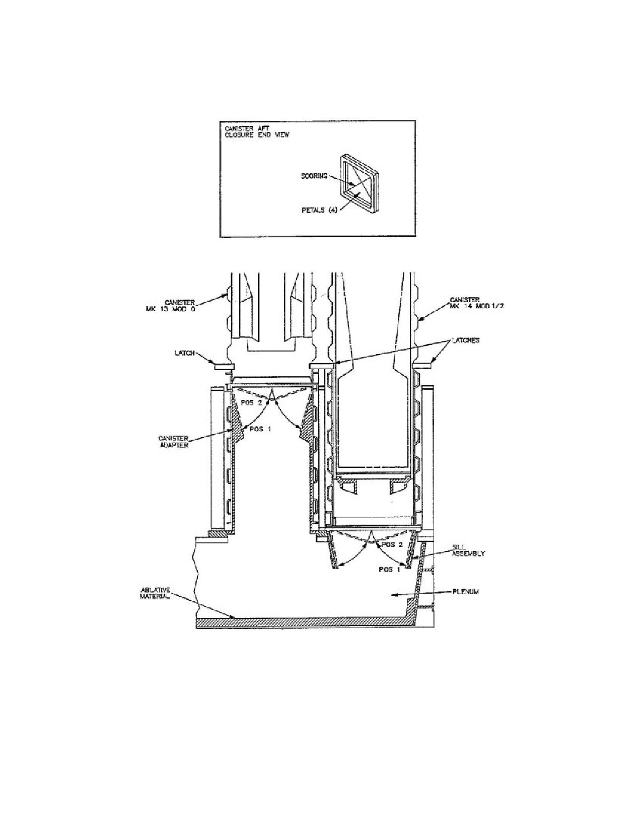
SW820-AP-MMI-010
REVISION 15
27 MARCH 2009
CHAPTER 3
Figure 3-3. VLS Exhaust Gas Control
202
SW820-AP-MMI-010
REVISION 15
27 MARCH 2009
CHAPTER 3
Table 3-1. Land-Attack TCM CMGS Alignment Modes
MODE
COMMENT
0, Warmup
Mode 0 performs the first set of BITs and sequences the CMGS
inertial platform into gyro control. Operations include warmup,
loading of operational flight program, initialization, BIT, gyro
caging and gyro spinup. BIT results are contained in the MISSILE
STATUS word. If all BITs are passed and gyros have spun up, the
mode number advances to Mode 1.
1, Standby
Mode 1 tests availability to present position and checks to see
if inertial platform is under gyro control. Program will advance
to Mode 2 when present position is available and platform is
determined to be under gyro control.
2, Course Level
During Mode 2, the inertial platform is torqued to level by
computer program torquing commands. Mode is complete when
the computed tilt angle and mode time tests are passed.
3, Spare
Not used.
4, Align Axis#1
Mode 4 performs the first fine alignment phase and is completed
when a series of mode time, computed tilt angle, gyro bias
change and azimuth angle change tests are satisfied. If sufficient
maneuvering occurs in this mode to estimate the platform azimuth
angle, Modes 5 and 6 are bypassed and Mode 7 will be entered
at alignment completion.
5, Slue
During Mode 5, the platform is slued 90° from its previous
orientation by torquing the vertical gyro.
6, Align Axis #2
Mode 6 performs the second fine alignment phase and duplicates
the Mode 4 alignment. Upon passing of mode completion tests, the
alignment process advances to Mode 7.
7, Alignment Complete
Mode 7 is used only to indicate that alignment complete tests have
been passed. The computer program continues to perform the Mode
6 alignment until the CMGS is commanded to terminate alignment.
When this occurs, the computer program advances to Mode 8.
8, Navigate
Mode 8 signals that the CMGS has terminated alignment, and it has
become an independent navigator.
203
SW820-AP-MMI-010
REVISION 15
27 MARCH 2009
CHAPTER 4
CHAPTER 4
OPERATIONS
SECTION I.
4.1 SCOPE.
This chapter discusses TWS operations aboard the various types of launch platforms. These
discussions include: brief descriptions of the launch platforms and on board equipment used to
load, store and launch weapons; typical weapon onload scenarios; and typical launch operations.
Section II discusses TTL launch platforms, procedures and operations. Section III discusses
CLS launch platforms, procedures and operations. Section IV discusses VLS launch platforms,
procedures and operations.
204
SW820-AP-MMI-010
REVISION 15
27 MARCH 2009
CHAPTER 4
SECTION II. TORPEDO TUBE LAUNCH
4.2 LAUNCH PLATFORMS.
The TTL TWS is employed aboard SSN 688, SSN 774, and SSN 21 Class submarines. TCM
launch operations are performed utilizing equipment located in the Attack Center, Combat
Systems Electronic Space (CSES) and Torpedo Room. General locations of the complexes are
shown in Figure 4-1 "General Locations of SSN Complexes"⇒. The following paragraphs
describe the major TWS-related TTL systems aboard the submarine. A simplified interface
block diagram of submarine TWS-related equipment is shown in Figure 4-2 "SSN/TWS-related
Equipment TTL Interfaces"⇒.
4.2.1
Submarine Combat System. Submarine Combat Systems (SCS) include the Combat
Control System (CCS) and the AN/BSY-1 Combat Control/Acoustic Set (CC/A). SSN 688 Class
submarines may employ either the CCS or CC/A. Each SCS, supported by the ownship navigation
system, CSES, Over-the-Horizon (OTH) targeting and the appropriate software programs,
provides the necessary power, discretes and data to power up weapons, transmit orders, process
and display data, initialize and align the missile guidance set, and initiate weapons launch. Also
included are control and monitoring circuits as well as various firing interlocks.
4.2.2
Combat Systems Electronic Space (CSES). The CSES equipment is shared by both the
SCS and the navigation system. Computer software programs, which include the operational
flight program, preplanned land-attack mission/targeting data generated at a shore-based Theater
Mission Planning System (TMPS) installation and provided to the submarine prior to deployment,
platform alignment data and sequential control commands, are stored on disks in the CSES. The
data are loaded into computer memory and sent to the missile on command. Missile responses
and status are evaluated by the CSES to provide data for displays on TCM status, Built-In-Test
(BIT), checksums and launch countdown.
4.2.3
Navigation Equipment. TOMAHAWK capable submarines are equipped with either the
Electrically Suspended Gyro Navigator (ESGN) AN/WSN-3A(V)2 or the Dual Miniature Inertial
Navigation System (DMINS) AN/WSN-1(V)2. Each system consists of two Inertial Measuring
Units (IMUs) and one dual-channel Navigation Control Console (NCC). Velocity and attitude
data are generated in raw form by the IMUs and transmitted to the CSES via the NCC. The raw
data are processed by the CSES computers to obtain velocity, attitude and position data and then
transmitted to various ship user subsystems.
4.2.4
Weapon Launch and Pressurization/Vent Equipment. The SSN 688 Class submarine
weapon launch equipment consists of a weapon launch console (WLC) flanked by two banks
of canted torpedo tubes; two tubes port and two tubes starboard. Also included are four PVC
manifolds (one for each torpedo tube) to control the air which pressurizes the TCM prior to
launch. Pressurization and torpedo tube pre-launch operations are controlled from the WLC.
Figure 4-3 "SSN TTL Pressurization/Vent Control System"⇒ depicts the PVC system.
4.2.5
Weapon Shipping/Unshipping Equipment. Both the SSN 688 and SSN 774 Class
submarines use a shipping line to ship and unship weapons. On SSN 688 Class submarines, the
major components are a portable topside deck skid, intermediate shipping rails and a shipping
205
SW820-AP-MMI-010
REVISION 15
27 MARCH 2009
CHAPTER 4
tray located in the torpedo room. The weapons, restrained by a shipping harness, are lowered
or raised along the shipping line, aft end down, using a chain drive. Figure 4-5 "TTL Weapon
Shipping, Handling and Stowage Equipment (SSN 688 Class)"⇒ depicts SSN 688 Class
submarine shipping, handling and stowage equipment. On SSN 774 Class submarines, the major
components are a portable topside deck skid, intermediate and shipping trunk mounted shipping
rollers, and a shipping cradle located in the torpedo room. The weapons, restrained by a shipping
nose piece and shipping cables, are lowered or raised along the shipping line, forward-end down,
using a pier-side crane connected to the shipping cables.
4.2.6
Weapon Handling and Stowage Equipment. Two-level stowage racks are provided aft
of the torpedo tubes for stowage of weapons. On the SSN 688 Class, the weapons are supported
by dollies on athwartship tracks and are restrained by lashing straps. On the SSN 774 Class, the
weapons are supported in cradles which in turn are supported at each end by an end truss track
and restrained by lashing bands. Transfer of weapons to the torpedo tube, or to any other stowage
position or working space, is accomplished via athwartship transfer mechanisms, vertical hoist(s),
pivot mechanisms/trays and loading rammers.
4.3 WEAPON ONLOAD.
The supporting submarine tender or shore base removes the weapon from its shipping container
and places the weapon on the topside skid (SSN 688 Class). Subsequent actions to lower the
weapon to the torpedo room are depicted in Figure 4-5 "TTL Weapon Shipping, Handling and
Stowage Equipment (SSN 688 Class)"⇒ for SSN 688 Class submarines. Weapon onload is
performed in accordance with applicable volumes and parts of NAVSEA OD 44979.
4.4 OPERATIONAL CONSTRAINTS/RESTRICTIONS.
Tactical employment of a TCM may impose constraints on the operating parameters of the
submarine and restrictions on the submarine’s tactical flexibility. The following paragraphs
identify the different constraints and methods of alerting the ship’s commanding officer to an
operational constraint or restriction.
4.4.1
Launch Constraints. The launch constraints imposed on the operational parameters of
the submarine during employment of tactical and exercise variants are described in the applicable
tactical employment manuals.
4.4.2
Weapon Mix. Weapon mix will depend on the particular conditions that exist at the time
the decision is made to load torpedo tubes. The SCS is capable of processing a combination of
TOMAHAWK variants, Mk 48 Torpedoes and other defensive systems. Prime consideration
for specific weapon mix is the time required to prepare and launch a TCM, to include the time
required to recycle the torpedo tube and, when authorized, to eject the capsule.
4.4.3
Alert Messages and Interlocks. Various alert messages and firing interlocks are used to
warn operators or inhibit launch when conditions exist that could impact missile performance,
endanger the submarine or result in the launch of a dud missile. Firing interlocks may be either
software or hardware interlocks. Prior to permitting activation of the FIRE switch, the submarine
fire control system must receive an indication that the following interlocks are closed:
a. WPN IDENT - Indicates that the designated weapon is loaded in torpedo tube
206
SW820-AP-MMI-010
REVISION 15
27 MARCH 2009
CHAPTER 4
b. INPUTS MATCHED - Indicates that all mission data have been transferred to the
missile and the CMGS has responded with appropriate MISSILE STATUS and GOOD
DATA words
c. WITHIN LIMITS - Indicates that speed and depth of the submarine are within limits
d. TUBE READY - Indicates that the torpedo tube outer door is open
e. BOOSTER ARMED - Indicates that the rocket motor igniter is armed
f. WARHEAD PREARMED - Indicates that the UGM-109A-1 warhead is in prearmed
condition.
g. PRESSURE IN BAND - Indicates that missile pressure is between 3.8 - 7.2 psid.
Upon activation of the FIRE switch and indication of MISSILE ENABLED (i.e., batteries
activated, BIT passed, MISSILE STATUS word good), the fire control system performs a firing
interlock check and closes final interlocks prior to permitting the impulse fire relay to energize
and eject the TCM from the torpedo tube.
4.5 LAND-ATTACK TCM OPERATIONAL SEQUENCE.
This paragraph describes typical actions and responses required to launch a land-attack TCM.
Primary coverage is given to a normal launch. Abnormal launch conditions and abort procedures
are discussed by highlighting only those events that differ from a normal launch. Typical launch
operations are shown in Figure 4-6 "UGM-109-1 Land-Attack TCM Operational Sequence (7
Sheets)"⇒. The figure illustrates the orders given by the ship’s commanding officer, typical
actions taken by equipment operators and typical equipment operations, status displays and
machine decisions. The operational sequence is described in the following paragraphs. Operating
procedures and checklists, as well as actions to be taken under abnormal conditions, are contained
in appropriate volumes and parts of NAVSEA OD 44979.
4.5.1
Weapon Preparation and Tube Loading. Preparation starts with the authorization to
launch a land-attack TCM. A torpedo tube is made ready for loading. For a UGM-109A, the 4FZ
Security Alarm System is disconnected and the capsule security band unlocked and removed.
The weapon serial number is reverified. The missile is then depressurized and moved to the
loadline where the slot covers are removed.
4.5.1.1
The loading pole is attached between the rammer and capsule loading button. Upon order
to load tube, the loadline rollers are raised and ramming is commenced. The capsule nose cover
and lashing straps are removed as they clear the forward loadline rollers. Ramming is continued
until the capsule forward guide stud contacts the tube stop bolt. The stop bolt is then rotated to the
LOCK position. On a UGM-109A/C/D-1, the capsule latch pins are pulled to allow the capsule
latches to extend and engage the slots in the aft land of the torpedo tube. On a UGM-109E-1, the
retention fixture is installed in the torpedo tube and secured to the capsule. The loading pole is
removed. Two shipping nuts are then removed from the missile holdback assemblies.
4.5.1.2
After verifying STOP BOLT LOCKED indication, covers are removed and the electrical
umbilical is connected between the breech door Y-connector and the missile and secured to the
inside of breech door. The pneumatic umbilical is connected between the breech door penetrator
207
SW820-AP-MMI-010
REVISION 15
27 MARCH 2009
CHAPTER 4
and the capsule and secured to the eyebolt on the inside of the breech door. The breech door is
shut and locked.
4.5.2
Weapon Power-Up and Make Ready. Weapon power-up and make ready is initiated
by the weapon control console (WCC) operator in the attack center. The WCC operator
activates switches to select Land-Attack TOMAHAWK mode, Land-Attack TOMAHAWK
Preset Submode and the designated torpedo tube to be used for launch. These selections permit
the WCC operator to monitor the selected tube and any alerts concerning launch. The weapon
launch control (WLC) operator in the torpedo room positions the designated tube weapon loaded
switch to the assigned missile variant. This action initiates alignment of torpedo room equipment
to the selected weapon and allows verification in the attack center, through displays on equipment
indicators, that the appropriate weapon is loaded in the tube. If such verification can not be
obtained, the launch is recycled or aborted.
4.5.2.1
When ordered, FIRING ORDER and MAKE READY ORDERED are input by the
attack control console (ACC) operator which permit other operator actions and equipment
responses to commence in preparation for launch. The mission disk pack is removed from secure
storage and mounted on the random access storage set (RASS). The disk pack serial number is
entered and the RASS is initialized.
4.5.2.2
The WLC operator positions the designated tube weapon supply switch to POWER ON.
WEAPON READY indicators appear on the WCC, ACC and WLC to reflect that the weapon
is ready to receive commands. A tube status check is again performed to verify readiness. If
WEAPON READY indicators are not obtained, the launch is recycled or aborted.
4.5.2.3
Positioning the weapon supply switch to POWER ON applies DC MONITOR/RESET
POWER to the PVC system and a PRESSURIZE indicator appears on the WLC. Upon receipt of
this indicator, the ship 700-psi air isolation valve of the designated tube pressure/vent manifold is
opened to supply air to the missile. When missile pressure stabilizes between 3.8 and 7.2 psid,
a PRESSURE IN BAND indicator appears on the WLC and the PRESSURIZE indicator goes
out. PRESSURE IN BAND, PRESSURIZE and VENT indicators may cycle on and off during
the preparation for launch due to changes in missile pressure.
4.5.3
Mission Assignment. With RASS initialized, the CMGS is ready to accept mission
data when BALLISTICS SET and CMGS PROGRAMMED are indicated to the WCC operator
(CMGS flight program has been transferred to the missile and the missile has responded with
a valid Missile Status Word.). The WCC operator changes the submode until Land-Attack
TOMAHAWK Evaluation is indicated on the WCC. THEATER, MPS, MISSION and VERIFY
codes are received from the appropriate authority and entered on the WCC. Mission data are
then indicated on the WCC. Mission data are also transferred to the central computer resident
memory. The WCC operator enters the target number and the pre-established waypoints to that
target are displayed on the WCC. The WCC operator reviews the mission data and approximate
flight path to the target and makes route alterations by introducing or deleting waypoints. The
WCC operator then assigns the mission to a designated torpedo tube and a verification that the
mission is assigned to the correct tube is performed. Once a mission has been assigned, no
further modifications can be made without resetting the mission and then reentering the mission
208
SW820-AP-MMI-010
REVISION 15
27 MARCH 2009
CHAPTER 4
number and verification code. After assigning the mission, the WCC operator normally selects the
Land-Attack TOMAHAWK Preset submode for the remainder of the launch in order to monitor
torpedo tube and missile status and any alerts concerning launch.
4.5.3.1
CMGS alignment begins automatically upon completion of a successful upload of the
Operational Flight Program (OFP). The mission data are loaded into the CMGS and a course level
is performed, followed by the alignment of axis#1. The inertial platform is then slued 90° and
alignment of axis #2 is performed. The two-position alignment technique eliminates the need to
perform submarine maneuvers at latitudes below 75°. If the submarine is maneuvering and the
CMGS can estimate platform azimuth angle during alignment of axis#1, the slue and alignment
of axis #2 will be bypassed. Launches at latitudes above 75°, however, will require submarine
maneuvers to meet the alignment timeline. Upon completion of alignment, the CMGS will
provide an ALIGNMENT COMPLETE message to the WCC operator.
4.5.3.2
If CMGS computer BIT is not passed, or valid communications can not be established
or becomes lost with the CMGS computer, an alert message is provided to the WCC operator.
To establish or restore communications, a controlled shutdown of the CMGS is performed and
missile electrical power recycled. The normal start-up sequence is then repeated and program load
reattempted. When program load is accomplished, the reprogram command is sent to the CMGS.
4.5.4
Tube Ready. The final steps to launch the missile are making the torpedo tube ready and
arming the weapon. Upon receipt of indications that alignment and mission transfer are complete
and that inputs match, the ACC operator gives the order to flood the designated torpedo tube.
Responding to the order, the WLC operator floods the tube, and when so ordered, equalizes
tube pressure with ambient sea pressure. Indicators advise operators that the tube is flooded
and equalized. When ordered, the ACC operator orders OPEN DOOR for the designated tube.
Responding to the order, the WLC operator opens the muzzle door. Indicators advise ACC and
WLC operators that the muzzle door is open. When ordered, the WLC operator turns the launch
mode switch to EJECT. The ACC operator selects the firing tube and a NEXT indicator appears.
4.5.5
Rocket Motor Arming. When ordered, the booster armed and warhead arm supply
key-lock (UGM- 109A only) switches are activated by the ACC operator for the designated tube.
BOOSTER ARMED indicators on the ACC and WLC advise operators of successful arming
of the rocket motor. If indicators do not reflect that the rocket motor is armed, the launch is
recycled or aborted.
4.5.6
Warhead Prearming (UGM-109A only). When ordered, the warhead arm switch on the
ACC is activated for the designated tube. After approximately 24 to 40 seconds, WARHEAD
ARMED indicators on the ACC and WLC will advise operators that the warhead has been
successfully prearmed.
4.5.7
Weapon Firing. With INTERLOCKS CLOSED indicated and firing status ready, the
order is given to the ACC operator to position the STANDBY/FIRE switch to STANDBY.
Upon order, the switch is then positioned to FIRE and held until the FIRE indicator is present.
Subsequent actions occur automatically. The missile batteries activate and missile essential
busses are isolated. The CMGS performs a status check using battery power and, if successful,
sends a MISSILE ENABLED signal. With the closing of final interlocks, the impulse fire
209
SW820-AP-MMI-010
REVISION 15
27 MARCH 2009
CHAPTER 4
relay energizes, the stop bolt rolls, the electrical umbilical deadfaces, and the tube fires. Upon
firing, TUBE FIRED indicators on the ACC and WLC advise operators that the tube has been
successfully fired. If indicators reflect that the tube was not successfully fired, the launch is
aborted in accordance with NAVSEA OD 44979.
4.6 POST-LAUNCH OPERATIONS.
The post-launch operational sequence begins after the missile has been launched from the torpedo
tube. Operations consist of those evolutions to either eject the capsule or return the capsule to the
stowage racks. The operations also include resetting the tube if required, and securing the torpedo
tube. A typical post-launch sequence is briefly described in the following paragraphs. Post-launch
operations are preformed in accordance with NAVSEA OD 44979.
4.6.1
Tube Reset. If the WLC indicator continues to show TUBE FIRED at the completion of
missile launch, the WLC operator takes action to reset the tube and close the outer door.
4.6.2
Capsule Ejection. (UGM-109A/C/D-1) When ordered to eject capsule, the WLC operator
positions the missile interrupter switch to MANUAL and the tube stop to LOCK. The WLC
operator then activates the switch to route ship 700-psi air to the capsule. Upon application of air
pressure, the capsule sleeve moves forward, unlocking the capsule latches. Continued movement
of the capsule sleeve retracts the capsule latches and closes the flow slots. With the closing of the
flow slots, the weapon supply switch on the WLC is turned to OFF.
(UGM-109E-1) When ordered to eject capsule, the WLC operator shall unload the capsule from
the torpedo tube in accordance with NAVSEA OD 44979. The capsule nose cover shall be
re-installed. The AUR will then be loaded back into the torpedo tube.
4.6.2.1
When ordered, the ACC operator orders OPEN DOOR. Responding to the order, the
WLC operator opens the muzzle door. WLC and ACC indicators advise the operators that the
tube is ready to eject the capsule. On order, the tube is fired and the capsule ejected. If indicators
show that the tube did not fire, operators refer to NAVSEA OD 44979 for further guidance.
4.6.2.2
Upon receipt of indicators that the tube successfully fired, the WLC operator closes the
muzzle door, turns the weapon loaded switch to OFF, secures the ship 700-psi air isolation valve
to the pressure/vent manifold, and drains the tube. After the tube is drained, the breech door is
opened. The umbilicals and inside of the breech door are rinsed with fresh water to remove salt
water residue, and then dried. The umbilicals are then disconnected and removed, and the tube is
secured using procedures contained in NAVSEA OD 44979.
4.6.3
Capsule Return to Stowage. Upon order to stow capsule, the WLC operator turns the
weapon supply and weapon loaded switches to OFF, secures the ship 700-psi air isolation valve to
the pressure/vent manifold and drains the tube. The breech door is then opened and the umbilicals,
the inside of the breech door and the aft face of the capsule are rinsed with fresh water to remove
salt water residue, and dried. The umbilicals are then disconnected and removed. The capsule
latches are manually retracted by pressing and holding their spring-loaded plungers; then lifting
the latches and securing them with the pins provided. The capsule is removed from the tube using
210
SW820-AP-MMI-010
REVISION 15
27 MARCH 2009
CHAPTER 4
procedures contained in NAVSEA OD 44979 rinsed with fresh water, dried, covers installed and
the capsule is then moved and secured to a stowage position.
4.7 LAND-ATTACK TCM CASUALTY MODE.
There is no casualty mode for land-attack TCM variants.
211
SW820-AP-MMI-010
REVISION 15
27 MARCH 2009
CHAPTER 4
SECTION III. CAPSULE LAUNCHING SYSTEM
4.8 LAUNCH PLATFORM.
The TWS provides selected SSN-688 Class, SSN-774 Class and SSGN-726 Class submarines
with the capability to carry, target, and launch TCMs against enemy land targets. TCM launch
operations are performed aboard the submarine utilizing equipment located in the Attack Center,
Combat Systems Electronic Space (CSES) and Vertical Launch Center. General locations of
the complexes are shown in Figure 4-8 "General Locations of SSN 688 Class Submarine
Complexes"⇒. The following paragraphs describe the major TWS-related CLS systems aboard
the submarine. A simplified interface block diagram of TWS-related equipment aboard the
submarine is shown in figure 4-9 "SSN 688 Class Submarine TWS-related Equipment Interfaces
(2 Sheets)"⇒.
4.8.1
Submarine Combat System (SCS). The SCS include the Combat Control System
(CCS) and the AN/BSY-1 Combat Control/Acoustic Set (CC/A). SSN 688 Class submarines
may employ either the CCS or CC/A. Each SCS, supported by the ownship navigation system,
CSES, Over-the-Horizon targeting (OTH-T) and the appropriate software programs, provides the
necessary power, discretes and data to power up weapons, transmit orders, process and display
data, initialize and align the missile guidance set, and initiate weapons launch. Also included are
control and monitoring circuits as well as various firing interlocks.
4.8.2
Combat Systems Electronic Space (CSES). The CSES equipment is shared by both the
SCS and the navigation system. Computer software programs, which include the operational
flight program, preplanned land-attack mission/targeting data generated at a shore-based Theater
Mission Planning System (TMPS) installation and provided to the submarine prior to deployment,
platform alignment data and sequential control commands, are stored on disks in the CSES. The
data are loaded into computer memory and sent to the missile on command. Missile responses
and status are evaluated by the CSES to provide data for displays on TCM status, Built-In-Test
(BIT), checksums and launch countdown.
4.8.3
Navigation System. SSN/VLS capable submarines are equipped with the Electrically
Suspended Gyro Navigator (ESGN) AN/WSN-3A(V)2. The system consists of two Inertial
Measuring Units (IMUs) and one dual-channel Navigation Control Console (NCC). Velocity and
attitude data are generated in raw form by the IMUs and transmitted to the CSES via the NCC.
The raw data are processed by the CSES computers to obtain velocity, attitude and position data
and then transmitted to the various ship user subsystems.
4.8.4
Weapon Launch System. The weapon launch system consists of the missile tube
assembly and the various ship systems which operate the missile tube assembly during stowage
and launch operations. The following paragraphs describe the components of the weapon launch
system.
4.8.4.1
Missile Tube Assembly. The missile tube assembly (Figure 4-10 "SSN 688 Class
Submarine Missile Tube Assembly"⇒) houses and physically protects the weapon in the
missile tube. The assembly consists of the missile tube, hatch and linkage gear, and interfaces
to operate the assembly. Ship system interfaces include connections for the flood and drain and
212
SW820-AP-MMI-010
REVISION 15
27 MARCH 2009
CHAPTER 4
pressurization/vent systems. AUR interfaces provide shock mitigation and alignment of the
AUR as well as a means to pressurize the AUR in the missile tube. Missile tubes are topped by
hatches that are individually operated by outboard hydraulic rotary actuators and are locked by an
over-center toggle linkage mechanism with locking further enhanced by a device to assure that
hatches do not inadvertently open when adjacent tubes are subjected to launch pressure.
4.8.4.2
Hydraulic System. The hydraulic system (Figure 4-11 "SSN 688 Class Submarine
Hydraulic System"⇒) provides power to actuate flood and drain system valves and missile
tube hatches.
4.8.4.3
Pressurization/Vent System. The pressurization/vent system (Figure 4-12 "SSN 688
Class Submarine Pressurization/Vent System"⇒) replenishes the AUR internal atmosphere
during stowage and pressurizes or vents the AUR to maintain internal pressure within a specified
range of positive pressure over the underhatch volume pressure prior to launch using 700 psig
ship service air.
4.8.4.4
Flood and Drain System. The flood and drain system (Figure 4-13 "SSN 688 Class
Submarine Flood and Drain System"⇒) floods and equalizes the missile tube underhatch volume
to sea pressure so that the hatch can be opened, drains the underhatch volume to remove water
and allows this volume to be maintained at submarine internal ambient pressure.
4.8.4.5
Missile Tube Control System. The missile tube control system (Figure 4-14 "SSN 688
Class Submarine Missile Tube Control System"⇒) contains the controls, indicators, and interlock
circuitry necessary to ready the missile tubes for launch and to monitor missile tube operation.
The system also provides all of the interfaces between the ship systems and the SCS.
4.9 ONLOAD AND OFFLOAD.
The following paragraphs provide general information regarding preparation for, and onload
and offload of weapons, as well as offload of a spent CLS. Various volumes of NAVSEA
OD 44979 contain specific procedures to be used by SSN personnel. Technical manual
SW820-AD-WHS-010/UGM-109-2 contains specific procedures for submarine tender and shore
based personnel supporting SSNs. For SSGN Class procedures refer to NAVSEA OD 64501 and
SW820-AD-WHS-040/UGM-109-2.
4.9.1
Onload. Submarine onload begins when the submarine arrives at a designated shore
base activity or supporting submarine tender to receive a complement of weapons. Wind and
sea motion, which affect the submarine’s position and movement, are factors in determining
the feasibility of loading operations. To prevent damage to the missile, ship, or equipment,
it is recommended that weapons not be onloaded or offloaded if roll exceeds 3 degrees or pitch
exceeds 1/2 degree, and winds exceed 30 knots. The submarine tender/shore base loading
supervisor and the submarine’s commanding officer will determine if conditions are satisfactory
prior to commencing onload. Prior to onload, the security system is neutralized for each missile
tube to be loaded; flood and drain system and pressure/vent system operability are verified at the
VLC; and SCS operability is verified through operator conducted system diagnostics. During
loading, responsibility for all operations is shared between the submarine’s commanding officer
and the submarine tender/shore base loading supervisor. All actions involving ship system
213
SW820-AP-MMI-010
REVISION 15
27 MARCH 2009
CHAPTER 4
preparation are the responsibility of the submarine’s commanding officer. His permission is
required prior to commencing loading operations. His designated representative is responsible
for weapon handling operations and ensures that a weapon transfer inspection is conducted.
Upon completion of submarine preparation, responsibility for loading transfers to the submarine
tender/shore base loading supervisor. The submarine crew conducts the final hookup and
closeout of the missile tube upon disconnect and removal of the loading equipment from the
submarine. The following paragraphs provide a general overview of procedures used during
loading operations. For purposes of illustration, loading of a generic weapon into one missile
tube is discussed. There are some minor differences in loading procedures among AURs, AUR
Simulator Volumetric Shapes and ballast cans which are not discussed. For multiple loadings,
the procedures are the same except that multiple actions may be occurring simultaneously to
prepare missile tubes and weapons. Additionally, loading equipment is moved from missile
tube to missile tube until the full complement of weapons is aboard the submarine. Similarly,
post-loadout is accomplished on a tube by tube basis until full closeout is accomplished. Onload
terminates when the submarine has received its scheduled complement, final hookup has been
accomplished, all loading equipment has been removed, missile tube hatches are closed and
secured, and ship system equipment has been activated.
4.9.1.1
Prepare Missile Tube and Ship Systems. After supporting submarine tender/shore
base personnel have erected the loading platform (Figure 4-15 "Loading Platform Installed"⇒).
submarine personnel prepare the missile tube and ship systems for onload. The missile tube hatch
is opened and gagged (Figure 4-16 "SSN 688 Class Submarine Missile Tube Equipment"⇒). and
the missile tube is visually inspected to ensure it is free of potential contaminants. Contaminants,
if present, will damage the lip seal on an AUR or o-ring on an AUR Volumetric Shape/Simulator
during loading. The muzzle face protective cover and the missile tube muzzle hatch and
magnet protective cover are installed (Figure 4-16 "SSN 688 Class Submarine Missile Tube
Equipment"⇒). For the AUR Volumetric Shape/Simulator onload, the mylar O-ring protective
sleeve assembly is also installed. Special procedures like direct tube to tube transfer of AURs
on the same submarine or between different submarines may utilize lip seal protective covers
(fabricated from split garden hose or equivalent) or a lip seal protective sleeve (fabricated from
various sheet materials). The counterbore cover is installed to prevent personnel, tools, water
and debris from entering the empty missile tube. The Environmental Monitoring Sensor (EMS)
pressure and temperature ambients are checked, and a leak test performed. SCS circuits are
checked using the All-Up-Round Electronic Simulator (AURES). The accuracy of the differential
pressure transducer is verified and the pressurize/vent (P/V) plug is removed and stowed. The
counterbore cover is removed.
4.9.1.2
Install Loading Equipment. After the missile tube and ship systems have been
prepared for loading, submarine tender/shore base personnel install the loading equipment aboard
the submarine. This includes the Installation Guide Assembly Mk 116, Hydraulic Power Unit
(HPU) Mk 8, Missile Tube Extension Loader (MTEL) Mk 23 and the MTEL Safety Cover. The
installation guide is installed on the missile tube inner shoulder to assist in centering the MTEL
over the missile tube. The MTEL is lowered over the missile tube, maneuvered to align its
guide holes with the missile tube pins, and bolted to the muzzle face. The installation guide is
then removed. The MTEL safety cover is installed over the MTEL mouth to prevent objects from
214
SW820-AP-MMI-010
REVISION 15
27 MARCH 2009
CHAPTER 4
falling into the open missile tube. The HPU is positioned on the loading platform and connected
to the electrical source aboard the submarine. Hoses are connected between the HPU and the
MTEL. A check is made to insure the centering guides and the insertion pin stop-plates are in
the correct position on the MTEL
4.9.1.3
Prepare Weapon. As the missile tube and ship systems are being prepared for loading
and loading equipment is being installed, submarine tender/shore base personnel prepare the
weapon for loading. After opening the Shipping and Storage Skid Mk 30, two trunnions or
trunnion bearing assemblies are installed in the weapon to allow vertical uprighting with either
the Tilt Fixture, Mk 23 Mod 0 with Kit B, or a Shipping and Storage Skid Mk 30 that has
been rigged for uprighting. The weapon is removed from the skid and placed in the uprighting
equipment being used where, if not previously performed, a pressure check and inspection, to
include rocket motor safe/armed and weapon configuration tests, are performed. Interface support
and elastomer loading guard pads as well as the upper flange grooves are greased to facilitate
loading the weapon into the missile tube. The forward section of the weapon is depressurized
and the Closure Protective Cover (CPC) is replaced with the Capsule Loading Cover (CLC). The
annular space vent plug is removed and stowed. Two lip seals are then greased and carefully
installed into the upper flange grooves. The lifting adapter is then attached to upright the weapon
to the vertical position.
4.9.1.4
Load Weapon in Missile Tube. The weapon is uprighted about the trunnions or
trunnion bearing assemblies and lifted off the Mk 23 fixture (Figure 4-34 "Tilt Fixture Mk 23
Mod 0 with Kit B"⇒) or uprighting skid (Figure 4-17 "CLS Weapon Onload"⇒). The trunnions
or trunnion bearing assemblies are removed and the weapon is lifted over the MTEL and aligned
for insertion into the missile tube. The MTEL safety cover is removed. The weapon is lowered
into the MTEL until the bellyband and the moisture and dust plug can be sequentially removed.
The MTEL centering guides are released to allow the flange to pass, permitting the weapon to be
lowered until the lifting adapter is above the bellmouth. The lifting adapter arm is then pinned
in the vertical position and the weapon is further lowered until the lifting adapter insertion pins
rest on the MTEL stop plates (Figure 4-18 "CLS Weapon Seating in Missile Tube"⇒). Seating
the weapon in the missile tube is accomplished hydraulically using the HPU. The lifting adapter
arm is disconnected from the crane and the MTEL hydraulic cylinders are connected to the
lifting adapter insertion pins. The hydraulic cylinders are extended using the HPU until the
weapon seats in the missile tube.
4.9.1.5
Remove Loading Equipment. After the AUR has been fully seated in the missile tube,
the MTEL hydraulic cylinders are disconnected from the lifting adapter insertion pins. The
insertion pins are inserted into the lifting adapter and the MTEL hydraulic cylinders are then fully
retracted. The HPU is disconnected from the MTEL and the MTEL unbolted from the muzzle
face and removed from the deck. The lifting adapter is unbolted and removed from the weapon
which signifies completion of the loading sequence and final hookup and testing becomes the
responsibility of submarine personnel.
4.9.1.6
Post-Loadout. Post-loadout involves connecting the weapon to the ship systems
through missile tube interfaces (Figure 4-19 "Secure CLS Weapon in Missile Tube"⇒). The
umbilical cable connector is connected to the missile tube umbilical connector. Eight retention
215
SW820-AP-MMI-010
REVISION 15
27 MARCH 2009
CHAPTER 4
segments are installed to restrain the CLS in the missile tube at launch. Umbilical cable brackets
are connected to the retention segments to restrain the umbilical. The SCS, missile tube, and
weapon are then tested to ensure operability. The annular space vent is plugged and the P/V
sensing line connected to the pressure transducer in the missile tube. A leak test at the missile
tube hatch opening is conducted and the underhatch area cleaned. The CLC is removed and the
capsule closure is inspected to ensure no damage occurred during loading. The missile tube hatch
and fairing are then closed and the loading platform removed.
4.9.1.7
SSGN Onload Overview. The following paragraphs provide a brief description of the
unique aspects of onloading the Tomahawk onboard a SSGN-726 Class submarine.
4.9.1.8
AUR Onload Sequence. An onload sequence begins with staging and preparing the
work platform (Figure 4-4 "MTEL Work Platforms"⇒) onto the MTEL, attaching the MTEL
adapter (Figure 4-7 "MTEL With MTEL Adapter Installed"⇒) onto the MTEL, and attaching
the lifting adapter extension (Figure 4-21 "Lifting Adapter and Extension"⇒) onto the lifting
adapter. The MTEL work platform, the MTEL adapter and the lifting adapter extension are
support equipment unique to SSGN.
4.9.1.9
Organizational-Level Preparations. The submarine crew opens the missile tube
hatch providing access to the Multiple All-Up-Round Canister (MAC) (Figure 4-33 "Multiple
All-Up-Round Canister (Fully Loaded)"⇒) and its individual AUR cells, and tags out the
hydraulic system. The appropriate AUR cells are inspected for dirt, debris or foreign material that
will damage lip seals during loading, and the area is cleaned as required.
4.9.1.10
Installing Loading Equipment. The HPU is transferred and secured to the SSGN
work area. There are two different MTEL Adapters and each must be used in the appropriate
AUR cells. The 7124601-003 Adapter is used with MAC cells A, C, E, and G. The 7124601-004
Adapter is used with MAC cells B, D and F (Figure 4-35 "Multiple All-Up-Round Canister
MTEL Orientation"⇒). The prepared MTEL/MTEL Adapter is lowered onto the AUR cell and
oriented with the large and small alignment pins temporarily placed in the MAC top plate. The
MTEL/MTEL Adapter is secured to the MAC with four bolts. The hydraulic hoses from the HPU
are connected to the manifold on the MTEL.
4.9.1.11
Uprighting and Inserting. Procedures to upright the AUR are similar to the SSN Class
with the exception of installing the lifting adapter extension. Inserting the AUR is essentially
the same as for the SSN Class as well, with the MTEL adapter providing an interface between
the existing MTEL design and the MAC top plate. The additional height of the MTEL adapter
requires the lifting adapter be attached to the AUR with an extension of equal height.
The MTEL adapter is outfitted with a guide ring. The guide ring can be rotated to the open or shut
position to engage or disengage the guide shoes. The guide shoes perform the same function as
the MTEL centering guides, which is to assist in keeping the AUR in the center of the cell during
loading and offloading operations.
4.9.1.12
Removing Loading Equipment. The MTEL/Adapter is unbolted from the MAC top
plate and removed. The lifting adapter/extension is unbolted from the capsule upper flange and
removed. The HPU is disconnected from the electrical power source and removed.
216
SW820-AP-MMI-010
REVISION 15
27 MARCH 2009
CHAPTER 4
4.9.1.13
Organizational-Level Closeout Operations. Topside personnel connect the
pressure/vent sensing line and install the eight retention segments to secure the AUR in the AUR
cell. Topside personnel mate the AUR upper umbilical cable connector to the MAC umbilical
cable stowage receptacle. Inside the MAC, the crew connects the AUR ground strap, moves the
P1130 connector to the stowage position of the aft cover, and mates the MAC umbilical cable to
the J1130 connector (Figure 4-36 "AUR Aft Cover Viewed in MAC"⇒). Each AUR requires
one MAC umbilical to be connected to the J1130 connector. A bubble test is performed on the
installed AUR to check for leaks at the MAC top plate.
4.9.2
Offload. Submarine offload begins when the submarine arrives at a designated shore
base activity or supporting submarine tender to discharge a complement of weapons or spent
CLSs. Wind and sea motion, which affect the submarine’s position and movement, are factors
in determining the feasibility of offload operations. To prevent damage to the missile, ship,
or equipment, it is recommended that weapons not be offloaded if roll exceeds 3 degrees or
pitch exceeds 1/2 degree, and winds exceed 30 knots. The submarine tender/shore base loading
supervisor and the submarine’s commanding officer will determine if conditions are satisfactory
prior to commencing offload. Prior to offload, ship systems are neutralized for each missile tube to
be offloaded. During offload, responsibility for all operations is shared between the submarine’s
commanding officer and the submarine tender/shore base loading supervisor. All actions involving
ship system and weapon preparation are the responsibility of the submarine’s commanding officer.
His permission is required prior to commencing offload operations. His designated representative
is responsible for weapon handling operations and ensures that a weapon transfer inspection is
conducted. Upon completion of submarine and weapon preparation, responsibility for offload
transfers to the submarine tender/shore base. The following paragraphs provide a general
overview of procedures used during offload operations. For purposes of illustration, offload of a
generic weapon from one missile tube is discussed. There are some minor differences in offload
procedures among AURs, AUR Simulator Volumetric Shapes, ballast cans and spent CLSs which
are not discussed. For multiple offloads, the procedures are the same except that multiple actions
may be occurring simultaneously to prepare missile tubes and weapons. Additionally, loading
equipment is moved from missile tube to missile tube until the full complement of weapons is
offloaded from the submarine. Similarly, post-offload procedures are accomplished on a tube by
tube basis until full closeout is accomplished. Offload terminates when all weapons scheduled for
offload have been removed from the submarine and all loading equipment has been removed
4.9.2.1
Prepare Missile Tube and Ship Systems. Initially, the SCS must be disengaged from
those missile tubes containing weapons to be offloaded. After the SCS has been disengaged
from those missile tubes to be offloaded and the loading platform (Figure 4-15 "Loading
Platform Installed"⇒) installed by supporting submarine tender/shore base personnel, the first
missile tube hatch is opened and gagged (Figure 4-16 "SSN 688 Class Submarine Missile Tube
Equipment"⇒). The muzzle face protective cover, the missile tube muzzle hatch and magnetic
protective cover and the EMS protective cover are installed to protect submarine personnel and
equipment while preparing AUR weapons for removal.
4.9.2.2
Prepare Spent CLS for Offload. In addition to those above tasks to be performed to
prepare for weapon offload, reflood water and residue must be removed from a spent CLS prior
217
SW820-AP-MMI-010
REVISION 15
27 MARCH 2009
CHAPTER 4
removing it from the missile tube. Submarine tender/shore base personnel pump approximately
half of the reflood water in the spent CLS into a holding tank using a submersible pump. The
submarine crew then performs a P/V piping blow-down to ensure reflood water is removed. The
upper tube and muzzle hatch areas are then flushed with fresh water and all residual reflood water
is pumped from the spent CLS. Remaining residue and by-products are cleared from above the
CLS in order to attach the lifting adapter. Additionally, egress of the TCM from the CLS causes
the diaphragm to rupture leaving residue which must be removed to permit attachment of the CLC
and to secure the umbilical cable to the cover.
4.9.2.3
Prepare Weapon for Offload. Once the missile tube has been prepared, the submarine
crew prepares the weapon for offload. The CLC is installed. The umbilical cable connector is
disconnected, the connector protective cap installed, and the connector is secured to the CLC.
Umbilical cable clamps, retention segments and the annular space vent plug are then removed.
A protective shield is installed on the umbilical to prevent contact with the missile tube and
damage to the umbilical.
4.9.2.4
Install Offload Equipment. Submarine tender/shore base personnel connect the lifting
adapter to the weapon. The MTEL is positioned, and secured over the missile tube. The HPU is
positioned on the loading platform and connected to the electrical source aboard the submarine
and to the MTEL cylinders. The lifting adapter insertion pins are installed and the MTEL
hydraulic cylinders are connected to the insertion pins.
4.9.2.5
Remove Weapon from Missile Tube. With the MTEL cylinders attached to the lifting
adapter insertion pins, the HPU is energized causing the hydraulic cylinders to retract thereby
extracting the weapon from its seated position in the missile tube. The weapon is positioned on
the stop plates and the hydraulic cylinders are detached from the insertion pins. A crane hook is
attached to the lifting adapter arm to withdraw the weapon. As the weapon is raised, the insertion
pins are retracted, the moisture and dust plug is installed, and the bellyband and tag lines are
attached. The weapon is fully extracted from the missile tube, lifted clear of the submarine and
transferred to the tender or dockside where trunnions or trunnion bearing assemblies are installed.
The weapon is positioned on the Tilt Fixture, Mk 23 Mod 0 with Kit B, or on a MK 30 skid rigged
with a Mk 26 Uprighting Fixture.
4.9.2.6
Remove Offload Equipment. After the weapon has been removed from the missile
tube, the offload equipment is removed from the submarine or moved to another missile tube.
The MTEL centering guides are disengaged, the HPU/MTEL connection is severed and the
hydraulic cylinders are stowed on the MTEL. After detaching the MTEL from the missile tube,
the MTEL is removed.
4.9.2.7
Secure Missile Tube and Ship Systems after Weapon Offload. After the offloading
equipment has been removed from the missile tube, the submarine crew secures the missile tube
and ship systems. The crew installs the missile tube counterbore cover, the P/V port plug, and the
missile tube umbilical security cap. The missile tube muzzle hatch protective cover, muzzle face
protective cover, fairing, cofferdam, and counterbore cover are removed. The missile tube hatch
is ungagged and the hatch is closed. Flood and drain, pressurization/vent and security systems are
then energized to return the submarine to normal operations. The loading platform is removed.
218
SW820-AP-MMI-010
REVISION 15
27 MARCH 2009
CHAPTER 4
4.9.2.8
Post-Launch P/V Refurbishment after Spent CLS Offload. After the offload
equipment has been removed from the missile tube, the submarine crew conducts post-launch P/V
refurbishment. The P/V valve is disassembled, cleaned, and reinstalled. Differential transducer
lines are cleaned and the transducer is checked and tested. P/V piping is flushed, dried and tested
for serviceability. Upon completion of the refurbishment, the P/V plug is reinstalled.
4.9.2.9
Post-Launch Missile Tube Refurbishment after Spent CLS Offload. Launching a
TCM and exposure to sea water during the launch may cause minor damage to the missile tube
necessitating post-launch missile tube refurbishment. The submarine crew removes the missile
tube counterbore cover, inspects the interior of the missile tube and performs, or arranges for,
missile tube maintenance depending on the complexity of repairs required.
4.9.2.10
SSGN Offload Overview. The following paragraphs describe unique aspects of
offloading the Tomahawk from a SSGN-726 Class submarine. Primary elements unique to
offloading from the SSGN platform are the location of the umbilical for disconnection by
submarine personnel, and the requirements for the MTEL work platform, MTEL adapter, and
lifting adapter extension.
As discussed in the SSGN onload overview, there are two MTEL adapters each of which must be
used in the appropriate AUR cells. The 7124601-003 Adapter is used with MAC cells A, C, E and
G. The 7124601-004 Adapter is used with MAC cells B, D and F.
Similar to the MTEL centering guides, the guide ring of the MTEL adapter is rotated to the
shut position to engage the guide shoes and assist in keeping the AUR in the center of the cell
during offload.
4.10 OPERATIONAL CONSTRAINTS/RESTRICTIONS.
Tactical employment of the TCM imposes a number of constraints on the operating parameters of
the submarine. The constraints imposed during tactical launch operations of the TOMAHAWK
Cruise Missile are provided in applicable tactical publications. Employment also places
restrictions on the submarine’s tactical flexibility which are described in Operating Guidelines,
tactical employment manuals and operation manuals.
4.10.1
Weapon Mix. Weapon mix will depend on the particular conditions that exist at the
time the decision is made to prepare weapons for launch. The SCS is capable of processing a
combination of land-attack TCM variants for single or salvo launch from vertical missile tubes,
as well as a combination of land-attack TCM variants, Mk 48 Torpedoes and other defensive
systems for launch from torpedo tubes. Prime consideration for selecting a specific weapon for
launch should be the time required to prepare and launch a single TCM or, in the case of salvo
fire, the time required to prepare and launch multiple TCMs.
4.10.2
Alert Messages and Interlocks. Various alert messages and firing interlocks are used to
warn operators or inhibit launch when conditions exist that could impact missile performance,
endanger the submarine or result in the launch of a dud missile. Firing interlocks may be either
software or hardware interlocks. Prior to permitting activation of the FIRE switch, the fire control
system must receive an indication that the following interlocks are closed:
219
SW820-AP-MMI-010
REVISION 15
27 MARCH 2009
CHAPTER 4
a. OPERATIONAL FLIGHT PROGRAM TRANSFERRED - Indicates that the flight
program has been successfully transferred to the missile.
b. MISSILE ALIGNED - Indicates that the CMGS inertial platform relative to the
submarine’s inertial reference system has been aligned.
c. MISSION DATA TRANSFERRED - Indicates that all data relative to the mission have
been transferred to the missile.
d. WITHIN LIMITS - Indicates that speed and depth of the submarine are within limits.
e. INPUTS MATCHED - Indicates that the CMGS has responded with good MISSILE
STATUS, missile presetting is complete and launch constraints are satisfied,
f. TUBE IN ACTIVE FIRING SEQUENCE - Indicates that the proper tube has been
selected and sequenced, all controls have been positioned and all indicators are go.
g. TUBE READY - Indicates that the underhatch volume has been flooded and the
pressurization/vent control valve is closed.
h. CAPSULE/BOOSTER PREARMED - Indicated that the capsule and rocket motor are
in the prearmed position.
Upon activation of the FIRE switch and indication of MISSILE ENABLED (i.e., , hatch open,
booster armed, capsule armed, batteries activated, BIT passed, MISSILE STATUS word good),
the fire control system closes firing interlocks prior to permitting the coded charge and launch
signals to be sent to the CLS.
4.11 LAND-ATTACK TCM OPERATIONAL SEQUENCE.
This paragraph describes typical actions and responses required to launch a land-attack TCM.
Primary coverage is given to normal launch of a single weapon. For salvo launch, the operational
steps for a single launch are sequentially accomplished for each weapon selected for launch.
Abnormal launch conditions and abort procedures are discussed by highlighting only those
events that differ from a normal launch. Typical launch operations are shown in Figure 4-20
"UGM-109-2 Land-Attack TCM Operational Sequence (10 Sheets)"⇒. The figure illustrates the
orders given by the ship’s commanding officer, typical actions taken by equipment operators and
typical equipment operations, status displays and machine decisions. The operational sequence
is described in the following paragraphs. For a full discussion of operating procedures and
checklists, as well as actions to be taken under abnormal conditions, refer to the appropriate
volumes and parts of NAVSEA OD 44979.
4.11.1
Weapon Preparation. Preparation for launch commences with the authorization from
the commanding officer. He will issue the necessary make ready command for a single or salvo
launch. Based on that command, the MAKE READY command is issued and the appropriate
land-attack weapon for the mission is selected. To verify the correct missile has been selected and
to permit weapon power-up, the Weapon Supply Switch is placed in the IDENT position. Should
a weapon conflict result from CM IDENT POWER application, an ID ERROR will be displayed
and all relays to the weapon will remain closed.
4.11.2
Weapon Power-Up and Make Ready. When the correct designator is reflected, the
Missile Power keyswitch is placed in the ENABLE position and the Weapon Supply Switch is
220
SW820-AP-MMI-010
REVISION 15
27 MARCH 2009
CHAPTER 4
moved from IDENT to ON. This permits MONITOR/RESET POWER and CAPSULE POWER
to flow to the missile and CLS respectively so the SCS can transmit commands, receive responses,
and open relay circuitry for missile OPERATE POWER. Additionally, activation of the switches
permits the flow of REM BATTERY HEATER POWER to exercise weapons. Weapon responses
are monitored to ensure that BOOSTER SAFE and CAPSULE SAFE indicators show that the
weapon is in a safe status. If a BOOSTER ARMED or CAPSULE ARMED indication exists,
or there is no condition status indicated, the launch is aborted.
4.11.3
Mission Assignment. The appropriate mission disk pack is removed from secure storage
and mounted on the random access storage set (RASS). The disk pack serial number is entered
and the RASS initialized. With RASS initialized, the Cruise Missile Guidance Set (CMGS) is
ready to accept mission data when BALLISTICS SET and CMGS PROGRAMMED are indicated
to the Weapon Control Console (WCC) operator (CMGS flight program has been transferred to
the missile and the missile has responded with a valid Missile Status Word.). The WCC operator
changes the submode until Land-Attack TOMAHAWK Evaluation is indicated on the WCC.
THEATER, MPS, MISSION and VERIFY codes are received from the appropriate authority
and entered on the WCC. Mission data are then indicated on the WCC. Mission data are also
transferred to the central computer resident memory. The WCC operator enters the target number
and the pre-established waypoints to that target are displayed on the WCC. The WCC operator
reviews the mission data and approximate flight path to the target and makes route alterations by
introducing or deleting waypoints. The WCC operator then assigns the mission to the designated
missile tube and a verification that the mission is assigned to the correct tube is performed. Once
a mission has been assigned, no further modifications can be made without resetting the mission
and then reentering the mission number and verification code. After assigning the mission, the
WCC operator normally selects the Land-Attack TOMAHAWK Preset submode for the remainder
of the launch in order to monitor tube and missile status and any alerts concerning launch.
4.11.3.1
CMGS alignment begins automatically upon completion of a successful upload of the
Operational Flight Program (OFP). A two-position alignment technique eliminates the need to
perform submarine maneuvers at latitudes below 75°. Launches at latitudes above 75°, however,
will require submarine maneuvers to meet the alignment timeline. Upon completion of alignment,
the CMGS will provide an ALIGNMENT COMPLETE message to the WCC operator.
4.11.3.2
If CMGS computer built-in test (BIT) is not passed, or valid communication can not
be established or becomes lost with the CMGS computer, an alert message is provided to the
WCC operator. To establish or restore communications, a controlled shutdown of the CMGS is
performed and missile electrical power recycled. The normal start-up sequence is then repeated
and program load reattempted. When program load is accomplished, the reprogram command
is sent to the CMGS.
4.11.4
Rocket Motor/Capsule Prearm. When proper authorization is given, the BOOSTER
ARM and CAPSULE ARM switches are activated to prearm the rocket motor and capsule
respectively.
4.11.5
Tube Ready. When the WCC display indicates INPUTS MATCHED YES, and when
proper authorization is given, the READY TO FLOOD pushbutton at the Vertical Launch Console
221
SW820-AP-MMI-010
REVISION 15
27 MARCH 2009
CHAPTER 4
(VLC) is depressed and the FLOOD/DRAIN valve opened. The Hatch Control Switch must be
in REMOTE. FLOOD/DRAIN VALVE OPEN and EQUALIZE indicators illuminate, and the
PRESSURE IN BAND indicator remains illuminated. Consoles are continuously monitored to
ensure that all systems are operational. Any anomaly will be displayed on the WCC as a systems
alert or mode message which must be resolved prior to proceeding with the launch.
4.11.6
Weapon Firing. When the STANDBY ENABLE is displayed, the STANDBY switch is
activated. A STANDBY indicator illuminates at the VLC which directs the closing of the P/V
valve and unlatching of the missile tube hatch. The command is then given to activate the FIRE
switch. Activation of the FIRE switch activates the HATCH OPEN RELAY which automatically
routes all subsequent commands directly to the weapon. The FIRE command opens the missile
tube hatch, arms the rocket motor and CLS, and sends the ITL signal to the missile. It also sends
the coded charge and launch signals to the CLS after the missile batteries are activated and
MISSILE ENABLED and FIC signals have been sent to the VLC.
4.11.6.1
Once the FIRE command has been sent, operators no longer have the ability to
intervene in the launch with the exception of sending an ABORT command. An abort can be
accomplished any time until the MISSILE ENABLED signal is sent to the SCS. Once batteries
have been activated and the ABORT command issued, the missile is dudded and cannot be
recycled for firing.
4.11.6.2
Upon receipt of the coded launch signal, the gas generator ignites, initiating missile
launch. FIRE PULSE DETECTED signal is received from the CLS and all functions to the
missile are terminated. At first motion, a MISSILE AWAY signal is received from the CLS
and all commands are terminated.
4.11.7
Multiple Launch/Salvo Fire. Upon receipt of the multiple launch/salvo fire order from
the commanding officer, and subsequent to selection of the missile tube firing order, commands
and orders are inputted into each weapon sequentially until FIRE is ordered. During multiple
launch/salvo fire, activation of the FIRE switch initiates the salvo fire. Interlocks for all weapons
programmed for launch must be closed prior to launching the first missile. Once the FIRE switch
is activated, firing is automatic and only the loss of HATCH OPEN, CAPSULE ARMED, or
MISSILE ENABLE will inhibit launch automatically. The salvo firing sequence may be manually
interrupted by pushing the STANDBY or FIRE button a second time. Manual interruption will
not abort or stop a weapon in process of being fired after ITL has been issued to a missile in the
firing sequence. The salvo may be restarted by manually pressing the FIRE button again.
4.12 POST-LAUNCH OPERATIONS.
After first motion and transmittal of the MISSILE AWAY signal, the missile clears the missile
tube and missile launched is indicated. The order is given to close the missile tube and secure
the system after ensuring a HANGFIRE alert is not indicated. The Hatch Control Switch is
moved from REMOTE to CLOSE, and the Weapon Supply Switch turned OFF. The Missile Tube
Power Switch is moved to MONITOR and Missile Power turned OFF. Post-launch operations are
performed in accordance with NAVSEA OD 44979.
4.13 LAND-ATTACK TCM CASUALTY MODE.
222
SW820-AP-MMI-010
REVISION 15
27 MARCH 2009
CHAPTER 4
There is no casualty mode for land-attack TCM variants.
4.14 BLOCK IV TACTOM OPERATIONAL SEQUENCE.
The following paragraphs describe typical actions and responses during a Block IV TACTOM
launch.
4.14.1
Prelaunch Sequence. The Block IV TACTOM Missile prelaunch sequence includes
checks of missile hardware and software; loading of missile flight capable software, mission data,
and strike data; and alignment of the inertial measurement unit. The prelaunch sequence starts
when the application of power is initiated and completes when the missile is ready for launch.
The missile prelaunch sequence initiates with the application of power from the launch platform.
The missile’s first operation, upon power application is to run Built-In-Tests of the air data
module, inertial measurement unit, mission control processor, and navigation processor.
Once the initial Built-In-Tests are completed, the platform’s SCS interrogates the missile for its
ID number, tail number, OFS cyclic redundancy check status, and OFS version ID. The SCS
also requests version IDs from other missile software components such as the DSMAC flight
software and GPS flight software. After these checks are passed, the SCS loads the Missile
Launch Capable Flight Software (LFS). Once the LFS is loaded, the Missile Response Status
Word reported to the SCS will show the missile to be launch capable.
After the software loads are completed, the Anti-Jam GPS Receiver, Digital Scene Matching Area
Correlator, and Satellite Data Link Transceiver are powered up and Built-In-Tests are performed.
Next, the Thrust Vector Control and Fin Control System Built-In-Tests are performed.
Initialization of the Inertial Measurement Unit begins with the transmittal of the missile
initialization message from the FCS, which contains data from the platform’s inertial navigation
system. This allows the navigation processor to transition from Mode 1 (Ready to Align) to
Mode 2 (Aligning).
Alignment data from the platform is combined with up to 220 KB of mission data and loaded
into the missile. The Mission Data also includes strike data and communications parameters.
Mission data loads are verified by checksum tests after download completion. The loading of
mission data continues with the over-water data (planned by the launch platform), GPS almanac
data, and GPS keys.
The FCS continues to monitor the navigation processor status until Mode 3 (aligned) is reported.
At that point, the FCS issues the Booster Arm and the Intent to Launch (ITL) commands. Once
the ITL is issued, responsibility for aborting the launch passes from the FCS to the missile. Next,
the FCS issues a Terminate Alignment to the missile, which causes the Mission Control Processor
(MCP) to command the navigation processor into “Navigate” mode. The MCP then initiates the
rocket motor, thrust vector control, and fin control system. The cruise missile airframe battery
is also enabled.
223
SW820-AP-MMI-010
REVISION 15
27 MARCH 2009
CHAPTER 4
Before the MCP issues the Enable Missile command, it performs several initial status checks,
including a status update from the navigation processor and verification of proper GPS load data.
4.14.2
Launch Sequence. The Block IV TACTOM Missile launch sequence from application
of Intent-To-Launch (ITL) to wing deployment includes discrete signals from missile, removal of
launcher power, digital interface deadfacing, gas generator ignition, first motion, booster ignition,
deployment of fins and wings, rocket motor jettison, and engine start-up.
The missile launch sequence begins upon transmission of Firing Command (ITL) by the launch
platform to the missile. The ITL and subsequent sequence results in missile battery activation,
transition from platform power to internal missile power, execution of missile Built-In-Test, and
the subsequent return of Missile Enable to the launch platform. After receipt of Missile Enable,
the launch platform’s SCS removes launcher power to the missile and the Mission Control
Processor (MCP) issues a Mk-82 deadface command to prevent spurious digital commands.
Following the deadface command, the SCS issues a gas generator ignition command. When the
missile senses first motion a launcher position and velocity test is initiated. When launcher
position and velocity is detected the missile disables the booster and waits for a deceleration
indication and when the deceleration occurs the booster is ignited and the missile enables ACR
monitor, TVC control, and initiates booster guidance/autopilot. Missile enable is then turned off.
When water broach is detected the wing slot plugs are ejected. Shroud separation occurs, fins
are deployed, and boost roll control is initiated. Regardless of the launch platform, the missile
then jettisons the inlet cover and deploys the wings. When the rocket motor thrust decays the
missile jettisons the rocket motor and starts the cruise engine and follows the cruise route to
the designated target.
4.14.3
Submarine Weapon System Interfaces. During the pre-launch phase, the Block
IV TACTOM AUR interfaces directly to the SCS and the Mk 45 Capsule Launching System
(CLS). The Mk 45 Capsule provides for all mechanical and environmental interfaces to the
AUR (including the longitudinal shock isolation, lateral support, mounting to Mk 45 canister
aft structure restraint/gas generation system, umbilical cable connection, temperature control,
humidity control, and storage). Each SCS provides the Mk 82 digital data link for all command
and response message traffic to/from the AUR. Each SCS also provides power, discrete, and
analog signals to the AUR via the capsule wiring harness that connects to the side of the Mk
45 capsule. All commands, power application, data loads and status requests to the missile
are applied by submarine class SCS.
Once in flight, the Block IV TACTOM missile is capable of receiving various directions (flex
command, re-targeting, BDI request, H&S requests) via the use of In-Flight Mission Modification
Messages (IMMM) transmitted by the Strike Controller via the TOMAHAWK Strike Network
(TSN). It is also capable of acquiring and receiving GPS information directly from the GPS
satellite constellation.
224
SW820-AP-MMI-010
REVISION 15
27 MARCH 2009
CHAPTER 4
4.14.4
TOMAHAWK Strike Network In-Flight Communications. The TOMAHAWK Strike
Network (TSN) is used to link communications between a Block IV TACTOM with a strike
controller or missile controller during flight. The missile sends health and status (H&S) messages
and receives commands from the controller to modify mission outcome or communication
parameters. Messages are transmitted via UHF Satellite Communications on 5 KHz and 25 KHz
UHF Demand Assigned Multiple Access (DAMA) channels.
Message Types:
From Block IV TACTOM Missile:
• H&S: Sent to controller to report missile location, current mission outcome, and status of
selected missile subsystems. H&S messages may be prescheduled, triggered by events,
or in response to a request by the controller.
• Battle Damage Information: This is an H&S message that also contains an estimate of
navigation error at the target. BDI messages are sent during the terminal portion of the
mission.
• Battle Damage Indication Imagery: This is an H&S message that includes a compressed
single frame of imagery collected with the DSMAC sensor. Collection of images is
controlled by mission data.
From Strike/Missile Controller (In-Flight Mission Modification):
• Preplanned Outcome: These messages can be used to select one of up to 16 preplanned
mission outcomes. The missile will transition to the chosen outcome at a preplanned
point in the route. This type of message can also be sent to modify communications
parameters or request missile status.
• Aimpoint Update: This message is used to command the missile to directly transition to a
new target location, specified by GPS location. The message also provides commands
for flyout altitude to the target, dive angle, and warhead fuze delay. This type of message
can also be sent to modify communications parameters or request missile status.
• Retarget: This message also provides a new aim point to the missile, but also includes a
segment of mission data to guide the missile to the target. The message also specifies
where in the preplanned mission the missile shall divert to the new mission data. This
type of message can also be sent to modify communications parameters or request
missile status.
4.14.5
GPS To Missile Interface. The Block IV TACTOM missile uses the Global Positioning
System (GPS) for navigation aiding throughout its flight. GPS signals are received by the
Anti-jam GPS Receiver (AGR) via the AGR Antenna. These components provide the missile
with improved resistance to GPS jamming as compared to Block III.
As in Block III, the Block IV TACTOM missile receives GPS crypto keys and almanac data from
the launch platform during missile preparation. GPS crypto keys are transferred in a matter that
memory locations are zeroed after the key information is transferred.
225
SW820-AP-MMI-010
REVISION 15
27 MARCH 2009
CHAPTER 4
Initial GPS satellite acquisition occurs shortly after launch. The missile tries to acquire all
satellites that are in view to its antenna, up to a total of eight. The missile will select to receive
data from the best set of four satellites based upon the accuracy of the navigation solution.
Satellites are tracked first using C/A (Coarse Tracking) code, and then using P/Y (Precision
Tracking) code. First Fix is achieved when P/Y measurements are achieved from the best set
of four satellites. During normal GPS track, the AGR will keep track of up to eight satellites to
enable faster reacquisition.
The AGR with its Controllable Radiation Pattern Antenna (CRPA) allows it to vary its pattern
to avoid jamming sources.
226
SW820-AP-MMI-010
REVISION 15
27 MARCH 2009
CHAPTER 4
SECTION IV. VERTICAL LAUNCHING SYSTEM
4.15 LAUNCH PLATFORMS.
The VLS TWS is employed using the VLS Mk 41 aboard CG 47 Class ships, CG 52 and up (VLS
Mk 41 Mod 0), DD 963 Class ships (VLS Mk 41 Mod 1) and DDG 51 Class ships (VLS Mk 41
Mod 2). The VLS Mk 41 is a multi-purpose launching system capable of launching TCMs as well
as STANDARD Missiles and the Vertical Launch Anti-Submarine Rockets (VLA). The VLS Mk
41 Mod 0 configuration (Figure 4-22 "Vertical Launching System Mk 41 Mod 0"⇒) consists of
two Mk 211 Mod 0 or Mod 1 Launch Control Units (LCU), two Mk 158 Mod 0 Launchers having
61 cells each, one fore and one aft, two status panels, one fore and one aft, and a Remote Launch
Enable Panel (RLEP). The VLS Mk 41 Mod 1 configuration (Figure 4-23 "Vertical Launching
System Mk 41 Mod 1"⇒) consists of two Mk 211 Mod 0 or Mod 1 LCUs, one Mk 158 Mod 0
Launcher having 61 cells forward, one status panel forward, and an RLEP. The VLS Mk 41 Mod
2 configuration (Figure 4-24 "Vertical Launching System Mk 41 Mod 2"⇒) consists of two Mk
211 Mod 1 LCUs, one Mk 159 Mod 0 Launcher having 29 cells forward, one Mk 158 Mod 0
Launcher having 61 cells aft, two status panels, one fore and one aft and an RLEP. Launch control
is provided by the TOMAHAWK Weapon Control System.
4.15.1
Launch Control Unit. LCUs (Figure 4-25 "Launch Control Unit (LCU)"⇒), designated
LCU 1 and LCU 2, maintain control of the launcher sequencer (LSEQ) in the launchers, which, in
turn, monitor launcher conditions and provide the interface to permit weapon launch. Each LCU
consists of a data processing set which receives orders from the weapon control system, selects
the weapon to engage the target, and issues pre-launch and launch commands to the launcher;
a signal data recorder-reproducer set which contains the tapes that control the launch control
computer program and record operational history and digital data pertinent to fault isolation and
data analysis; and a data terminal group which allows manual access to the VLS program and
provides hard copy of data received from the data processing set.
4.15.2
Launchers. Each launcher (Figure 4-26 "Vertical Launching System Launcher"⇒)
consists of 8-cell modules, six each for the Mk 158 Mod 0 Launcher and two each for the Mk 159
Mod 0 Launcher, an 8-cell system module, and a 5-cell strike down module.
4.15.2.1
8-Cell Module. Each 8-cell module consists of the following:
a. An upright structure to provide vertical storage space for eight missile canisters.
b. A deck to protect the canisters during stowage with a hatch assembly that opens to permit
missile launch.
c. A plenum and uptake assembly to capture and vent exhaust gases to the atmosphere.
d. Electronic equipment to monitor stored missile canisters and module components and
to assist in launching missiles.
4.15.2.2
8-Cell System Module. The 8-cell system module is like the 8-cell module except
that equipment is added to serve the entire launcher. The 8-cell system module receives and
distributes power and control signals from outside the launcher to all modules and collects control
and damage control signals from all modules and sends them outside the launcher.
227