Military reference books and manuals (2009-2023, Volume 2) - page 8
NAVAIR 00-80T-104
Page
Page
No.
No.
MK 14 system set-up
3-5
Training LSO qualification
10-3
Optical landing system limits
6-13
Certification
10-4
System condition indicators
4-4
Classroom training experience
10-4
Field experience
10-4
Formal ground training
10-4
T
Prerequisites
10-3
Shipboard experience
10-4
Team, Shipboard LSO team performance
Transition qualification
6-2
evaluation
10-5
Type commander
1-3
Touchdown points
3-7
Traffic pattern control:
U
Responsibilities
5-7
Responsibilty at non-tower
Undergraduate carrier qualification
6-2
controlled airfields
5-7
Upgrading procedures
1-5
Training:
Aircraft crosstype
2-2
V
Automated performance assessment and
Visual landing aids
3-1
readiness training system (APARTS)
11-1
General
3-1
Classroom training experience
10-4
MK 8 fresnel lens optical landing
Field training
2-1
system (FLOLS)
3-2
Formal ground
2-1, 10-1, 10-2, 10-3, 10-4
MK 14 improved fresnel lens optical
Formal ground training
landing system (IFLOLS)
3-4
program evaluation
10-5
MOVLAS
3-5
LSO carrier qualification (CQ)
Operation and checks of shore-based
requirements
2-3
visual landing aids
3-5
LSO qualification
10-3
LSO training model manager
1-3
W
LSO training program
2-1
Waivers
1-6
LSO training status matrix
10-5
Wind over deck (WOD) requirements
6-13
MOVLAS
6-13
Wing LSO qualification
10-3
Recurrent CV procedures
6-1
Certification
10-3
Requirements
1-6
Formal ground training
10-3
Shipboard
2-2
Shipboard LSO experience
10-3
Simulator
5-6
Written and practical evaluation
10-3
Index-7/(8 blank)
ORIGINAL

JFIRE
MULTI-SERVICE
TACTICS, TECHNIQUES,
AND PROCEDURES
FOR THE JOINT
APPLICATION OF
FIREPOWER
FM 3-09.32
MCRP 3-16.6A
NTTP 3-09.2
AFTTP(I) 3-2.6
DECEMBER 2007
DISTRIBUTION RESTRICTION Distribution authorized to the DOD,
DOD contractors, Austra ia, Canada, Czech Republic, Denmark, France,
Germany, Italy, Netherlands, Norway, Poland, Portugal, Spain, Sweden,
and the Un ted Kingdom only to protect technical or operational
information from automatic dissemination under the International
Exchange Program or by other means. This determination was made on
17 December 2007. Other requests will be referred to HQ TRADOC,
ATTN ATFC-EJ, Fort Monroe, VA 23651-1067; HQ MCCDC, C116,
Quantico, VA 22134-5021; NWDC, ATTN N5, Newport, RI 02841-1207;
or HQ AFDDEC/DDJ, Maxwell AFB, AL 36112-6112.
DESTRUCTION NOTICE Destroy by any method that must prevent
disclosure of contents or reconstruction of the document.

FOREWORD
This publication has been prepared under our direction for use by our respective
commands and other commands as appropriate.
BARBARA G. FAST
ANDREW W. O'DONNELL, JR.
Major General, USA
Brigadier General, USMC
Deputy Director/Chief of Staff
Director
Army Capabilities Integration Center
Capabilities Development
Directorate
CARLTON B. JEWETT
ALLEN G. PECK
Rear Admiral, USN
Major General, USAF
Commander
Commander
Navy Warfare Development Command
Air Force Doctrine Development
and Education Center
at the General Dennis J. Reimer Training and Doctrine Digital Library
Publishing Web site
PREFACE
Purpose
JFIRE is a pocket-size, quick-reference guide for requesting fire support in
accordance with approved joint tactics, techniques, and procedures (TTP).
JFIRE contains calls for fire, joint air attack team (JAAT) techniques, a format for
joint air strike requests, close air support (CAS) coordination and planning
procedures, communications architecture, and weapons data.
Scope
JFIRE applies to the tactical and special operating forces of the Army, Navy,
Marine Corps, and Air Force. It is a United States (US) unilateral-only document,
but includes some North Atlantic Treaty Organization (NATO) formats where
appropriate. Information in JFIRE has been extracted from existing Service
directives. It is primarily intended for use by members of battalion and squadron-
level combat units.
Implementation Plan
Participating Service command offices of primary responsibility (OPRs) will
review this publication, validate the information and, where appropriate,
reference and incorporate it in Service manuals, regulations, and curricula as
follows:
Army. Upon approval and authentication, this publication incorporates the
procedures contained herein into the United States (US) Army Doctrine and
Training Literature Program as directed by the Commander, US Army Training
and Doctrine Command (TRADOC). Distribution is in accordance with applicable
directives and the Initial Distribution Number (IDN) listed on the authentication
page.
Marine Corps.1 The Marine Corps will incorporate the procedures in this
publication in US Marine Corps training and doctrine publications as directed by
the Commanding General, US Marine Corps Combat Development Command
(MCCDC). Distribution is in accordance with the Marine Corps Publication
Distribution System (MCPDS).
Navy. The Navy will incorporate these procedures in US Navy training and
doctrine publications as directed by the Commander, Navy Warfare Development
Command (NWDC)[N5]. Distribution is in accordance with Military Standard
Requisition and Issue Procedure (MILSTRIP) Desk Guide Navy Supplement
Publication-409 (NAVSUP P-409).
Air Force. The Air Force will incorporate the procedures in this publication in
accordance with applicable governing directives. Distribution is in accordance
with Air Force Instruction (AFI) 33-360.
1
Marine Corps PCN: 144 000033 00
Dec 2007 FM 3-09.32/MCRP 3-16.6A/NTTP 3-09.2/AFTTP(I) 3-2.6 i

User Information
a. TRADOC, MCCDC, NWDC, Air Force Doctrine Development and Education
Center (AFDDEC), and the Air Land Sea Application (ALSA) Center developed
this publication with the joint participation of the approving Service commands.
ALSA will review and update this publication as necessary.
b. This publication reflects current joint and Service doctrine, command and
control organizations, facilities, personnel, responsibilities, and procedures.
Changes in Service protocol, appropriately reflected in joint and Service
publications, will likewise be incorporated in revisions to this document.
c. We encourage recommended changes for improving this publication. Key
your comments to the specific page and paragraph and provide a rationale for
each recommendation. Send comments and recommendations directly to—
Army
Commander, US Army Training and Doctrine Command
ATTN: ATFC-EJ
Fort Monroe VA 23651-1067
DSN 680-3951 COMM (757) 788-3951
E-mail: doctrine.monroe@us.army.mil
Marine Corps
Deputy Commandant for Combat Development and Integration
ATTN: MCCDC CDD MID DCB 116
3300 Russell Road, Suite 204
Quantico VA 22134-5021
E-mail: Publication POC at https://www.doctrine.usmc.mil
Navy
Commander, Navy Warfare Development Command
ATTN: N5
686 Cushing Road
Newport RI 02841-1207
DSN 948-1070/4201 COMM (401) 841-1070/4201
E-mail: alsapubs@nwdc.navy.mil
Air Force
Commander, Air Force Doctrine Development and Education Center
ATTN: DDJ
155 North Twining Street
Maxwell AFB AL 36112-6112
DSN 493-2640/2256 COMM (334) 953-2640/2256
E-mail: afddec.ddj.workflow@maxwell.af.mil
ALSA
Director, ALSA Center
114 Andrews Street
Langley AFB VA 23665-2785
DSN 575-0902 COMM (757) 225-0902
E-mail: alsa.director@langley.af.mil
ii
FM 3-09.32/MCRP 3-16.6A/NTTP 3-09.2/AFTTP(I) 3-2.6 Dec 2007
SUMMARY OF CHANGES
FM 3-09.32/ MCRP 3-16.6A/ NTTP 3-09.2/ AFTTP(I) 3-2.6
Multi-Service Tactics, Techniques, and Procedures for the Joint Application of
Firepower.
This revision, dated 17 Dec 2007, provides a major overhaul of the document.
The organization of the publication has been changed to: Chapter I - Planning
Considerations, Chapter II - Surface-based Fire Support, Chapter III - Joint Air
Attack Team and Close Combat Attack, Chapter IV - Close Air Support
Execution, Appendix A - Capabilities and Communications Equipment, Appendix
B - Brevity, Appendix C - Laser Operations, Appendix D - Fire Support
Coordination Measures and Airspace Coordinating Measures, Appendix E -
Aircraft-Delivered Munitions Descriptions, Appendix F - Risk-estimate Distances,
Appendix G - General Information, Appendix H - Electronic Attack / Call for
Electronic Fires, as well as a list of references and a glossary. (Appendix H is
classified SECRET and available on ALSA’s classified website
The revised publication presents the material to the reader in a more logical
fashion and incorporates a large amount of new information such as: unmanned
aircraft systems and inertially aided munitions considerations, US Army close
combat attack procedures, details on joint fires observers and tactical shows of
force, an expanded entry on AC-130 and fixed wing integration, as well as
including briefing formats for electronic attack, airdrop (aerial resupply), casualty
evacuation, and reconnaissance / surveillance missions. Additionally, in an effort
to keep the publication current, the munitions descriptions and risk-estimate
distances have been updated to include new weapons that have been fielded
since the previous version of JFIRE was written. It also includes a more robust
listing of rotary wing munitions as well as common allied / coalition weapons.
Dec 2007 FM 3-09.32/MCRP 3-16.6A/NTTP 3-09.2/AFTTP(I) 3-2.6 iii
This page intentionally left blank
iv FM 3-09.32/MCRP 3-16.6A/NTTP 3-09.2/AFTTP(I) 3-2.6 Dec 2007
JFIRE
MULTI-SERVICE TACTICS, TECHNIQUES, AND PROCEDURES FOR THE
JOINT APPLICATION OF FIREPOWER
*FM 3-09.32
MCRP 3-16.6A
NTTP 3-09.2
AFTTP(I) 3-2.6
FM 3-09.32
US Army Training and Doctrine Command
Fort Monroe, Virginia
MCRP 3-16.6A
Marine Corps Combat Development Command
Quantico, Virginia
NTTP 3-09.2
Navy Warfare Development Command
Newport, Rhode Island
AFTTP(I) 3-2.6
Air Force Doctrine Development and
Education Center
Maxwell Air Force Base, Alabama
17 Dec 2007
Table of Contents
Chapter I: Planning Considerations
1
1. General Planning for Close Air Support / Joint Air Attack
Team / Close Combat Attack
1
2. Convoy Escort
6
3. Urban / Mountain Considerations
7
4. Timeline Considerations
7
5. Unmanned Aircraft Systems Considerations
8
6. Considerations for High Altitude, Level Delivery of Precision
Munitions
9
7. Inertially Aided Munitions
10
8. Hybrid / Dual-mode Weapons
12
9. DD Form 1972, Joint Tactical Air Strike Request
13
DISTRIBUTION RESTRICTION: Distribution authorized to the DOD, DOD contractors, Australia, Canada,
Czech Republic, Denmark, France, Germany, Italy, Netherlands, Norway, Poland, Portugal, Spain, Sweden,
and the United Kingdom only to protect technical or operational information from automatic dissemination
under the International Exchange Program or by other means. This determination was made on 17 DEC 07.
Other requests will be referred to:
HQ TRADOC, ATTN: ATFC-EJ, Ft Monroe, VA 23651-1067;
HQ MCCDC, ATTN: C116, Quantico, VA 22134-5021;
NWDC, ATTN: N5, Newport, RI 02841-1207;
or AFDDEC, ATTN: DDJ, Maxwell AFB, AL 36112-6112.
DESTRUCTION NOTICE: Destroy by any method that must prevent disclosure of contents or reconstruction
of the document.
* Supersedes FM 3-09 32/MCRP 3.16 6A/NTTP 3-09 2/AFTTP(I) 3-2.6, 29 October 2004.
Dec 2007 FM 3-09.32/MCRP 3-16.6A/NTTP 3-09.2/AFTTP(I) 3-2.6 v
Chapter II: Surface-based Fire Support
17
1. Artillery / Mortar Fire
17
2. Naval Surface Fire Support
27
3. Munitions Descriptions and Target - Weapons Pairings
28
Chapter III: Joint Air Attack Team and Close Combat Attack
35
1. Army Aviation
35
2. Army Close Combat Attack Procedures
35
3. Joint Air Attack Team
36
4. Joint Air Attack Team Execution
37
5. Joint Air Attack Team Communications
41
Chapter IV: Close Air Support Execution
43
1. Joint Terminal Attack Controller
43
2. Joint Fires Observer
45
3. Close Air Support Execution with Non-Joint Terminal Attack
Controller Personnel (Emergency Close Air Support)
46
4. Close Air Support Execution Procedures
47
5. Joint Terminal Attack Controller Brevity Codes
56
6. Electronic Attack / Call for Electronic Fires
56
7. Tactical Show of Force
59
8. North Atlantic Treaty Organization Procedures
60
9. Other Briefing Formats
63
10. Forms Prescribed/Adopted
68
Appendix A: Capabilities and Communications Equipment
69
Appendix B: Brevity
81
1. Marking Brevity Terms
81
2. Laser Brevity Terms
81
3. Video Downlink Brevity Terms
81
4. Other Brevity Terms
82
Appendix C: Laser Operations
83
1. Joint Terminal Attack Controller Laser Respons bilities
83
2. Laser Communications Examples
83
3. Laser Designation Zones
84
4. Hellfire Designator Exclusion Zone
86
Appendix D: Fire Support Coordination Measures and Airspace
Coordinating Measures
87
1. Permissive and Restrictive Fire Support
Coordination Measures
87
2. Maneuver Control Measures
88
3. Battlefield Coordination Line
88
4. Integration Techniques
92
5. Common Geographic Reference System and Global
Area Reference System
93
Appendix E: Aircraft-delivered Munitions Descriptions
95
1. General Purpose Munitions
95
2. Guided Bombs
95
3. Guided Missiles
97
4. Guns
98
vi FM 3-09.32/MCRP 3-16.6A/NTTP 3-09.2/AFTTP(I) 3-2.6 Dec 2007
5. Rockets
98
6. Cluster Munitions
99
7. Illumination Flares
100
8. Incendiary Munitions
100
9. Inert and Practice Munitions
100
10. Common United Kingdom Weapons
100
11. Recommended Target-Weapons Pairings
102
Appendix F: Risk-estimate Distances
105
1. Danger Close
105
2. Surface-to-surface Risk-estimate Distances
106
3. Air-to-surface Risk-estimate Distances
107
Appendix G: General Information
111
1. Conversion Tables
111
2. Minimum Safe Distances
112
3. Surface-to-air Threat Capabilities
117
Appendix H:
(SECRET) Electronic Attack / Call for Electronic
Fires (See ALSA classified website.)
121
References
123
Glossary
125
List of Figures
Figure 1. Sample Communication
10
Figure 2. Sample DD Form 1972
16
Figure 3. Elements and Transmissions of a Call for Fire
17
Figure 4. Example of a Combined Attack
40
Figure 5. Example of a Sectored Attack
41
Figure 6. Sample Joint Air Attack Team Communications Net
42
Figure 7. Joint Air Attack Team Mission Flow Example
42
Figure 8. Risk Assessment
43
Figure 9. Keyhole Example
50
Figure 10. AC-130 Integration in the Wheel
53
Figure 11. AC-130 Integration with IP-to-target Run-in
54
Figure 12. AC-130 Opposite Sector Attack
55
Figure 13. Abort Call Illustration
56
Figure 14. Electronic Attack Request Form
59
Figure 15. Sample North Atlantic Treaty Organization Close Air
Support Worksheet
60
Figure 16. Laser Designation Zones
85
Figure 17. 2-D Laser Safety and Optimal Attack Zones
85
Figure 18. Hellfire Designator Exclusion Zone
86
Figure 19. Artillery Close Air Support Lateral Separation
92
Figure 20. Artillery Close Air Support Altitude Separation
93
Figure 21. Common Geographic Reference System Example
94
Figure 22. Global Area Reference System Example
94
List of Tables
Table 1. Target Location Error Categories
12
Table 2. Field Artillery Cannons
28
Dec 2007 FM 3-09.32/MCRP 3-16.6A/NTTP 3-09.2/AFTTP(I) 3-2.6 vii
Table 3. Mortars
29
Table 4. Artillery / Mortar / Rocket Illumination Factors
30
Table 5. 5”/54 and 5”/62 Naval Gun Data
30
Table 6. Cannon / Mortar Targets and Suggested Ammunition
31
Table 7. Artillery Precision-Guided Munitions
32
Table 8. Multiple Launch Rocket System / High Mobility Artillery
Rocket System
32
Table 9. Tomahawk Land Attack Missile
33
Table 10. Coordinated Attack Types
40
Table 11. Close Air Support Terminal Attack Attr butes
44
Table 12. Advantages and Disadvantages of Types of Control
45
Table 13. AC-130 Integration Attributes
52
Table 14. Commercial Off the Shelf Emitters Targeted by
Electronic Attack
58
Table 15. Joint Tactical Air Str ke Request Remarks
Information (Section 8)
58
Table 16. North Atlantic Treaty Organization Standard Rear Briefing
60
Table 17. Fixed - Wing Capabilities and Communication Equipment
69
Table 18. Rotary - Wing Capabilities and Communication Equipment
73
Table 19. Targeting Pod Capabilities
75
Table 20. Attack Helicopter Weapons Capabilities
76
Table 21. Video Downlink - Link / Frequency / Player Reference
77
Table 22. Joint Terminal Attack Controller / Observer
Communication Equipment
78
Table 23. Control Node Communications Equipment
79
Table 24. US Air Force / Army Communications Nets
80
Table 25. Permissive Measures
89
Table 26. Restrictive Measures
91
Table 27. Integration Techniques
92
Table 28. Recommended Target-Weapons Pairings for Ordnance
102
Table 29. Mortar Risk-Estimate Distances
106
Table 30. Cannon Risk-Estimate Distances
106
Table 31. Naval Gunfire Risk-Estimate Distances
107
Table 32. Tomahawk Land Attack Missile Risk-Estimate Distances
107
Table 33. Fixed-Wing Risk-Estimate Distances
107
Table 34. Rotary-Wing Risk-Estimate Distances
110
Table 35. Speed and Time Conversions
111
Table 36. Distance Conversion Table (1 meter = 3.28 feet)
112
Table 37. Minimum Safe Distances for Ground Parties
(Training Use Only: Live Fire)
113
Table 38. Surface-to-Air Missile Threat Capabilities
117
Table 39. Antiaircraft Artillery Threat Capabilities
119
List of Formats
Format 1. Adjust Fire Mission (Grid Method)
20
Format 2. Adjust Fire Mission (Polar Plot)
21
Format 3. Adjust Fire Mission (Shift From a Known Point)
22
Format 4. Fire for Effect Mission (Grid Method)
23
viii
FM 3-09.32/MCRP 3-16.6A/NTTP 3-09.2/AFTTP(I) 3-2.6 Dec 2007
Format 5. Suppression / Immediate Suppression / Smoke Mission
(Grid Method)
24
Format 6. Marking Mission (Grid Method)
24
Format 7. Suppression of Enemy Air Defences Mission
(Marine Corps - Grid Method)
25
Format 8. Artillery / Mortar - Quick Smoke Request
25
Format 9. Artillery / Mortar Illumination Request - Call for Fire
26
Format 10. Naval Surface Fire Support Call for Fire
(Grid / Polar Plot / Shift from a Known Point)
27
Format 11. Close Combat Attack Check-In
35
Format 12. Close Combat Attack Briefing - Ground to Air (5-Line)
36
Format 13. Close Air Support Check-In
47
Format 14. Situation Update
47
Format 15. Close Air Support 9-Line Briefing
48
Format 16. AC-130 Call for Fire
51
Format 17. North Atlantic Treaty Organization Close Air Support
Check-in Briefing
61
Format 18. North Atlantic Treaty Organization 15-Line
Controller to Attack Aircraft Briefing
62
Format 19. Casualty Evacuation Briefing
63
Format 20. Airdrop Briefing (Aerial Resupply)
64
Format 21. Reconnaissance / Surveillance Briefing
66
Dec 2007 FM 3-09.32/MCRP 3-16.6A/NTTP 3-09.2/AFTTP(I) 3-2.6 ix
PROGRAM PARTICIPANTS
The following commands and agencies participated in the development of this
publication:
Joint
US Joint Forces Command, Norfolk, VA
US Central Command, MacDill AFB, FL
US European Command, Vaihingen, GE
US Pacific Command, Camp H.M. Smith, HI
US Southern Command, Miami, FL
US Strategic Command, Offutt AFB, NE
US Special Operations Command, MacDill AFB, FL
Joint Fires Integration and Interoperability Team, Eglin AFB, FL
Army
US Army Training and Doctrine Command, Fort Monroe, VA
Combined Arms Doctrine Directorate, CAC, Ft Leavenworth, KS
US Army Field Artillery School, Ft Sill, OK
US Army Armor Center, Ft Knox, KY
US Army JFK Special Warfare Center and School, Ft Bragg, NC
Army Joint Support Team, Nellis AFB, NV
Marine Corps
Marine Corps Combat Development Command, Quantico, VA
Marine Aviation Weapons and Tactics Squadron 1, MCAS Yuma, AZ
Navy
Navy Warfare Development Command (Norfolk Detachment), Norfo k, VA
Naval Strike and Air Warfare Center, NAS Fallon, NV
Air Force
Air Force Doctrine Development and Education Center, Maxwell AFB, AL
Air Combat Command/A-3F, Langley AFB, VA
USAF Weapons School, Nellis AFB, NV
6 CTS, Nellis AFB, NV
Other
Air Warfare Centre, RAF Waddington, United Kingdom
x FM 3-09.32/MCRP 3-16.6A/NTTP 3-09.2/AFTTP(I) 3-2.6 Dec 2007
Chapter I:Planning Considerations
1. General Planning for Close Air Support / Joint Air Attack Team / Close
Combat Attack
The following list of planning considerations applies to close air support (CAS),
joint air attack team (JAAT), and close combat attack (CCA). It is not an all
inclusive list, but gives a very broad spectrum of items to consider when planning
for these missions. Ground commander’s intent / mission objectives:
Orientation / Situation
(1) Terrain
(a) Map Datum, Common Geographic Reference System (CGRS) / Global
Area Reference System (GARS)
(See p.93)
(b) Observation / Fields of Fire
(c) Avenues of Approach
(d) Key Terrain
(e) Obstacles
(f) Cover and Concealment
(g) Urban Environment / Lighting
(2) Weather
(a) Ceiling / Vis bility
(b) Temperature / Dew-point
(c) Winds (surface and at altitude)
(d) Sunrise / Begin Morning Nautical Twilight
(e) Sunset / End Evening Nautical Twilight
(f) Solar Elevation / Azimuth
(g) Moon Data (rise / set, elevation, azimuth, percent illumination, lux)
(h) Diurnal / Thermal Crossover
(i)
Relative / Absolute Humidity
(3) Enemy
(a) Buildings identified as significant for cultural or religious reasons should
be placed on no-fire lists. Damage or destruction would result in
negative mission impact.
(b) Target Type, Size, Activity, and Location
(c) Enemy Strengths and Weaknesses
(d) Courses of Action
1. Most Likely
2. Most Dangerous
(e) Observed Tactics, Techniques, and Procedures (TTP)
(f) Enemy Air, Air Defense, and Surface Threat (type / location)
(g) Target Priorities
(h) Intelligence Collection Plan / Products Request
(i)
Plan for intelligence updates before launch and en route.
(4) Friendly
(a) Main Effort
1. Forward Line of Own Troops (FLOT) / Forward Edge of the Battle Area
(FEBA) / Operations
2. Scheme of Maneuver
(b) Higher
Dec 2007 FM 3-09.32/MCRP 3-16.6A/NTTP 3-09.2/AFTTP(I) 3-2.6
1
(c) Adjacent
(d) Supporting Assets Available (Operations [S-3] / Fire Support Officer
[FSO] / Air Liaison Officer [ALO])
1. Rotary-Wing (RW)
a. Assault
b. Attack
2. Fixed-Wing (FW)
a. CAS
Fighters
Bombers
Unmanned Aircraft Systems (UASs)
b. Electronic Warfare (EW) / Suppression of Enemy Air Defenses
(SEAD)
c. Tanker
d. Communications System
e. Intelligence, Surveillance, and Reconnaissance (ISR)
3. Indirect Fires
a. Cannon
b. Multiple Launch Rocket System (MLRS)
c. Mortar
d. Naval Surface Fire Support (NSFS)
4. Ground Observers
a. Joint Terminal Attack Controllers (JTACs)
b. Scout
c. Combat Observation Lasing Team (COLT) / Fire Support Team
(FIST) (USA) / Joint Fires Observer (JFO)
d. Special Operations Forces (SOF)
Mission
(1) Commander’s Guidance
(2) Objectives
(3) Success Criteria
(4) Tactical Risk Assessment
(5) Targeting Priorities
Execution
(1) Prepare Situation Update (JFIRE Format 14)
(See p.47)
(2) Command and Control (C2)
(a) Agencies
1. Theater C2 (Airborne Warning and Control System [AWACS], control
and reporting center [CRC], Joint Surveillance Target Attack Radar
System [JSTARS], tactical air operations center [TAOC] (USMC), etc.)
2. Air Support Operations Center (ASOC) / Direct Air Support Center
(DASC) (USMC)
3. Tactical Air Coordinator (Airborne) (TAC[A]) / Direct Air Support Center
(Airborne) (DASC[A])
4. JTAC / Forward Air Controller (Airborne) (FAC[A])
(b) Nets / Frequencies
(c) Cryptologic Changeover
(d) Digital CAS
2 FM 3-09.32/MCRP 3-16.6A/NTTP 3-09.2/AFTTP(I) 3-2.6 Dec 2007
(e) Authentication Procedures
(3) Friendly Location Marking Procedures
(4) Target Marking Procedures
(a) Smoke / White Phosphorous (WP) / High Explosive (HE)
(b) Laser
(See p.83)
1. Self Lase
2. Buddy Lase
3. Ground Based Lase
4. Laser Code Deconfliction
(c) Infrared (IR) Pointers / Laser Target Markers (LTMs)
(5) Prepare CAS Attack Briefing (9-Line Format 15 / NATO Format 18)...(See
p.48/p.62)
(6) 9-Line Remarks Considerations
(a) Target Description
(b) Threats
(c) Artillery
(d) Clearance (Final Control / Abort Code)
(e) Desired Ordnance Effects
(f) Restrictions
(g) Timing / Deconfliction Plan
(h) Airspace Coordination Areas (ACAs)
(i)
Weather
(j)
SEAD / EW and Location
(k) Laser, Illumination, Night Vision Capability
(l)
Danger Close
(7) Fire Support Coordination
(a) Airspace Coordinating Measures (ACMs) / Fire Support Coordination
Measures (FSCMs), Kill Box Plans
(See p.87)
(b) Artillery / Mortar Position Areas (PAs)
(c) Gun-target Line (GTL)
(d) Minimum / Maximum Ordinate
(e) Attack Plan
(f) Support by Fire and Maneuver
(g) Schedule of Fires Worksheet
(h) High-payoff Target List
(i)
Attack Guidance Matrix
(j)
Target Precedence List (TPL)
(k) Target Marking (Smoke / Laser / Illumination)
(l)
SEAD
(8) Fixed-wing
(See p.69)
(a) Type
(b) Ingress / Egress Considerations
(c) FW Holding Plan
(d) Altitudes
(e) Deconfliction Plan
(f) Sensors
(g) Munitions
(See p.95)
1. Type and Number
Dec 2007 FM 3-09.32/MCRP 3-16.6A/NTTP 3-09.2/AFTTP(I) 3-2.6
3
2. Target-Weapons Pairings
(See p.102)
3. Jettison
(h) Attack Profiles
1. Level
2. Loft
3. Pop-up
4. Dive
(i)
Communications
(j)
FAC(A)
(9) Rotary-wing
(See p.73)
(a) Type
(b) Ingress / Egress Considerations
(c) RW Holding Areas
(d) Battle / Firing Positions
(e) Altitudes
(f) Deconfliction Plan
(g) Sensors
(h) Munitions
(i)
Attack Profiles
1. Diving
2. Running
3. Hovering
(j)
Communications
(k) FAC(A)
(10) JAAT
(See p.36)
(a) Location and Designation of Air Mission Commander (AMC)
(b) Attack Types
(See p.37)
1. Combined
2. Sectored
(c) Firepower Timing Options
(See p.37)
1. Simultaneous
2. Sequential
3. Random
(d) Deconfliction
(See p.38)
1. Lateral / Geographic
2. Altitude
3. Time on Target (TOT) / Time to Target (TTT)
4. Combination
(e) Mission Abort
(See p.38)
1. Authority
2. Criteria
3. Notification Procedures
(11) UAS
(See p.8/p.71)
(a) Type
(b) Restricted Operations Zone (ROZ) / Restricted Operations Area (ROA)
(c) Sensors
(d) Munitions
(e) Communications
4 FM 3-09.32/MCRP 3-16.6A/NTTP 3-09.2/AFTTP(I) 3-2.6 Dec 2007
(12) Personnel Recovery / Combat Search and Rescue (CSAR) / Tactical
Recovery of Aircraft and Personnel (TRAP) [USMC]
(a) Embedded / On-call
(b) Spider Routes (CSAR assets)
(13) Airdrop / Resupply
(See p.64)
(14) Casualty Evacuation (CASEVAC)
(See p.63)
(15) Bomb Hit Assessment / Battle Damage Assessment (BDA) Passage
(a) CAS Aircraft
(b) ASOC/DASC
(c) S-3
(d) Intelligence (S-2)
(16) Contingencies
Coordinating Instructions
(1) Airspace Control Order (ACO)
(2) Air Tasking Order (ATO)
(3) Special Instructions (SPINS)
(4) Rules of Engagement (ROE)
(5) Collateral Damage Estimate (CDE)
(6) Minimum-risk Routes (MRRs)
(7) Named Areas of Interest (NAIs)
(8) Target Areas of Interest (TAIs)
(9) Preplanned Contact Points (CPs) / Initial Points (IPs)
(10) Landing Zones (LZs)
(11) Unit Boundaries
(12) FSCMs
(See p.87)
(a) Coordinated Fire Line (CFL)
(b) Battlefield Coordination Line (BCL) (USMC)
(c) Restrictive Fire Line (RFL)
(d) Restrictive Fire Area (RFA)
(e) No-fire Area (NFA)
(f) Free Fire Area (FFA)
(g) Airspace Coordination Area (ACA)
(h) Missile Engagement Zone (MEZ)
(i)
Fighter Engagement Zone (FEZ)
Tactical Air C2
(1) ASOC / DASC / Joint Operations Center (JOC) / Tactical Operations Center
(TOC) / CRC / AWACS connectivity and interface.
(2) Satellite Communications (SATCOM), Ultrahigh Frequency (UHF), Very High
Frequency (VHF), Frequency Modulation, Secure, Have Quick, and internet relay
chat (IRC) usage.
(3) Civilian air traffic and deconfliction with military operations - liaison officers.
(4) Areas lacking radar and communications requiring procedural deconfliction
methods.
Dec 2007 FM 3-09.32/MCRP 3-16.6A/NTTP 3-09.2/AFTTP(I) 3-2.6
5
2. Convoy Escort
The following are planning considerations when air assets are tasked in support
of convoy operations. This is not an exhaustive list, but is designed to provide a
basis for further mission specifics. For more information see Field Manual (FM)
4-01.45 / Marine Corps Reference Publication (MCRP) 4-11.3H / Navy Tactics,
Techniques, and Procedures (NTTP) 4-01.3 / Air Force Tactics, Techniques, and
Procedures (Interservice) (AFTTP(I)) 3-2.58, Multi-Service Tactics, Techniques,
and Procedures for Tactical Convoy Operations.
a. Frequency
(1) JTAC
(2) Convoy
b. Number of Vehicles
(1) JTAC Vehicle #___ of ___ in Convoy
(2) Additional JTACs
(3) Cordon Dimensions of Convoy
c. Type of Vehicles
(1) Military
(2) Civilian (car / sport utility vehicle / etc.)
(3) Other
d. Number of Passengers
(1) US
(2) Friendly / Coalition
(3) Other
e. Marking Ability
(1) Mortars / Round Type
(2) Laser with Code
(3) IR Marker / Strobe / Smoke
(4) Mirror / VS-17 Panel / Flares / Thermal Panel
f. Coordinates / Elevation / Wind
(1) Mk-7 (coordinates and elevation)
(2) Map Type / Falcon View
(3) Kestral 4000 (wind measurement)
g. Convoy Gameplan
(1) Ground Commander Intent
(2) Ground Commander Call Sign
(3) Ground Commander Initials
(4) Start Point
(5) Middle Point
(6) End Point
h. Employment Contract
(1) Show of Force
(See p.59)
(2)
9-Line Briefing / Attack plan
(See p.48)
(3) Communication Plan (secure or plain)
(4) Abort Code
(5) JTAC’s Game Plan for Use of Air Assets
(a) Counter-improvised Explosive Device (IED)
(b) Route Reconnaissance (Recce)
(c) Medical Evacuation / CASEVAC
(See p.63)
6 FM 3-09.32/MCRP 3-16.6A/NTTP 3-09.2/AFTTP(I) 3-2.6 Dec 2007
(6) Vehicle Smoke Use During Attack
i. Foot Patrol
(1) Number of Troops
(2) Marking of Lead / Trail Individuals (VS-17, etc.)
(3) Smoke Use During Attack
(4) Cordon Dimensions
3. Urban / Mountain Considerations
a. Communications Plan
(1) Line of Sight (LOS) Limitations
(2) Optimal Communications Locations
b. Alternate Communications Assets
(1) Airborne (e.g., TAC(A), JSTARS)
(2) Ground (e.g., JTAC)
c. Targeting / Marking
(1) Mission Materials
(a) Large Scale Maps with Labels
(b) Gridded Reference Graphic (GRG) Highlights
(c) Other Standardized Maps
(d) Target Reference Points (TRPs)
(2) Marking
(a) Cultural Washout
(b) LOS Considerations
(c) Laser Safety
d. Holding Plan
(1) Terrain Elevation Considerations
(2) Cultural Areas / Lines of Communications (LOCs)
e. Employment / Weaponeering
(1) Fuzing (instantaneous versus delayed)
(2) Final Attack Plan
(a) Laser Target Line (LTL) / Final Attack Heading / Lase Leg for LOS
(b) Impact Parameters (angle, velocity, azimuth, etc.)
(3) Podium Effect
(4) Effects of Density Altitude on Aircraft Performance
(a) Weapons Delivery
(b) Dive Recovery
f. ROE and CDE Considerations
NOTE: Additional references are found in joint publication (JP) 3-09.3
Joint Tactics, Techniques, and Procedures for Close Air Support and
FM 3-06.1 / MCRP 3-35.3A / NTTP 3-01.4 / AFTTP(I) 3-2.29, Multi-
Service Procedures for Aviation Urban Operations.
4. Timeline Considerations
The ability to accurately and succinctly transmit targeting and control information
is critical to responsive and effective CAS. Deviation from jointly agreed TTP
Dec 2007 FM 3-09.32/MCRP 3-16.6A/NTTP 3-09.2/AFTTP(I) 3-2.6
7
increases the opportunity for misunderstanding and delays execution. This is
unacceptable when mission success and safety of friendly forces is at stake.
5. Unmanned Aircraft Systems Considerations
UASs consist of one or more unmanned aircraft (UA), a control station, datalinks,
and payloads. The capability of UASs to support or execute CAS varies greatly
between systems. For example, US Air Force (USAF) MQ-1 and MQ-9 are
armed with air-to-surface weapons, have radio communications aboard the UA,
and are flown by rated aviators trained in CAS procedures. Other systems may
not be similarly equipped or flown by CAS-qualified crews but may be employed
for situational awareness, target marking, or as an observer for Types 2 or 3
control by the controlling JTAC. (See appendices A and B for more information
on UASs.) The following UAS CAS considerations are intended for use with
CAS-capable UAS and CAS-qualified UAS operators only:
a. Threat: Unmanned aircraft are unlikely to survive in a heavily defended
environment. Consideration must be given to enemy air-to-air and surface-to-air
weapons with the ability to engage a UA at its operating location and altitude.
UAs are not normally equipped with warning receivers or countermeasures and
depend on threat avoidance for mission survivability. Datalinks may be
suscept ble to jamming or interference.
b. Weather: UAs are susceptible to turbulence, icing, and visible precipitation.
Electro-optical (EO) / IR sensors and laser designators / range finders / target
markers require unobstructed LOS to the target. Intervening haze, clouds, or
blowing dust may interfere with or prevent mission accomplishment. On the
other hand, synthetic aperture radar (SAR) and inertially aided munitions (IAMs)
are unaffected by haze, cloud cover, or dust. High winds aloft may make it
difficult for the UA to maintain station in a highly restricted location or may
unacceptably delay transit between target areas.
c. Signature: UAs vary in visual, radar, IR, and acoustic signature and in system
ability and crew proficiency to manage the signature. For example, when
minimum noise is desired to avoid tipping off a target, it may be possible to
modulate power and trade altitude for airspeed in order to reduce the noise
signature while approaching closer to a target. On the other hand, it may be
desirable to announce presence in order to stimulate a desired response or
intimidate the target.
d. Deconfliction: While UASs presently lack the ability to see and avoid other
aircraft, there are other means to integrate UASs (e.g., voice radio; tactical
datalinks; identification, friend or foe [IFF]). Formal and informal airspace control
measures apply to UASs. UAs may hold overhead or offset from a target.
Relatively slow airspeeds can permit a UA to operate in a smaller segment of
airspace than other aircraft. Depending upon performance capabilities of the
specific UAS and communications with the crew, it may take several minutes to
reposition the UA or change altitude blocks. JTACs must trade off the best
position for the UASs to employ sensors / weapons against the desired target(s)
with the ability to best employ other assets. Consideration should also be given
to the “lost link” profile autonomously flown by UA if the control datalink is lost.
Upon initial check-in, the JTAC should query the UAS operator for the currently
programmed lost-link profile. If unacceptable due to airspace limitations or other
8 FM 3-09.32/MCRP 3-16.6A/NTTP 3-09.2/AFTTP(I) 3-2.6 Dec 2007
reasons, the JTAC should direct a new lost-link profile and receive verification
that the UA has been programmed.
e. Communication and Situational Awareness: Some UAs have onboard radios
and / or secure voice providing the ability to communicate with the UAS pilot as
with any manned aircraft. In addition, some UASs have secure chat and voice
over Internet Protocol, as well as additional air and ground situational awareness
displays. Providing the ground scheme of maneuver to the supporting UAS can
significantly increase the crew’s situational awareness and subsequent mission
support.
f. Video Downlink (VDL) and Machine-to-machine Datalinks: Some UASs can
accept and provide machine-to-machine digital targeting information and many
UASs provide LOS video downlinks to users with compatible video receivers.
This can significantly reduce voice traffic and reduce information transfer errors.
(See table 21 VDL - Link / Frequency / Player Reference on p.77 for more
information.)
g. Tactics: UASs employ using a variety of tactics ranging from a wheel to a
variant of an IP-target run-in. UA performance characteristics and sensor and
weapons capabilities, along with the environmental and tactical situation,
influence the selection of tactics, ranges, altitudes, and timing considerations.
h. Time on Station: In general, UAs have a much longer time on station when
compared to manned aircraft. An extended time on station enables the UAS
crew to develop high situational awareness with and for the supported unit.
Suitably equipped UASs are excellent candidates to provide target marking or
target designation for other aircraft.
i. Altitude Blocks: Altitude blocks for employment of UAs vary greatly due to
widely varying performance characteristics of the aircraft and sensors. For
example, many man-portable UAs are employed at a few hundred feet of altitude
above ground level (AGL), while the MQ-1 Predator routinely operates anywhere
between 5,000-20,000 feet above mean sea level (MSL). Consider sensor
capabilities against the desired target set as well as other aircraft requirements
during the mission planning process.
j. Weapons Delivery: UAS weapon delivery tactics vary based on the type of
UAS and standard tactical considerations for aircraft.
k. Further Information: For more information and considerations on UASs, see
FM 3-04.15 / NTTP 3-55.14 / AFTTP(I) 3-2.64 Multi-Service Tactics, Techniques,
and Procedures for the Tactical Employment of Unmanned Aircraft Systems.
6. Considerations for High Altitude, Level Delivery of Precision Munitions
These considerations may be applied to any aircraft dropping precision munitions
from high altitude in a level delivery.
(Formerly known as “Bomber CAS.”)
a. Deliveries may be from fighters, bombers, or UASs.
b. Deconflict airspace based on extended weapon delivery distance and
expected weapon flight path.
c. Depending on aircraft type, IP selection may require extended distances
compared to low altitude deliveries.
d. Release points will likely have bomb ranges outside of visual range. Because
of these long bomb ranges and weapons profiles, nose position may not be
indicative of where weapons will impact. Use of Type 2 or Type 3 control is
Dec 2007 FM 3-09.32/MCRP 3-16.6A/NTTP 3-09.2/AFTTP(I) 3-2.6
9

recommended if allowed by the tactical situation. See figure 1 below for
communication example.
e. JTAC may request weapons prerelease call.
f. JTAC may request expected weapon(s) impact time.
g. Restrictions may be required, but excessive restrictions could preclude
weapon delivery.
h. Expect extended delays with reattacks (up to several minutes depending on
aircraft type.)
Communication / Activity
JTAC sends 9-Line.
Crew maneuvers to release point and calls “IN” at 30 sec from release.
JTAC ensures area clear and calls “Cleared hot.”
Crew calls “Weapons away, (weapon TTT).”
Figure 1. Sample Communication
7. Inertially Aided Munitions
a. IAMs can be delivered at night or through weather on a set of coordinates by
various aircraft. The effectiveness of an IAM depends upon the tactical situation
(type of target, desired weapons effects, target movement, global positioning
system (GPS) jamming, etc.) and target location error (TLE) of the target
coordinates. In addition, planners and aircrew must ensure that the World
Geodetic System 1984 (WGS-84) coordinate datum plane is used by both
controller and weapon delivery platform when employing IAMs. Datum planes
should be verified prior to deployment / mission as part of deployment / mission
checklist and coordinated or confirmed with the ASOC / DASC and / or higher
echelons. Significant errors can result if different datums are used. This
will increase the likelihood of fratricide and/or reduce weapons effects.
b. Aircraft altitude and speed can yield significant standoff ranges (in excess of
10 nm). Therefore, it is necessary to deconflict high altitude / long range release
profiles from other systems operating below and above (in the case of glide
weapons) the release altitudes. Significant issues exist when using weapons
that transit over or around friendly forces using preprogrammed flight paths and
impact points. Once released, these weapons may not be redirected. Due to the
standoff capability, aircraft and aircrews can effectively avoid many enemy point
defense weapons systems by employing IAMs. However, if stand-off is not
required, aircrews may be able to minimize release ranges to mitigate airspace
deconfliction issues.
c. The footprint for IAMs in the event of a malfunction, such as loss of guidance
or control fin hard-over, is very large and, in some cases, increases the
probability of fratricide. Like all other weapons, when able, precision-guided
munitions such as IAMs should be employed parallel to the FLOT.
d. The time required to coordinate for and receive IAM weapons effects must be
weighed against the time required to provide any immediate weapons effects
(guns, general purpose bomb, etc.) on a time-sensitive target. Additional
10 FM 3-09.32/MCRP 3-16.6A/NTTP 3-09.2/AFTTP(I) 3-2.6 Dec 2007
consideration must be given to the type (1, 2, or 3) control required by the
supported commander.
e. IAMs may be employed via two methods: bomb on coordinate (BOC) or bomb
on target (BOT). Both delivery methods are equally accurate, the only difference
being the associated TLE. The tactical situation (type of target, desired weapons
effects, closest friendlies, etc.) determines the acceptable delivery method.
(1) Bomb on Coordinate. Using this method, IAMs guide to a designated
impact angle and azimuth over the coordinates entered into the munition via the
aircraft system. The aircrew may be passed the coordinates by a JTAC or other
controlling agency, or the coordinates may be generated on-board the aircraft
and then manually entered into the weapon / steerpoint / waypoint (as
appropriate per weapon and platform), and then employed upon. Great care
must be taken to ensure that the most accurate target location (i.e., lowest TLE)
based on the tactical situation is obtained and correctly input into the weapon /
system prior to employment. Per JP 3-09.3, if executing an IAM attack via BOC
and working with a JTAC / FAC(A), each aircraft delivering an IAM is required to
read back the target coordinates, elevation, and restrictions from the weapon /
system to the JTAC / FAC(A). When using aircraft system targeting, aircrew will
confirm the coordinates loaded into the waypoint, offset, or target points. Aircrew
will verify correct data is selected prior to the “IN” call.
(2) Bomb on Target. Many aircraft can deliver IAMs via self-derived targeting.
Examples include head-up display employment, forward-looking infrared (FLIR)
or targeting pod slews, radar, or relative bit employment. This method indicates
that aircraft are employing an IAM based on a sensor as opposed to bombing on
a coordinate.
(a) BOT or self-derived targeting assumes that the aircrew is tally / has captured
the JTAC’s intended target or aim point. TLE for a BOT delivery will depend on
aircraft / sensor type as well as the variables discussed in paragraph 7.f.(2)(a)
below. This delivery mode is advantageous in dynamic situations such as mobile
target sets (currently at rest), low threat environments, situations where
controllers are not able to generate low TLE coordinates for BOC employment, or
when aircrew are tally / have captured the target and to delay the attack in order
to generate a coordinate for BOC employment would unacceptably increase the
time to kill.
(b) When employing via BOT, all release restrictions and normal methods of
deconfliction apply. If an IAM is delivered via BOT, the original coordinates
passed should serve as a baseline for refining the target’s exact position via
sensor. Once the controller has correlated that the aircraft has the target (via
VDL, ta k-on, correction from mark, etc.), BOT IAM delivery may be treated like
any other weapon delivery.
f. Target Location Error
(1) The definition of TLE is the difference between the coordinates generated for
a target and the actual location of that target. TLE is expressed primarily in
terms of circular and vertical errors, or infrequently, as spherical error.
(2) In order to facilitate the communication of targeting accuracy, TLE is
characterized in six categories (CATs). The first row presents the categories of
TLE which range from best (CAT 1) to worst (CAT 6) and are used to classify the
accuracy of any coordinate generating system. See table 1 below.
Dec 2007 FM 3-09.32/MCRP 3-16.6A/NTTP 3-09.2/AFTTP(I) 3-2.6
11
(a) Proper coordinate generation procedures must be followed when stating that
a given system is capable of a specific TLE category. In reality, variables such
as slant range, altitude, beam divergence of the laser spot, and aim point on the
target all have significant effects on the accuracy of the coordinate generated.
(b) Aim point is a significant factor in the TLE of all coordinate generation
systems. As an example, Precision Str ke Suite for Special Operations Forces is
capable of CAT 1 coordinates, but a JTAC may not be able to produce a CAT 1
solution for a vehicle parked in a field that is not adequately depicted in his / her
system. Likewise, a fixed-wing aircraft / targeting pod combination may be
capable of CAT 2 coordinates, but not able to generate a CAT 2 solution for a
target / aim point that is not sensor significant such as a bunker, trench line, or
emplacement with overhead cover and concealment.
(3) There are currently no requirements to transmit TLE categories during any
CAS transmission, and this data is presented for situational awareness only. If
TLE categories are transmitted during a CAS mission, it should be done at the
time of coordinate generation, based on the real-time assessment of aircraft TLE
capabilities in accordance with (IAW) paragraph 7.f.(2)(a). NOTE: Expect USAF
aircrews to communicate TLE category capability upon check-in and whenever
target coordinates are generated by the aircrew. This information should be
considered a tool that can be used if time/conditions permit in a given tactical
situation and is not intended to alter standard procedures for CAS employment.
Table 1. Target Location Error Categories
Cat 1
Cat 2
Cat 3
Cat 4
Cat 5
Cat 6
0-20 ft
21-50 ft
51-100 ft
101-300 ft
301-1000 ft
>1001 ft
0-6 m
7-15 m
16-30 m
31-91 m
92-305 m
> 305 m
8. Hybrid / Dual-mode Weapons
a. Hybrid weapons are capable of using both laser energy as well as a GPS-
aided INS for guidance providing all-weather strike capability. The weapon may
be released in a BOC mode as described in the IAMs section above, and then
refined using laser energy to effectively reduce TLE to zero. If no laser energy is
seen, the bomb will act as a standard IAM.
b. Advantages of hybrid / dual-mode weapons: all-weather capability, increased
standoff range, expanded delivery envelope, and greater capability against
moving targets (up to 60 mph). Some hybrids allow off-boresight release as well
as programmable impact parameters.
c. The two main types of hybrid / dual-mode weapons are Enhanced Paveway II
and Laser JDAM. See appendix E, paragraph 2.d (p.96) for specifics on each
weapon.
12 FM 3-09.32/MCRP 3-16.6A/NTTP 3-09.2/AFTTP(I) 3-2.6 Dec 2007
9. DD Form 1972, Joint Tactical Air Strike Request
Department of Defense (DD) Form 1972 is used at battalion level and higher
headquarters (HHQ) to submit air support requests (ASRs) when automated
systems with an air strike request submission capability are not available. See
figure 2, pg.16. Below are basic instructions on filling out the form line by line.
SECTION I - MISSION REQUEST
LINE 1:
UNIT CALLED
Identifies the unit designation / call sign / pre-assigned number.
THIS IS
Identifies the request originator by unit designation / call sign / pre-assigned
number.
REQUEST NUMBER
For preplanned missions, indicates the originator’s request number in
series. For an immediate mission, this number is assigned by the
ASOC/DASC.
SENT
Indicates the time and the individual who transmitted the request.
LINE 2: (Mission Categories):
PREPLANNED - Precedence or Priority
For preplanned requests, make an entry at precedence (block A) or at
priority (block B).
(a) Precedence is stated numerically in descending order of importance, as
determined by the requestor.
(b) Priority is expressed as #1 for emergency, #2 for priority, or #3 for routine.
See below.
IMMEDIATE - Priority
For immediate requests, enter a priority number at block C. A precedence
entry is not required for immediate requests because, by definition, all
immediate requests are precedence #1. Use the numerical designation
below to determine the priority (e.g., define the tactical situation) for
preplanned (block B) or for immediate (block C):
(a) Emergency is #1 - Targets that require immediate action and supersede
all other categories of mission priority.
(b) Priority is #2 - Targets that require immediate action and supersede
routine targets.
(c) Routine is #3 - Targets of opportunity which do not demand urgency in
execution.
RECEIVED - Indicates the time and the individual who received the request.
LINE 3: TARGET IS / NUMBER OF
Describes the type, approximate size, and mobility of the target to be
attacked. It is necessary to specify, even if a rough estimate, the number of
targets (e.g., 10 tanks) or the size of the target area (e.g., personnel on a
500 meter front). Otherwise planners cannot accurately determine what
force is required - aircraft numbers / type and ordnance amount / type.
LINE 4: TARGET LOCATION IS
(a) Coordinates block A - Locates a point target or starting point.
Dec 2007 FM 3-09.32/MCRP 3-16.6A/NTTP 3-09.2/AFTTP(I) 3-2.6
13
(b) Coordinates block B - When used together with A, provides from A to B
coordinates.
(c) Coordinates block C - When used together with A and B, provides a route.
(d) Coordinates block D - When used together with A through C, provides a
route or describes a target area.
(e) Target Elevation - Target elevation in feet above MSL.
(f) Sheet no. - Self-explanatory.
(g) Series - Self-explanatory.
(h) Chart No. - Self-explanatory.
CHECKED - Indicates with who target information has been crosschecked.
LINE 5: TARGET TIME / DATE
ASAP - As soon as possible.
NLT - The target is to be attacked before, but not later than the time
indicated.
AT - Indicates time at which target is to be attacked.
TO - Denotes end of period of time in which support such as airborne alert
or column cover is required. When TO is used, NLT and AT are
unnecessary.
LINE 6: DESIRED ORD / RESULTS
Indicates the requestor’s desired air strike results. This is essential
information for the planner and must be carefully considered by the
requestor.
(a) Ordnance - Desired ordnance.
(b) Destroy - Self-explanatory.
(c) Neutralize - Self-explanatory.
(d) Harass / Interdict - Self-explanatory.
LINE 7: FINAL CONTROL
Indicates the final controller (e.g., JTAC, FAC[A]) who will conduct the
briefing and control the release of ordnance.
(a) FAC - Transmit the type of terminal control.
(b) Call Sign - Call sign of terminal controller.
(c) Freq - Recommended tactical air direction (TAD) frequency.
(d) Fix / Cont Pt - Military grid coordinates and / or navigational aid fix of a
control point which is the furthest limit of an attack aircraft’s route of flight
prior to control by the final controller.
LINE 8: REMARKS
Allows incorporation of briefing information not included elsewhere in the
request. Enter data of the 9-line CAS brief.
SECTION II - COORDINATION
LINE 9: NSFS - Naval surface fire support coordination.
LINE 10: ARTY - Artillery coordination.
LINE 11: AIO / G-2 / G-3
Air Intelligence Officer (AIO), G-2, or G-3, or other Service equivalent
coordination.
LINE 12: REQUEST - Indicates the approval or disapproval of the request.
LINE 13: BY - Indicates the individual who approved or disapproved the request.
LINE 14: REASON FOR DISAPPROVAL - Self-explanatory.
LINE 15: RESTRICTIVE FIRE / AIR PLAN
14 FM 3-09.32/MCRP 3-16.6A/NTTP 3-09.2/AFTTP(I) 3-2.6 Dec 2007
The ACA establishes airspace that is reasonably safe from friendly surface-
delivered non-nuclear fires. The ACA provides a warning to aircrew of the
parameters of surface-delivered fire in a specified area. A plan number or
code name is issued, as appropriate.
LINE 16: IS IN EFFECT
Establishes the time period that the applicable ACA plan will be in effect.
LINE 17: LOCATION
Grid coordinates of the start / end points of the ACA’s centerline.
LINE 18: WIDTH (METERS)
Defines ACA from either side of the centerline.
LINE 19: ALTITUDE / VERTEX
ACA altitude given in feet MSL.
LINE 20: MISSION NUMBER
Self-explanatory.
LINE 21: CALL SIGN
Self-explanatory.
LINE 22: NO. AND TYPE AIRCRAFT
Self-explanatory.
LINE 23: ORDNANCE
Type of ordnance either by code number or actual nomenclature.
LINE 24: EST / ACT TAKEOFF
Estimated or actual time the mission aircraft will take off.
LINE 25: EST TOT
Estimated time on target.
LINE 26: CONT PT (COORDS)
The farthest limit of the attack aircraft’s route of flight prior to control by the
final controller. Same as Line 7, item D, when designated in the request.
LINE 27: INITIAL CONTACT
Indicates the initial control agency the flight is to contact.
LINE 28: FAC / FAC(A) / TAC(A) CALL SIGN / FREQ
Call sign and frequency of the final control agency.
LINE 29: AIRSPACE COORDINATION AREA
Refer to lines 15 through 19 for this data.
LINE 30: TGT DESCRIPTION
Self-explanatory.
LINE 31: TGT COORD / ELEV
Self-explanatory.
LINE 32: BATTLE DAMAGE ASSESSMENT (BDA) REPORT
This optional space is used to record BDA.
Dec 2007 FM 3-09.32/MCRP 3-16.6A/NTTP 3-09.2/AFTTP(I) 3-2.6
15

Figure 2. Sample DD Form 1972
16 FM 3-09.32/MCRP 3-16.6A/NTTP 3-09.2/AFTTP(I) 3-2.6 Dec 2007

Chapter II:Surface-based Fire Support
NOTE: Per CJCSI [Chairman of the Joint Chiefs of Staff Instruction]
3900.01C, Position (Point and Area) Reference Procedures, users will
reference coordinates to the WGS-84 system for all joint operations.
Users will also report the vertical model referenced within WGS 84.
1. Artillery / Mortar Fire
a. Elements of a Call for Fire (CFF). A call for fire is a concise message
prepared by the observer. It contains all information needed by the fire
direction center (FDC) to determine the method of target attack. It is a
request for fire, not an order. When voice transmissions are used, six
elements of the call for fire are sent to the FDC in three transmissions: the
observer identification, warning order, target location, target description,
method of engagement, and method of fire and control. There is a break
after each transmission as the FDC reads back data. Expect a challenge
and response after the last readback. See figure 3.
Elements and Transmissions of a Call for Fire
1st Transmission
1. Observer Identification (ID).
(Call Sign)
2. Warning Order (Adjust Fire; Fire for Effect; Immediate Suppression;
Immediate Smoke; SEAD; Suppress; Mark; Adjust Fire / Polar; Adjust Fire /
Shift) “________________________________”
(Insert the known point or target number)
2nd Transmission
3. Target Location (Can be given in three ways: grid, polar plot, or shift from a
known point.)
3rd Transmission
4. Target Description (Brief but accurate statement describing the target.)
5. Method of Engagement (Danger Close, High Angle, Ammunition Type
Requested, Mark)
6. Method of Fire and Control (At My Command, Request Time of Flight,
Request Splash, Request TOT, Direction)
Figure 3. Elements and Transmissions of a Call for Fire
b. Warning Order (Type of Mission).
(1) Adjust Fire. When the observer believes that an adjustment must be
made (because of questionable target location or lack of registration
corrections), the observer announces ADJUST FIRE.
(2) Fire for Effect (FFE). The observer should always strive for first-round
FFE. FFE accuracy depends on the accuracy of target location and the
ammunition being used. When the observer is certain that the target
location is accurate and that the first volley should have the desired
Dec 2007 FM 3-09.32/MCRP 3-16.6A/NTTP 3-09.2/AFTTP(I) 3-2.6
17
effect on the target so that little or no adjustment is required, the
observer announces FIRE FOR EFFECT.
(3) Suppress. To quickly bring fire on a target that is not active, the
observer announces SUPPRESS (followed by the target identification).
Suppression missions are normally fired on preplanned targets and a
duration is associated with the call for fire.
(4) Immediate Suppression and Immediate Smoke. When engaging a
planned target or target of opportunity that has taken friendly maneuver
or elements under fire, the observer announces IMMEDIATE
SUPPRESSION or IMMEDIATE SMOKE (followed by the target
location).
c. Target Location Methods. There are three methods to define target
location: grid coordinates, polar plot, and shift from a known point. The
most common method is grid coordinates. In a grid mission, a minimum of
six-place grids normally are sent. Eight-place grids or greater can be sent if
available for greater accuracy. The call for fire formats listed here are set
up for the grid coordinates method. Grid coordinates are normally in UTM
[universal transverse mercator] six-digit format. If other methods are
desired, substitute these formats into the second (mandatory) transmission
(3. target location). For polar missions, the FDC must know the observer’s
location; for shift-from-a-known-point missions, the location of the known
point must be known to both the observer and the FDC.
d. Message to Observer. After the FDC processes the call for fire, it will send
the following:
(1) Call sign of the unit firing the mission (mandatory). This is given as the
last letter of the call sign of the unit firing the mission. If two letters are
given, the first letter is the unit that will fire for effect and the second is
the unit firing the adjusting rounds.
(2) Changes to the call for fire (if any are made).
(3) Number of rounds (rnds) (mandatory). Number of rounds per tube that
will fire for effect.
(4) Target number (mandatory). For tracking subsequent missions or to
record as a target for future use.
(5) Time of flight (TOF) (if requested by observer). Time in seconds from
shot to impact. Announced when time of flight is requested by observer
or when firing high angle, aerial observer, moving target, or coordinated
illumination missions.
(“H, 1 round, Target AA7742, over).
e. Artillery / Mortar / Naval Gunfire Definitions.
(1) AT MY COMMAND - Command used when observer desires to control
exact delivery time of fires.
(2) CHECK FIRING - Command from anyone in the fire support net to halt
firing immediately.
(3) DANGER CLOSE - Term included with the method of engagement
segment of a call for fire which indicates friendly troops are within close
proximity of the target. The exact distance is determined by the munition
fired. The creeping method of adjustment (no adjustment greater than
100 meters) will be used exclusively during danger close missions.
18 FM 3-09.32/MCRP 3-16.6A/NTTP 3-09.2/AFTTP(I) 3-2.6 Dec 2007
(4) DIRECTION - Term used by spotter / observer to indicate the direction
from the observer to the target. Also known as the observer target line
(OTL). When the observer anticipates he / she will be required to adjust
fire, the observer will send a direction to the FDC.
(5) MARK - Term indicates the ground burst of a spotting or illumination
round and is used to indicate targets to aircraft, ground troops, or fire
support.
(6) MAXIMUM ORDINATE (MAX ORD) - In artillery and naval gunfire
support, MAX ORD indicates the height of the highest point in the
trajectory of a projectile above the horizontal plane passing through its
origin. MAX ORD passed from the FSO is in meters AGL. To arrive at
MSL altitude for aircraft deconfliction, conversion needs to be made to
feet AGL, and then add firing location elevation.
(7) REPEAT - During adjustment, this term is a request by the observer to
fire again using the same firing data. During fire for effect, this term is a
request to fire the same number of rounds using the same method of
fire.
(8) SHOT - Term indicates rounds fired. It is announced by the FDC to
alert the observer.
(9) SPLASH - Rounds will impact in 5 seconds. It is announced by FDC.
(10) SURVEILLANCE - Term used for BDA by the Navy only.
(11) TIME ON TARGET - Time the observer desires round(s) to impact.
Dec 2007 FM 3-09.32/MCRP 3-16.6A/NTTP 3-09.2/AFTTP(I) 3-2.6
19

f. Mission Formats
Format 1. Adjust Fire Mission (Grid Method)
Observer: “__________ this is ___________, Adjust Fire, Over”
(FDC Call Sign)
(Observer Call Sign)
“Grid ______________, Over”
(Minimum 6-digits)
Target Description: “___________________________”
(Target Description, Size, Activity)
Method of Engagement (optional):
(Danger Close, Mark, High Angle, Ammo / Fuze Type)
Method of Fire and Control (optional):
(At My Command, Time on Target, Request Splash, Request TOF, Request
Ordinate Altitude Information)
“Over”
FDC may challenge after they read back the above.
The observer should be prepared to authenticate.
Message to Observer (* = Mandatory Call)
Units to Fire*
(Firing Unit, Adjusting Unit)
Changes to Call for Fire (If any)
Number of Rounds* (Per Tube)
Target Number*
Time of Flight (Seconds)
Ordinate Altitude
Information
Given After Message to Observer
“Direction _________________, Over”
(Mils or Degrees*)
[*Mils is the default - specify if using degrees.]
When requesting mortar fires, direction is given as OTL when ta king to the
FDC. Direction is given as GTL when sending directly to the mortar crew.
(See FM 3-22.90, Mortars.)
Adjustments
“Left/Right ________”
(Meters, Distance from Impact to OTL)
“Add/Drop ________ , Over”
(Meters, Distance from Impact to Target)
“Up/Down __________” (Only for Airburst Rounds - typically USMC only)
(Meters, Distance from Height of Burst (HOB) to Desired HOB)
Mission Completion
“End of Mission ____, Over.” (BDA and Target Activity) or “Refinements,
Record as Target, End of Mission, and Surveillance (RREMS)”
RREMS transmission is optional.
20 FM 3-09.32/MCRP 3-16.6A/NTTP 3-09.2/AFTTP(I) 3-2.6 Dec 2007

Format 2. Adjust Fire Mission (Polar Plot)
Observer: “__________ this is ___________, Adjust Fire Polar, Over”
(FDC Call Sign)
(Observer Call Sign)
“Direction _____________________” in mils / degrees method
(observer to target line - nearest 10 mils / 1 degree)
(Note: Must specify degrees to FDC only if direction is given in degrees.)
“Distance _____________________” in meters (to nearest 100m)
“Up/Down _____________________” in meters (to nearest 5m)
(Note: Difference in target altitude is with respect to observer, not given if less
than a 35m elevation difference between the observer and target. For polar
missions, the FDC must know the observer’s location.)
Target Description: “___________________________”
(Target Description, Size, Activity)
Method of Engagement (optional):
(Danger Close, Mark, High Angle, Ammo / Fuze Type)
Method of Fire and Control (optional):
(At My Command, Time on Target, Request Splash, Request TOF, Request
Ordinate Altitude Information)
“Over”
FDC may challenge after they read back the above.
The observer should be prepared to authenticate.
Message to Observer (* = Mandatory Call)
Units to Fire*
(Firing Unit, Adjusting Unit)
Changes to Call for Fire (If any)
Number of Rounds* (Per Tube)
Target Number*
Time of Flight (Seconds)
Ordinate Altitude
Information
Adjustments
“Left/Right ________”
(Meters, Distance from Impact to OTL)
“Add/Drop ________ , Over”
(Meters, Distance from Impact to Target)
“Fire for Effect, Over”
(Sent with the final correction, when effects on target are observed.)
Mission Completion
“End of Mission ____, Over.” (BDA and Target Activity) or “Refinements,
Record as Target, End of Mission, and Surveillance (RREMS)”
RREMS transmission is optional.
Dec 2007 FM 3-09.32/MCRP 3-16.6A/NTTP 3-09.2/AFTTP(I) 3-2.6
21

Format 3. Adjust Fire Mission (Shift from a Known Point)
Observer: “_________________ this is _________________, Adjust Fire,
(FDC Call Sign)
(Observer Call Sign)
Shift ______________, Over”
(Identify known point, for example, target AA7733)
“Direction _________________” in mils / degrees grid
(OTL - nearest 10 mils / 1 degree)
(Note: Must specify degrees to FDC only if direction is given in degrees.)
“Left/Right _____________” in meters (Lateral shift to nearest 10m)
“Add/Drop _____________” in meters (Range shift to nearest 100m)
“Up/Down _____________” in meters (Vertical shift to nearest 5m)
(Note: Difference in target altitude is with respect to observer, not given if less than a
35m elevation difference between the observer and target. For shift from a known point
mission, the location of he known point must be known to both the observer and the
FDC.)
Target Description: “___________________________”
(Target Description, Size, Activity)
Method of Engagement (optional):
(Danger Close, Mark, High Angle, Ammo / Fuze Type)
Method of Fire and Control (optional): At My Command, Time on Target, Request Splash,
Request TOF, Request Ordinate Altitude Information)
“Over”
FDC may challenge after they read back the above. The observer should be prepared to
authenticate.
EXAMPLE - MIL RELATIONSHIP
The observer knows the distance from his location to a known point (church) is 2,500
meters. With binoculars, the observer measures an angular deviation of 62 mils from the
church to the target. The observer calculates the lateral shift as follows:
W = R x mils (Width of lateral shift = Range (km) x mils)
W = 2500/1000 x 62 = 155 meters = approximately 160 meters
(Lateral shift expressed to nearest 10 meters.)
“Left 160” (Note: one degree = 17.45 mils)
Message to Observer (* = Mandatory Call)
Units to Fire*
(Firing Unit, Adjusting Unit)
Changes to Call for Fire (If any)
Number of Rounds* (Per Tube)
Target Number*
Time of Flight (Seconds)
Ordinate Altitude
Informa ion
Adjustments
“Left/Right ________” (Meters, Distance from Impact to OTL)
“Add/Drop ________ , Over” (Meters, Distance from Impact to Target)
“Fire for Effect, Over”
(Sent with the final correction, when effects on target are observed)
Mission Completion
“End of Mission ____, Over.” (BDA and Target Activity) or “Refinements, Record as
Target, End of Mission, and Surveillance (RREMS)”
RREMS transmission is optional.
22 FM 3-09.32/MCRP 3-16.6A/NTTP 3-09.2/AFTTP(I) 3-2.6 Dec 2007

Format 4. Fire for Effect Mission (Grid Method)
Observer: “_________ this is __________, Fire for Effect, Over”
(FDC Call Sign)
(Observer Call Sign)
“Grid __________, Over”
(Minimum 6-digits)
Target Description: “__________________________”
(Target Description, Size, Activity)
Method of Engagement (optional):
(Danger Close, Mark, High Angle, Ammo/Fuze type)
Method of Fire and Control (optional):
(At My Command, Time on target, Request Splash, Request TOF, Request
Ordinate Altitude Information)
“Over”
FDC may challenge after they read back the above.
The observer should be prepared to authenticate.
Message to Observer (*=Mandatory Call)
Units to Fire*
(Firing Unit, Adjusting Unit)
Changes to Call for Fire (If any)
Number of Rounds* (Per tube)
Target Number*
Time of Flight (Seconds)
Ordinate Altitude Information
Adjustment
Prior to 1st Adjustment: “Direction _______________, Over”
(Mils or Degrees - Mils is the default, specify if using degrees.)
“Left/Right _____________________”
(Meters, Distance from Impact to OTL)
“Add/Drop _____________________”
(Meters, Distance from Impact to Target)
“Up/Down __________” (Only for Airburst Rounds - typically USMC only)
(Meters, Distance from Height of Burst (HOB) to Desired HOB)
“Repeat, Over”
Mission Completion
“End of Mission ____, Over.” (BDA and Target Activity) or “Refinements,
Record as Target, End of Mission, and Surveillance (RREMS)”
RREMS transmission is optional.
Dec 2007 FM 3-09.32/MCRP 3-16.6A/NTTP 3-09.2/AFTTP(I) 3-2.6
23

Format 5. Suppression / Immediate Suppression / Smoke Mission
(Grid Method)
Observer: “____________ this is _________________”
(FDC Call Sign)
(Observer Call Sign)
“Suppress / Immediate Suppression / Smoke____________, Over”
(Target # / 6-digit Grid)
Note: USMC may include a “Duration” call after target location. USA will only
fire one volley. Call “Repeat” if additional volley is required.
Format 6. Marking Mission (Grid Method)
Observer: “_________, this is ___________, Fire for Effect, Over”
(FDC Call Sign)
(Observer Call Sign)
“Grid _______________, Over”
(Minimum 6-digits)
“Marking round, white phosphorous, at my command, request time of flight,
Over.”
Method of Engagement (optional):
(Danger Close, Mark, High Angle, Ammo / Fuze type)
Method of Fire and Control (optional):
(At My Command, Time on Target, Request Splash, Request TOF, Request
Ordinate Altitude Information)
FDC may challenge after they read back the above.
The observer should be prepared to authenticate.
Message to Observer (*=Mandatory Call)
Units to Fire*
(Firing Unit, Adjusting Unit)
Changes to Call for Fire (If any)
Number of Rounds* (Per tube)
Target Number*
Time of Flight (Seconds)
Ordinate Altitude Information
Mission Completion
“End of Mission ____, Over.” (BDA and Target Activity) or “Refinements,
Record as Target, End of Mission, and Surveillance (RREMS)”
RREMS transmission is optional.
Note: CAS TOT for marking, WP delivered 30-45 sec prior and illumination on
deck delivered 45 sec prior to CAS TOT.
24 FM 3-09.32/MCRP 3-16.6A/NTTP 3-09.2/AFTTP(I) 3-2.6 Dec 2007

Format 7. Suppression of Enemy Air Defenses Mission
(Marine Corps - Grid Method)
Observer: “___________, this is _______________, SEAD, Over”
(FDC Call Sign)
(Observer Call Sign)
“Grid to Suppress __________, Grid to Mark __________, Over”
(Minimum 6-digits)
(Minimum 6-digits)
“___________, _____________, ________ CAS TOT / TTT, Over”
(Target Description) (Continuous/Interrupted) (Timing)
Note: Continuous: TOT-60, TOT-30, TOT, TOT+30, TOT+60
|----------|----------|---------|------------|
Interrupted: TOT-60, TOT-30
Non-standard: As desired by observer.
Format 8. Artillery / Mortar - Quick Smoke Request
Observer: “__________, this is ____________, Adjust Fire, Over”
(FDC Call Sign)
(Observer Call Sign)
“Grid _______________, Over”
(Minimum 6-digits)
“Screen _____________________”
(Target Description)
Method of Engagement (optional):
a. L = Length of Smoke Screen Desired
b. M = Maneuver Target Line
c. D = Direction of Wind: (Head, Tail, Right/Left Cross)
d. T = Time or duration the smoke screen is to be effective.
“Smoke / WP / RP in Effect, Over”
Adjust Fire Up / Down
For Ground Burst: “Up 100”
Note: If using high explosive rounds to adjust onto the desired target area, the
observer will request shell smoke once the 200 meter bracket is broken. The
observer will then request “Fire for Effect.”
Dec 2007 FM 3-09.32/MCRP 3-16.6A/NTTP 3-09.2/AFTTP(I) 3-2.6
25

Format 9. Artillery / Mortar Illumination Request - Call for Fire
Warning: Use of illumination requires care and adequate coordination to
avoid adverse impact on the operations of adjacent and supporting units using
night-vision devices.
Observer: “____________, this is _________________”
(FDC Call Sign)
(Observer Call Sign)
Warning Order: “____________, Over”
Target Location: “______________, Over”
(Grid, Polar, Shift)
Target Description: “___________________________, Over”
(Target Description, Size, Activity)
Method of Engagement: “Illumination”
Method of Fire and Control: “_______________________, Over”
(By Shell, At My Command, Request Ordinate Information)
“Direction _____________________, Over”
(Adjustment of Illumination)
Note: Observer will give direction if grid mission.
Adjustments Include:
“Right / left __________________” (In 200 meter increments)
“Add / drop __________________” (In 200 meter increments)
“Up / down __________________” (In 50 meter increments)
Adjust illumination over adjusting point/target. When maximum illumination is
obtained, the overseer transmits: “illumination mark.”
When target is verified, observer transmits “coordinated illumination” and
attacks with desired munitions using the call for fire format.
Note: Coordinated illumination directs the FDC to calculate and direct the
firing of the illumination and the attack munitions at a time that should result in
the attack munitions impacting when the target is at maximum illumination.
Observers desiring to control the firing of both the illumination and the attack
munitions transmit: “By shell, at my command”
To receive 2- or 4-gun illumination during an illumination mission, transmit the
following under Method of Fire and Control:
For 2-gun illumination: “range spread” or “lateral spread”
For 4-gun illumination:
“range and lateral spread”
26 FM 3-09.32/MCRP 3-16.6A/NTTP 3-09.2/AFTTP(I) 3-2.6 Dec 2007

2. Naval Surface Fire Support
Format 10. Naval Surface Fire Support Call for Fire
(Grid / Polar Plot / Shift from a Known Point)
(CFF given in two transmissions)
First Transmission
“_______________, this is __________________, Fire Mission,
(Ship Call Sign)
(Observer Call Sign)
Target # _____________________, Over”
(Assigned by Observer)
Second Transmission
Target Location - Grid
“Grid _____________________, Altitude ___________________,
(Minimum 6-digits)
(Meters MSL)
Direction __________________, Over”
(mils/grid)
Target Location - Polar Plot
“Direction _______________” in mils/deg (to nearest 10 mils/deg)
“Distance _____________________” in meters (to nearest 100 m)
“Up/Down _______________________” in meters (to nearest 5 m)
(vertical shift)
Target Location - Shift from a Known Point
“Shift ____________________”
(target number/reference point)
“Direction ____________” in mils/deg (to nearest 10 mils/degrees)
(from observer to target)
“Right/Left ________________” in meters (to nearest 10 m)
(lateral shift)
“Add/Drop _________________” in meters (to nearest 100 m)
(range shift)
“Up/Down _________________” in meters (to nearest 5 m)
(vertical shift)
Target Description: (Type, Size, Degree of Protection)
Method of Engagement: (Danger Close, Trajectory, Ammo/Fuze type, #
Guns, # Salvos, Special Instructions)
Method of Control: (Spotter Adjust, Ship Adjust, Fire for Effect, Cannot
Observe, At My Command)
Prefiring Report (Spotter Reads Back)
Gun-Target Line (From Gun to Target)
Line of Fire (If firing ILLUM)
First Salvo at ________ (Danger close missions only)
Summit(MAX ORD in feet for Air Spotter, Meters for Ground Spotter)
Changes to Call for Fire
Ready/Time of Flight (Time of flight in seconds)
“FIRE OVER” (Command from Spotter after Prefiring Report is read back)
Dec 2007 FM 3-09.32/MCRP 3-16.6A/NTTP 3-09.2/AFTTP(I) 3-2.6
27

Table 2. Field Artillery Cannons
Ammunition
Range (Meters)
Danger
Artillery
Rates of Fire / Notes
Projectile
Fuze
Close
Max
DPICM
RAP
PD, VT,
HE, HC, WP,
Sustained rate of fire:
105mm
MT, ET,
ILLUM, APICM,
600 m1
11,500
14,100
19,500
3 rnds/min. Max rate
M119A1
MTSQ,
DPICM
of fire: 10 rnds/min
Delay
HE, HC, WP,
PD, VT,
ILLUM, CPHD,
18,300 or 22,000 with
18,000 or
Sustained rate of fire:
155 mm
MT, ET,
APICM, DPICM,
600 m1
M795 HE, M825
28,200 with
30,100
2 rnds/min. Max rate
M198
MTSQ,
M825 Smoke,
Smoke
M864
of fire: 4 rnds/min
Delay
SCAT-MINE
HE, HC, WP,
PD, VT,
600 m1
18,200 or 21,700 with
ILLUM, CPHD,
17,900 or
Sustained rate of fire:
155 mm
MT, ET,
M795 HE, M825
APICM, DPICM,
170m with
28,100 with
30,000
1 rnd/min. Max rate
M109A5/A6
MTSQ,
Smoke; 24,500 with
M825 Smoke,
XM982
M864
of fire: 4 rnds/min
Delay
XM982 Block 1-1a2
SCAT-MINE
22,200 w/ M201A1
HE, HC, WP,
Sustained rate of fire:
PD, VT,
Chg 8S or 22,500 w/
155 mm
ILLUM, CPHD,
600 m1
2 rnds/min IAW
MT, ET,
M232, Zone 5; 24,500
M777-
APICM, DPICM,
170m with
N/A
30,000
Thermal Warning
MTSQ,
w/ XM982 Block 1-
series
M825 Smoke,
XM982
Device. Max rate of
Delay
1a Smoke; 24,500
SCAT-MINE
fire: 4 rnds/2 min
w/ XM982 Block 1-1a
1See appendix F: Surface-to-Surface Risk-Estimate Distances for detailed discussion of “danger close.”
2Excalibur not authorized for M109A5.
APICM - antipersonnel improved conventional munition, CPHD - copperhead, DPICM - dual purpose improved conventional
munition, ET - electronic time, HC - hexachloroethane, HE - high explosive, ILLUM - illumination, MT - mechanical time, MTSQ -
mechanical time superquick, PD - point detonating, RAP - rocket assisted projectile, SCAT-MINE - scatterable mines, VT -
variable time, WP - white phosphorous.

Table 3. Mortars
Wpn
Ammunition
Danger
Range (m)
Rates of
Model
Type
Close
Min
Max
Fire
M720
HE
70
3,4891
30 rnds/min
for 4 min2
M888
HE
70
3,489
then 20
M722
WP
70
3,489
rnds/min
60 mm
M721
ILLUM
200
3,489
sustained.
600 m
M224
Diameter of
M302A1
WP
35
1,830
illumination:
M83A3
ILLUM
725
950
M721 - 500
M49A4
HE
45
1,830
m, M83A3 -
300 m
M374A2
HE
70
4,600
25 rnds/min
for 2 min
M374A3
HE
73
4,800
then 8
81 mm
M375A2
WP
70
4,595
rnds/min
600 m
M29A1
M301A3
ILLUM
100
3,150
sustained.
Diameter of
illumination:
360 m
M821
HE
80
5,800
18 rnds/min
for 2 min
M889
HE
83
5,800
then 8
M374A3
HE
73
4,800
rnds/min
81mm
M819
RP
600 m
300
4,875
sustained.
M252
M375A2
WP
73
4,595
Diameter of
illumination:
M853A1
ILLUM
300
5,060
650 m
M301A3
ILLUM
100
3,950
M57
HE
200
7,200
16 rnds/min
for 1 min
M68
WP
200
7,200
then 4
120
M91
ILLUM
200
7,100
rnds/min
mm
M933
HE/PD
600 m
200
7,200
sustained.
M120
Diameter of
M934
HE/MOF
170
7,200
illumination:
M929
WP
170
7,200
1,500 m
M930
ILLUM
170
7,200
HE - high explosive
ILLUM - illumination
MOF - multi-option fuze
PD- point detonating
RP - red phosphorus
WP - white phosphorus
wpn - weapon
1Bipod-mounted, charge 4 (maximum handheld is 1,300 meters).
2Charge 2 and over. 30 rounds per minute can be sustained with
charge 0 or 1.
Dec 2007 FM 3-09.32/MCRP 3-16.6A/NTTP 3-09.2/AFTTP(I) 3-2.6
29

Table 4. Artillery / Mortar / Rocket Illumination Factors
Height of Burst
Burn Time
Rate of Fall
Weapon
Type
(meters)
(seconds)
(m/sec)
M83A1
25
60 mm
160
6
M83A2/3
32
70 mm (2.75”)
M-257 (Overt)
550
120
4.5
M-278
70 mm (2.75”)
800
180
4.5
(Covert)
81 mm
M301A3
600
60
6
M314A2
105 mm
750
60-65
12
M314A3
120 mm
M930
500
50
5
M118
750
60
10
155 mm
M485-series
600
120
5
Table 5. 5”/54 and 5”/62 Naval Gun Data
23,100 m (Full Charge)
Maximum Range
12,200 m (Reduced Charge)
Danger Close*
750 m
Fire Rate:
20 / 16-20 rounds per minute for both systems
Maximum / Sustained
Ammunition
HE, Illum, WP
Quick (Q), Mechanical Time (MT), Controlled
Fuzes
Variable Time (CVT), Variable Time (VT), Delay
(DEL)
Mk 88:
HOB = 500 m
Burn Time (sec) = 45 - 72
Rate of Fall = 5 m/sec
Illumina ion
Mk 91:
HOB = 325 m
Burn Time (sec) = 65-70
Rate of Fall = 5 m/sec
Note: Data applies to 5”/62 firing conventional munitions.
* Danger Close Mission (<750 m for naval gunfire). Give cardinal direction and distance
to friendlies. Use first salvo offset and “creeping” method for adjustments in 50 m
increments. Directions are normally given in mils relative to grid north. Any other
combination may be used but must be specified (e.g., “Direction 180 degrees magnetic.”)
30 FM 3-09.32/MCRP 3-16.6A/NTTP 3-09.2/AFTTP(I) 3-2.6 Dec 2007

Table 6. Cannon / Mortar Targets and Suggested Ammunition
Targets
Cannons
Mortars
Personnel or light
ICM, DPICM, HE/VT, HE/TI, Excalibur/VT/PD
HE/MOF,
vehicles in open
HE/VT,
HE/TI,
HE/PD
Personnel or light
ICM, DPICM, HE/TI, HE/PD, HE/D,
HE/MOF,
vehicles in light
Excalibur/PD/D
HE/TI,
overhead cover
HE/PD,
HE/D
Personnel or light
HE/TI, HE/D
HE/MOF,
vehicles in trees
HE/TI,
HE/PD,
HE/D
Covered positions or
DPICM, HE/PD, HE/D, Excalibur/PD/D
HE/MOF,
heavy vehicles in the
HE/PD,
open
HE/D
Large bunker
HE/CP, HE/D, HE/PD
HE/MOF,
complexes
HE/PD,
HE/D
Small bunkers
Copperhead, HE/CP, HE/PD, HE/D,
HE/MOF,
Excalibur/D
HE/PD,
HE/D
Armored vehicles
DPICM, Copperhead, HE/PD, HE/D
HE/MOF,
HE/PD,
HE/D
Urban Structures
Excalibur/VT
CP - concrete piercing D - delay
DPICM - Dual Purpose, Improved Conventional Munitions
HE - high explosive ICM - Improved Conventional Munitions
MOF - multi-option fuze PD - point detonating
TI - time VT - variable time
Note: MOF has the following actions - Impact (IPM), Delay (DLY), Near
Surface Burst (NSB), and Proximity (PRX).
Dec 2007 FM 3-09.32/MCRP 3-16.6A/NTTP 3-09.2/AFTTP(I) 3-2.6
31

Table 7. Artillery Precision-guided Munitions
Munitions
Variant
Payload
Range
Guided 155mm
XM982
Similar to HE M107
7.5-24 km
Projectile
Block 1a-1
Target Types: Precisely located targets - Personnel, lightly armored targets (stationary),
and structures where collateral damage must be restricted.
Note: Excalibur is fired only by the M777 and M109A6 cannon weapons.
Table 8. Multiple Launch Rocket System / High Mobility Artillery Rocket
System
Munition
Variant
Payload
Range
Targets
644 M77
M26
10-32 km
Rockets
DPICM
Personnel, Light
(MLRS)
M26A2
Armor, Soft
518 PI M77
13-45 km
ER-MLRS
Vehicles
404 PI M77
(Stationary),
Guided
M30
15-60 km
Buildings
DPICM
Rockets
(GMLRS Only)
51.5 lbs Unitary
(GMLRS)
M31
15-60 km
HE
Block 1
950 M74
M39
APAM
25-165 km
Personnel, Light
(JEE)
bomblets
Armor, Soft
Block 1A
300 M74
Vehicles
M39A1
APAM
70-300 km
(Stationary)
(JEN)
bomblets
Quick Reaction
Single Burst,
Block 1 - 1A
ATACMS
70-270 km
Unitary (QRU)
HE/PD Fuze
targets when
duds / collateral
Single unitary
damage are
warhead with
precluded.
ATACMS
multi-function
70-300 km
Fixed
Unitary
fuze -
infrastructure
Proximity, PD,
sites (building,
or Delay
etc.)
APAM - Anti-Personnel, Antiarmor
ATACMS - Army Tactical Missile System
DPICM - Dual Purpose, Improved Conventional Munitions
ER-MLRS - Extended Range Multiple Launch Rocket System
GMLRS - Guided Multiple Launch Rocket System
HE - High Explosive
JEE, JEN - Computer Munitions Identification Codes
MLRS - Multiple Launch Rocket System
PD - Point Detonating
PI - Product Improved
Note: Default rates of fire are 5 seconds between rockets and 15 seconds between
missiles.
32 FM 3-09.32/MCRP 3-16.6A/NTTP 3-09.2/AFTTP(I) 3-2.6 Dec 2007

Table 9. Tomahawk Land Attack Missile
Munition
Variant
Payload
Target Type
C (Block III)
1000-lb class
Fixed infrastructure
unitary
E (Block IV)
sites (bldgs, etc.)
warhead
BGM-109
Sam sites, surface-
166 BLU-97
D (Block III)
to-surface missile
submunitions
sites
TLAMs are near-precision sub-sonic cruise missiles launched from cruisers,
destroyers, and submarines. Guidance: INS aided by GPS / terrain contour
matching / digital scene matching area correlation with TOT options. Block IV
weapons can be datalinked in-flight via UHF satellite digital datalink for
retargeting.
Dec 2007 FM 3-09.32/MCRP 3-16.6A/NTTP 3-09.2/AFTTP(I) 3-2.6
33
This page intentionally left blank
34 FM 3-09.32/MCRP 3-16.6A/NTTP 3-09.2/AFTTP(I) 3-2.6 Dec 2007
Chapter III:Joint Air Attack Team and Close Combat Attack
1. Army Aviation
Army aviation units are organic, assigned, or attached to corps, divisions, and
regiments and perform missions as part of a combined arms team. Army
helicopter units normally receive mission type orders and execute as an integral
unit/maneuver element. Special situations may arise where attack helicopters
are employed in smaller units. The Army does not consider its attack helicopters
a CAS system, although they can conduct attacks employing CAS JTTP when
operating in support of other forces. The doctrinal employment method is as an
integral unit, operating under the control of a maneuver commander executing
mission-type orders.
2. Army Close Combat Attack Procedures
a. US Army CCA is defined as a coordinated attack by Army aircraft against
targets that are in close proximity to friendly forces. During CCA, the attack team
engages enemy units with direct fires that impact near friendly forces. Targets
may range from tens of meters to a few thousand meters from friendly forces.
CCA is coordinated and directed by a team, platoon, or company-level ground
unit using the standard CCA brief. Once the aircrews receive the brief from the
ground commander, they develop a plan then engage the enemy force, while
maintaining freedom to maneuver. Due to capabilities of the aircraft and the
enhanced situational awareness of the aircrews, terminal control from ground
units or controllers is not necessary. CCA is not synonymous with CAS.
b. Army attack teams will brief the information in format 11 at check-in:
Format 11. Close Combat Attack Check-In
(Aircraft Transmits to Ground Unit)
Aircraft: “________________, this is ________________”
(Ground unit in contact)
(Aircraft Call Sign)
Aircraft Team Composition and Location
Munitions Available (Rockets / Guns / Missiles)
Night Vision Capability and Type (If Appropriate)
Station Time (In minutes)
c. The Army utilizes a “5-line” CCA brief for briefing attack aviation assets
conducting CCA. It can be used for all threat conditions. It does not affect the
aircrew’s tactics in executing CCA. Transmission of the brief constitutes
clearance to fire except in a danger close situation. Danger close must be
declared in Line 5 when applicable. See format 12.
Dec 2007 FM 3-09.32/MCRP 3-16.6A/NTTP 3-09.2/AFTTP(I) 3-2.6
35

Format 12. Close Combat Attack Briefing - Ground to Air (5-Line)
1. Observer / Warning Order
“_______________, this is ______________, Fire Mission, Over”
(Aircraft Call Sign)
(Observer Call Sign)
2. Friendly Location / Mark
“My position _____________, marked by ___________________”
(TRP, Grid, etc)
(Strobe, Beacon, IR Strobe, etc.)
3. Target Location
“Target Location _______________________________________”
(Bearing [magnetic] and Range [meters], TRP, Grid, etc.)
4. Target Description / Mark
“____________________, marked by ______________________”
(Target Description)
(IR Pointer, Tracer, etc.)
5. Remarks (Threats, Danger Close Clearance, Restriction, At My Command,
etc.) “Over”
AS REQUIRED:
1. Clearance: Transmission of the 5-Line CCA Brief is clearance to fire (unless
danger close.) For closer fire, the observer/commander must accept
responsibility for increased risk. State “Cleared Danger Close” in line 5. This
clearance may be preplanned.
2. At My Command: For positive control of the aircraft, state “At My
Command” on line 5. The aircraft will call “Ready for Fire” when ready.
d. The AMC or flight lead must have direct communication with the ground
commander on the scene to provide direct fire support. After receiving the CCA
brief from the ground forces, the pilots must be able to conduct combat
identification to positively identify the location of the friendlies prior to the
engagement. Methods for marking the location of friendlies and the enemy
include, but are not limited to: laser handover, tracer fire, marking rounds (flares
or mortars), smoke grenades, signal mirrors, VS-17 panels, IR strobe lights,
LTM, or chemical sticks. Once the crew has identified both the enemy and
friendly locations, flight leads will formulate an attack plan and brief the supported
commander and his/her other attack team members.
3. Joint Air Attack Team
a. JAAT is a method of integrating rotary-wing and fixed-wing aircraft to locate
and attack high-priority targets and targets of opportunity. JAAT is a method of
employment, not a mission. JAAT fires are integrated, mutually supportive, and
synergistic, not simply deconflicted.
b. JAAT can be employed anywhere on the battlefield across the spectrum of
operations. CAS procedures may/may not be required depending on the
proximity of friendly forces and requirement for detailed integration.
c. JAAT is a combination of attack and/or scout rotary-wing aircraft and fixed-
wing CAS aircraft operating together to locate and attack high-priority targets and
other targets of opportunity. JAAT normally operates as a coordinated effort
supported by fire support, air defense artillery (ADA), NSFS, ISR systems, EW
systems, and ground maneuver forces against enemy forces. JTACs may
36 FM 3-09.32/MCRP 3-16.6A/NTTP 3-09.2/AFTTP(I) 3-2.6 Dec 2007
perform duties as directed by the AMC in support of the ground commander’s
scheme of maneuver.
d. A mission commander will be designated for JAAT operations. The mission
commander should be the element with the highest situational awareness and
ability to provide C2.
e. JAAT can be accomplished with minimum coordination, provided that the
participants are trained and proficient. Maximum JAAT synergy occurs when the
JAAT mission commander at the tactical level, normally an AMC, possesses the
authority to coordinate attack execution directly with the other team members. In
non-CAS JAAT application, direct attack coordination is more efficient because
there is no requirement for JTAC / FAC(A) control.
f. When JAAT is employed where CAS procedures are required, Type 2 or 3
control offers increased flexibility that can preserve JAAT synergy if the tactical
situation allows.
4. Joint Air Attack Team Execution
a. JAAT Sample Mission Flow
(1) Supporting aircraft contacts the AMC on check-in or strike frequency.
(2) AMC verifies aircraft received the current target / threat information.
(3) AMC briefs situation updates followed by the JAAT attack plan.
b. Key JAAT Components
(1) Check-in and Briefing. JAAT participants check in with the AMC IAW
check-in briefing (Format 11). The 9-Line CAS brief is the standard for
providing information. If items in the CAS 9-Line are unknown or do not
apply, they will be briefed as such. However, JP 3-09.3 readback
requirements must be adhered to. The following items are required:
attack method (combined or sectored), firepower timing options
(simultaneous, sequential, or random), and targeting plan within
engagement area (target sort, fire distr bution).
(2) Clearance Authority. When JAAT is employed using CAS procedures,
the JTAC / FAC(A) must provide clearance for aircraft to expend
ordnance. When CAS procedures are not in effect, clearance to expend
ordnance rests with individual shooters IAW theater ROE. In both
situations, all participants retain abort authority.
(3) Attack Types. The attack methods describe control techniques for
attacking targets within an objective area. Methods may apply to the
joint attack as a whole and within the attacking flight or unit’s individual
plan of attack. The two methods are illustrated in figures 4 (p.40) and 5
(p.41).
(a) Combined - During this attack, JAAT aircraft may utilize the same
avenue of approach to a common engagement area.
(b) Sectored - During this attack, JAAT aircraft will utilize different avenues
of approach that are separated by an acknowledged and well defined
boundary / terrain feature.
(4) Firepower Timing Options. Firepower timing options integrate and
deconflict fires. Timing options apply to any altitude option (low,
medium, or high). The AMC will clearly deconflict altitudes for all JAAT
participants. See table 10 for more information.
Dec 2007 FM 3-09.32/MCRP 3-16.6A/NTTP 3-09.2/AFTTP(I) 3-2.6
37
(a) Simultaneous - All elements attack at the same time.
1. Advantages: masses fires, maximizes shock effect, complicates
enemy ADA targeting scheme, unpredictable.
2. Disadvantages: complicates target array sorting and direct fire
planning, simultaneous impacts can interfere with one another.
(b) Sequential - All elements attack in a predetermined sequence.
1. Advantages: target area marked for subsequent attackers, continuous
pressure on target over time, allows attackers to reposition while
other attackers shoot, less weapons interference for subsequent
shooters, ensures targets are not double-targeted.
2. Disadvantages: air defenses have greater opportunity to target
airborne participants, takes longer, less shock effect, and could
provide opportunities to enemy.
(c) Random - All elements attack at will.
1. Advantages: easiest on pilots, no timing required, reduced C2
requirements, unpredictable.
2. Disadvantages: complicates deconfliction, no guarantee of effects,
possibly less pressure on enemy, can complicate fire support plan.
(5) Targeting Plan. The targeting plan integrates and deconflicts fires and
targets within the engagement area (target sort, fire distribution).
Examples include but are not limited to:
(a) Target reference point
(b) Sectored
(c) Quadrant
(d) Fire pattern
(e) Target array
(6) Weapons Delivery Considerations. Information should be passed from
the attacking aircraft to the AMC to coordinate specific weapons delivery
profiles and/or effects. These items are not required, but may include
the following:
(a) Attack heading
(b) Weapons selection
(c) Ingress and release altitudes
(d) Dive angle
(e) Distance from target
(7) Coordinating Instructions. Establishing the attack method and the timing
option are vital. If all else fails, use plain language.
(8) Deconfliction. Four common methods to deconflict airspace and
weapons effects in the target area are listed below. See JP 3-09.3 Joint
Tactics, Techniques, and Procedures for Close Air Support, along with
figures 19 (p.92) and 20 (p.93) for a detailed description of each.
(a) Lateral / geographic separation
(b) Altitude separation
(c) Timing separation
(d) Any combination of the above
(9) Mission Abort. The AMC maintains abort authority. Considerations for
abort criteria should include weather, fallout, threat level, degraded
38 FM 3-09.32/MCRP 3-16.6A/NTTP 3-09.2/AFTTP(I) 3-2.6 Dec 2007
systems, and target priority / commander’s guidance. Procedures must
be established to ensure all participants are notified of an abort decision.
(10) Battlefield Handover. When the AMC must hand over the target area to
another asset, the following information should be covered:
(a) Friendly situation (ground order of battle, airborne assets, location,
ordnance, and time on station)
(b) Enemy situation (targets destroyed / remaining, ADA, etc.)
(c) Control measures in effect
(d) Clearance authority (if applicable)
(e) Frequencies and call signs
(11) Disengagement. Consideration must be given to the disengagement
phase of the operations. Considerations include:
(a) Covering fires - suppressive fires, artillery, SEAD, etc.
(b) Egress route - mutual support / escort may be required
(c) BDA - IAW inflight report format from JP 3-09.3
c. Night Considerations. Night JAAT procedures remain the same as for day.
However, tactics require a more deliberate tempo. Consider the following
when conducting night operations:
(1) Visual descriptions - Perspective / target resolution varies based on
aircraft systems. A terrain feature visible by night vision goggle (NVG) or
FLIR equipped rotary-wing aircraft at 50 ft may not be recognized by an
NVG equipped pilot or a FLIR / targeting pod equipped aircraft at 20,000
ft.
(2) Night vision capabilities - These vary greatly between weapons
systems. A thorough understanding of these capabilities will enhance
success during night JAAT.
Dec 2007 FM 3-09.32/MCRP 3-16.6A/NTTP 3-09.2/AFTTP(I) 3-2.6
39

Table 10. Coordinated Attack Types
Type of Attack
Simultaneous
Sequential
Random
COMBINED
Visual separation,
Visual separation,
NOT normally
Same avenue of
TOT or TTT
TOT or TTT
used for low
attack
altitude
SECTORED
Visual separation,
Visual separation,
Free flow*
Acknowledged
TOT or TTT
TOT or TTT
sector
* Must ensure strafe fan/bomb and missile fragmentation deconfliction.
Figure 4. Example of a Combined Attack
40 FM 3-09.32/MCRP 3-16.6A/NTTP 3-09.2/AFTTP(I) 3-2.6 Dec 2007

Figure 5. Example of a Sectored Attack
5. Joint Air Attack Team Communications
a. Communication Nets. JAAT communication nets depend upon the availability
of different radios in the various aircraft and on the tactical situation. Figure 6
shows possible communication links.
b. Command Net. The AMC uses this net to coordinate the JAAT with other
maneuver unit commanders and to keep them informed on the situation in the
battle area.
c. Admin / Check-in Frequency. If required / desired, all participants should
check-in on this frequency to reduce clutter on the strike frequency. It is used to
pass updates for the mission and build situational awareness of aircraft arriving
after the JAAT has begun.
d. Strike Frequency / TAD. The AMC uses the strike frequency ATO-assigned
TAD to coordinate the ongoing JAAT with all participants.
e. Authentication. Service authentication tables differ. The AMC should
coordinate authentication between all participants.
Dec 2007 FM 3-09.32/MCRP 3-16.6A/NTTP 3-09.2/AFTTP(I) 3-2.6
41

Figure 6. Sample Joint Air Attack Team Communications Net
Supporting aircraft passes CAS check-in brief (Format 13)
AMC passes target information in 9-Line format (Format 15)
AMC: “Hog 01, 9-Line to follow…lines 1 through 3 N/A. 2014 feet. Target is a
column of 5 tanks in choke point. PL385211.
AMC passes remainder of 9-Line brief: “Laser 1688, SW 2500, Egress south.”
If conducting a CAS mission, readback lines 4, 6, and restrictions. (Required IAW JP 3-
09.3).
AMC passes remarks (as applicable): “Wind is 15 knots from the east.”
AMC confirms associated hreat: “ZSU located 4 km north of target area.”
AMC passes attack method and firepower timing option: “Sectored, sequential. Your
sector is west of road running through target area. Helos will be east of the road
conducting diving fire with a coordinating altitude of 2500 ft.”
AMC passes targeting plan and TOT: “Hog 01, hit western tanks, helos have
eastern. Your TOT is 1350. Call 60 seconds out.”
AMC passes attack restrictions (if any): “Hog 01, attack south to north only.”
Supporting aircraft verifies receipt of information and compliance: “Hog 01, Wilco.”
At 60 seconds from TOT, supporting aircraft calls: “Hog 01, 60 seconds.”
AMC: “Hog 01, roger.” Supporting aircraft makes laser calls as required.
AMC maintains the ability to abort the attacking aircraft, as necessary.
Hog 01 conducts target attacks IAW mission brief.
Figure 7. Joint Air Attack Team Mission Flow Example
42 FM 3-09.32/MCRP 3-16.6A/NTTP 3-09.2/AFTTP(I) 3-2.6 Dec 2007
Chapter IV:Close Air Support Execution
1. Joint Terminal Attack Controller
a. A JTAC is a qualified (certified) Service or coalition member who, from a
forward position, directs the action of combat aircraft engaged in CAS and other
offensive air operations. A qualified and current JTAC is recognized across the
Department of Defense as capable and authorized to perform terminal attack
control. Terminal attack control is the authority to control the maneuver of and
grant weapons release authority to attacking aircraft. Based on a risk
assessment, the supported commander will weigh the benefits and liabilities of
authorizing a particular type of terminal attack.
b. There are three types of terminal attack control (Type 1, 2, and 3). Type 1
control is used when the JTAC must visually acquire the attacking aircraft and
the target for each attack. Type 2 control is used when the JTAC requires control
of individual attacks but assesses that either visual acquisition of the attacking
aircraft or target at weapons release is not poss ble or when attacking aircraft are
not in a position to acquire the mark / target prior to weapons release / launch.
Type 3 control is used when the JTAC requires the ability to provide clearance
for multiple attacks within a single engagement subject to specific attack
restrictions. Type 3 control does not require the JTAC to visually acquire the
aircraft or the target; however, all targeting data must be coordinated through the
supported commander’s battle staff.
c. As the battlefield situation changes, the supported commander and staff make
continuous tactical risk assessments. Risk assessments involve the processing
of available information to ascertain a level of acceptable risk during mission
accomplishment. Risks include failure to create desired effects, collateral
damage, and the potential for fratricide. Based on the current risk assessment,
the supported commander will weigh the benefits and liabilities of authorizing
particular types of munitions and proximity of employment to personnel and other
avoidance areas. In most cases the recommended option is to allow aircrew to
best match weapons carried against target effects desired. Specific levels of
risk should not be associated with each type of terminal attack control.
Tactical Risk Assessment Considerations:
(1) Confidence and training of the unit, staff, and key personnel.
(2) Timeliness of information.
(3) Absence of information.
(4) Information flow and communications.
(5) Confidence in battle tracking (friendly force locations, noncombatant locations,
enemy locations).
(6) Confidence in targeting information (source and accuracy, stationary or moving,
ability to mark the target, level of difficulty for aircrew to acquire mark/target).
(7) Ordnance available for attack (capabilities, limitations, restrictions, proximity of
friendlies / noncombatants, ability of JTAC to predict impact).
(8) Risk-estimate distance (troops in contact, danger close).
Figure 8. Risk Assessment
Dec 2007 FM 3-09.32/MCRP 3-16.6A/NTTP 3-09.2/AFTTP(I) 3-2.6
43

Table 11. Close Air Support Terminal Attack Attributes
JTAC Observes
Timely and
Type
Attributes
Target and
Accurate Target
Aircraft
Data Provided
Clearance required for each
By JTAC
1
attack. JTAC maintains
Required1
(Inherent to Type
abort authority.
1 control)
By JTAC,
Clearance required for each
Observer, or
2
attack. JTAC maintains
Not Required2
through other
abort authority.
JTAC sensors3
By JTAC,
Blanket clearance provided
Observer, or
by JTAC within prescribed
through other
3
guidance/subject to specific
Not Required2
JTAC sensors3 if
attack restrictions. JTAC
targets comply
maintains abort authority.
with prescr bed
guidance4
Notes:
1JTAC will visually acquire the attacking aircraft and analyze attack geometry
to reduce the risk of the attack affecting friendly forces.
2Warning: Even though the JTAC is not required to observe the aircraft
and/or target during Type 2 / 3 controls, if able the JTAC should do so in order
to provide an additional measure of control to abort the attack if necessary.
3Observer: JFO, Scout, COLT, FIST, UAS, SOF, aircrew, or assets that
provide real-time targeting information.
4Supported commander delegates weapons release authority to the JTAC for
all types of control. JTAC will provide “cleared hot” as appropriate for each
attack in Type 1 and 2 controls and “cleared to engage” for Type 3 control.
44 FM 3-09.32/MCRP 3-16.6A/NTTP 3-09.2/AFTTP(I) 3-2.6 Dec 2007

Table 12. Advantages and Disadvantages of Types of Control
Type
Advantages
Disadvantages
- Provides JTAC most control over
- JTAC must see target and
fratricide concerns
aircraft
- Real time abort provides positive
- May limit useable munitions
fratricide prevention
due to typical proximity of
friendlies
- Simpler target verification process
1
when unguided ordnance is to be
- Restricts tactics and may
employed
limit choice of munitions due
to requirement of JTAC to
- JTAC has control of individual
predict impact based on flight
attacks
path
- JTAC maintains abort authority
- Permits use of stand-off weapons
- More difficult target
and full range of aircraft sensors
verification
- Greater aircraft tactics flexibility
- More intensive
communication requirements
- Allows full use of observation
2
when using observers and
assets
remote sensors
- JTAC has control of individual
attacks
- JTAC maintains abort authority
- Least restrictive to CAS aircraft
- Most difficult to quickly
ascertain target validity and
- Expedites ordnance employment
confirm BDA
on multiple targets in an
engagement area
- CAS aircraft may be
required to find their own
- Reduced JTAC workload
3
target
- Least communication load
- JTAC does not control
- JTAC maintains abort authority
individual attacks
- Least direct JTAC control of
weapons effects
2. Joint Fires Observer
a. A JFO is a certified and qualified Servicemember who can request, adjust, and
control surface-to-surface fires, provide targeting information in support of Type 2
and 3 CAS terminal attack controls, and perform terminal guidance operations
(TGO).
b. JTACs cannot be in a position to see every target on the battlefield. Trained
JFOs, in conjunction with JTACs, assist maneuver commanders with timely
planning, synchronization, and responsive execution of all joint fires and effects.
JFOs increase the capability to conduct TGO missions by training with J-LASER
(JP 3-09.1) TTP and communication procedures with aircrew. TGO requires the
Dec 2007 FM 3-09.32/MCRP 3-16.6A/NTTP 3-09.2/AFTTP(I) 3-2.6
45
JFO to have direct or indirect communications with the individual commanding
the delivery system plus C2 connectivity with the JFO’s maneuver commander,
and/or appropriate weapons release authority. JFOs provide the capability to
exploit opportunities that exist in the operational area to efficiently support air-
delivered fires and facilitate targeting for the JTAC.
c. Terminal guidance is different than terminal attack control. TGO are those
actions that provide electronic, mechanical, voice, or visual communications that
provide approaching aircraft and / or weapons additional information regarding a
specific target location. Enemy targets, such as mobile high-payoff targets, that
are difficult to locate from the air are often more visible to ground forces. Small
ground elements can sometimes search for, identify, and precisely report the
location of these targets and with systems like GPS, laser designators, etc. or
combinations of the above can provide target locations. These forces may also
be able to provide precise BDA of attacks on targets that otherwise may be
obscured or hidden. TGO do not include authority to clear aircraft to release
ordnance and should not be confused with terminal attack control.
3. Close Air Support Execution with Non-Joint Terminal Attack Controller
Personnel (Emergency Close Air Support)
a. Units that have a reasonable expectation to conduct terminal attack control
need to have certified JTACs available. In rare circumstances, the ground
commander might require CAS when no JTAC is available. Non-JTAC
controllers must clearly state to attacking aircraft that they are “non-JTAC
qualified.” In these instances, qualified JTACs, FAC(A)s, and/or CAS aircrew
should assist these personnel / units to the greatest extent possible in order to
bring fires to bear.
b. Due to the complexity of CAS, the commander must consider the increased
risk of fratricide when using personnel who are not qualified JTACs and accept
full responsibility for the results of the attacks. The requester must notify/alert
his/her command element when a JTAC or FAC(A) is unavailable to conduct
Type 1, 2, or 3 controls. If the maneuver commander accepts the risk, he / she
forwards the request to the CAS controlling agency. This information will alert
the CAS controlling agency (ASOC/DASC) that aircrew will be working with non-
JTAC-qualified personnel. In the absence of the ASOC / DASC, the joint air
operations center can perform as a CAS controlling agency.
c. Ground personnel will:
(1) Identify themselves as “non-JTAC qualified” on aircraft check-in.
(2) Make every effort to involve a qualified JTAC / FAC(A) in the situation.
(3) Provide as much of the 9-Line briefing as poss ble.
(4) As a minimum, pass target elevation, target location, target description,
and restrictions.
d. Aircrew in this situation will:
(1) Make every effort to involve a qualified JTAC / FAC(A) in the situation.
(2) Be prepared to “PULL” information to complete the critical portions of
the CAS briefing.
(3) Exercise vigilance with target identification, weapons effects, and friendly
location.
46 FM 3-09.32/MCRP 3-16.6A/NTTP 3-09.2/AFTTP(I) 3-2.6 Dec 2007

4. Close Air Support Execution Procedures
Format 13. Close Air Support Check-In
(Aircraft Transmits to Controller)
Aircraft: “_________________, this is _______________________”
(Controller Call Sign)
(Aircraft Call Sign)
Identification / Mission Number: “_____________________________”
Note: Authentication (initiated by the net control agency) and appropriate
response suggested here. The brief may be abbreviated for brevity / security
(“as fragged” or “with exception”)
Number and Type of Aircraft: “______________________”
Position and Altitude: “____________________________”
Ordnance: “____________________________________”
(Fuzing, Laser Code)
Time on Station: “________________________________”
Abort Code: “___________________________________”
* Remarks: “____________________________________”
(NVG, data-link, helmet mounted cueing system (HMCS), FAC(A), targeting
pod (TGP), VDL, TLE, etc.)
Notes: Flight lead will establish abort code. JTAC can brief abort code to
follow on aircraft. Abort code may be N/A during secure communications.
* Optional entry.
Format 14. Situation Update
(Controller to Close Air Support Aircraft)
Situation Update # ____________________________ (if applicable)
Threat Activity (surface-to-air threats observed: who, what, when, where)
Target - General Enemy Situation (“SALUTE” format - size, activity, location,
uniform, time, equipment)
Friendly Situation (disposition / posture, locations)
Artillery Activity (GTL, Max Ord, etc.)
Clearance Authority (Who has final control?)
Ordnance Requested
Restrictions
Hazards (weather, terrain, obstructions)
Remarks (JTAC capabilities, to include TLE if appropriate)
Note: The situation update is normally given when a CAS aircraft first checks
in. Higher echelons (e.g., division / brigade) may assign an alphanumeric
tracking number to facilitate subsequent check-ins at lower echelons.
- Situation update may be passed to TAC(A) or other supporting airborne
platforms (e.g., JSTARS) to speed information flow and reduce transmission
on the JTAC frequency.
- This briefing should be broad in scope and will not be used as a substitute
for a 9-Line CAS briefing.
Dec 2007 FM 3-09.32/MCRP 3-16.6A/NTTP 3-09.2/AFTTP(I) 3-2.6
47

Format 15. Close Air Support 9-Line Briefing
Do not transmit line numbers. Units of measure are standard unless briefed.
Lines 4, 6, and restrictions are mandatory readback (*). JTAC may request
additional readback.
JTAC: “__________________, this is ______________________”
(Aircraft Call Sign)
(JTAC Call Sign)
“Type _______________ (1, 2, or 3) Control”
1. IP/BP: “____________________________________________”
2. Heading: ”___________________________________________”
(Degrees Magnetic, IP/BP-to-Target)
Offset: “____________________________________________”
(Left / Right, when required)
3. Distance: “__________________________________________”
(IP-to-target in nautical miles, BP-to-target in meters)
4*. Target Elevation: “___________________________________”
(In feet MSL)
5. Target Description: “__________________________________”
6*. Target Location: “____________________________________”
(Lat/Long or grid to include map datum or offsets or visual)
7. Type Mark: “_____________” Code: “_____________________”
(WP, Laser, IR, Beacon)
(Actual Laser Code)
8. Location of Friendlies: “________________________________”
(From target, cardinal direction and distance in meters)
Position marked by: “__________________________________”
9.
“Egress: ____________________________________________”
Remarks (as appropriate): “_______________________________”
(Restrictions*, Ordnance delivery, threats, final attack heading, hazards,
ACAs, weather, target information, SEAD, LTL/GTL [degrees magnetic], night
vision, danger close [with commander’s initials])
Time on Target: “_________________________” or
Time to Target: “__________________________”
“Standby _________ plus _____________, ready, ready, HACK”
(minutes)
(seconds)
Note: When identifying position coordinates for joint operations, include map
data. Grid coordinates must include 100,000 meter grid identification.
48 FM 3-09.32/MCRP 3-16.6A/NTTP 3-09.2/AFTTP(I) 3-2.6 Dec 2007
a. “Keyhole” Template:
(1) Keyhole Specifics: An effective and efficient method for selecting an IP is
to anchor the location of that IP off of the target. When CAS aircraft are
passed to a JTAC from a contact point, the JTAC should immediately
pass target coordinates (precise if able) to those CAS players, and then
anchor their hold point off of the target with a direction and distance.
There are several techniques that can be used to do this. One
technique, depicted in figure 9, is to label each of the cardinal directions
with a letter: A - North, B - East, C - South, D - West, and E -
Overhead Target.
(2) IP Selection: The JTAC selects the IP based on enemy threat
capabilities, target orientation, friendly location, weather, aircraft
capabilities, and fire support coordination requirements.
(a) If the tactical situation dictates that an IP north of the target is
necessary, then holding instructions for the CAS players might sound
like this:
JTAC: “Stang 11, advise when ready to copy target coordinates.”
CAS Player: “Stang 11, ready to copy.”
JTAC: “Ten-digit grid to follow. NU 87138 50874, elevation 1456.”
CAS Player: “I copy NU 87138 50874, elevation 1456.”
JTAC: “Stang 11, proceed to Alpha 8, angels 15, report established.”
CAS Player: “Stang 11, established Alpha 8, angels 15.”
(b) Sometimes a cardinal direction is not appropriate for an IP. In these
situations, any radial from the target can be used for holding
instructions. For example:
JTAC: “Stang 11, proceed to the 240 at 8, angels 15, report established.”
CAS A/C: “Stang 11, established 240 at 8, angels 15.”
(3) This template allows for unlimited flexibility in IP selection and precludes
the need to generate IPs for an entire area of operations (AO), many of
which may never be used.
(4) Use of the keyhole template is also useful in coordinating a UAS orbit
with CAS aircraft by assigning separate radials and orbit points.
Consideration must be given to altitudes, turn direction, and orbit
locations, for both deconfliction and / or utilizing the UAS for target
observation or designation.
Dec 2007 FM 3-09.32/MCRP 3-16.6A/NTTP 3-09.2/AFTTP(I) 3-2.6
49

Figure 9. Keyhole Example
(5) Generating a 9-Line brief when using the keyhole template is quite
simple, and several of the lines in a traditional 9-Line brief are already
known. For example:
1.
A8
2.
180° left
3.
8.0
4.
1465
5.
Three T-72 tanks
6.
NU 87138 50874
7.
None
8.
Northwest 2500
9.
Egress east to B8, and then back to A8.
Remarks: Final attack cone 180 to 220, stay above 2000 AGL.
50 FM 3-09.32/MCRP 3-16.6A/NTTP 3-09.2/AFTTP(I) 3-2.6 Dec 2007

Format 16. AC-130 Call for Fire
1. Warning Order:
“______________, this is _______________, Fire Mission, Over”
(AC-130 Call Sign)
(Observer Call Sign)
2. Friendly Location / Mark:
“My position _____________, marked by __________________”
(TRP, Grid, etc.)
(Strobe, Beacon, etc.)
3. Target Location: “_____________________________________”
(Magnetic bearing and range in meters, TRP, grid, etc.)
4. Target Description / Mark: “_________ marked by __________”
(Target Description)
(LTM, Tracer, etc.)
5. Remarks: “_____________________________________, Over”
(Threats, Danger Close, Restrictions, At My Command, etc.)
As Required
1. Clearance: Transmission of the fire mission is clearance to fire (unless
danger close). For AC-130, danger close is 165m for the 105mm, 75m for the
40mm, 100m for the 30mm, and 65m for the 25mm. For closer fire, the
observer must accept respons bility for increased risk. State “Cleared
Danger Close” (with commander’s initials) on Line 5. This clearance may be
preplanned.
2. At My Command - For positive control of a gunship, state “At My
Command” on Line 5. The gunship will call “Ready to Fire” when ready.
Adjusting AC-130 Gunship Fire
1. If significant miss distance or wrong target, adjust round impact by giving
cardinal direction (north, south, east, west) and range (meters) from impact to
desired target.
“Northeast 200, Over.”
2. Marking / confirming targets can also be accomplished using covert
illumination (Burn) or with the laser marker (Sparkle).
3. To move Burn or Sparkle, say “Move Burn / Sparkle 300m west” or
“Roll Burn / Sparkle 100m east.”
4. Once Burn / Sparkle is over target, say “Freeze Burn / Sparkle.” (If you
say “Stop Burn / Sparkle” the gunship will turn it off.)
Notes:
1. Do not ask the gunship to identify colors.
2. Do not reference clock positions.
3. Do not pass run-in headings / no-fire headings (give no-fire areas and
friendly troop positions only).
4. Do not correct left / right or short / long.
5. If applicable, pass multiple target locations in precedence ASAP in order to
allow AC-130 to engage as rapidly as possible to preclude enemy scatter
effect.
Dec 2007 FM 3-09.32/MCRP 3-16.6A/NTTP 3-09.2/AFTTP(I) 3-2.6
51

b. Fixed-wing / AC-130 Integration. The following TTP allow continuous
support to ground forces while integrating the firepower of the AC-130 and
various CAS aircraft. They are predicated on four conditions:
(1) Firepower should be massed and constant. AC-130s and CAS aircraft
attack in unison. Any breaks in weapons deliveries should be limited to
IR conflicts and/or flight path conflicts.
(2) The AC-130 flies a continuous (approximately 3 minute) orbit around the
target, or approximately 40-45 seconds per sector.
(3) The AC-130 must never be in the flight path of a CAS aircraft or its
weapons during time of fall.
(4) The CAS aircraft must never be in the flight path of the AC-130 or its
gun-target line.
Table 13. AC-130 Integration Attributes
Tactic
Deconfliction
Advantages
Disadvantages
Easiest to execute
CAS aircraft must
remain visual
Less airspace required
Fighter only due to
Allows constant fires from CAS
small turn radius
Wheel
Visual
aircraft and AC-130
required
Keeps CAS aircraft and gunship
Requires NVG and
target area situational awareness
use of covert
high
lighting on
AC-130
Familiarity with standard IP-to-
Higher workload,
IP-
target attack
communications
intensive
Target
Procedural
Effective for non-TGP equipped
Run-in
fighters or bombers
Less frequent
attacks
Works well for non-NVG, TGP-
Higher workload,
equipped fighters
communications
intensive
Allows for operations with
Opposite
gunship below a cloud deck and
Fighter only due to
Procedural
Sector
fighters above
small turn radius
required
Can incorporate more than one
set of CAS aircraft
Less frequent
attacks
Note: Marking, laser, and standard CAS brevity terms will be used as
required.
52 FM 3-09.32/MCRP 3-16.6A/NTTP 3-09.2/AFTTP(I) 3-2.6 Dec 2007
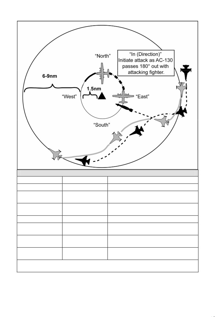
Wheel Communication Example
AC-130
CAS Aircraft
Explanation
9-Line
“Ready”
“Ready” signifies execution start
“South” (or East,
North, West)
“10 seconds to
Assurance that CAS aircraft see the
“Contact / Tally”
mark”
correct target
“Visual”
Required call prior to roll in.
“In Hot / Dry
Fighter is rolling in to attack.
(JTAC
(Direction)”
provides final clearance authority.)
“Weapon away,
XX seconds until weapon impact. AC-130
(XX) seconds”
cease firing on the same target
CAS aircraft is repositioning to the wheel
“Off Hot / Dry”
post attack
Note: Call “ALTITUDE” only if passing through AC-130 altitude. Expect AC-130 to call
“COLD.” Requires attacker to call “CLEAR” once deconfliction is assured.
Figure 10. AC-130 Integration in the Wheel
Dec 2007 FM 3-09.32/MCRP 3-16.6A/NTTP 3-09.2/AFTTP(I) 3-2.6
53

Figure 11. AC-130 Integration with IP-to-target Run-in
54 FM 3-09.32/MCRP 3-16.6A/NTTP 3-09.2/AFTTP(I) 3-2.6 Dec 2007

Figure 12. AC-130 Opposite Sector Attack
Dec 2007 FM 3-09.32/MCRP 3-16.6A/NTTP 3-09.2/AFTTP(I) 3-2.6
55

Warning: The words “CLEARED” or “ENGAGE” will only be used
when ordnance is actually to be delivered. Use standard radio calls to
the maximum extent possible. This will reduce the chance of dropping
ordnance on dry passes and reduce the risk of fratricide.
Abort Call Illustration
The JTAC call sign is “NAIL 11”, the CAS flight is “SPIKE 41.” SPIKE 41 flight has
chosen abort code “BR” (authenticated “D”).
Radio Call
Action Taken
(During the CAS check-in briefing): “Nail
Nail 11 notes the correct reply for “BR” is
11, this is Spike 41, abort code Bravo
“D”
Romeo.”
(The JTAC calls for an abort): “Spike 41,
Spike 41 aborts the pass.
Nail 11, Abort Delta, Abort Delta, Abort
Delta”
Note: Some NATO countries use “STOP” rather than “ABORT.” Controllers
must verify procedures in use.
Figure 13. Abort Call Illustration
5. Joint Terminal Attack Controller Brevity Codes
a. ABORT - Directive call to cease action/attack/event/mission. Abort the
pass. Do not release ordnance. Abort code should be included with the
ABORT transmission.
b. CLEARED HOT - Ordnance release is authorized in Type 1 or 2 terminal
attack controls.
c. CLEARED TO ENGAGE - JTAC Type 3 control clearance. Attack aircraft
flight leaders may initiate attacks within the parameters imposed by the
JTAC. Attack platforms will provide a “Commencing Engagement” call prior
to engaging targets and an “Engagement Complete” call to JTAC, indicating
completion of ordnance release.
d. CONTINUE - Continue present maneuver. Does not imply a change in
clearance to engage or expend ordnance. Used to acknowledge aircraft
without providing clearance to release ordnance.
e. CONTINUE DRY - Continue present maneuver, ordnance release not
authorized. Used to provide approval to aircraft to continue the pass without
expending ordnance during Type 1, 2, or 3* controls. (*JTAC must use
“Type 3, Continue Dry” for dry Type 3 controls.)
6. Electronic Attack / Call for Electronic Fires
a. Electronic attack (EA) involves the use of electromagnetic (EM) energy,
directed energy, or antiradiation weapons to attack personnel, facilities, or
equipment with the intent of degrading, neutralizing, or destroying enemy
combat capability and is considered a form of fires. EA can be targeted
against very specific portions of the radio frequency (RF) spectrum to obtain
the needed effects. For more detailed information on EA, see appendix H
56 FM 3-09.32/MCRP 3-16.6A/NTTP 3-09.2/AFTTP(I) 3-2.6 Dec 2007
(classified SECRET) on the ALSA classified website,
(1) Virtually any EM sensor utilizing the RF spectrum is potentially
vulnerable to electronic attack. With the proper electronic support,
particularly signals intelligence, an appropriate EA system can be
programmed to influence the enemy’s use of the electromagnetic
spectrum at a time and place of our choosing.
(2) Since both friendly and enemy forces and infrastructure utilize the RF
spectrum for communications, navigation, sensing, information storage,
and processing, proper coordination measures are necessary to effect
enemy systems of interest without interference with friendly systems.
Without proper RF deconfliction, friendly ground jammers would interfere
with JTAC communications. For further info on RF targets and
information on deconflicting EA with friendly communications, see
appendix H as referenced above.
(3) EA is the primary joint nonlethal fire support means.
b. EA terms and definitions:
(1) Jamming Control Authority (JCA): The JCA, appointed by the joint force
commander, conducts on-station, real-time coordination and
deconfliction of jamming efforts. The JCA monitors the electromagnetic
spectrum, assesses effects on friendly and enemy forces, and maintains
contact with EA assets to provide direction and coordination of EA
efforts. Jamming will not normally be conducted without approval of the
JCA. JCA can be, and usually is, delegated well down the chain of
command. JCAs will be designated in the SPINS.
(2) Joint Restricted Frequency List (JRFL): The JRFL is a time and
geographically-oriented listing of “Taboo”, “Protected”, and “Guarded”
functions, nets, and frequencies designed to minimize frequency
conflicts between friendly emitters and friendly jamming equipment. It
consists of a listing of prioritized frequencies essential to the conduct of
the battle and restricted from targeting by friendly forces. Requests for
deviation from JRFL requirements may be granted depending on the
situation.
(a) TABOO: Frequencies of international safety and distress systems
that cannot be jammed.
(b) PROTECTED: High priority friendly frequencies of systems that
should not be jammed. This is not a list of all friendly C2.
(c) GUARDED: High priority enemy frequencies that are being used for
collection by intelligence assets. Intelligence gain/loss determinations
need to be done on these frequencies prior to jamming.
(d) CEASE BUZZER: “Cease Buzzer” is the cessation of jamming
certain radio frequencies.
(e) CEASE MUSIC: “Cease Music” is the cessation of all jamming
activities.
Dec 2007 FM 3-09.32/MCRP 3-16.6A/NTTP 3-09.2/AFTTP(I) 3-2.6
57

c. Commercial Off the Shelf (COTS) emitters targeted by EA:
Table 14. Commercial Off the Shelf Emitters Targeted by Electronic
Attack
System
Frequency (MHz)
HF Automatic Link Engagement Voice
1.5 - 30
Low Very High Frequency Voice
30 - 88
Low Very High Frequency Frequency Hoppers
30 - 88 / 225 - 400
VHF / UHF Voice
88 - 300 / 300 - 520
Air / Ground Controlled Intercept
100 - 500
Long Range Cordless Phone
240 - 270 / 370 - 400
Frequency Modulation Repeaters
100 - 300 / 300 - 500
Trunked Mobile Radio
100 - 520
Radio Broadcast
88 - 108
Television Broadcast
64 - 450
GSM 900 (Cellular)
890 - 960
Digital Cellular System 1800
1710 - 1880
Troposcatter
475 - 625 / 4400 - 5000
LOS Radio Relay
138 - 7500
Thuraya (Mobile Satellite phone)
1525 - 1560
INMARSAT (Mobile Satellite phone)
1525 - 1560
IRIDIUM (Mobile Satellite phone)
1616 - 1626.5
VSAT (Remote Telephone and Internet)
3000 - 4000 / 11000
GLOBALSTAR (Mobile Satellite phone)
2483.5 - 2500
d. Electronic fires support falls within three operational timelines:
1) preplanned, 2) preplanned on-call, and 3) immediate.
e. Requesting airborne EA support for ground operations is similar to
requesting CAS. Request EA effects via normal request process (JTAR /
ASR - DD Form 1972) and provide the information below either in the
remarks section (Section 8) of JTAR or via theater specific EA Request
Format (EARF). The EARF (figure 14) needs to be completed and
forwarded through component chain of command to complement JTAR.
Table 15. Joint Tactical Air Strike Request Remarks Information
(Section 8)
1
Target Location
2
Prioritized Target Description and Jam Freqs
3
TOT (window)
4
JTAC / JCA Call Sign and Freq
5
Friendly Force Disposition (i.e., troop movement route)
6
Friendly Frequency Restrictions
7
Remarks
58 FM 3-09.32/MCRP 3-16.6A/NTTP 3-09.2/AFTTP(I) 3-2.6 Dec 2007

(1) Target Location: Coordinates (point or area) where effect is requested;
type of terrain (mountainous, urban, etc.).
(2) Target Description: RF system or device to be affected; frequency and
coverage desired (if known) listed in order of priority.
(3) TOT: Desired beginning time of effects (Zulu) and duration needed.
(4) JTAC / JCA Call Sign and Frequency: Primary communication
frequencies and back-up communication plan.
(5) Friendly Force Disposition: Friendly force locations and maneuver route.
(6) Friendly Frequency Restrictions: Prioritized “no-jam” friendly frequencies
(communications and UAS / weapons systems data-links).
(7) Remarks: Amplyfing information as required.
Electronic Attack Request Format
Requesting Major Supported Command:
Requesting Unit:
Contact Information: This person will be respons ble to verify that the EARF
has been approved before the mission starts and to relay the information to
the executing unit.
JTAR Number: Enter the corresponding JTAR number that will be submitted
with this EARF.
Concept of Operation: Descr be the concept of operations. This will include
objective, forces used, timeline of mission, and coordination efforts required
for mission success. Relate the impact of mission success to specific
objectives for the integrated tasking order.
EA Concept of Operations: Descr be the role EA will play, timelines for EA
effects, and the objective for EA effects.
Cease Buzzer (Jamming) Procedures: This should be directly as stated in
SPINS. If other procedures are to be used, details establishing JCA must be
specific and a way for JCA and the EA asset to communicate must be
specified. Ground-to-ground procedures for request must be established as
well. Any asset can request a cease-buzzer, but only the JCA can direct EA
systems to turn off jamming.
Friendly Frequency Evaluation:
Target Communication
Systems/Frequencies to be
Details of Systems:
Jammed/Denied:
Target Location:
Jamming date-time group(s): From - To, in Zulu
Type of EA Requested: Preplanned - Scheduled / On-Call
This form is SECRET when filled in.
Figure 14. Electronic Attack Request Format
7. Tactical Show of Force
a. A tactical show of force is an operation designed to demonstrate friendly
forces resolve that involves increased visibility of CAS aircraft in an attempt to
Dec 2007 FM 3-09.32/MCRP 3-16.6A/NTTP 3-09.2/AFTTP(I) 3-2.6
59

defuse a specific situation that, if allowed to continue, may be detrimental to
friendly forces interests or objectives.
b. Plan shows of force in the same manner as a low altitude CAS mission.
Clearance into the designated show of force area is “Continue.” Low altitude
release of flares and supersonic speeds may require approval from higher
command authority.
8. North Atlantic Treaty Organization Procedures
Table 16. North Atlantic Treaty Organization Standard Rear Briefing
Rear Briefing. Briefing information passed by a rear briefing agency should normally be
divided into what is mandatory and what may also be required by the tactical situation.
The briefing should comprise the following items in the order shown:
1. Mandatory Items:
a. Target location in grid or lat/long with target elevation in feet above mean sea level
(mandatory readback and recording of actions).
b. Target description (may include advisory or mandatory attack headings).
c.
“No friendlies within” distance or nearest friendly location (mandatory readback and
record action).
2. Additional Items:
a. Target Area Threats
b. Navigation Hazards
c. Hazards
d. Other items
Sample North Atlantic Treaty Organization Close Air Support Worksheet
(Check-in Information)
Call Sign
Mission #
Authentica ion
Aircraft Number
and Type
Ordnance
Position
Playtime
Abort Code
LST / Datum / NVG
LST / Datum / NVG
LST / Datum / NVG
Figure 15. Sample North Atlantic Treaty Organization Close Air Support
Worksheet
60 FM 3-09.32/MCRP 3-16.6A/NTTP 3-09.2/AFTTP(I) 3-2.6 Dec 2007

Format 17. North Atlantic Treaty Organization Close Air Support
Check-in Briefing
Permissive Environment
Aircraft: “_________________, this is ______________________”
(Controller Call Sign)
(Aircraft Call Sign)
Identification / Mission Number: “___________________________”
Authentication: “Authenticate ____________”
(JTAC should authenticate before continuing with the brief.)
Number and Type of Aircraft: “_______________________”
Ordnance: “_______________________”
Position: “________________________”
Time on Station: “_______________________”
Rear Briefing Identifier: “____________________”
Abort Code: “_________________”
Nonpermissive Environment
Aircraft: “_________________, this is ______________________”
(Controller Call Sign)
(Aircraft Call Sign)
Identification / Mission Number: “___________________________”
Authentication: “Authenticate ____________”
JTAC should authenticate before continuing with the brief.
“As fragged with briefing
” (Rear Briefing Identifier)
Dec 2007 FM 3-09.32/MCRP 3-16.6A/NTTP 3-09.2/AFTTP(I) 3-2.6
61

Format 18. North Atlantic Treaty Organization
15-Line Controller to Attack Aircraft Briefing
Mission Call Sign _____________ Abort Code _______________
- Items A through J are mandatory, K through O are optional.
- Items A, D, G, and H (Bold) are mandatory readback (*) even if “None.”
- Headings and bearings are Magnetic unless True is requested.
A*. IP “______________________________________________”
B. Bearing “__________________________________________”
C. Distance “_________________________________________”
D*. Target Location “___________________________________”
(Grid or Lat/Long)
E. Target Elevation “___________________________________”
F. Target Description “__________________________________”
G*. Attack Heading “____________________________________”
H*. Friendly Forces “____________________________________”
I. Attack Time (TOT / TTT) “______________________________”
J. Attack Clearance JTAC Call Sign “________” TAD “________”
K. Target Indications:
1. Reference Point
2. Smoke
3. Light / Mirror
4. Laser Code / Laser to Target Line (in degrees)
5. Beacon:
Frequency
Bearing (in degrees)
Distance (in meters)
Elevation (in feet MSL)
L. Threats “__________________________________________”
M. Weather (if significant) “______________________________”
N. Hazards “__________________________________________”
O. Egress “___________________________________________”
62 FM 3-09.32/MCRP 3-16.6A/NTTP 3-09.2/AFTTP(I) 3-2.6 Dec 2007

9. Other Briefing Formats
a. Casualty Evacuation (CASEVAC) Procedures. This portion of JFIRE is not
intended to provide in-depth detail on the CASEVAC briefing, but to provide
familiarity to aircrew if required to relay information or to assist in some manner.
Format 19. Casualty Evacuation Briefing
Line
Item
Explanation
1
Location of Pickup
Encrypt the grid coordinates
Radio freq, Call sign,
Call sign and suffix may be transmitted in
2
and Suffix (if used)
the clear
A - Urgent
B - Surgery
# of Patients
3
C - Priority
by Precedence
D - Routine
E - Convenience
A - None
Special Equipment
B - Hoist
4
Required
C - Extraction equipment
D - Ventilator
L + # of patients (Litter)
5
# of Patients by Type
A + # of patients (Ambulatory)
N - No enemy in area
P - Possible enemy in area, use caution
6
Security of Pickup Site
E - Enemy in area, approach with caution
X - Enemy in area, armed escort required
A - Panels
B - Pyrotechnic signal
Method of Marking
7
C - Smoke signal
Pickup Site
D - None
E - Other
A - US military
B - US citizen
Patient Nationality and
8
C - Non-US military
Status
D - Non-US citizen
E - Enemy prisoner of war
C - Chemical
B - Biological
9
CBRN Contamination
R - Radiological
N - Nuclear
Dec 2007 FM 3-09.32/MCRP 3-16.6A/NTTP 3-09.2/AFTTP(I) 3-2.6
63

b. Airdrop Procedures
Format 20. Airdrop Briefing (Aerial Resupply)
Do not transmit line numbers. Units of measure are standard unless briefed.
Lines 3 (C-17 only), 4, 5, and 7 (restrictions only) are mandatory readback (*).
JTAC may request additional readback.
JTAC: “________________, this is ______________ for airdrop control.”
(Aircraft Call Sign)
(JTAC Call Sign)
1. Drop Zone (DZ) Visual Description: “____________________________”
(Open north/south field, Road ‘T’, etc.)
2. Location of Friendlies:
“_______________________________________”
(from DZ, cardinal direction and distance in meters)
Position marked by: “_________________________________________”
3.* IP / Heading / Distance: “____________________________________”
(*Degrees magnetic, IP-to-DZ, when required)
Offset: “____________________________________________________”
(Left / Right, when required)
4.* Point of Impact Location: “__________________________________”
(Lat/Long, grid to include map datum [e.g., WGS-84])
5.* Point of Impact Elevation: “__________________________________”
(in feet above MSL)
6. Point of Impact Marking: “_____________________________________”
(Code letter, mirror, IR strobe, IR chemstick, etc.)
7.* Restrictions: “_____________________________________________”
Remarks in Restrictions as appropriate.
[Applicable ground threats to aircraft / suppression coordinated / hazards
(terrain, towers) / surface winds / estimated ceiling and visibility / GTL / final
attack heading / additional friendly aircraft in the area / # of container delivery
system (CDS) bundles / type CDS bundles / egress direction (if different than
assigned ingress heading).]
Time on Target (TOT): “
” or Time to Target (TTT): “
”
Note: When identifying position coordinates for joint ops, include map data.
Grid coordinates must include 100,000 meter grid identification.
64 FM 3-09.32/MCRP 3-16.6A/NTTP 3-09.2/AFTTP(I) 3-2.6 Dec 2007
(1) Notes on Airdrop Format:
(a) Strictly intended for time-sensitive preplanned airdrop (aerial
resupply) operations only.
(b) C-130: Line 3 is optional, brief according to situation.
(c) C-17: If rectangular DZ, heading is required in Line 3. Optional for
circular DZ.
(d) DZ - area for expected aerial resupply.
(e) Point of Impact - requested specific aerial resupply point of impact.
(f)
If required, direct aircraft to call 1 min and/or 30 seconds to release.
Release authority is the ground controller or briefed ground signal.
Utilize “CLEARED TO DROP” via radio.
(g) No abort code; utilize “NO DROP” via primary radio for airdrop
cancellation.
(h) Absolute minimum information required to conduct airdrop (aerial
resupply): Lines 3 (C-17 only), 4, 5, and 7 (restrictions only).
(2) Planning Considerations:
(a) Threat permitting, hold airlift aircraft at low-medium altitude outside of
the objective area. Response time dependent on hold point location,
but expect 20 minutes.
(b) Point of impact should be 200 yards from nearest friendlies.
(c) Refer to AFI 13-217, Drop Zone and Landing Zone Operations, for DZ
size. Expected impact area for C-130 low altitude delivery of 16 x
CDS is 100 yards wide by 200 yards long.
(d) If able, minimize the effect of terrain on ingress/egress routing due to
airlift aircraft performance limitations.
(e) This airdrop briefing format can be used for high altitude and/or Joint
Precision Aerial Delivery System.
Dec 2007 FM 3-09.32/MCRP 3-16.6A/NTTP 3-09.2/AFTTP(I) 3-2.6
65

c. Reconnaissance / Surveillance Procedures
Format 21. Reconnaissance / Surveillance Briefing
Do not transmit line numbers. There are no mandatory readback items.
However, JTAC may request readback of certain items.
JTAC: “________________, this is ______________ , call when ready for
(Aircraft Call Sign)
(JTAC Call Sign)
reconnaissance/surveillance briefing.”
Aircrew: “Ready to copy”
1. Reference Point: “__________________________________________”
(IP, Anchor Point, Start Point, etc.)
2. Description:
“______________________________________________”
(What to look for? What is the Gnd commander objective?)
3. Location and Elevation: “______________________________________”
(Point-to-point, route recce, area search, NAI coordinates/elevation)
4. Friendlies in area: YES / NO “__________________________________”
(Amplifying Data)
5. Airspace Control Measures: “__________________________________”
(ACA, Arty, Sector/Altitude Restrictions, etc.)
6. Remarks (as appropriate): “___________________________________”
- Hazards to Aviation
- Weather
- ROVER Frequency
- Time to Accomplish
- Reporting Instructions
Note: When identifying position coordinates for joint ops, include map data.
Grid coordinates must include 100,000 meter grid identification.
(1) Notes on Reconnaissance / Surveillance Briefing Format:
(a) JTACs will use this briefing to pass information rapidly to aircrew for
use with fixed- and rotary-wing aircraft which are given immediate
reconnaissance/surveillance taskings. It is used for all threat
conditions and does not dictate the tasked aircrew’s tactics.
(b) The brief must be accurate, concise, and executed quickly. Map
datum must be considered when determining reference and search
point / area coordinates. The mission brief could change during the
mission. Only line items which change must be passed by the JTAC
to the aircrew. Others may be stated “as briefed.”
(c) This briefing does not provide clearance to employ ordnance. It is
NOT to be used to brief aircrew for the purpose of conducting an
attack. The CAS 9-Line (Format 15) is to be used to prepare aircrew
for a CAS attack.
66 FM 3-09.32/MCRP 3-16.6A/NTTP 3-09.2/AFTTP(I) 3-2.6 Dec 2007