Military reference books and manuals (2009-2023, Volume 1) - page 33
Electronic Warfare Fundamentals
(5)
interface with the land integrated support
station (LISS) to enable 2nd level collation
of new signals;
(6)
interaction with standard electronic
parameter databases such as the Canadian
Forces EW Database (CFEWDB) and the
NATO Emitter Database (NEDB);
(7)
recording; and
(8)
interface directly with the EW analysis
component.
d.
ECM Capability. The ECM component consists of
a number of dedicated detachments and modular
equipment, which may be integrated with ESM
detachments for attacking both communication and
non-communications targets, either in a deliberate or
a surgical fashion. ECM detachments require the
following capabilities:
(1)
platform independence to the greatest
extent possible;
(2)
the ability to attack both communications
and radar frequency bands;
(3)
upgradeable; and
(4)
capable of performing a range of ECM
tasks, including but not limited to electronic
masking, spoofing, deception and jamming.
e.
Analysis Capability. The analysis component of an
EW unit converts the data and information collected
by the EW sensors into a “single source” product,
EW summaries (EWSUMs) or tactical reports
(TACREPs). This component consists of specially
trained personnel and specialized equipment. It can
be as simple as an analyst working along side a
search/intercept operator. Analysis is usually
conducted in a distributed fashion, with various
baseline detachments, the SIGINT EW operations
centre (SEWOC) and the EW coordination cell
(EWCC) each adding layers of analytical refinement
B-GL-358-001/FP-001
23
Electronic Warfare
to the end product. The component has the
following capabilities:
(1)
the capability to receive sensor data;
(2)
tools to assist the analyst to process the
data;
(3)
EW trained analytical personnel;
(4)
the ability to create, hold and secure highly
classified materials and databases;
(5)
access to other intelligence databases;
(6)
the ability to interface directly with ESM
and ECM components; and
(7)
the ability to interface directly with
national-level SIGINT databases.
f.
EW C2IS Capability. EWCC, EWOC and EW
liaison officer (EWLO) staffs at supported formation
headquarters (as required) provide for the command
and control of EW assets. The EW control and
analysis centre (EWCAC) component is an EW
specific C2IS consisting of personnel, information
systems and physical facilities that provide the
means to exercise command and control in forming
the EWCC and EWOC. This component is
supported by an integral signal organization of
appropriate size. The EW C2IS capability must
support the following:
(1)
dispersed deployment of EW assets
throughout the AO;
(2)
interoperability with the Land Force
Command and Control Information System
(LFC2IS);
(3)
the capability of handling highly classified
information; and
(4)
the capability of supporting timely
transmission of data from the sensor to the
end-product customer without requiring
either hard-copy or “air gapping.”
24
B-GL-358-001/FP-001
Electronic Warfare Fundamentals
g.
Combat Service Support Capability. The combat
service support (CSS) component provides the CSS
necessary for EW operations. Electronic warfare
organization are supported as other units of a
formation are and in accordance with sustainment
doctrine.27 Electronic warfare organizations have
specialist maintenance capabilities to support
specialized fleets of EW equipment. Some
equipment provided by the national/strategic level
authorities will be maintained by those agencies and
not through the integral LF EW unit CSS
component.
SECTION 8
EW SUPPORT
14.
In order to provide the best support to operational
commanders, deployed EW units must take advantage of national and
international capabilities to augment limited resources. A deployed
LF commander will receive EW support from three areas:
a.
organic EW resources;
b.
resources from other nations in theatre (force level
EW capabilities); and
c.
Canadian national/strategic resources.
15.
Organic EW resources provide the access to the national
signal intelligence system. With limited resources, it is unlikely that
LF organic resources will be able to provide all the EW information
necessary for operations. EW units cannot provide their full potential
combat effect without access to national signal intelligence systems.
16.
Theatre EW units, depending on their tasks, may be able to
provide both ESM and ECM support. This support will be
coordinated by the EWCC. There may be national limitations on the
provision of this support.
17.
Canadian Forces Information Operations Group is to provide
a CF level signal intelligence capability for the provision of databases,
27 For more information see B-GL-300-004/FP-000 Sustainment and
supporting sustainment system manuals.
B-GL-358-001/FP-001
25

Electronic Warfare
specialized equipment, specialist operators and sanctuary operations.28
Also, CFIOG will provide access, through the Canadian Security
Establishment (CSE), to resources and information from allied nations
and, via the land integrated support station (LISS), to the Canadian
Forces EW Database (CFEWDB). Lastly, CFIOG will force generate
a signals intelligence satellite support element (SSE) to augment
deployed LF EW assets on an as required basis.
Figure 2-2: National to Tactical EW Op Support
18.
It is important to note that augmentation of a SSE results in
the creation of either a SEWOC and/or a SEWCC capability as an SSE
will locate with either the EWCC or EWOC.
28 Sanctuary (or split based) operations is a term used to describe operations
that are being conducted from a safe area (normally out of theatre in Canada)
to directly support operations in theatre.
26
B-GL-358-001/FP-001

Electronic Warfare Fundamentals
Figure 2-3: SEWOC
B-GL-358-001/FP-001
27
Electronic Warfare
Figure 2-4: SEWCC
19.
At the LF level, the LISS provides a Land EW operational
support (LEWOS) capability to deployed LF EW systems. An
example of this is the provision of a start state radar database for
ELINT ESM ops during pre-deployment preparations.
SECTION 9
ORGANIZATION: FORCE GENERATION
20.
The 2 EW Squadron is organized along mission-oriented
lines and is capable of deploying in a scalable fashion. Troops within
the squadron are tailored to respond to tasks across the spectrum of
conflict, with one troop specializing in View 1 tasks and those View 2
tasks requiring armoured protection and a second troop specializing in
View 2 tasks and/or View 1 tasks requiring additional mobility, low
profile or deployability. While the EW Squadron complete can
provide effective EW support for up to a division or two brigade group
sized deployments simultaneously,29 deployments are based on case-
by-case assessment of mission requirements and the EW target
environment.
21.
There are two broad organizational paradigms for EW
employment:
a.
light EW, and
29 Simultaneous deployment of both troops must take into consideration issues
such as sustainment.
28
B-GL-358-001/FP-001
Electronic Warfare Fundamentals
b.
heavy EW.
LIGHT EW
22.
Light EW assets have the full spectrum of operational
capability and are mounted in wheeled soft-skinned vehicles thus
having the ability to operate dismounted to a limited degree.
Logistical limitations of the platforms employed may dictate a slightly
degraded capability that is offset by increased mobility and reduced
logistical support requirements.
HEAVY EW
23.
Heavy EW assets are equipped with wheeled armoured
sensor platforms. Heavy EW may have an increased technical
capability due to the increased load-carrying capacity of the platform
and provide increased operator protection. Heavy EW has increased
logistic support requirements.
SECTION 10
ORGANIZATION: FORCE EMPLOYMENT
24.
For all deployments, subject to resource constraints and based
on the assigned mission, the EW team/detachment/troop/squadron will
be formed on a grouping of the fol building block functions/entities:
a.
EWCC or SEWCC;
b.
EWOC or SEWOC;
c.
EWLO;
d.
mobile EW team (MEWT);
e.
ECM; and
f.
CSS.
A MEWT is a grouping of EW capability, usually ESM, at the lowest
level, formed to meet a mission requirement. It can be an existing
ESM detachment, an ESM detachment augmented with intelligence
analysis capability or a grouping of both an ESM and ECM
detachment together. A MEWT grouping is mission dependant.
25.
The EW Squadron complete would normally deploy the
following:
B-GL-358-001/FP-001
29

Electronic Warfare
a.
a main and alternate SEWCC—this depends if there
is an alternate formation headquarters;
b.
one or more EWLO detachments;
c.
a main and alternate operation centre (SEWOC) to
provide a firm base for continuous search, intercept,
analysis and communications DF tasking;
d.
two light and/or heavy ESM baselines of normally
four detachments each, including a mobile
detachment specializing in EW/spectrum
reconnaissance;
e.
four ECM/jamming detachments; and
f.
a CSS echelon.
Figure 2-5: EW Squadron Deployment Order of Battle
26.
As deployments can be scaled to specific mission
requirements, the total number of options is extensive. The following
list of examples is not exhaustive:
a.
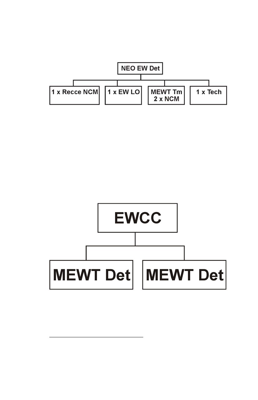
EWLO. Small-scale short-term deployments, such
as a non-combatant evacuation operation (NEO),
might be provided with a single vehicle (or man-
pack) detachment, which is capable of providing
30
B-GL-358-001/FP-001
Electronic Warfare Fundamentals
EW liaison, advice, connectivity to national or allied
assets and a limited capability to perform ESM.30
Figure 2-6: NEO EW Team
b.
EWCC/MEWT. A two- or three-vehicle grouping
capable of providing EW liaison, advice and
connectivity to national or allied assets, a full-time
presence at the ISTAR table if required, and a team
capable of mobile ESM operations, either vehicle-
mounted or foot borne, to carry out EM spectrum
reconnaissance and provide target situational
awareness and threat warning to the supported
commander.
Figure 2-7: EWCC/MEWT
c.
Rapid Deployment Troop. EWCC, EWOC, one
EWLO team (capable of acting as EWOC alternate),
a wheeled vehicle baseline capable of full spectrum
30 The level of ESM that can be provided by a single detachment is limited to
essential force protection and short-term warning.
B-GL-358-001/FP-001
31
Electronic Warfare
ESM and limited ECM and integral specialist
technical support.
Figure 2-8: Rapid Deployment EW Troop
32
B-GL-358-001/FP-001
Electronic Warfare
CHAPTER 3
COMMAND AND CONTROL OF ELECTRONIC WARFARE
SECTION 1
GENERAL
1.
When speaking of command and control of electronic warfare
(EW), this normally refers to specialist EW units/detachments within
formations. Electronic warfare units provide formation commanders
with capabilities to conduct EW support measures (ESM) and
electronic countermeasures (ECM) operations. All units and
formations conduct electronic protective measures (EPM) with EW
units providing specialist advice. Electronic warfare must be
coordinated centrally at each level of command. This does not prevent
the allocation of EW capabilities to subordinate formations and units.
Internal to an EW unit, command and control is exercised via two
distinct entities—the EW coordination cell (EWCC), which exercises
command on behalf of the EW unit commander, and the EW
operations centre (EWOC), which exercises operational control of the
EW assets in accordance with command direction.
SECTION 2
COMMAND OF EW
2.
Electronic warfare unit commanders exercise command over
their organic EW assets and, depending on the command
relationship,31 exercise control (on behalf of the commander) of
additional EW assets assigned. The EW commander is also the arms
adviser to the commander on EW matters.
3.
The EWCC is located at the tactical headquarters and acts as
the EW unit commander’s ops staff. This coordination is primarily in
the form of direction with regard to movement and allocation of EW
assets in support of specific units during different phases of formation
operations.
31 B-GL-300-003/FP-000 Land Force Command provides details of various
command relationship under which forces can be assigned.
B-GL-358-001/FP-001
33
Electronic Warfare
SECTION 3
ELECTRONIC WARFARE COORDINATION CELL
4.
The EWCC is the focal point for all EW activities within a
given level of command. The supporting EW unit normally provides
the EWCC. Each level of command that has EW assets allocated will
have an EWCC. The EWCC performs the following functions:
a.
develop the EW plans to support the commander’s
operation and intelligence, surveillance, target
acquisition and reconnaissance (ISTAR) plan;
b.
coordinate ESM and ECM activities with other
combat capabilities within the formation;
c.
coordinate ESM and ECM activities with higher and
flanking formations;
d.
provide specialist EW advice to the commander and
other staff, including EPM;
e.
direct ESM and ECM activities on behalf of the EW
commander;
f.
control ECM operations on behalf of the EW
commander;
g.
provide ESM results in support of the ISTAR
system; and
h.
provide EW operational support (EWOS32) through
liaison with higher and national level organizations.
5.
Coordination of EW activities across various levels of
command is critical. This prevents the duplication of effort and
enhances the sharing of EW information. The chain of command
takes precedence over any EW technical control. The senior
formation EWCC has technical control of all EW activities. Figure
3-1 illustrates the parallel chain of command and control within a
solely national context.
32 EWOS consists of the provision and maintenance of EW databases in
support of EW operations undertaken by the Land Integrated Support Station
(LISS).
34
B-GL-358-001/FP-001
Command & Control of EW
Figure 3-1: EW Coordination
6.
In the context of joint and multinational operations, the same
technical control relationship would occur. The joint EWCC would
exercise technical control over the Land component EWCC (as well as
those of the Air and Maritime elements). Canadian LF formations will
normally be allocated to an allied formation for operations. The allied
formation EWCC is responsible for the coordination of all EW
activities within the formation. Technical control and passage for EW
information to other nations will be based on national agreements and
policies. Figure 3-2 is illustrative of this arrangement from a NATO
context.
B-GL-358-001/FP-001
35

Electronic Warfare
Figure 3-2: JFC EWCC Integration and Relationships
ELECTRONIC WARFARE OPERATIONS CENTRE
7.
As previously stated, the EWOC exercises operational real
time control of the formation EW capability specifically with regard to
ESM in accordance with the EW unit commander’s direction. The
primary function of the EWOC is to control the ESM system as it
executes search, intercept and direction-finding tasks. It should be
noted that an EWOC could vary both in location and manning. In the
traditional sense the analysis function is centrally collocated with an
intercept capability to form a large EWOC complex separate from
both ESM baselines and the EWCC. With the formation of mobile
EW teams (MEWTs) with analysts pushed forward into ESM location
and exercising first level analysis of forward search, intercept and DF,
the paradigm of the EWOC as a centralized physical entity needs to be
reconsidered. With the deployment of MEWTs, the EWOC is more a
dispersed function then a centrally located detachment. As a physical
36
B-GL-358-001/FP-001

Command & Control of EW
grouping, albeit with reduced manning, the EWOC will always exist.
However, with the deployment of MEWTs, it is likely to collocate
either with the EWCC or with the all source cell at formation HQ.
Ground truth will dictate the implemented EWOC solution. Note the
addition of a satellite support element (SSE) capability to an EWOC
renders it a SEWOC.
Figure 3-3: Centralized SEWOC Deployment
B-GL-358-001/FP-001
37
Electronic Warfare
Figure 3-4: Dispersed SEWOC Deployment with Fwd Search,
Intercept, DF and Analysis
ELECTRONIC WARFARE LIAISON OFFICERS
8.
Electronic warfare liaison officers (EWLOs) are normally
allocated from the formation EW unit to subordinate formations that
do not have an organic EW unit. The purpose is to allow subordinate
formations and units access to the capabilities of the EW system, in
particular, ESM information and ECM. If a subordinate formation is
allocated EW resources, an EWCC is provided to support that
formation headquarters.
38
B-GL-358-001/FP-001
Electronic Warfare
CHAPTER 4
THE OPP, IPB, TARGETING, ISTAR AND EW PROCESSES
SECTION 1
THE OPERATIONAL PLANNING PROCESS
1.
Formation headquarters (HQs) use the operational planning
process (OPP) to produce a plan based on the mission, concept and
intent of the higher commander. The intelligence preparation of the
battlefield (IPB) process and the targeting process support the OPP.
The OPP is a six-step process:
a.
Receipt of Tasks. The formation HQ normally
receives its tasks as a warning order, operations
order or fragmentary order from the higher
formation. The receipt of the tasks initiates a new
planning cycle.
b.
Orientation. In this step the commander conducts
his mission analysis and prepares his guidance. The
commander's guidance will include commander's
critical information requirements (CCIRs). Priority
intelligence requirements (PIRs) are the component
of CCIRs that provides guidance to the overall
intelligence, surveillance, target acquisition and
reconnaissance (ISTAR) effort and by extension the
electronic warfare support measures (ESM) effort.
c.
Develop Courses of Action. The staff develops
courses of action (COA) based on the information.
The IPB process develops possible adversary COA
and questions for the ISTAR system. The staff then
compares COA by means of a war game. The
electronic warfare coordination cell (EWCC) would
support the ISTAR system in helping to answer
questions from IPB by directing ESM activities and
obtaining any available signals intelligence
(SIGINT) from other sources.
d.
Decision. The staff presents the results of COA war
game to the commander for a decision on which
COA to develop into a plan.
e.
Plan Development. Another war game is
conducted to refine the selected COA and develop
the decision support template (DST), the
B-GL-358-001/FP-001
39
Electronic Warfare
synchronization matrix and high payoff target list
(HPTL). The targeting process produces the attack
guidance matrix (AGM). The EWCC supports the
targeting process with coordination of electronic
countermeasures (ECM). The result of this step is
the production of an order.
f.
Plan Review. The coordination of the details of the
plan with subordinate units is conducted during this
step. The EWCC coordinates the electronic warfare
(EW) plan with higher and lower formations as
necessary.
SECTION 2
ELECTRONIC WARFARE AND THE INTELLIGENCE
PREPARATION OF THE BATTLEFIELD PROCESS
2.
The IPB process provides a continuous analysis of the
adversary, weather and terrain. The result of the process is the
information collection plan (ICP). The process has four steps:
a.
Define the Battlefield. The staff refines the area of
operations (AO) and defines the area of intelligence
responsibility (AIR) based on the higher formation
orders and the commander's initial planning
guidance.
b.
Describe the Battlefield Effects. The G2 collects
information about the battlefield or updates
information provided by other sources. The effects
of terrain and weather on the AO are also evaluated.
c.
Evaluate the Threat. The G2 assembles all
available information on the adversary and prepares
doctrinal and event templates.
d.
Determine Threat COA. The G2 prepares threat
COA based upon the available information.
3.
The EWCC does not normally participate in IPB, however,
the IPB product, the ICP, provides direction to the EWCC for ESM
through the ISTAR CC. If required, the EWCC would provide advice
on the employment of ESM assets to support the ICP. The IPB
process is a useful tool for the EWCC in preparation for ESM
operations.
40
B-GL-358-001/FP-001
The OPP, IPB, Targeting, ISTAR & EW Processes
SECTION 3
ELECTRONIC WARFARE AND THE TARGETING PROCESS
4.
Targeting is defined as “the process of selecting targets and
matching the appropriate response to them taking account of
operational requirements and capabilities.”33 The targeting process
assists the commander by determining which targets are to be acquired
and attacked, when they are to be attacked, and what is required to
defeat the target. A target is an adversary function, formation or
equipment, facility or terrain planned for destruction, neutralization or
suppression in order to delay, disrupt, divert, limit or destroy the
adversary.34 Targeting links the commander, the sensors and the
engagement systems. The targeting process has four functions:
a.
Decide. Decide is the cornerstone of the targeting
process and requires close coordination between the
commander and the intelligence, plans, operations
and targeting team elements. The process begins
with receipt of a mission, whether assigned by
higher headquarters or deduced by the commander.
The commander, with input from his staff, analyses
the mission and considers the tasks that must be
performed. Targeting priorities must be addressed
for each phase or critical event of an operation.
b.
Detect. Detect is the next critical step in the
targeting process. The G2 is the main figure in this
step as he coordinates the effort to detect high
payoff targets (HPTs) identified in the decide
function. To ensure there is no duplication of effort,
specific direction is given to target acquisition
systems capable of detecting high priority targets.
Information needs are expressed as priority
intelligence requirements (PIRs) and information
requirements (IRs). The detect function is carried
out through the execution of the ICP.
c.
Deliver. The deliver function of the targeting
process executes the AGM and supports the
commander’s battle plan once the HPTs have been
33 AAP 6 NATO Glossary of Terms and Definitions.
34 B-GL-300-007/FP-001 Firepower Chapter 3.
B-GL-358-001/FP-001
41
Electronic Warfare
located and identified. During the detect function, it
is the target acquisition (TA) assets that have to be
managed. The deliver function provides the
framework for the efficient employment of firing
assets. The attack of targets must satisfy the attack
guidance developed during the decide function.
d.
Assess. Combat assessment is the determination of
the effectiveness of force employment during
military operations. It is composed of three
elements as follows:
(1)
Battlefield Damage Assessment (BDA).
BDA is the timely and accurate assessment
of damage resulting from the application of
military force, either lethal or non-lethal,
against a target. It provides commanders
with an estimate of the adversary’s combat
effectiveness, capabilities and intentions.
(2)
Munitions Effect Assessment (MEA).
This is used as the basis for
recommendations for changes to increase
the effectiveness of tactics, methodology,
weapon system selection, munitions and
weapon delivery patterns.
(3)
Recommendations for Re-attack. This
aspect considers the requirement for
another attack if the desired effect on the
target has not been achieved.
5.
The EW system is involved in the targeting process in two
ways. Firstly, ECM is integrated as an “engagement system” with all
of the other engagement systems at the commander’s disposal. The
EWCC, which is a member of the targeting team, is responsible for the
integration, tasking and control of ECM based on the targeting
priorities. The second way that the EW system is involved in the
targeting process is that the entire EW system is required to conduct its
own targeting process for effective ECM support.
6.
The EWCC with the targeting team conducts the decide
function for ECM. The targeting team will recommend the use of
42
B-GL-358-001/FP-001

The OPP, IPB, Targeting, ISTAR & EW Processes
ECM and the control measure35 to be in effect. The ESM provides the
detection function for ECM. This involves the collection of
information (in effect target acquisition) in sufficient detail to allow
for effective ECM. For example, determination that a specific
frequency is an artillery net and its general direction is sufficient
information to allow the EWCC to target that particular net. The
deliver function is conducted by the ECM detachments as directed and
coordinated by the EWCC. The ESM then provides the assess
function by determining if the ECM has been effective and
recommends new targets to the EWCC to ensure the ECM remains
effective.
Figure 4-1: EW in the Targeting Process
SECTION 4
THE ISTAR PLANNING PROCESS
GUIDANCE
7.
The ISTAR planning process within the formation is a
continuous process much like IPB and targeting. A cycle begins with
the receipt of the commander’s guidance on completion of his mission
35 See chapter 6 for ECM control measure measures.
B-GL-358-001/FP-001
43
Electronic Warfare
analysis. The guidance contains the PIRs that are of concern to
ISTAR.
PRIORITY INTELLIGENCE REQUIREMENTS
8.
At this stage in the process, PIRs should be considered to be
of two types. Some PIRs are things that the commander will need to
know for the execution of the mission. For example, the commander
may want to know if the adversary will delay or defend. As a result,
during execution, ISTAR will look for indications that the adversary is
thinning out in preparation for a withdrawal. Other PIRs will be for
planning. For example, the commander may want to know the extent
to which the adversary’s defences have been prepared. These latter
PIRs are immediately translated into tasks in the ISTAR coordination
centre (ISTAR CC) and issued out to sensors. The EWCC converts
tasks from the ISTAR CC into ESM tasks.
INTELLIGENCE PREPARATION OF THE BATTLEFIELD
9.
Intelligence, surveillance, target acquisition and
reconnaissance provides the terrain and environment information that
allows the G2 to describe the battlefield effects. The ISTAR CC also
contributes to the evaluation of the threat by providing intelligence
from existing databases and from the results of the collection efforts
resulting from the PIRs issued for planning.
OPERATIONS PLAN DEVELOPMENT
10.
As the formation operations staff develops the COA, ISTAR
planners contribute to the development by advising on the ISTAR
contribution to each COA. The ISTAR planners participate in the
COA war game and the plan war game in order to ensure that ISTAR
tasks are fully synchronized with the remainder of the plan.
11.
During plan development, the ISTAR CC continues to
contribute to the common operational picture, as it collects
information based upon the PIRs issued for planning. The updated
common operational picture allows the COA to be adjusted to a
change in adversary disposition or in increase in our knowledge of the
adversary disposition.
44
B-GL-358-001/FP-001
The OPP, IPB, Targeting, ISTAR & EW Processes
SECTION 5
ISTAR PLAN
12.
The ISTAR plan is included as an annex to the formation
operation order. Like the Fire Support annex, the ISTAR plan is
prepared by the ISTAR CC and is issued as part of the formation
operation order. The ISTAR plan describes how the assets of the
ISTAR system will be used to collect the information required in the
ICP.
13.
The ISTAR CC will coordinate unit ISTAR plans on behalf
of the G3 ISTAR. This will identify gaps in the ISTAR coverage and
allow action to be taken to cover the gaps if possible. It will also
identify to the ISTAR CC, the ISTAR priorities of subordinate
commanders, so that information that is collected that is particularly
relevant to their battles can be processed on their behalf. The EWCC
will assist in this coordination by evaluating the ESM coverage of a
subordinate formation.
14.
ISTAR Overlay. The ISTAR overlay links the ISTAR plan,
IPB and the targeting process. The overlay details the named area of
interest (NAI) and target area of interest (TAI) that are developed
during the formation OPP. Collection tasks within these NAI and TAI
will be detailed in the ISTAR annex and the ISTAR matrix.
15.
ISTAR Matrix. The ISTAR matrix is an appendix to the
ISTAR annex. It is based upon the ICP produced by the G2. The
ISTAR matrix relates the ICP to the ISTAR system sources and
agencies. It identifies collection tasks to ISTAR sensors and is
prepared by the ISTAR CC. The EWCC will be represented on the
ISTAR matrix and is the main tasking document for ESM. It also
allocates tasks to other formation units since it forms part of the
formation operation order.
16.
Information Collection Plan.36 The ICP identifies the PIRs,
the IRs and the combat indicators necessary to evaluate the
adversary’s COA and to predict the adversary’s future activities. It is
an appendix to the Intelligence annex to the formation operation order.
It allows all units to understand the information required to draw the
appropriate conclusions about the adversary. This is a very important
36 Examples of the ISTAR overlay, ISTAR matrix and the ICP can be found in
B-GL-352-001/FP-001 Land Force Information Operations—Intelligence,
Surveillance, Target Acquisition and Reconnaissance Chapter 3.
B-GL-358-001/FP-001
45
Electronic Warfare
document for the EWCC and the EW analyst. It allows the EWCC to
focus its analytical efforts. Conclusions drawn by the analysts must
support PIRs and IRs.
SECTION 6
THE EW PROCESSES
17.
There is not one EW Process. The EW system conducts
two processes: ESM and ECM processes. The EWCC is the focal
point of both of these processes.
18.
The ESM Process. The ESM process is a sub-process of the
ISTAR and intelligence processes. The ESM process mirrors the
intelligence cycle in that it consists of direction, collection, processing
and dissemination. The process begins with direction from collection
management on the areas to be covered. This consists of the ICP,
ISTAR overlay and ISTAR matrix. The EWCC converts these
documents into specific targets such as networks (C2, artillery,
reconnaissance nets), critical nodes (command posts, communication
centres) and activities (radar, movements) that will satisfy the
collection tasks. The targets are passed to the EWOC for additional
analysis, refinement and tasking to the sensor systems. The sensors,
both COMINT and ELINT, conduct the collection phase of search,
intercept and direction finding (DF). The search systems continuously
look for targets and pass those of interest to intercept for further
detailed collection. Direction finding is conducted to determine
locations, and this information is fused with the intercept information.
The EWOC analysis detachment then processes the information into a
“single source” intelligence product (SIGINT) disseminated in the
form of TACREPs or EWSUMs. The EWOC can also re-task the
sensors as necessary. The products are then disseminated to the
EWCC who provides the results to the all-source centre. The ASC
may ask for additional information from the EWCC or request
additional ESM tasks through the collection managers to the EWCC.
46
B-GL-358-001/FP-001

The OPP, IPB, Targeting, ISTAR & EW Processes
Figure 4-2: ESM Process
19.
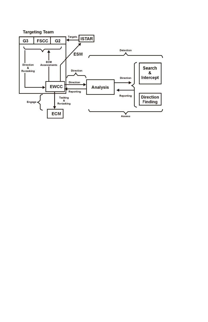
The ECM Process. The ECM process is a sub-process of the
targeting process. The EWCC receives ECM tasks through the attack
guidance matrix (AGM), which is developed by the targeting team and
approved by the commander. This process also provides additional
ESM collection tasks that the EWCC must direct to the EW system.
The ESM provides the detection (target acquisition) system for ECM.
The ESM system must provide detailed information to allow ECM to
be effective. The results of detection are provided to the EWCC to
allow for the integration of ECM into the fire support plan. The G3,
through the fire support coordination centre (FSCC), then authorizes
ECM. The EWCC then tasks ECM elements to conducts attacks. The
ESM then monitors and provides an assessment of ECM effectiveness
to the EWCC. This ECM assessment is provided to the targeting team
who start the process again.
B-GL-358-001/FP-001
47
Electronic Warfare
Figure 4-3: ECM process
20.
The conduct of ECM will have a direct effect on the ESM
collection. The ESM resources normally dedicated to ESM tasks will
be required to monitor the effects of ECM and will thus cause some
degradation of the ESM effort. Normally, many of the ECM targets
have been well developed and, therefore, the ESM effort will not be
completely degraded to support ECM. Electronic warfare support
measures should continue during ECM activities. If necessary, the G3
ISTAR will make the decision on the priority of effort based on advice
from the EWCC and the G2.
48
B-GL-358-001/FP-001
Electronic Warfare
CHAPTER 5
ELECTRONIC WARFARE SUPPORT MEASURES
SECTION 1
GENERAL
1.
Essentially electronic warfare support measures (ESM) are
the exploitation of adversary transmissions for the purpose of
providing immediate threat warning, signals intelligence (SIGINT)
about the area of interest and targeting information for electronic
countermeasures (ECM). Electronic warfare support measures are
composed of search and intercept, direction finding (DF) and analysis
functions applied against communication and non-communication
targets. The ESM process is described in chapter 4 and mirrors the
intelligence cycle. Electronic warfare support measures can be carried
out from ground-based equipment in the forward area and at greatly
extended ranges from airborne platforms. All electromagnetic (EM)
radiation has a distinct characteristic or signature, ranging from a
single radio frequency to the unique signature of an air defence
radar/weapon system. Electronic warfare (EW) units deploy
electronic sensors so they can listen to, locate and identify adversary
transmissions.
2.
Electronic warfare support measures (except for organic
communications systems) employ passive sensing. In general, ESM
can collect information throughout a commander’s area of interest and
they are an all weather capability. Ranges and accuracy (DF) of ESM
are greatly increased with the use of elevated platforms. It is unlikely
that the land forces would obtain dedicated platforms such as
helicopters and unmanned aerial vehicles (UAVs) dedicated to EW
use. However, ESM equipment needs to be modular and compatible
to allow for deployment in these platforms. Electronic warfare
support measures require special equipment, well trained soldiers and
clear direction from the intelligence, surveillance, target acquisition
and reconnaissance (ISTAR) process on priorities, the types of targets
sought and the kind of information desired so wasted effort is
prevented.
3.
To exploit the adversary's transmissions, EW elements search
the spectrum to find which frequencies the adversary is using. When
they find a target frequency, or set of frequencies in the case of
frequency agile systems, they then intercept the transmissions, use DF
equipment to locate the transmitters and then analyse the message
B-GL-358-001/FP-001
49
Electronic Warfare
content or emission types to gain information and disseminate the
information to anyone who requires it.
SECTION 2
SEARCH AND INTERCEPT FUNCTION
4.
Search and intercept should be considered electronic
reconnaissance and electronic surveillance. In general these two
functions cannot be separated as the same equipment and operators do
both functions. In the past, search was viewed as the start of the EW
process, however, it is unlikely that deployed land forces will arrive in
a theatre without some national SIGINT database support allowing for
immediate commencement of intercept tasks.
5.
Search. The search function based on SIGINT already
available conducts a reconnaissance of the EM spectrum for
exploitable activity. Search must be conducted continuously, and
some resources will always need to be dedicated to it. Analysis of the
results of the search function is very useful in determining adversary
activity even if the internal information of the communications cannot
be immediately exploited.
6.
In the early stages of an operation, search operations are vital
to providing the information necessary for development of the overall
ESM capability. The results of search provide detailed information on
the portions of the EM spectrum employed by an adversary and from
this allow the ESM package to be task-tailored to exploit the particular
theatre. This is particularly important in operations other than war
(OOTW), where the size of the EW force will be limited by the overall
contingent size.
7.
Search operators are required to exploit as much of the EM
spectrum as possible. This will include HF, VHF, UHF, SHF and
EHF bands for communications and radar activity. The general search
operator, who has some knowledge of the target language, records all
voice transmissions heard. The operator notes the frequency, the type
of modulation and the mode of transmission. If the net is operating in
plain language, the operator can log the call signs, the type of net and
an outline of the traffic. If the operator recognizes it as an important
net, the operator calls for another operator to look specifically at that
particular frequency. In the case of non-communication transmissions,
general search operators are looking for emissions with unique signal
characteristics before conducting follow on direction finding and
analysis.
50
B-GL-358-001/FP-001
Electronic Warfare Support Measures
8.
The operator involved in a specific search carries out the task
in the same way as the general search operator. The operator will be
assigned to specific frequencies and looks for specified nets.
Following a frequency change, the operator will be busy trying to
rediscover the net on its new frequency. Details of priority nets and
those which show promise of providing useful information are then
passed to an intercept operator. Modern search equipment
incorporates microprocessors, which can be programmed to
automatically scan a portion of the band, ignoring friendly or restricted
frequencies.
9.
Intercept. While the search function conducts a
reconnaissance of the EM spectrum, the intercept function conducts
surveillance of specific target frequencies. The aim of intercept is to
exploit the specifics of adversary transmissions, primarily by
transcribing unencrypted voice transmissions, facsimile and data.
These activities require very specialized operator skills such as
linguistics. Once an important radio net is identified by search, it is
handed off to an intercept operator who records the information passed
on that net. The intercept operator exploits the information on the net
to the extent possible and then passes the results to analysts for further
exploitation, fusion and reporting. The intercept operator passes the
tapes and log to the analyst in the form of data files. The same process
is conducted with regard to intercept of non-communication emitters.
10.
Many signals will not be immediately exploitable. These
signals will be recorded, logged, databases updated and passed to other
EW assets for exploitation. In certain instances, the support of
coalition national agencies will be necessary to exploit these signals.
The process of exploitation in this case must be as fast as possible to
ensure the commander is supported with timely strategic SIGINT.
However, when an immediate threat is identified, a warning in the
form of a tactical report (TACREP) is reported directly to the
electronic warfare coordination cell (EWCC) / all-source cell (ASC)
for furtherance to the targeted unit.
11.
Intercept can be conducted against secure and insecure nets,
but the information obtained will vary. Secure targets yield valuable
information in the form of emission characteristics (e.g., frequency
and modulation), and some inference can be drawn about the relative
importance of the net based on traffic patterns and location of stations.
Secure stations are still subject to DF, as are stations working insecure.
12.
From intercept the analysts receive information about
frequency, message content, traffic flow, activity patterns and
B-GL-358-001/FP-001
51
Electronic Warfare
transmission types. This information is enhanced by locations and
movement provided by DF. In conjunction with other sources of
intelligence, the analyst will try to determine the adversary order of
battle, strengths, intentions, unit identities and deployment.
13.
Search and Intercept Equipment. The fundamental
equipment in any search and intercept system is the receiver and
associated antenna. Intercept receivers are very sensitive with a high
degree of frequency accuracy and stability. With a high gain antenna
and good siting, receivers are capable of exploiting signals at a greater
range than normal communication receivers. Intercept receivers
usually incorporate a digital frequency meter, which gives the operator
a precise frequency read-out for use by direction-finding stations.
They also have a panoramic display that can detect all transmissions
within a certain range even if these transmissions are infrequent or
short.
SECTION 3
DIRECTION FINDING
14.
Direction finding is an ESM function that provides location
information on target emitters. This information when fused with
other search and intercept information is invaluable. Direction-finding
equipment is a receiver with a specialized antenna system that is
capable of providing a line of bearing (LOB) to where the emitter is
located. The quality of the DF system, terrain, signal strength and
reflection determines the accuracy of the LOB. The accuracy of
current systems is in the range of one to three degrees. Current
systems determine the location of an emitter by triangulation. Three
or more direction-finding stations are used along a baseline, each
taking a LOB on the target station transmission simultaneously. At a
regular operating range of a DF baseline—15 km or 20 km—this
equates to an accuracy or circular error probability (CEP) of
approximately 1000 m. It is for this reason that DF alone cannot yet
be regarded as a target acquisition system for fire support. However,
ESM data including DF provides excellent cueing for other sensors to
detect targets with sufficient accuracy to target. Increasing the number
of bearings obtained and using elevated DF platforms can improve DF
accuracy. Additionally, DF accuracy tends to improve when targeting
higher frequencies. As technology advances, we can expect in the
future that locating emitters will improve significantly. Current
electronic intelligence (ELINT) DF systems have an accuracy of 1/10th
of a degree. It is expected that this will provide targets within 100 m
at ranges of up to 20 km.
52
B-GL-358-001/FP-001
Electronic Warfare Support Measures
15.
Emitter Density Location. A number of secure and insecure
transmissions on different frequencies all emanating from the same
area may indicate the location of an important headquarters. In any
formation, each type of unit or level of headquarters will have its own
distinctive electronic signature, which, if identified and located, will
obviously provide vital intelligence. The interrelationship between
stations on a net and their locations is an important element in
establishing the adversary's electronic order of battle.
16.
In the near future it can be expected that search, intercept and
DF functions will be conducted from the same platform. Integration
of intercept and DF information will thus be greatly improved, and a
large analytical effort to fuse this information will be reduced. This
will result in combined ESM detachments for search, intercept and
DF. Current ELINT systems already have an integrated search,
intercept and DF capability.
17.
In the HF frequency band, “single station location” can be
done. In effect the target emitter is located by a single ground station
and not by triangulation with a deployed baseline. Again, it is
expected that in the near future, this type of locating capability will be
available in other bands a well. In essence, the need to deploy a
baseline to obtain accurate DF information will be reduced. This will
have particular application in OOTW, where a limited number of EW
systems can be deployed, and in situations where it is not practical to
deploy baselines.
18.
Ground-based detachments must be located in forward areas
and sited to obtain a good electronic view of the adversary emitters
(usually line of sight). As with search and intercept equipment, DF
equipment benefits from elevated platforms via UAV and aviation
assets. This greatly improves the accuracy and range over
ground-mounted systems but is limited by the availability of platforms
and weather. Direction finding via elevated platforms should augment
a ground-based capability.
SECTION 4
ANALYSIS
19.
Analysis is a process of taking sensor data and converting it
into information that is useful. It is important to understand that
analysis occurs throughout the ESM process and not just as a final
step. The key principles in analysis that apply to ESM are accuracy
and speed. The outputs from analysis are SIGINT, immediate threat
B-GL-358-001/FP-001
53
Electronic Warfare
warnings, ECM targets and assessments of the effectiveness of ECM
and other IO measures such as PSYOPS or deception.
20.
Specially trained SIGINT analysts primarily carry out the
analysis function. The analyst takes direction (priority intelligence
requirement) from the EWCC and converts this into tasks for the ESM
sensors. The ESM sensors then collect the necessary data and
information and provide them to the analysts. The analysts then take
the sensor results, use various databases and produce their products.
The analyst must integrate information from search, intercept, and DF
of communication and non-communication emitters and produce a
SIGINT view of the battle. From an all-source cell perspective,
SIGINT is considered a “single source” that must be integrated with
other sensor information (recce, UAV, HUMINT) to produce Red
situational awareness (SA) for the commander.
21.
Accuracy of the products is critical. The ESM process must
produce reliable information and be able to indicate to the ASC how
accurate the information is. Inaccurate information can have a
detrimental effect on the entire process of producing Red SA. Speed
of reporting requires the ESM process to produce accurate results as
quickly as possible. This allows the commander to have Red SA
faster and hence enables him to quicken his decision-action cycle
relative to the adversary’s.
22.
With software and databases being part of ESM systems,
software can compare ESM results to known databases and provide
instantaneous analysis of a signal. This is particularly true in ELINT.
Radars are detected, characterized, located, identified and reported
without necessarily having a human interface. This level of analysis
converts signal data into useful information. Search and intercept
operators conduct analysis based on knowledge of the adversary
systems. In principle, the analysis should be done as quickly as
possible using integral software and operator knowledge. As analysis
and data fusion software develops, ESM equipment and operators will
conduct more analysis. Analysis is a time consuming process. The
adversary uses many means to ensure that it takes considerable time to
produce results.
23.
From intercept, the analysts receive information about
frequencies, call signs, types of net, message content, traffic flow,
activity patterns and transmission types. For both radio and radar,
intercept can identify the equipment by its technical characteristics
(electronic fingerprinting). When fused with locations and tracks from
DF, this information enables the EW analyst to build up the adversary
54
B-GL-358-001/FP-001
Electronic Warfare Support Measures
electronic order of battle. The result of their efforts will be
intelligence concerning the adversary order of battle, strengths,
intentions, unit identities and equipment developments. Some
information cannot be held by the analyst while developing SIGINT
since it is time perishable and therefore must be passed immediately to
the EWCC/ASC for action. The analyst is a detective and quickly
seizes upon any errors or breaches of security. The building up of an
overall SIGINT picture by analysis is a lengthy process. If the
adversary EPM is effective, SIGINT obtained by intercept is
fragmentary at first and gains coherence only as a result of close
observation over a period of time.
24.
Location of Analysis. Many factors dictate the location of
the analysts. Factors that would determine the location of the analysis
function are:
a.
Continuity. ESM analysis needs to be continuous.
When there is a period of time that analysis is not
being conducted, gaps in knowledge are created that
will directly affect the accuracy and speed of
reporting. The analysis function needs to be as
stationary as possible, have redundant capabilities or
a split based capability.
b.
Access to Databases. The analysis function
requires access to databases both for SIGINT and
other intelligence information. The databases
provide quick references to previously conducted
activities and greatly speed the analysis process.
c.
Communications. Limitations in the size of
communications links may require analysts to
deploy directly with the sensors. In other cases, the
communication may allow for the analyst to be
physically separated from the sensors but in virtual
contact. The analysis function must have reliable
communication with the ESM sensors. The
commander must always have some analysis
capability in theatre to allow for time of
communications disruptions.
25.
Traditionally the analysis function has been co-located with
the search and intercept functions. Tactical communications has
normally been conducted with low bandwidth tactical radios. The
analyst had to reduce the amount of information passed to a size that
B-GL-358-001/FP-001
55
Electronic Warfare
could be routinely transmitted by that means. The arrangement also
allowed for a close relationship between intercept and analysis.
Current communications technology will soon allow a far more
flexible deployment of the analysis function. In recent operations,
both sensor and analysis functions have been conducted in separate
locations over strategic distances. Additionally, the analysis function
has been integrated with ESM sensors into a single vehicle detachment
on occasion. This demonstrates that the location of the analysis
function is flexible and mission dependant.
26.
Within the ISTAR CC there will likely be a need to have
SIGINT analysis capabilities. This will create a synergy with the ASC
and the other sensors. As well, national level communications links
will be readily available to the analysts.
27.
Analysis Security. Many SIGINT databases and analytical
methods are highly classified and specially protected. This creates a
requirement for a special compartmented information facility (SCIF).
Access to the information and many SIGINT products require special
security clearances. Commanders, designated staff and the ISTAR CC
will require regular access to this information and will need to be
cleared appropriately.
28.
Dissemination of Analysis Products. Analysis derived
products will be disseminated on a need to know basis. In general, the
products will be sanitized to allow them to be passed on the Land
Force command and control information system (C2IS) systems. The
sanitation procedure will be in accordance with nationally set
guidelines and the source protection necessary. The normal products
of the EW process are:
a.
Tactical Reports and Summaries. These reports
are produced in an approved text format that allows
for quick dissemination, database updates and
display on maps as necessary.
b.
Overlays. Overlays allow for a pictorial
representation of various ESM results. For example,
all air defence radars, and all or selected DF results.
29.
Enemy Electronic Deception verses Analysis. Analysts
must be aware that an adversary may attempt deception. A properly
conceived deception plan is aimed at the commander not the ESM
system. An electronic deception is normally planned as part of an
overall deception plan. In some instances, however, it is possible for
only an electronic deception to be attempted. In this case, the aim is to
56
B-GL-358-001/FP-001
Electronic Warfare Support Measures
deceive the ESM system into reporting false information that will be
reported to our commander. Analysts must be aware that deception is
possible and question results that appear unusual. When this occurs,
the ISTAR system may be able to confirm or deny the adversaries use
of deception with other sensors. Analysts should not be over cautious
and not report for fear of deception.
30.
Conclusion. As discussed before, automated tools will
significantly speed up the analysis process. Analysts must still be
highly skilled in order to quickly make sense of a myriad of data.
Although progress in the areas of artificial intelligence and automated
tools is constantly being made, the main tool remains a highly skilled
analyst.
SECTION 5
ELECTRONIC INTELLIGENCE ELECTRONIC WARFARE
SUPPORT MEASURES
31.
ELINT ESM. The previous paragraphs describe the ESM
process—consisting of intercept, search, DF and analysis—and the
application of these sub-processes against communication-based
emitters. It should be re-emphasized that the same ESM process is
applied against non communication-based emitters and results in an
ELINT product. Each radar has a characteristic frequency, power,
pulse length, pulse repetition frequency, beam width, antenna scan rate
and polarization. These properties determine the function and
operating parameters of radar and may be used to classify and identify
it. The characteristics are compared to a database, and the specific
radar can be identified. ELINT systems require a large database of
previously collected signals to be most effective. The database must
be theatre specific.
32.
LISS Support to ELINT ESM. Land integrated support
station (LISS) provides the necessary databases for ELINT systems.
The databases are built from the CF EW Database (CFEWDB). New
ELINT signals are normally beyond the deployed EW system to
exploit. The ELINT system provides the characteristics of the emitter
to the LISS, which, in coordination with other agencies, identifies the
emitter and updates the database. Therefore, new databases are
required constantly to ensure ELINT systems identify signals
correctly. Most radars may be associated with a particular gun or
missile fire control system or a missile guidance/homing system. In
these cases, analysis of the interception usually reveals the state of
activation of the whole weapon system and the type of system the
B-GL-358-001/FP-001
57

Electronic Warfare
radar is associated with. Fig 5-1 is illustrative of the how the LISS is
situated to support Land Force EW ops.
Figure 5-1: EW Operational Support
58
B-GL-358-001/FP-001
Electronic Warfare
CHAPTER 6
ELECTRONIC COUNTERMEASURES
SECTION 1
GENERAL
1.
Electronic countermeasures (ECM) are the offensive arm of
electronic warfare (EW). Electronic countermeasures are coordinated
through the targeting process as described in Chapter 3. The
electronic warfare support measures (ESM) process is the target
acquisition (TA) system for ECM. Electronic countermeasures are
subdivided into three categories: electronic jamming, electronic
deception and electronic neutralization.
SECTION 2
ELECTRONIC JAMMING
2.
Electronic jamming is the deliberate radiation, re-radiation or
reflection of electromagnetic (EM) energy with the object of impairing
the effectiveness of electronic devices, equipment or systems being
used by an adversary. Jamming used at the right time on the right
targets (e.g., on command links during an assault) can greatly reduce
the adversary’s effectiveness by denying him critical information and
communications. If jamming is poorly coordinated, it will alert the
adversary and can compromise our own capability and intentions. If
jamming is conducted too early, it will allow the adversary time to
react and restore communications and therefore have limited effect. A
jamming signal can affect both friend and foe, and its effects can be
widespread. Adversary transmissions are often a source of
intelligence, and if they are jammed, the information they provide is
lost. Jamming, therefore, is an activity that must be closely directed
and coordinated by the G3 staff.
3.
Within the Land Force, EW units conduct electronic
jamming. The responsibility for jamming rests with the G3/COS, and
jamming is coordinated by the FSCC and electronic warfare
coordination cell (EWCC). The EWCC is responsible for the
execution of jamming based on targets determined by the targeting
process. Coordination with other staffs, in particular the G2 and G6, is
critical.
B-GL-358-001/FP-001
59
Electronic Warfare
CONTROL OF JAMMING
4.
Jamming operations are most successful when they are
permitted the greatest possible latitude to attack both planned and
opportunity targets. Coordination of jamming operations should
commence early in the planning cycle and continue through all
operational phases. The measures for controlling jamming are
normally contained in the operations order. Control is exercised in
one of four ways:
a.
Positive Control. Positive control is the issuance of
specific orders to jam and/or deceive a given target
or blanket authority to neutralize by jamming and/or
deception a category of target (for example, an
adversary fire control net or ground surveillance
radars). Frequencies and times are not specified.
b.
Negative Control. Negative control is the denial of
permission to conduct jamming (for example, no
jamming before H-hour).
c.
On/Off Control. On/off control is the direct control
of a jamming operation from moment to moment.
d.
Restricted Frequency Control. Restricted
frequency lists (RFLs) are a mechanism to prevent
jamming from effecting friendly operations. Annex
A to this chapter provides a process and procedures
for developing and maintaining RFLs. There are
three categories of frequencies:
(1)
Taboo. A “friendly” frequency on which
jamming or other intentional interference is
prohibited.37
(2)
Guarded. An adversary frequency used as
a source of information.38
(3)
Protected. A “friendly” frequency on
which interference must be minimized.39
37 ATP 51(A) Chapter 4.
38 ATP 51(A) Chapter 4.
60
B-GL-358-001/FP-001
Electronic Counter Measures
5.
These four methods of controlling jamming are applied in a
manner that permits maximum flexibility and minimum delay in
obtaining authority to conduct jamming operations without
compromising limitations imposed by superior headquarters. Unless
forbidden by a higher commander or established rules of engagement,
any formation commander can authorize jamming. Commanders at all
levels must be fully conversant with the orders governing the use of
jamming and be aware of the possible adverse effects on intelligence
collection, command and control and weapon systems.
6.
Jamming is a technique that is used to “capture” an
adversary’s communication device (radio) by radiating enough energy
that the intended receiver only receives the jamming signal and only
the intended one. Jamming effectiveness is determined by several
factors:
a.
Jammer Power. In general, the higher the power
the more effective the jamming.
b.
Range to the target Receiver. The closer the
target, the more effective the jamming.
c.
The Link Distance. The link distance is the
distance between the transmitter and receiver. The
longer this distance, the more effective the jamming
is (less jamming power is required).
d.
Ground. For ground-based jammers, the ground
itself can mask the target or necessitate greater
power to produce effective jamming.
e.
Power of the Adversary Transmitter. Depending
on the power output of the adversary transmitter,
more jammer power may be required to effect
jamming. Normally, the power output is known and
can be factored into the equation to determine the
required jammer power output.
7.
Jammers can use a variety of modulations. It is important to
tailor the jamming modulation to the target. The most successful
jammer is one that is perceived as anything but a jammer. For
example, the jammer can use a random Morse signal against a net
39 ATP 51(A) Chapter 4.
B-GL-358-001/FP-001
61
Electronic Warfare
operating on Morse code or use a random data signal against a data
net.
8.
Types of Jamming. The types of jamming that may be
employed are as follows:
a.
Spot Jamming. Spot jamming occurs when a
jammer attacks one frequency or narrow band of
frequencies in specific use by the victim. It is
normally tuneable over a range of frequencies. Spot
jamming causes minimum interference with friendly
systems and permits maximum use of available
jamming power. A spot jammer requires very
accurate knowledge of adversary frequencies.
b.
Barrage Jamming. Barrage jamming occurs when
a jammer attacks over a wide band of frequencies
simultaneously. The power available will be spread
over the entire bandwidth; this results in less power
on any particular frequency than occurs with spot
jamming. Barrage jamming is likely to harass the
victim over a number of frequency options rather
than totally deprive the victim of using any
particular frequency. Less detailed steerage is
necessary for barrage jamming. Also, the chance of
interference with friendly nets is greater than with
spot jamming.
c.
Sweep Jamming. Sweep jamming attempts to
compromise between the advantages of spot
jamming and barrage jamming. The frequency of
the jamming signal is continuously varied within a
specific bandwidth. All available power is used for
one frequency or a narrow band at any instant, but
the tuning is swept back and forth across a whole
band of frequencies. Higher sweep rates can achieve
more effective results.
d.
Automatic Search Jamming. More sophisticated
jammers use advanced technology to maximize their
effectiveness yet reduces their vulnerability. The
automatic search jammer (also known as a
responsive jammer) incorporates an intercept
receiver, which automatically searches a selected
band of frequencies to find frequencies of interest
62
B-GL-358-001/FP-001
Electronic Counter Measures
for which the system has been programmed. The
jamming transmitter is then automatically tuned and
activated on the target frequency. For the victim
station, the jamming appears to be continuous.
Sometimes a capability is incorporated into the
system to look through the jamming transmissions
and follow any changes in frequency made by the
victim. Complex systems will include a computer
management function, which allocates power
resources to simultaneous targets.
JAMMER PLATFORMS
9.
To be effective, a ground-based jammer has to be sited close
to the FLOT (forward line of own troops) so it can take advantage of
the high power output (which is typically between 1 kW and 2 kW).
This siting allows the jammer to be effective against targets that are in
depth (for example, artillery nets), but it makes the jammer vulnerable.
Thus the jammer should be mounted in an armoured vehicle.
Mounting the jammer on an elevated platform such as an UAV can
eliminate the loss of power of a jamming signal caused by intervening
terrain (attenuation). This technique provides a line of sight path from
the jammer to the target receiver, thus enabling a lower power jammer
to be used. An airborne jammer of as little as 200 watts output at a
distance of 40 km can be as effective as a ground-based jammer of
2 kW output at 15 km.
EXPENDABLE JAMMERS
10.
Expendable jamming involves placing a low power jammer
within a few hundred metres of a target receiver. This can have the
same disruptive effect as a high power jammer 15 to 20 km away.
Expendable jammers can be hand-placed, airdropped or artillery
delivered. They can be programmed to lock on to strong local signals,
or they can be programmed to switch on to a certain frequency at a
predetermined time. If expendable jammers are delivered as a mix
with explosive ordnance, they could seriously degrade the adversary's
efforts to restore order out of chaos. Special forces, reconnaissance
and forward troops may be tasked to place expendable jammers. Their
use would be coordinated, as with other jamming, through the
targeting process.
B-GL-358-001/FP-001
63
Electronic Warfare
ELECTRONIC COUNTERMEASURES AS ELECTRONIC
PROTECTIVE MEASURES:
JAMMING IN NON-ELECTRONIC WARFARE UNITS
11.
Systems are now available that can provide protection for
Land Forces by using jammers against electronic artillery fuses such
as variable-time or proximity fuses. The jammer causes the artillery
round to detonate prematurely. The system detects the signal from the
artillery round and automatically sends a signal, which detonates the
round. The system is, in fact, a combination of ESM and ECM that
provides electronic protective measures (EPM).
SECTION 3
ELECTRONIC DECEPTION
“All warfare is based on deception.”
-Sun Tzu, The Art of War, c. 500 BC, tr. Griffith.
12.
Electronic deception (ED) is the deliberate radiation, re-
radiation, alteration, absorption or reflection of EM energy in a
manner intended to confuse, distract or seduce an adversary or his
electronic systems. Electronic deception is a component of the
commander’s overall deception plan,40 which, in turn, is part of the
commander’s overall information operation plan.
13.
The aim of deception is to mislead the adversary commander
and induce him into doing something counter to his interests. The EM
spectrum is an ideal medium to employ deceptive techniques because
it is shared with the adversary. His ESM system is a means to provide
him false information. Electronic deception is employed as part of an
overall tactical deception plan and cannot be practiced
indiscriminately. Careful scripting and control at the highest possible
level are required as well as highly skilled operators who must be well
briefed. On the other hand, low-level imitative deception can be
attempted by EW elements if the aim is limited to delaying adversary
traffic from a few minutes to a few hours or if there is an opportunity
to temporarily confuse adversary commanders at formation or unit
level. Electronic deception is a potent weapon with few of the
disadvantages of jamming, but it can be very expensive in manpower
and equipment.
40 More information on deception can be found in B-GL-352-001/FP 000
Land Force Deception.
64
B-GL-358-001/FP-001
Electronic Counter Measures
14.
Electronic deception must be considered during the planning
phase of any deception plan. The G3 has responsibility for developing
the overall deception plan. The planning of ED is the responsibility of
the EWCC on behalf of the G3 (via a designated G3 IO). Many other
staffs are involved with the development of deception plans. Annex B
to this chapter provides a guide for the EWCC to plan and coordinate
ED. Electronic deception is particularly effective in the following
circumstances:
a.
When the adversary relies heavily on a
communications and information systems (CIS)
using the EM spectrum. Electronic deception may
cause the adversary—by the manipulation, distortion
or falsification of electronic transmissions—to react
in a manner prejudicial to his interests.
b.
When the adversary ISTAR system is dependent on
the ESM (tactical and national level).
c.
When it is skilfully conducted and fully integrated
into the overall deception plan.
d.
At a critical time in the adversary’s operations.
15.
Electronic deception is divided into three categories:
a.
Manipulative Electronic Deception. This type of
ED puts out false information over our own emitters
so it can be intercepted by the adversary and treated
as real information (for example, dummy radio
traffic).
b.
Simulative Electronic Deception. This type of ED
is the creation of electronic signatures (for example,
false radio net).
c.
Imitative Electronic Deception. This type of ED
emits signals designed to convince the adversary
these signals belong to the adversary (for example,
intruding on an adversary net).
16.
All units in a formation could be involved in ED. Electronic
warfare units can provide imitative ED but little more.
B-GL-358-001/FP-001
65
Electronic Warfare
SECTION 4
ELECTRONIC NEUTRALIZATION
17.
Electronic neutralization (EN) is the deliberate use of EM
energy to either temporarily or permanently damage adversary devices
that rely exclusively on the EM spectrum. Electronic neutralization is
usually brought about as a result of a directed energy (DE) or particle
beam (PB) weapon depositing sufficient EM energy on a target so as
to render useless the target, its electronics or both. The use of lasers to
destroy sensitive optical viewing devices is one such example.
Electronic neutralization is characterized by the requirement for line of
sight (LOS) and the near instantaneous time of flight (approaching or
at the speed of light).
18.
Electronic neutralization carries with it a risk to our own
troops. As a consequence, great care and safety must be used when
employing certain types of DE weapons. Directed energy weapons
will have applications in close combat, LOS engagements. The
doctrine for employing these weapons will be contained in the
manuals of those arms that employ the weapons. EW units are not
involved directly with EN. Land EW operational support (LEWOS)
may be involved in the reprogramming of systems to detect the use of
EN.
66
B-GL-358-001/FP-001
Electronic Warfare
ANNEX A
RESTRICTED FREQUENCY LISTS
INTRODUCTION
1.
The purpose of this annex is to outline procedures for
producing and maintaining restricted frequency lists (RFLs). An RFL
is defined as a list of taboo, guarded and protected frequency lists.
The terms taboo, guarded and protected are defined as follows:
a.
TABOO. A “friendly” frequency on which
jamming or other intentional interference is
prohibited.
b.
GUARDED. An enemy frequency used as a source
of information.
c.
PROTECTED. A “friendly” frequency on which
interference must be minimized.
2.
The G3 staff is responsible for the compilation, maintenance
and distribution of the RFL, however, the EWCC will provide the staff
effort to assist.
3.
This annex is organized as follows:
a.
RFL production and dissemination;
b.
RFL maintenance procedures; and
c.
RFL format.
SECTION 2
RFL PRODUCTION AND DISSEMINATION
4.
The formation structure and associated CIS must be known in
order to produce a standard RFL. The procedure for the production of
the RFL is as follows:
a.
Produce standard formation taboo and protected list;
b.
produce guarded list;
c.
G6 staff input frequencies to taboo and protected
list;
d.
G3 (EWCC) compile list; and
e.
G3 issues RFL.
B-GL-358-001/FP-001
67
Electronic Warfare
STANDARD FORMATION TABOO AND PROTECTED LIST
5.
The purpose of this list is to produce a standard (SOP) list of
activities (for example, AD, surveillance nets, etc) that are to be given
the status of taboo and protected. These lists will facilitate the quick
production of the RFL, which could readily change. Each formation,
from brigade to corps, must undertake this process.
6.
To produce the taboo and protected lists, the following
agencies will need input:
a.
G6 staff;
b.
EWCC;
c.
G2 staff;
d.
G4 staff;
e.
Arty, Avn, Engr staffs; and
f.
subordinate formations.
7.
G3 staff would then approve the taboo and protected lists.
Once this process has been completed, the G6 staff can routinely add
frequencies to the approved lists. G2 staff, with input from EWCC,
produces the guarded frequency list. The G3 staff, with assistance
from the EWCC and with the superior formation’s RFL, produces the
RFL. G3 then approves the list and disseminates to subordinate
formations and EW units. Figure A-1 depicts this process.
Figure 6A-1: The RFL Process
68
B-GL-358-001/FP-001
Annex A to Chapter 6
RFL MAINTENANCE PROCEDURES
8.
Maintenance of the RFL is critical. The RFL shall be
updated at the following times:
a.
When a new operation order is being prepared. This
will require a complete review of taboo and
protected lists.
b.
Routinely updated every 24 hours (or as necessary to
conform to CEOI changes).
c.
Attachments and detachments from the formation.
d.
Periodic updating as minor changes occur (for
example, single taboo frequency change or updates
to guarded frequencies).
9.
Subordinate formations, the G6 staff and the G2 staff are
responsible to advise the G3 staff when changes to the RFL are
required. The EWCC will ensure that EW units are immediately
advised of any change to the RFL.
RFL FORMAT
10.
The format and an example of an RFL are contained in
Appendix 1.
B-GL-358-001/FP-001
69

Electronic Warfare
APPENDIX 1 TO ANNEX A
RFL FORMAT AND EXAMPLE
**SECURITY CLASSIFICATION**
RESTRICTED FREQUENCY LIST—FORMATION
EFFECTIVE DATE AND TIME
TABOO
FREQUENCY
USE
TIME
1
2
GUARDED
FREQUENCY
USE
TIME
1
2
PROTECTED
FREQUENCY
USE
TIME
1
2
**SECURITY CLASSIFICATION**
NOTES
TIME—Normally the RFL will have an effective date and
time. In some cases a particular frequency may have an
abbreviated time period and this will be noted in column 4.
B-GL-358-001/FP-001
71
Electronic Warfare
EXAMPLE RFL
**SECURITY CLASSIFICATION**
RESTRICTED FREQUENCY LIST—1 DIV
EFFECTIVE 120001Z TO 120001Z DEC 95
11.
TABOO
a.
1
47.50 MHz—Div Comd
b.
2
71.05—Div Arty Command
c.
3
30.50—1 Bde Comd—1300-1500hrs
12.
GUARDED
a.
1
2030 KHz
b.
2
53.45 MHz
c.
3
223.5 MHz
13.
PROTECTED
a.
1
30.50 MHz—1 Bde Comd
b.
2
3550 KHz—Div Comd Guard
c.
3
345.5 MHz—Div Radio Relay
**SECURITY CLASSIFICATION**
72
B-GL-358-001/FP-001
Electronic Warfare
ANNEX B
ELECTRONIC DECEPTION
INTRODUCTION
1.
The purpose of this annex is to provide guidance for planning
and coordinating electronic deception (ED). Electronic deception is
“the deliberate radiation, re-radiation, alteration, absorption or
reflection of electromagnetic energy in a manner intended to confuse,
distract or seduce an enemy or his electronic systems.” Electronic
deception is but one component of an overall deception plan that will
be an integral part of the information operations (IO) plan.
2.
Electronic deception is normally conducted as a part of a
commander's deception plan and must be full planned and coordinated
with it. The G3 staff has general responsibilities for planning and
coordination of the commander’s deception plan. The EWCC is
responsible through the G3 for the planning and coordination of the
ED plan in support of the overall deception plan.
3.
This annex concentrates on the EWCC activities necessary to
plan and coordinate ED. A checklist is provided at Appendix 1 to
assist EWCC staffs in planning ED. The organization of this annex is
as follows:
a.
ED planning; and
b.
EWCC checklist for ED.
ED PLANNING
4.
The deception plan has its beginning in the commander’s
concept of operations in which he identifies the need for a coordinated
deception plan in order to successfully conduct his operation. The G3
staff, specifically a designated G3 IO, must then plan the deception in
conjunction with all staff branches. The EWCC, G2 and G6 staffs will
provide the advice necessary in conducting an ED as part of the
overall deception plan. In some cases, the commander’s entire
deception plan may be based on an electronic deception depending on
the enemy's intelligence gathering capabilities.
5.
From an EW point of view, two aspects are critical to
successful conduct of ED:
B-GL-358-001/FP-001
73
Electronic Warfare
a.
Comprehensive Database. A comprehensive
database is essential to the development of ED plan
in order to determine what aspects of an adversary
can be deceived. The database will provide the
necessary information on which adversary systems
are dependent on the electromagnetic spectrum and
therefore can be deceived.
b.
ESM. Electronic warfare support measures (ESM)
are critical in monitoring the success of any
deception plan. ESM will likely be the first
indicator of the success or failure of the overall
deception plan and will provide what the adversary’s
reaction to our deception is. Electronic warfare
support measures provide critical input into the
overall database and will directly influence the ED
plan.
6.
The electronic deception plan will need to create a misleading
picture to the enemy tactical ESM and national signal intelligence
systems to the point that their reports to the appropriate commander
cause him to react (or not react) in a way favourable to our
commander’s aim. As a result, a realistic emitter picture must be
“painted.” This will require significant planning and coordination to
execute and will likely require emitters from various elements not just
signal and EW elements.
7.
The commander must set out the aim of the deception plan.
The G3 IO staff then work on options for the deception plan. The
EWCC will be required to do an estimate to produce options for an
electronic deception plan to support the commander’s deception plan.
The result of this estimate will be an annex (or possibly a separate
operation order) to the deception plan operation order.
8.
In order to conduct the estimate, the EWCC will need to
coordinate with the following:
a.
G3 IO;
b.
G2 Staff;
c.
G6 staff;
d.
higher and lower EWCCs; and
e.
other arms (provision of resources).
74
B-GL-358-001/FP-001

Annex B to Chapter 6
9.
It is likely that the most significant factor will be the
availability of resources (emitters) to conduct the plan. The significant
use of equipment could jeopardize the CIS and surveillance plans.
Every effort must be made to keep the resources to the minimum
necessary to successfully conduct the electronic deception.
10.
The result of the estimate will produce a plan and the critical
contents of the ED annex to the deception plan. The annex will
contain the tasks and coordination necessary to conduct the ED.
Appendix 1 contains a checklist guide to contents of the ED annex.
11.
The ED annex will provide the detailed coordination
necessary to execute the plan. After the issue of appropriate orders,
the EWCC will need to monitor and coordinate changes necessary.
Electronic warfare support measures assets will need to be tasked to
monitor the enemy's reaction to the deception to confirm the success
of the deception. EWCC is responsible to advise the G3 IO of the
results.
Figure 6B-1: The ED Process
B-GL-358-001/FP-001
75

Electronic Warfare
APPENDIX 1 TO ANNEX B
ED PLANNING CHECKLIST
G3/G3 IO
Commanders IO/deception concept of ops
Timings
Resources available
Additional resources from higher
G2
Adversary surveillance capability
Confirming results
ESM (tactical, coalition, strategic) capabilities required to
monitor deception
Comprehensive database
G6
Resources available
Special CEOI required
Nets required
Spectral use
G4/Other Arms
Resources available
Nets for simulation
EW
ESM tasks
Monitor deception
Database input/updates
ECM TASKS
Subordinate Formations
Execute tasks
Provide resources
B-GL-358-001/FP-001
77
Electronic Warfare
CHAPTER 7
ELECTRONIC PROTECTIVE MEASURES
SECTION 1
GENERAL
1.
An often neglected, but most important division of electronic
warfare (EW), is electronic protective measures (EPM). These are the
defensive EW measures that all units must practice and use.
Electronic protective measures are an all-arms responsibility.
Electronic protective measures features included in the design of
command and control information system (C2IS) equipment and
weapon systems must be combined with EPM procedures and tactics
to reduce the effect of the adversary’s electronic warfare support
measures (ESM) and electronic countermeasures (ECM) effort.
Commanders are responsible for assessing the potential vulnerabilities
of their electronic equipment, uncovering weaknesses that may be
exploited by hostile EW activities, and developing appropriate
defensive EW procedures. Electronic protective measures tactics must
be considered in light of the tactical situation and must be included in
commander’s operations plans to preclude reacting hastily during the
heat of battle.
2.
To develop a sound EPM, commanders and staff at all levels
must:
a.
Acknowledge the extent of our own military reliance
upon electronic systems and the vulnerability of
those systems to ESM and ECM.
b.
Understand that the adversary has the capability to
exploit and disrupt all our electronic systems. This
capability, if exploited to its full extent, will give the
adversary a significant tactical advantage.
c.
Take steps to ensure the adversary does not gain
such a military advantage by protecting our
electronic systems through well-practiced EPM
procedures and tactics.
3.
The aim of EPM is to defeat the adversary’s ESM and
national signal intelligence systems and his ECM. It is important to
remember that defence against EW attack applies both in peacetime
and in war. It must be assumed that the potential adversary is always
listening and intercepting even though the he may reserve jamming
and deception for war. The ability to survive an electronic attack
B-GL-358-001/FP-001
79

Electronic Warfare
depends on our knowledge of the adversary’s capability and our
standard of EW training. Electronic protective measures take the form
of a two-phased defence: defeat ESM and defeat ECM.
4.
Some measures are both anti-ESM and anti-ECM in their
effect. It is significant that ECM relies heavily upon effective ESM
steerage. Therefore, most of the EPM which effectively deny the
adversary an opportunity to conduct ESM prevent or reduce his ECM
at the same time. Therefore, the first phase of EPM is anti-ESM.
SECTION 2
SUB-DIVISIONS OF ELECTRONIC PROTECTIVE
MEASURES
5.
Electronic protective measures can be technical, procedural
or tactical as illustrated in Figure 7-1. The consolidated result of
effective EPM is a good signals security (SIGSEC) posture, which is
an important part in our overall operational security. To achieve an
acceptable level of SIGSEC, the most important ingredient is realistic
operator training that will enable the operator to continue to function
in a hostile EW environment.
Figure 7-1: Electronic Counter-Countermeasures
SECTION 3
TECHNICAL MEASURES
6.
Design. Electronic protective measures are becoming
increasingly important in the technical design of all radio and radar
equipment. New transmission, encryption and antenna techniques are
80
B-GL-358-001/FP-001
Electronic Protective Measures
being developed to reduce electronic visibility, deny the adversary
information or enable the operator to work through an electronic
attack. Even the current generation of electronic equipment has some
built-in EPM features. Most combat radios have variable power that
can be kept low to avoid detection or can be increased to work through
jamming. The gain control, which adjusts brilliance and contrast on a
radar screen, may sufficiently remove the effects of chaff to reveal the
wanted target.
7.
Frequency Diversity. The development of our entire family
of tactical radios also reflects a form of EPM by providing diversity
across all frequency bands. For example, HF (AM) is usually used for
guard communications to back up VHF (FM) radio. Similarly, UHF
radio and radio relay, with their better line of sight characteristics, are
used for other command and control links.
8.
On-Line Encryption. This method will deny the adversary
knowledge of the content of message traffic; however, the presence of
a signal can still be detected, enabling the adversary to conduct
direction finding. On-line encryption devices are used on most tactical
radio circuits including voice, teletype, data and facsimile. The
advanced generations of equipment enable the net control station to
electronically key or exclude stations (if required).
9.
Off-Line Encryption. This method, including machine and
non-machine ciphers, can give protection to message content equal to
that of on-line encryption. A variety of other lower level codes and
devices can give limited protection to all or selected parts of messages.
Technology has reached the point where traditional paper codes will
be replaced or supplemented by a hand held calculator-type device,
which can provide immediate encryption and decryption.
10.
Directional Antennae. A more specialized method of
achieving minimum power in the adversary's direction is by using
directional antennae (see Figure 7-2 (a)). These are usually used for
VHF and UHF radio relay systems, but can also be used for point-to-
point HF and VHF radio links. Directional antennae can be used on
long rebroadcast nets whereby the rebroadcast station splits and works
to the forward units on low power and works rearward using a
directional antenna on high power. Ideally, circuits using directional
antennae should be oriented parallel to the forward edge of the battle
area (FEBA) to reduce the radiation in the adversary's direction. Side
and back lobes are still subject to adversary intercept but to a lesser
degree.
B-GL-358-001/FP-001
81
Electronic Warfare
11.
Steerable Null Antennae. Figure 7-2 (b) shows the polar
diagram of a vertical omni directional antenna or standard whip
antenna. Research is being carried out on steerable null antennae
(Figure 7-2 (c)), which will radiate normally in all directions.
However, efficiency will be greatly reduced in the direction of the
adversary antenna. As the antenna will have the same properties for
both transmission and reception, radiation to or from the adversary is
minimized; this will reduce the likelihood of intercept and will reduce
the effect of jamming. A processor that is connected drives steerable
null antennae to the radio inside the vehicle.
12.
Burst Transmission. Digital message devices are now being
developed that enable short formatted messages to be entered into a
small memory then transmitted in a short burst. These devices can be
used over most normal voice radios and obviously reduce transmission
time for lengthy messages. Typical applications for these devices are
on fire control and administrative nets and by special forces inserted
into adversary territory.
Figure 7-2: Antenna Techniques
13.
Spread Spectrum. A new generation of frequency agile
radios is being developed that automatically switch or hop the signal
over a large number of frequencies instead of transmitting on a single
frequency. This technique reduces the possibility of adversary
intercept and jamming; however, mutual interference among numerous
frequency hopping nets may also create communication problems.
Another spread spectrum technique involves transmitting the signal
over a wide band of frequencies simultaneously. It is similar to
frequency hopping because it provides the same EPM capability;
however, it also has the problem of mutual interference.
82
B-GL-358-001/FP-001
Electronic Protective Measures
SECTION 4
NON-COMMUNICATIONS TECHNIQUES
14.
Infra-red Suppression. As a counter to adversary infra-red
(IR) seeking systems, IR signature suppression techniques can be
employed. The use of water-cooling, special fuels, shielding hot
engines, and reducing exhaust temperatures are all examples of vehicle
and aircraft IR suppression techniques. The use of our present
camouflage net, along with other IR absorbent material, greatly
reduces the IR signature of any headquarters or friendly position. This
is particularly important in view of the adversary's airborne IR sensor
capability.
15.
Radar. A radar concentrates great power in its transmission
so reflected energy from a long-range target may be received. Due to
attenuation and reflection losses, only a small fraction of the
transmitted energy is returned to the radar. A sensor in the target can
therefore detect the transmitted energy at ranges considerably greater
than the detection range of the radar itself. This provides a significant
advantage to vehicles and aircraft that are equipped with radar warning
receivers. The sensors will alert the operator that the vehicle (or
aircraft) is in an adversary radar path and therefore may be detected,
tracked or fired upon. The operating parameters of a particular radar
may also be used to identify it and possibly associate it with a unit or
headquarters. Numerous signal-processing techniques are now being
incorporated in modern radar equipment that vary these parameters
and thus mask the identity of the equipment. Still other signal
processing techniques are being developed that will enable a radar to
counter adversary jamming or deception.
16.
Laser. Similarly, as an increasing number of electronic
systems on the battlefield are using laser technology, laser warning
and countermeasure techniques are also being developed. For
example, reconnaissance vehicles and helicopters already possess laser
and radar warning receivers to detect when they are being targeted.
These suites fundamentally follow the ESM process as an EPM,
leading to information being provided very quickly to a crew
commander who must take action. Some of these suites will require
database support from a LISS. As new equipment is procured more
and more vehicles will be fitted with these suites.
17.
Electromagnetic Pulse. Commanders must develop plans
for the best use of their critical communication and electronic
equipment which satisfy operational requirements but also recognize
that essential electronic equipment can be severely damaged by
B-GL-358-001/FP-001
83
Electronic Warfare
electromagnetic pulse (EMP). Hardened equipment should be placed
in support of the most critical task. Unhardened equipment should be
used in less sensitive and routine applications to preserve the readiness
of hardened equipment as much as possible.
SECTION 5
PROCEDURAL MEASURES
18.
The primary defence against EW attack is to avoid detection.
In many instances, this will not be possible, but the electronic
battlefield will be very crowded, and the weaker a signal, the more
difficult it will be to intercept and locate. It then becomes essential to
conceal the level and identity of the net or type of equipment and to
encode sensitive message content. The adversary must be forced to
commit disproportionate resources for any intelligence gained from
our electronic systems.
19.
Jamming and deception require strict control and will be
applied only after careful planning. If the function and identity of a
net or type of equipment can be concealed, the adversary may not
consider it to be worth exploiting. Before jamming and deception can
take place, the adversary must go through the process of search,
intercept and direction finding. If the net is thought to be important or
if a critical stage of the battle has been reached, jamming or deception
will be considered as an attack option. The adversary has to decide
whether it is going to gain more from intercept or from disruption.
20.
The procedures used to operate all our electronic equipment
must be well practised by all users. These procedures are aimed at
denying the adversary EW effort any advantage. Procedural EPM can
be summarized as follows:
a.
avoid detection;
b.
avoid identification of equipment/net;
c.
maintain security;
d.
defend against deception;
e.
defend against jamming; and
f.
report any ECM activity.
21.
The principal aim of every operator must be to avoid
detection. If the adversary is unable to detect our electronic emissions,
he cannot follow up with any form of attack. It is difficult to remain
84
B-GL-358-001/FP-001
Electronic Protective Measures
concealed all the time, but the longer it takes the adversary to detect
our communications and radars, the longer the communications and
radars will survive. The following procedures, which every operator
and user can practise, will greatly reduce the chance of being
electronically detected on the battlefield:
a.
minimize power output;
b.
use terrain to provide screening;
c.
reduce antenna efficiency;
d.
minimize emitter use;
e.
keep transmissions short; and
f.
use alternate means of communications.
22.
Minimum Power. Siting, distance and power output will
affect the electronic visibility of a target transmitter to an adversary
intercept operator. The first two factors are tactical considerations and
are discussed further in Section 6 of this chapter. However, minimum
use of power is a procedure that should be second nature to all
operators. It is important not to use more power than is necessary to
provide communications. Reduction in power, and therefore
electronic visibility to the adversary, is achieved by switching to low
power or reducing antenna efficiency. For example, most emitters
have two power levels; used wisely, the chances of being intercepted
are greatly reduced.
23.
Reducing Antenna Efficiency. On certain sets there may be
no power setting options. Using a less efficient antenna can reduce
radiated power. It is not necessary to use an elevated ground-plane
antenna if a vehicle-mounted whip will suffice. Also, an antenna must
be sited with the adversary in mind and, where possible, a directional
antenna used (see Section 3 Tactical Measures).
24.
Minimum Use of Electronic Emitters. The adversary can
detect any transmission in any frequency band. Speech security
devices will protect only the message content. In all other respects,
secure systems are as vulnerable as insecure systems; they also
highlight the more important nets. Use short transmissions on
minimum power, and transmit only when necessary. Although short
transmissions will not stop intercept and direction-finding activity,
they will make the adversary operators' task more difficult. The use of
formatted messages and brevity codes will also reduce the
transmission time for longer messages. A common fault is the lack of
B-GL-358-001/FP-001
85
Electronic Warfare
confidence that some operators and users have in their radio
equipment, which leads to unnecessary radio checks.
25.
Alternate Means. Various means of communications are
provided to reduce our reliance on electronic systems. This not only
reduces the number of transmissions (a preventive measure) but also
provides a back up at the onset of jamming. When the situation
allows, formation, unit, and detachment commanders must always
consider passing messages by alternate means such as:
a.
line;
b.
runners;
c.
civilian or commercial telephone;
d.
liaison officers;
e.
dispatch riders; and
f.
visual signals.
26.
These alternate means are vulnerable to intercept or capture,
so sensitive messages must still be encoded. The civilian telephone
system is particularly vulnerable, so standard procedures and codes
should always be used.
27.
Avoiding Detection. Despite our efforts to reduce the
electronic visibility of our transmitters, it must be assumed that the
adversary will still be able to intercept and locate some of our
communication and electronic equipment. The next level of defence
then relies on commonality. The adversary must identify important
nets/equipment to select targets for further electronic or physical
attack. Measures that can be used to avoid identification are:
a.
employment of standard radio procedures;
b.
utilization of authorized codes only;
c.
adherence to communications-electronics operating
instructions (CEOI);
d.
implementation of frequency changes (when
operating in single channel non hop mode); and
e.
changing electronic signature.
28.
Standard Procedures. Strict adherence to basic voice and
telegraph procedures is the foundation of good EPM. Any departure
from these procedures allows adversary intercept to label the operator
86
B-GL-358-001/FP-001
Electronic Protective Measures
and operator idiosyncrasies and to use them to identify units.
Procedures are a mixture of common sense and easily understood
phrases and abbreviations, which help to hide the level of a net,
disguise the identity of the unit and speed up radio conversations.
Standard procedures apply to both secure and clear nets: reduce
transmission time and avoid breaches of security as an operator/user
goes from a secure net to a clear net. The responsibility rests with
control stations to maintain good net discipline.
29.
Authorized Codes. Authorized codes only must be used.
Unauthorized local unit codes (for example, reference points) will
enable the adversary to identify the unit using them. Any trained
crypto-analyst can break unauthorized local unit codes easily.
30.
Communications-Electronics Operating Instructions. The
material included in CEOI is not only designed to maintain order in
our entire communication system but also to confuse adversary ESM
by periodically changing station/net identifiers.
Communications-electronics operating instructions material includes:
a.
station call signs;
b.
net identification signs;
c.
address groups; and
d.
frequency allocation.
31.
Frequency Changes. When the frequency assignment
allows, change frequency at irregular intervals. This will make the
adversary search and intercept operator's task more difficult and will
destroy the continuity of their intelligence gathering effort. If it is
possible, change operators and call sign indicators at the same time
you change frequency. This tactic is very effective. Try to reserve at
least one frequency so the net can evade effective jamming.
32.
Changing Electronic Signature. During frequency changes,
using different antennae and changing radios will make identification
based on electronic signature more difficult.
33.
Breaches of Security. The adversary will always seize any
breaches of security; they offer the adversary real-time intelligence
which can be acted upon almost immediately. If a breach of security
occurs, it must be reported. Commanders will then be able to assess
the seriousness of the breach and take steps to counter any resulting
adversary action. Codes must be used to conceal the sensitive content
of a message if the net is operating in clear. It is vital that:
B-GL-358-001/FP-001
87
Electronic Warfare
a.
formations and units are never referred to in clear;
b.
locations of our troops are never revealed;
c.
no mention is made of personalities;
d.
place names are always encoded; and
e.
grid references, including adversary locations, are
always encoded.
34.
Bad Habits. Most operator errors that assist adversary
analysts are obvious, but bad habits also provide a means of
identifying a specific individual, unit or net. Individual operator/user
idiosyncrasies provide unique signatures that can easily be tracked
across the frequency spectrum and can be used to locate an individual
and identify a unit or net on the battlefield.
35.
Defeat Deception. Once the adversary has identified an
important net and decided that it no longer has intelligence value, the
adversary may attack the net using imitative deception (intrusion into a
net). Friendly EW units must also be aware of adversary attempts at
simulative and manipulative deception aimed at misleading EW
analysts. Deception will usually occur at a critical stage in the battle,
when the adversary feels he has the best opportunity to disrupt or
confuse our command and control.
36.
Intrusion. The adversary's ability to intrude by imitative
deception will be greatly reduced if correct procedures are used and if
operators remain alert on well-disciplined nets. The reaction to
suspect intrusion is simple—authenticate. If the challenged station
cannot authenticate or takes a suspiciously long time to authenticate,
deception can be confirmed. Once the intruder has been identified,
control must warn all stations on the net, which must then ignore the
intruder. If the intruder persists and is causing an unacceptable
amount of disruption, the net should change frequency. It is important
not to let the adversary know what degree of success he is achieving;
therefore, codewords should be used to warn the net or to order the
frequency change.
37.
Defeat Jamming. As operators or users of electronic
equipment, the first indication that a radio net or radar is under attack
by jamming could be an increase in interference. At first this may
have little effect, but as the jammer power is increased, it will become
progressively more difficult to communicate or to operate the radar.
Subtle disruption of the net may continue for a considerable period
88
B-GL-358-001/FP-001
Electronic Protective Measures
before jamming is even recognized. Recognition of jamming depends
largely on an operator's experience and training.
38.
Anti-Jamming Drill. Reaction to jamming should follow a
logical sequence. As soon as jamming interference on a net is
suspected, the operator must react to it and report it. The operator
checks are:
a.
First, remove the antenna or coaxial cable from the
set. If the interference disappears, the set is working
and the operator can assume that the adversary is
jamming. If the interference does not disappear, the
operator can suspect a fault or local interference, for
example, from a generator.
b.
Once jamming is established, check the tuning of the
set and try to work through it.
c.
If jamming persists, re-site the antenna or move to
put a screen between the set and the jammer.
d.
Relay through another station if possible.
e.
Temporarily increase power.
f.
As a last resort, change frequency in accordance
with SOPs. If possible, one or two stations should
remain on the jammed frequency to simulate an
unaffected net. Remember that the jammer is likely
to have a look-through capability and it is vital that
the adversary thinks his jamming is not successful.
g.
If the operator is working voice on an HF net, the
operator can change to Morse Code (CW) or reduce
transmission speed. Although radar jamming is
more difficult to defend against, most of these
anti-jamming drills may still apply to radar
operators. Similar drills should be established for
each type of electronic equipment.
39.
Operator Training. Jamming can be beaten. Success
depends on the skill and experience of the operators concerned. Clear,
simple instructions on anti-jamming drills and loss of communication
procedures will help, but most important is the training of all operators
and users against real jamming. This implies that some degree of
jamming must be incorporated in all field exercises.
B-GL-358-001/FP-001
89
Electronic Warfare
40.
Reporting. Every station which suspects intrusion or
jamming must report it. Intrusion and jamming can be selective, and
other stations on the net may not be aware of the adversary activity.
The intrusion or jamming will be verified by signals to confirm
whether it is adversary ECM or just mutual interference with another
friendly net. If it is the latter, new frequencies may then be assigned.
If it is, in fact, adversary deception or jamming, EW elements can be
tasked to locate the adversary ECM station. With sufficient target
accuracy, G3 may decide to physically attack an adversary jammer. In
addition, meaconing is reported to warn the air and aviation staff of
adversary meaconing activity.
41.
At unit level, a report must be submitted to the detachment
commander or the signal officer. At formation level, jamming and
deception is reported to the duty signal officer, who can initiate
affected frequency monitoring and provide frequency reassignment.
The EW staff at formation level also receives these reports so it can
start ESM to identify and locate the source of the interference (see
Chapter 5, Section 3 for more details). The report should be passed on
secure means and as fast as possible.
42.
Meaconing, Intrusion, Jamming and Interference Report.
The complete report format for all possible adversary meaconing,
intrusion, jamming and interference (MIJI) is included as Annex A
and will be used for all reporting at formation level. The MIJI report
format is an extract of STANAG 6004, which Canada has ratified and
will use for reporting at the command/national level and when
working with other NATO nations.
43.
Short Report. At the unit level, the emphasis must be on
speedy reporting rather than detail to achieve the desired results. A
short deception/jamming report should include, as a minimum, the
following information and should be submitted immediately upon
recognizing jamming or deception
a.
jamming report:
(1)
the grid reference and call sign of the
victim;
(2)
the frequency or net affected;
(3)
the type of jamming (e.g., noise, Morse
Code, music); and
(4)
any other information available such as:
90
B-GL-358-001/FP-001
Electronic Protective Measures
(a)
time of jamming;
(b)
effectiveness of jamming; and
(c)
duration of jamming (if it does not
delay the report); and
b.
deception/meaconing report:
(1)
the grid reference and call sign of the
victim;
(2)
the frequency or net affected;
(3)
the type of deception (e.g., voice, Morse
code, previously recorded traffic); and
(4)
any other information available such as:
(a)
the call sign used by the intruder;
(b)
the time and duration of intrusion;
and
(c)
the accent of the intruder.
SECTION 6
TACTICAL MEASURES
44.
In addition to the technical EPM features of our electronic
equipment and the procedures that operators/users must follow to
defend against adversary EW, there are also several tactical measures
that commanders at all levels can adopt to protect our command and
control information system (CCIS). These tactical measures include:
a.
a well-planned emission control (EMCON) policy;
b.
wise siting of headquarters, communication facilities
and radars;
c.
good communication planning; and
d.
offensive action as a form of EPM.
45.
Emission Control. Emission control comprises all measures
intended to ensure friendly electromagnetic emissions do not yield
valuable information to the adversary. When EMCON is applied to
operational planning, there are two terms used to restrict the use of
electronic systems:
B-GL-358-001/FP-001
91
Electronic Warfare
a.
Electronic Silence. This applies to all transmitters,
including radio, radio relay, radar, beacons, active
IR, laser range finders and any other electronic
system that radiates.
b.
Radio Silence. This applies to only combat net
radio and radio relay (although radio relay is
sometimes exempt due to its directional features).
46.
Factors. The imposition of electronic or radio silence is the
most effective form of EW defence; however, this may not always be
possible. The length of time that commanders can operate without
radio communications or radar will depend on the battle situation and
also on alternative means of passing and receiving information.
Electronic or radio silence duration will also depend on the degree of
vulnerability commanders are willing to accept due to the temporary
loss of certain electronic systems such as battlefield surveillance and
air defence.
47.
Control. Emission control is controlled at the highest
practical level to avoid subordinate formations issuing completely
different policies, which would enable adversary ESM to rapidly
determine formation boundaries. There are times when electronic or
radio silence should be mandatory (for example, when units are in
reserve), but care should be taken when applying these measures. The
imposition of radio silence may indicate to the adversary that a move
is in progress or important operations are about to commence—the
very thing that radio silence was intended to conceal. In these
circumstances, the aim must be to maintain normal radio
activity—neither a sudden increase in traffic nor a cessation in activity
that will attract the adversary's attention.
48.
Siting. Using minimum power can reduce the electronic
visibility of a transmitter to adversary intercept. Good tactical siting is
another method of reducing transmitted and received power in the
adversary's direction. There is no doubt that operators tend to select
sites that give maximum communication efficiency but offer little
electronic security. There is little use in excellent physical camouflage
if your transmissions give away your location. Instead of sitting on
top of a hill radiating in all directions, it would be electronically more
secure to move down the hill, be screened from the adversary and still
communicate. If your task demands that you occupy a vantage point
overlooking the adversary, use the remote facility to site your radio on
the reverse slope.
92
B-GL-358-001/FP-001
Electronic Protective Measures
49.
Screening. Careful siting may reduce the quality of
communications, but this is more acceptable than being detected by
the adversary. Terrain is not the only form of screening that can be
used: woods, buildings, and vehicles will all offer some degree of
protection. Every commander and radio operator should automatically
take the adversary's position into consideration when they choose the
location for an antenna.
50.
Headquarters Layout. Proper tactical deployment of a
headquarters will provide good camouflage and concealment in an
electronic sense as well as a physical sense. When the tactical
situation dictates, operators should make best use of radio remote
equipment to provide improved security for the main command
elements and improved siting for the communication facilities. Wise
use of remotes will also assist in disrupting or dispersing the unique
electronic signature of a headquarters. Even with radios working
directly from command vehicles, the headquarters layout should take
into consideration all siting factors that will reduce the electronic
visibility. This also includes IR suppression, so buildings and IR
reflective camouflage nets should be used to reduce the IR signature.
51.
Defence by Frequent Moves. The best defences for most
headquarters and communication facilities are concealment and to
move as often as possible. Despite good EPM, the adversary will
eventually be able to locate important command and control elements.
Frequent moves will not only disrupt the adversary's direction-finding
effort, but will also confuse analysts as they attempt to construct our
electronic order of battle. Upon arrival in a new location, new call
signs and frequencies should be used (if possible). Radio rebroadcast
and relay stations are also particularity vulnerable, and back up
detachments should be deployed separately to enable frequent
movement yet provide continuous communications.
52.
Nap-of-the-Earth Flying. Nap-of-the-earth (NOE) flying is
also a form of tactical EPM that aircraft, particularly helicopters, use
as a tactic to avoid adversary radar.
53.
Communication Planning: Net Dispersion. With combat
net radio, there is a temptation to use the increased range to disperse
nets more widely. Greater dispersion of nets will usually lead to using
higher power levels and will, in turn, cause greater vulnerability to
jamming. Tight deployment will greatly enhance a net's ability to
avoid detection and work through jamming.
B-GL-358-001/FP-001
93
Electronic Warfare
54.
Communication Planning: Radio Rebroadcast. Care must
be exercised when deploying and using radio rebroadcast (RRB)
stations. The very fact that RRB is being used on a particular net will
identify the net as important and draw the attention of an adversary
intercept operator. To function, RRB stations transmit on two or more
frequencies (often from high ground), which renders them extremely
vulnerable to adversary intercept, direction finding and jamming.
Communication planners must be cautious when employing and siting
RRB stations.
55.
Communication Planning: Radio Relay. As for all radio
systems, use care when you site radio relay terminals and repeaters.
Due to the directional nature of radio relay antennae, circuits should be
planned parallel to the FEBA as much as possible to avoid “shooting”
straight across into adversary intercept.
56.
Communication Planning: Communication Diversity.
This is achieved by deploying different kinds of systems. For
example, if the adversary has a profusion of VHF jammers, HF radio
may be employed in lieu. Although satellite communication and tropo
scatter systems are vulnerable to ECM, an adversary may not have the
necessary sophisticated resources to attack these systems. Line, signal
dispatch service and liaison officers offer highly reliable, although
slower, means for passing messages. They may, on occasion, prove to
be the only available means of communication.
57.
Defence by Physical Attack. As an extreme form of EPM,
adversary EW elements could be destroyed by physical means
(artillery, anti-radiation missiles, rockets, bombing, fighting patrol,
etc.). Although a high priority target, adversary ESM elements will
likely be difficult to detect or locate. Electronic countermeasures
detachments, on the other hand, offer a lucrative target when operating
against our communications and should be located and destroyed as a
matter of priority.
58.
Defence by Electronic Attack. One example of employing
jamming as tactical EPM is using expendable unattended jammers set
to friendly frequencies and placed forward of withdrawing troops. This
electronic screen would be strong enough to interfere with adversary
intercept, denying them knowledge of the withdrawal, yet are far
enough away not to interfere with the friendly radios. Simulative and
manipulative deception employed in a similar fashion could also be
considered a form of tactical EPM.
94
B-GL-358-001/FP-001
Electronic Protective Measures
SECTION 7
SIGNALS SECURITY
59.
Definition. Signals security (SIGSEC) is a generic term that
includes both communication security (COMSEC) and electronic
security (ELSEC), which are defined as follows:
a.
COMSEC is the protection resulting from measures
taken to deny unauthorized persons valuable
information which might be derived from
intercepting and studying our communications and
related material; and
b.
ELSEC is the protection resulting from measures
taken to deny unauthorized persons valuable
information, which might be derived from
intercepting and studying non-communications
electromagnetic radiations (e.g., radar).
60.
Responsibility. Signals security is the result of good EPM.
As a component of our overall operational security posture, SIGSEC is
the responsibility of commanders at every level. Although SIGSEC
officers will be appointed to implement detailed instructions and to
provide advice, commanders remain ultimately responsible for the
integrity of their information. Users at every level, however, also have
an individual responsibility to maintain SIGSEC at the highest
possible level.
61.
Divisions of SIGSEC. The following divisions of SIGSEC
are applicable to both COMSEC and ELSEC:
a.
transmission security;
b.
cryptographic security;
c.
physical security;
d.
electronic emission security (TEMPEST); and
e.
personnel security.
SECTION 8
TRAINING
62.
Training all operators/users is at the heart of the entire
defensive EW posture. Lack of training will largely negate all the
technical, procedural and tactical measures of which EPM consists. It
is important that personnel concerned with the control, use or
B-GL-358-001/FP-001
95
Electronic Warfare
operation of electronic equipment understand the EW threat and are
thoroughly trained in all EPM measures.
96
B-GL-358-001/FP-001

Electronic Warfare
ANNEX A
MEACONNING, INTRUSION, JAMMING, INTERFERENCE
WARNING (MIJIWARNREP)
B-GL-358-001/FP-001
97
Electronic Warfare
CHAPTER 8
OFFENSIVE, DEFENSIVE AND DELAYING OPERATIONS
AND TRANSITIONAL PHASES
SECTION 1
GENERAL41
1.
Whether employed in view one or view two operations,
electronic warfare (EW) assets may be either light or heavy, dependent
on the threat environment, logistics limitations and the commander’s
courses of action (COAs). When selecting assets to be employed, the
potential for a change in posture or type of operation must be
considered. Notwithstanding this, transition from light to medium,
vice versa or augmentation of the initial deployment (a mix of light
and medium assets) is limited only by logistical considerations.
Transition can take place as a relief in place with no interruption in the
support provided to the commander. In either mode and at all
scales—whether single detachment or full Main Contingency Force
(MCF) deployment—EW assets will be deployed with integral
rear-link capability to national elements in order to provide the
supported commander at whatever level with the full capability of
strategic and coalition EW assets
SECTION 2
OFFENSIVE OPERATIONS
2.
General. The principal purpose of offensive operations is to
defeat the adversary, imposing our will on him by the application of
focused violence against his weaknesses not only on his forward
elements but also throughout his depth. Offensive operations defeat
the adversary either by breaking his cohesion, by physical destruction
or both. Destroying the coherence of his operations and fragmenting
and isolating his combat power causes real damage to the adversary’s
will. By so doing, the adversary's capability to resist is destroyed.
Other subsidiary purposes of offensive action are to:
a.
gain information;
b.
deprive the adversary of resources;
c.
deceive or divert the adversary from the main effort;
41 All operations are addressed in more detail in B-GL-300-002/FP-000 Land
Force Vol 2, Land Force Tactical Doctrine.
B-GL-358-001/FP-001
99
Electronic Warfare
d.
fix the adversary to prevent him from regrouping or
repositioning his forces;
e.
pre-empt to gain the initiative;
f.
disrupt adversary offensive action; and
g.
seize ground.
3.
Types of Offensive Action. There are a number of offensive
actions, which may flow from one to another, but all either lead to, or
stem from, the actual attack. Some can even do both. An attack may
lead to exploitation, which may take the form of a continuation of the
attack or become a pursuit. It is also possible for a pursuit to be
followed by an attack. There are a number of different types of
offensive actions with specific purposes:
a.
Hasty Attack. “A hasty attack is an attack in which
preparation time is traded for speed in order to
exploit an opportunity” (AAP-6). It seeks to take
advantage of the adversary's lack of preparedness,
and involves boldness, surprise and speed in order to
achieve success before the adversary has had time to
improve his defence posture.
b.
Deliberate Attack. “A deliberate attack is a type of
offensive action characterized by planned and
coordinated employment of firepower and
manoeuvre to close with and destroy or capture the
adversary” (AAP-6). When a well-prepared
adversary defence must be defeated, a deliberate
attack may be required. The emphasis is on
preparation, at the expense of speed and time,
therefore methods other than speed will be required
in order to achieve surprise.
c.
Counter-attack. The purpose of a counter-attack is
to defeat an adversary who becomes vulnerable by
his own offensive action, by revealing his main
effort or creating an assailable flank. It is likely to
be conducted as part of a defensive operation by a
reserve or lightly committed forward elements, and
it affords the defender the opportunity to create
favourable conditions for the commitment of combat
power and a switch to offensive action.
100
B-GL-358-001/FP-001
Offensive, Defensive and Delaying Operations and Transitional Phases
d.
Spoiling Attack. The spoiling attack is similarly
directed at adversary offensive operations but with
the limited aim of disruption. It attempts to strike
the adversary while he is most vulnerable or while
he is on the move prior to crossing his line of
departure. A spoiling attack is pre-emptive in nature
as it attacks the adversary's plans and hence his
cohesion. When the situation permits, however,
commanders can exploit a spoiling attack like any
other attack.
e.
Reconnaissance in Force. The purpose of a
reconnaissance in force is to compel the adversary to
disclose the location, size, strength, disposition or
intentions of his force by making him respond to
offensive action.
f.
Raid. The wider purpose of a raid is to disrupt the
adversary. More specifically, a raid is carried out to
destroy or capture a vital adversary asset.
g.
Feint. The purpose of a feint is to deceive. It aims
to fix the adversary by distracting him and, if
necessary, engaging him in combat in order to
support the development of the main effort
elsewhere on the battlefield.
h.
Demonstration. The purpose of a demonstration, in
contrast to that of a feint, is to distract the
adversary's attention without seeking combat.
Demonstration forces use firepower, manoeuvre and
command and control warfare to support a deception
plan. It should also be aimed at a vital sector of the
adversary's defences if he is to be successfully
misled.
4.
Tasks. EW tasks in offensive operations are related to the
acquisition of information. The tasks do not differ greatly depending
on the type of offensive operation conducted. Intelligence,
surveillance, target acquisition and reconnaissance (ISTAR) tasks in
the offence include:
a.
locating the adversary’s main defensive area;
b.
identifying gaps where the adversary weakness can
be exploited for the break-in battle;
B-GL-358-001/FP-001
101
Electronic Warfare
c.
locating the adversary counter-attack forces and
reserves;
d.
identifying command relationships between units in
the main defence in order to exploit unit boundaries;
e.
identifying key command and control
communications networks to assist the information
operations (IO) battle;
f.
locating minefields, obstacles and gaps in them;
g.
identifying forces in depth (specifically artillery) and
detecting movement that might threaten the
attacking forces; and
h.
evaluating the effectiveness of a feint or
demonstration.
5.
Exploitation. Normally the EW squadron moves forward
one tactical bound behind the manoeuvre units in offensive operations.
As the attack turns to exploitation, a decision must be made either to
pass the EW squadron through the objective to maintain electronic
contact with the adversary or to remain in location. The key decision
to be made during exploitation is not “if” to move forward to maintain
electronic contact but “when” to move forward.
6.
Coordination. Many ISTAR assets, including EW assets,
need to be located close to the manoeuvre troops in order to achieve
their missions. As a result, there is a requirement to coordinate terrain
management and road movement with the manoeuvre units to ensure
that adequate space is allocated to ensure that support can be
maintained throughout the attack.
SECTION 3
DEFENSIVE OPERATIONS
7.
General. Defensive operations are normally undertaken
when the adversary has the initiative to prevent him from seizing
terrain or breaking through into a defended area. The aim is to break
the adversary attack, destroy his forces and stop him from
accomplishing his aim and, in so doing, to establish the conditions for
maintaining the initiative through offensive action. A defensive
operation may be required to:
a.
destroy the adversary's offensive capability and
cause his attack to fail;
102
B-GL-358-001/FP-001
Offensive, Defensive and Delaying Operations and Transitional Phases
b.
fix the adversary in order to allow friendly forces to
strike elsewhere;
c.
gain time in order to complete the preparation for a
counter-offensive; or
d.
retain terrain and prevent the adversary from
breaking through.
8.
Although defensive operations may take a wide variety of
forms, they can essentially be divided into two broad categories:
a.
Mobile Defence. Mobile defence focuses on the
destruction of the attacking force by permitting it to
advance to a position that exposes it to
counter-attack and envelopment. The emphasis is
on defeating the adversary rather than retaining or
retaking ground. Mobile defences employ a
combination of offensive, defensive and delaying
action necessitating the forward deployment of
relatively small forces and the use of manoeuvre
supported by fire and obstacles to seize the initiative
from the attacker after he has entered the defended
area.
b.
Area Defence. Area defence focuses on the
retention of terrain by absorbing the adversary into
an interlocked series of positions from which he can
largely be destroyed by fire. The emphasis here is
on retention of terrain or its denial to the adversary.
9.
Stages of the Defensive Battle. The defence is a single
battle fought in two stages. These stages are:
a.
covering force battle; and
b.
the main defensive battle, including countermoves
(reinforcing, blocking and counter-attacking).
10.
Tasks. The tasks of the EW squadron in the defence are:
a.
identify the adversary main effort and avenues of
approach;
b.
identify weakness in the adversary formation,
thereby providing opportunities to attack the
adversary’s cohesion.
B-GL-358-001/FP-001
103
Electronic Warfare
c.
identify the location and avenues of approach of the
second echelon forces;
d.
support deep operations by detecting targets in
accordance with the attack guidance matrix (AGM);
e.
provide flank security through surveillance and
liaison with flank formations; and
f.
provide surveillance in the rear area.
11.
Coordination. In the covering force stage, ISTAR assets,
inclusive of EW sensors, are usually deployed in the covering force
area. Terrain must be allocated in the covering force and the main
defensive areas for EW sensors. Passage of lines for withdrawing of
all sensors must be coordinated. Since many ISTAR sensors are
dispersed across the battlefield, liaison may need to be conducted on
their behalf by the electronic warfare coordination cell (EWCC) or the
ISTAR coordination centre (ISTAR CC).
SECTION 4
DELAYING OPERATIONS
12.
General. A delaying operation is “an operation in which a
force under pressure trades space for time by slowing down the
adversary's momentum and inflicting maximum damage without, in
principle, becoming decisively engaged” (AAP-6). It is likely to be
carried out in less than ideal conditions: the air situation may well be
unfavourable and the initiative will tend to be with the adversary.
Nevertheless, in order to enhance the chances of success, every
opportunity should be taken to initiate aggressive action, to seize the
initiative from the adversary and to force him to adopt a defensive
posture. This type of operation is arguably the most difficult to
conduct and needs, therefore, to be thoroughly understood by all
involved. A delaying operation is likely to be conducted in one of the
following circumstances:
a.
by a covering force for defending or withdrawing
main bodies;
b.
by the advance guard or covering forces when
encountering superior forces;
c.
as an economy of force operation conducted to hold
an adversary attack on a less critical avenue of
approach;
104
B-GL-358-001/FP-001
Offensive, Defensive and Delaying Operations and Transitional Phases
d.
as a deception measure to set up a counter-attack;
and
e.
as part of a mobile defence.
13.
Conduct. The delay cannot be broken down into a series of
distinct phases. It is a fluid battle that is characterized by certain key
events.
14.
Disengagement. Troops withdrawing from a position must
attempt to break contact with the adversary. This can be achieved by
withdrawing through a position occupied by another unit or suddenly
breaking off the engagement when the adversary is unable to follow
up immediately. Electronic warfare assets (as part of an overall
ISTAR capability) can assist in the disengagement by identifying
adversary forces before friendly forces are fully engaged. This will
allow fire support assets to be brought to bear in order to assist the
disengagement of the delaying force.
15.
Breaking Contact. The move of the delaying force into an
area where another force takes over responsibility is a critical
operation, especially if the force has been unable to disengage. The
overall commander will specify a handover line. The EW assets
support this event through the provision of accurate information on
dispositions of the adversary. This provides the commander with a
better idea of when to break contact and the resources that are required
to be allocated to assist in the breaking of contact.
16.
Employment of Reserves. Reserves are important for the
maintenance of the cohesion and continuity of delaying operations,
particularly where the adversary has been able to outflank or to
penetrate through gaps between delaying force elements. Electronic
warfare provides the Red situational awareness (SA), which gives
commanders the information they need to make good decisions on
when and how best to employ reserves. Reserves can be given the
following tasks:
a.
Blocking. Containing the adversary in the area
where insufficient forces have previously been
deployed.
b.
Counter-attacks. Normally, these will have limited
objectives. It may be necessary to use reserves to
counter-attack into gaps or in order to achieve
disengagement of heavily committed forces.
B-GL-358-001/FP-001
105
Electronic Warfare
c.
Covering Actions. Reserves may also be used in
prepared positions to cover withdrawing forces in
order to enable them to continue the engagement.
17.
Control Measures. The following control measures may be
employed in delay operations:
a.
boundaries and control lines such as handover lines
and phase lines;
b.
fire support coordination measures;
c.
air space coordination measures;
d.
movement control measures such as routes and
check points;
e.
barrier coordination measures;
f.
battle positions;
g.
blocking positions and assembly areas for reserves;
h.
objectives;
i.
timings;
j.
liaison measures; and
k.
denial measures.
18.
EW in the Delay. A delaying force is usually expected to
engage in combat in order to achieve its mission. As a result it is not a
mission normally assigned to an EW unit. There are several ways in
which EW can contribute to the delay:
a.
Brigade as a Delaying Force. If the brigade has
been assigned the mission to delay, all resources of
the brigade will be committed to the conduct of the
delay. The EW unit will be integral to this effort;
b.
Support to Brigade Delay. If the brigade has
tasked a manoeuvre unit to delay, the EW unit will
likely be required to support the delay in its
information collection capacity.
c.
EW Squadron as a Delay Force. While very
unlikely, the EW squadron could be reinforced with
manoeuvre and fire support assets in order to
106
B-GL-358-001/FP-001
Offensive, Defensive and Delaying Operations and Transitional Phases
conduct a delay. This may be tasked as a guard
force.
19.
Coordination. Electronic warfare assets will normally
withdraw in concert with the delaying force. They may be deployed to
screen the movement of the delaying force as it hands responsibility
over to another force. Alternately, EW assets may be supporting the
delaying force but withdrawing in advance. Care must be taken not to
interfere with the operations of the delaying force, but EW assets
should not be sacrificed in an effort to preserve the combat power of
the delaying force.
SECTION 5
TRANSITIONAL PHASES
20.
General. The offence, defence and delay are the principal
operations in war fighting. The linkage between these different
operations is usually achieved by executing a transitional operation.
The successful execution of a transitional phase will lead to:
a.
the ability to make a transition between phases
without a loss in tempo;
b.
the forces taking over the battle having the most up
to date information;
c.
fluid movement;
d.
fire control so as to use all weapons to further the
aim and to avoid fratricide; and
e.
quick regrouping.
21.
There are five transitional phases:
a.
advance to contact;
b.
meeting engagement;
c.
link-up;
d.
withdrawal; and
e.
relief.
22.
Advance to Contact. In the advance to contact, the
commander seeks to gain or re-establish contact with the adversary
under the most favourable conditions for the main force. The advance
to contact is always executed in preparation for a subsequent
B-GL-358-001/FP-001
107
Electronic Warfare
operation, such as an attack, and is terminated when the main body is
positioned in accordance with the commander's plan. Subsequent
operations will be determined by the mission assigned to the main
force. This may also be determined from the posture of the main body
when contact is made with the adversary.
23.
The principal role of the EW system in the advance is to
locate and identify the adversary as quickly as possible so that
transition to the offence can occur. This is mainly achieved by
screening with the reconnaissance squadron. Since the adversary is in
defence, he is more likely to be employing emission control
(EMCON) procedures on electronic equipment and thus imagery
intelligence (IMINT) is likely to be more useful. The advance would
normally be conducted under conditions of air superiority and thus
airborne IMINT systems can be employed.
24.
Meeting Engagement. The meeting engagement is a combat
action that may occur when both sides seek to fulfil their mission by
offensive action. It will often occur during an advance to contact and
can easily lead to a hasty attack. In offensive, defensive or delaying
operations, it will often mark a moment of transition in that the
outcome may well decide the nature of subsequent operations. This is
why a meeting engagement is described as a transitional phase. Even
when the main part of a force is attacking, defending or delaying,
individual elements may find themselves in situations that have the
characteristics of a meeting engagement. The meeting engagement
differs from the advance to contact in that it occurs unexpectedly,
whereas in the advance to contact, the commander is deliberately
seeking to establish contact with the adversary.
25.
Electronic warfare seeks to avoid the meeting engagement by
achieving information superiority and thus identifying the adversary’s
movement and providing enough warning to the force in order to
transition quickly to the offence. Friendly forces will use their
superior combat power and mobility to press the attack through
precision manoeuvre at the time and place of their own choosing. The
adversary will be faced with the uncertainty and confusion that
normally accompanies the meeting engagement. Upon contact with
the adversary, EW will monitor the adversary’s actions in order to
sustain the information superiority and keep the adversary off balance.
26.
Link-Up. Link-up is conducted to join two friendly forces in
adversary-controlled territory. It may therefore be necessary to
destroy the adversary between these forces before a link-up is
established. Both forces may be moving towards one another, or one
108
B-GL-358-001/FP-001
Offensive, Defensive and Delaying Operations and Transitional Phases
may be stationary or encircled. They may have the same or differing
missions. A link-up operation could occur under the following
circumstances:
a.
A link-up between two forces engaged in
converging attacks may take place when each force
captures adjacent objectives, thus completing
encirclement.
b.
A link-up with encircled or cut-off forces may take
place on the perimeter of the defensive position
established by that force. When the link-up is
combined with a breakout action, it may take place
at another designated objective. The encircled force
should try to break out or at least mount some form
of diversionary action in order to ease the task of the
relieving force by diverting adversary attention.
c.
A link-up operation with an air delivered or
infiltrated force may take place on the perimeter of
its defensive position. In this case, the link-up is
normally followed by a passage of lines or by a
relief of the forces involved.
27.
The link-up presents a great challenge to an EW element. In
addition to identifying and locating the adversary, EW will also be
required to identify friendly forces as well. When the other force is
encircled or of another nation, Blue SA tools may not identify the
forces as precisely as our own forces. As a result, EW will need to
separate adversary from friendly at the point of link-up.
28.
Withdrawal. A withdrawal occurs when a force disengages
from an adversary force in accordance with the will of its commander.
It seeks to disengage its combat forces from the adversary although
contact may be maintained through other means such as indirect fire,
reconnaissance or surveillance. The order to withdraw will not
normally be given by the commander without the agreement or
direction of his superior commander. A withdrawal may be
undertaken for the following reasons:
a.
if the object of the operation cannot be achieved and
the force is threatened by defeat;
b.
the objective is achieved and there is no further
requirement to maintain contact;
c.
to avoid battle in unfavourable tactical conditions;
B-GL-358-001/FP-001
109
Electronic Warfare
d.
to draw the adversary into an unfavourable posture,
for example, to extend his lines of communication;
e.
to conform to the movements of adjacent friendly
forces;
f.
to allow for the use of the force or parts of the force
elsewhere; and
g.
for combat service support reasons, i.e., the force
can no longer be sustained.
29.
Electronic warfare units perform in the withdrawal in much
the same way as during the covering force battle in the defence or as
they would in the delay.
30.
Relief. When combat activities are taken over by one force
from another, this is referred to as the conduct of relief operations.
Relief operations are undertaken when forces:
a.
are unable to continue with their mission;
b.
are required for operations in another area;
c.
have accomplished their mission;
d.
are due for rotation to avoid exhaustion; and/or
e.
are not suitable to accomplish the new task.
31.
Electronic warfare assets must be rotated in much the same
way as manoeuvre units. During a relief in place, security is gained by
concealing the fact that the relief is taking place or by concealing the
time or progress of the relief. Frequencies and emissions must be
controlled so that the adversary does not detect a sudden increase in
activity. This is of particular concern when the relief is conducted
with a force of another nation that may have equipment that operates
on different frequencies.
110
B-GL-358-001/FP-001
Electronic Warfare
CHAPTER 9
OPERATIONS OTHER THAN WAR
SECTION 1
GENERAL
1.
In operations other than war (OOTW), information collection
takes on an even greater significance. At times, the information
operations (IO) plan might even be considered to be the main effort.
As a result, all of the assets of the formation may be dedicated to the
IO effort to a certain extent. As an integral element of IO, electronic
warfare (EW) assets will almost exclusively be dedicated to the
information acquisition effort.
2.
If this is the case, the commander himself may take a more
active role in directing the IO effort. This is in direct proportion to the
level of the threat of physical violence that might erupt during the
mission. The higher the likelihood of physical violence, the faster the
operational tempo, the less likely the commander and G3 are to be
involved in the IO effort.
SECTION 2
PEACE SUPPORT OPERATIONS42
3.
General. Peace support operations (PSOs) can involve a
wide range of operations from small forces of observers monitoring
compliance with a peace agreement to large-scale peace enforcement
operations. While EW can play a role across this broad range, the
former is likely to be too small to have sufficient assets to constitute a
well-developed EW capability. The latter would have an intelligence,
surveillance, target acquisition and reconnaissance (ISTAR) system,
inclusive of EW assets, but it is likely to perform the same tasks in the
same way as they would be performed in a war-fighting situation. As
a result, this section will focus on the traditional peacekeeping force
where a brigade or a battalion is deployed in accordance with an
international agreement to prevent or deter the recourse to armed
conflict. It should be noted that EW is likely to deploy as a “declared”
asset, meaning all parties agree to deployment of the capability.
42 B-GL-322-001/FP-001 Unique Operations—Peace Support Operations
provides more detail on the conduct of PSO.
B-GL-358-001/FP-001
111
Electronic Warfare
4.
The environment of this type of mission is typically
characterized by extended lines of communications and dispersed
deployments. All units are likely to be involved in ISTAR tasks.
While the direct threat to the force or to the mission remains low, there
is likely to be more involvement in the ISTAR process by the G3 and
the commander.
5.
The PSO ISTAR system will be more reliant on human
intelligence (HUMINT) cross-cueing in comparison to other types of
operations. Human intelligence will often provide the early detection
that will be used to initiate a specific EW collection effort against a
target in an effort to collect specific evidence of illegal activity or in
the case of a force protection role, provide early warning as to the
possible intent of an adversary.
6.
Typical tasks for the EW element in support of a PSO are as
follows:
a.
electronic surveillance from static base camp
location;
b.
electronic reconnaissance patrol of a specific area;
c.
electronic surveillance patrol in support of a specific
PSO; and
d.
electronic surveillance patrol against a specific
target.
All of the above tasks are tactical variations of a standing task of
information acquisition.
7.
Coordination. Coordination will be required at lower levels
in PSO. In addition to the ISTAR CC at formation, ISTAR CCs,
including an electronic warfare coordination cell (EWCC) element,
will be required at unit level. Centralized coordination is still possible
due to the slower pace of operations during PSO. When the
commanding officer is involved in the ISTAR effort at unit level, it
can be assumed that the formation commander is likewise involved.
8.
ISTAR/EW at Unit Level. When a unit is conducting PSO
independent of a Canadian formation, it is likely to be reinforced by
ISTAR/EW assets in order to accomplish its mission. The
reinforcement must include the analytical capability and the
communications and information systems (CIS) necessary to
accomplish the task. An ISTAR CC will be required to manage the
112
B-GL-358-001/FP-001
Operations Other Than War
process and to maintain the links to national sources and to the higher
formation intelligence network.
SECTION 3
DOMESTIC OPERATIONS
9.
General. The role of EW in domestic operations is similar to
the role in PSO. There is a similar range in the nature of the
operations in domestic operations. The range is less related to the size
of the force, but rather it is related to the degree of force that the Army
is authorized to employ. Canadian Forces policy on domestic
operations is currently embodied in DCDS Instruction 2/98.
10.
Types of Domestic Operations. DCDS Instruction 2/98
defines five broad categories of domestic operations:
a.
Provision of Services. Provision of services occurs
when military resources are loaned to municipal
government or other agencies. Costs may be borne
by the department or may be charged back to the
requester. It is unlikely that EW assets would be
used in this role.
b.
Humanitarian Assistance. Humanitarian
assistance is any action taken to save lives, prevent
human suffering or mitigate property damage due to
a man-made disaster, natural disaster or some other
reason. EW assets can be of great value, particularly
for monitoring activity in inaccessible or restricted
areas.
c.
Assistance to Law Enforcement Agencies. The
CF does not have a standing mandate to enforce the
laws of Canada. On occasion, CF resources will be
used to support the law enforcement activities of a
municipality, region, territory or province or to
assist the RCMP. The assistance is usually in the
form of a particular skill or asset, e.g. EW.
Electronic warfare units have capabilities that may
be of value in this type of assistance.
d.
Aid of the Civil Power—National Defence Act
Part XI. The Chief of the Defence Staff (CDS) may
respond to requests from a provincial attorney
general to use the CF in aid of the civil power.
Electronic warfare assets may be employed
B-GL-358-001/FP-001
113
Electronic Warfare
separately or in support of an armed force providing
aid of the civil power.
e.
The Emergencies Act. The federal government
may assume special powers under the Emergencies
Act for a critical situation of a temporary nature.
This is an extreme action and would only take place
in exceptional circumstances such as a massive
disaster that overwhelms provincial ability to cope
or a disturbance of the peace beyond the capability
of provincial and federal law enforcement agencies.
11.
Constraints. There is greater sensitivity to the use of EW in
domestic operations. Electronic warfare assets are constrained by
domestic legal considerations that may not apply to PSO. Canadian
Forces personnel are prohibited from gathering intelligence on
Canadian citizens, including the exploitation of the electromagnetic
(EM) spectrum aimed at fulfilling intelligence requirements, without a
specific legal mandate and direction issued by the CDS. Even when
authorized, exploitation of the EM spectrum should be conducted in
close cooperation with law enforcement agencies. This is to ensure
that the rules of evidence are not violated, if there is any reason to
believe that the information gathered or activity resulting from the
information gathering is likely to become evidence in subsequent legal
proceedings.
12.
The Canadian Forces National Counter Intelligence Unit
(CFNCIU) has the responsibility for collection of domestic security
intelligence. The CF National Investigation Service (CFNIS) and the
CFNCIU are the only agencies authorized to liaise with civil law
enforcement agencies for police intelligence.
13.
Media. In domestic operations, there will be a greater
presence of domestic media organizations. If the operation demands
the employment of military force, it will certainly be a story of great
interest to the Canadian media. There are also fewer restrictions on
the freedom of movement of the media during domestic operations
than there would be on foreign deployments. As a result surreptitious
surveillance may be more difficult to achieve than in other operations.
In fact, EW may be employed in a discrete open operation.
114
B-GL-358-001/FP-001
Electronic Warfare
GLOSSARY OF ABBREVIATIONS
1.
This glossary contains abbreviations and acronyms
commonly used in the EW environment of joint and multinational
operations.
AAP
Allied Administrative Publication
AAW
Anti-Air Warfare
AAWC
Anti-Air Warfare Commander
ACC
Air Component Commander
ACCS
Air Command and Control System
AD
Air Defence
ADP
Automatic Data Processing
AEWWG
Air Electronic Warfare Working Group
AIR
Area of Intelligence Responsibility
AJP
Allied Joint Publication
AO
Area of Operations
AOC
Air Operations Centre
AOI
Area of Interest
AP
Allied Publication
APP
Allied Procedural Publication
ARFA
Allied Radio Frequency Agency
ARM
Anti-Radiation Missile
ASC
All Source Cell
ASMD
Anti-Ship Missile Defence
ASOC
Air Support Operations Centre
ASW
Anti-Submarine Warfare
ASWC
Anti-Submarine Warfare Commander
ASuW
Anti-Surface Warfare
ASuWC
Anti-Surface Warfare Commander
B-GL-358-001/FP-001
115
Electronic Warfare
ATF
Amphibious Task Force
ATO
Air Tasking Order
ATP
Allied Tactical Publication
BSM
Battlespace Spectrum Management
C-E
Communications-Electronics
C2
Command and Control
C2IS (also CCIS)
Command and Control Information
System
C2W
Command and Control Warfare
C3
Command, Control and Communications
C3I
Command, Control, Communications and
Intelligence
CAOC
Combined Air Operations Centre
CATF
Commander Amphibious Task Force
CC
Component Commander
CCIS (also C2IS)
Command and Control Information
System
CEOI
Communications Electronics Operating
Instructions
CI
Counter-Intelligence
CIMIC
Civil-Military Cooperation
CIS
Communications and Information
Systems
CJTF
Combined Joint Task Force
CLF
Commander Landing Force
COMCJTF
Commander Combined Joint Task Force
COMINT
Communications Intelligence
CONOPS
Concept of Operations
CRC
Control and Reporting Centre
CWC
Composite Warfare Commander
116
B-GL-358-001/FP-001
Glossary of Abbreviations
DE
Directed Energy
DEW
Defensive Electronic Warfare
DPC
Defence Planning Committee
ECM
Electronic Countermeasures
ED
Electronic Deception
EEI
Essential Elements of Information
EFIDE
Enemy Forces - Information Data
Elements
ELINT
Electronic Intelligence
EM
Electromagnetic
EMCON
Emission Control
EMI
Electromagnetic Interference
EMS
Electromagnetic Spectrum
EN
Electronic Neutralisation
EOB
Electronic Order of Battle
EP
Emission Policy
EO
Electro-Optical
EPM
Electronic Protective Measures
ESM
Electronic Warfare Support Measures
EW
Electronic Warfare
EWAM
Electronic Warfare Approved Message
EWC
Electronic Warfare Coordinator
EWCC
Electronic Warfare Coordination Cell
EWEM
Electronic Warfare Employment Message
EWMS
Electronic Warfare Mutual Support
EWMS
Electronic Warfare Mission Summary
EWO
Electronic Warfare Officer
EWRTM
Electronic Warfare Request/Tasking
Message
B-GL-358-001/FP-001
117
Electronic Warfare
FFIDE
Friendly Forces—Information Data
Elements
FMS
Foreign Military Sales
GIE
Global Information Environment
HOJ
Home-on-Jam
HPT
High Payoff Target
HQ
Headquarters
IADS
Integrated Air Defence System
IMS
International Military Staff
INFO OPS (also IO)
Information Operations
IO (also INFO OPS)
Information Operations
IR
Infra-Red
ISTAR
Intelligence, Surveillance, Target
Acquisition and Reconnaissance
IW
Information Warfare
J2
Joint Intelligence Staff
J3
Joint Operations Staff
J6
Joint Communications and Information
Staff
JF
Joint Force
JFC
Joint Force Commander
JFACC
Joint Force Air Component Commander
JFHQ
Joint Force HQ
JFLCC
Joint Force Land Component Commander
JFMCC
Joint Force Maritime Component
Commander
JAOC
Joint Air Operations Centre
JOA
Joint Operations Area
JPTL
Joint Prioritized Target List
118
B-GL-358-001/FP-001
Glossary of Abbreviations
JRFL
Joint Restricted Frequency List
JRSRR
Joint Remote Sensor Report/Request
JSMO
Joint Spectrum Management Office
JTF
Joint Task Force
LEWOS
Land EW Operational Support
LEWWG
Land Electronic Warfare Working Group
LCC
Land Component Commander
LISS
Land Integrated Support Station
MASINT
Measurement and Signature Intelligence
MASTR
Multiple Asset Status Report
MC
Military Committee
MCC
Maritime Component Commander
MD
Military Deception
MIE
Military Information Environment
MIJIWARNREP
Meaconing, Intrusion, Jamming and
Interference Warning Report
MNMF
Multinational Maritime Force
MOA
Memorandum of Agreement
MOU
Memorandum of Understanding
MPA
Maritime Patrol Aircraft
MSC
Major Subordinate Command
MTWWG
Maritime Warfare Working Group
NAC
North Atlantic Council
NATO
North Atlantic Treaty Organization
NCC
National Contingent Commander
NEDB
NATO Emitter Data Base
NEDBAG
NATO Emitter Data Base Advisory
Group
NEO
Non-combatant Evacuation Operation
B-GL-358-001/FP-001
119
Electronic Warfare
NEWAC
NATO Electronic Warfare Advisory
Committee
NEWCCG
NATO Electronic Warfare Course
Coordination Group
NEWC and SO
NATO Electronic Warfare Coordinator
and Support Officer
NEWWG
NATO Electronic Warfare Working
Group
NIC
National Intelligence Centre
NPS
NATO Precautionary System
NSA
NATO Standardization Agency
NSIF
NATO Special Intelligence Facility
NTINADS
NATO Integrated Air Defence System
OIR
Other Intelligence Requirements (US)
OPCON
Operational Control
OPDEC
Operational Deception
OPLAN
Operation Plan
OPSEC
Operations Security
OTC
Officer in Tactical Command
PA
Public Affairs
PB
Particle Beam
PfP
Partnership for Peace
PIR
Priority Intelligence Requirement
POC
Point of Contact
PSC
Principle Subordinate Command
PSO
Peace Support Operation
PSYOP(S)
Psychological Operation(s)
PWC
Principal Warfare Commander
RC
Regional Commander
120
B-GL-358-001/FP-001
Glossary of Abbreviations
RFI
Request for Information
RFL
Restricted Frequency List
ROE
Rules of Engagement
RRI
Response to Request for Information
RWR
Radar Warning Receiver
SA
Situational Awareness
SC
Strategic Commander
SEAD
Suppression of Enemy Air Defences
SIGINT
Signals Intelligence
SIGSEC
Signals Security
SIO
Special Information Operation
SMO
Spectrum Management Office
SOF
Special Operations Forces
SPIN
Special Information
STANAG
NATO Standardization Agreement
STOPJAM
Stop Jamming Message
TACNONCOMREP
Tactical Non-Communication Report
TACP
Tactical Air Control Party
TACREP
Tactical Report
WARM
War Reserve Modes
WOC
Wing Operations Centre
B-GL-358-001/FP-001
121