PowerWorld Simulator version 11. Manual - page 23
Overview
Overview of PowerWorld Simulator Project Files
Performing a simulation using PowerWorld Simulator sometimes requires using a number of different files. In addition
to the case file that stores the model of the system, there may be one or more oneline diagrams depicting various
regions of the system. These oneline diagrams might feature document links that connect to files that were created
using other applications, as well as oneline links, which open other oneline diagrams when they are clicked. For these
links to function properly, the documents and oneline displays to which they connect must be available. A simulation
might also employ a template file that is used to load in a predefined set of solution, environment, and display options.
Furthermore, the simulation might make use of data stored in auxiliary data files to supplement the data stored in the
case file. Finally, a simulation might utilize a script file to perform some automated sequence of tasks, or even to
display a movie of system conditions. Having to deal with so many files may make it difficult to transfer the case to
another computer, or to share the model with a colleague. PowerWorld Simulator Project files provide a solution.
PowerWorld Simulator Projects have the extension *.pwp. A project serves as a container for all the files that might
comprise a simulation, including the case file, one or more oneline diagrams, a script file, one or more auxiliary data
files, and a case template, as well as any other support files you may wish to include. A project is actually a
compressed file archive that is compatible with the widely available PKZip and WinZip file compression utilities. It is
strongly recommended, however, that you work with project files strictly within the PowerWorld Simulator environment,
as Simulator can automatically perform the file compression and extraction functions and process the contents of the
included files in a single step. (Note: Simulator performs file compression and extraction using software components
available from http://www.cdrom.com/pub/infozip/ and http://www.geocities.com/SiliconValley/Orchard/8607/
main.html).
882
PowerWorld Simulator Project Files
PowerWorld Project Initialization Script
Included in every project file is an initialization script file called OPENPWB.SCP. This is a special type of PowerWorld
script file that is used to unload the contents of the project that are used in the simulation. This file must begin with the
keyword "INITIALIZATION" and terminate with the keyword "END". Between these two lines, OPENPWB.SCP
identifies the name of the case, any oneline diagrams that should be opened immediately, a template file (if any), a
script file (if any), and one or more auxiliary data files (if any) to open and read into memory after extracting the files.
The file might also contain the keyword "AUTOSTART", indicating that the simulation of the system described by the
project file should commence immediately after it is read into memory. The OPENPWB.SCP is generated for you
automatically when you save a new project file. Here is an example that loads the case B7FLAT.PWB (in PowerWorld
binary format) along with oneline diagram B7FLAT.PWD, the template B7FLAT.PWT, the script B7FLAT.SCP, and the
auxiliary file B7FLAT.AUX, and then starts the simulation immediately after all contents are extracted and read:
INITIALIZATION
CASE PWB B7FLAT.PWB
ONELINE B7FLAT.PWD
TEMPLATE B7FLAT.PWT
SCRIPT B7FLAT.SCP
DATAFILE B7FLAT.AUX
AUTOSTART
END
Again, all projects must contain the file OPENPWB.SCP. If a project does not contain this file, an error message will
be shown. Simulator automatically includes an OPENPWB.SCP file with every project it creates. Therefore, unless
you try to create a project file outside of Simulator, you will not have to worry about this requirement.
883
Associating Project Files with Simulator
PowerWorld Simulator can automatically open and load the contents of a project if the proper file associations have
been made. When Simulator is installed on a computer, it registers the file extension *.pwp in the Windows registry.
Then, whenever you double-click on an icon for a project file or download a project file from a web site, Simulator will
start, extract the contents of the project file, and read them into memory. The power system will then be displayed
exactly as the author of the project file intended it to be displayed.
If the file association is somehow destroyed (i.e. Windows no longer recognizes that *.pwp files should be associated
with and opened by Simulator), you can re-establish the association manually using the following procedure:
· Open Windows Explorer.
· Select View, Folder Options from Explorers main menu.
· Switch to the tab labeled "File Types."
· Click the button labeled "New Type."
· For "Description of Type," specify "PowerWorld Project."
· For "Associated Extension," specify "PWP".
· For "ContentType (MIME)," specify "application/powerworld_project."
· For "Default Extension," specify ".PWP".
· Under "Actions," click the button labeled "New."
· Specify the "Action" as "open."
· Specify the "Application used to perform action" as the path to the Simulator executable file, followed by a space
and the string "%1" (including the quotation marks). For example, if the path of the PowerWorld Simulator
executable is "c:\program files\PowerWorld\pwrworld.exe," then you should specify the following string:
c:\program files\PowerWorld\pwrworld.exe "%1"
· Click OK to close the Action dialog.
· Click OK to complete the definition of the file association.
The *.pwp file type will now be recognized on your system as being associated with PowerWorld Simulator. Again,
you will need to perform this procedure only if the association somehow gets removed.
884
PowerWorld Simulator Project Files
Creating a Project File
Creating a New Project File
Creating a new project file in Simulator is fairly simple. First, make sure that the case for which you want to create the
project is open in Simulator, as well as any oneline diagrams that you wish to open automatically whenever the user
opens the project. Then select File > Save As Project from the main menu. This opens the Create Project Dialog,
which you can use to specify the contents of the project file. When you click OK on the Create Project Dialog, the files
you identified will be compressed into a single file, along with the project initialization script that tells Simulator how it
should import the contents of the project.
885
Create Project Dialog
The Create Project Dialog enables you to create a new PowerWorld Simulator Project by specifying the files that
should be included in the project. To open the Create Project Dialog, select File > Save As Project from the main
menu. When it opens, the dialog will automatically include the case file, all open oneline diagrams, all documents and
onelines linked to the display by document links and oneline links, the current case template file, and the current script
in its list of files to add to the project. You can then use this dialog to add files to or delete files from the list of project
contents.
The Create Project Dialog features the following controls:
Case
Identifies the name of the case file that is currently open in Simulator. The case file may be in PowerWorld binary
format, in PTI Version 23 - 29 .raw format, or in GE PSLF .epc format. You cannot change this field, because it
must be set to whatever case is currently open.
Open these oneline diagrams automatically
Lists the names of the oneline diagrams that will automatically open whenever a user opens the project file. This is
also a read-only control and lists the names of all oneline diagrams that are currently open in Simulator. Therefore,
before you start to create a project using the Create Project dialog, make sure that only those oneline diagrams you
wish to open automatically with the project are currently open in Simulator.
Apply this template
Identifies a case template that should be applied automatically when the project is open. Case templates store
predefined sets of solution, environment, and display options. Including a template in a project ensures that the end
user will see the Simulation exactly the way you see it on your computer. If your environment is set up to use a
default template, the name of the default template will automatically appear in this text box. To specify a different
template file, either type its full path in the text box, or press the adjacent Browse button to search for it on your
machine.
Use this script file
Identifies a script file that should be opened automatically when the project is open. Scripts are text files that
contain commands in PowerWorld's scripting language that Simulator interprets to perform a predefined set of tasks
during the simulation. If a script file is in use when you try to create the project, its name will automatically appear in
this text box. To specify a different script file, either type its full path in the text box, or press the adjacent Browse
button to search for it on your machine.
Load data from auxiliary files
Lists the auxiliary data files that should be automatically read when the project is open. Auxiliary data files are text
files that contain data that supplement or supersede the information in the case file. You may include as many
automatically loading auxiliary data files in the project as you like. To add an auxiliary file to the project contents,
click the adjacent Add button and locate the file on your machine. To remove an auxiliary file from the list, select it
and click the adjacent Remove button.
Also include these files
Lists any other files you may wish to include in the project. Use this control to include supplementary documents,
pictures, or even other PowerWorld project files, in the project. To add a file to the contents, click Add a File. To
remove a file from the list, select it and press the adjacent Remove button.
Automatically start the simulation after opening the project
Check this button to cause Simulator to start the simulation immediately after opening the project. This saves the
user who opens the project the step of switching to run mode and clicking Simulation > Play from the main menu.
This option is particularly effective, for example, if you want to display a "movie" of system conditions when the
project is open. By including a script file in the project that tells Simulator how to modify the system and view over
time, you create a project that, when opened or downloaded, animates the scenario you are trying to model.
Save this project as
Identifies the name of the project that should be saved. By default, the project name is the same as that of the case
except that it has the extension "pwp". To specify a different name, either type it directly in the text box, or click the
adjacent Browse button and specify the full path.
When you have finished specifying the contents of the project file, click the OK > Save the Project button. If you wish
to cancel the operation without creating the project, click Cancel.
886
PowerWorld Simulator Project Files
Opening a Project File
Opening an Existing Project
To open an existing PowerWorld Simulator Project file, select File > Open Project from the main menu, and select the
name of the project you wish to open. Alternatively, you may select File > Open Case from the main menu, change
the Files of Type setting to "PowerWorld Project (*.pwp)," and select the project you wish to open. Simulator will
extract the contents of the project file and input the information it needs to display the case, oneline diagrams, and
other associated files.
887
Web Publishing
Chapter 16 : Web Publishing
Simulator presents several tools for saving a variety of data in a web-friendly format. You can save images as jpeg
files, and all case information displays can be saved as HTML tables. You can then integrate these files into a single
web document using Simulator’s HTML editor. Finally, you can upload the HTML document, together with any
necessary attachments, to your web server.
This chapter covers the follow ing:
· Web Publishing Overview
· Saving HTML Pages in Simulator
· Editing HTML Pages
· Publish Pages to a Web Server
889
Web Publishing Overview
The best way to use the web publishing functionality is to follow these steps:
· Save all Case Information Displays contents you wish to publish on the web to separate HTML files. See Saving
Case Information Display Contents as HTML Tables for details.
· Save all oneline diagrams and strip charts you wish to publish as jpeg files. See Saving Images As Jpegs for
details.
· Launch the web publishing editor by selecting File, Publish to Web from the main menu. Use its tools to add
content to either an existing document or a brand new document. You can insert the HTML code produced by
saving the case information displays as HTML tables using the editor, and you can add links to the images you
have saved as jpegs to the document, as well.
· Upload the main document, together with any attachments, to your web server using Simulator's built in ftp
functionality.
890
Web Publishing
Saving HTML Pages in Simulator
Saving Case Information Display Contents as HTML Tables
Simulator's Case Information Displays allow you to save their contents as HTML tables for display on the world-wide
web. To do this, right-click on any row of the table and select Save As HTML from the resulting local menu. This
brings up the Table Format Dialog. Set the various table formatting options and c lick OK. Then, select the name of
the file to which to save the HTML code. Finally, if a region of the table was selected, you will be asked if you want to
save just the selected region as HTML. Indicate Yes to convert just the selected portion of the table, or click No to
write the entire table as HTML.
891
HTML Table Format Dialog
The Table Format Dialog allows you to set various formatting options for HTML tables. This form is invoked when you
try to save a Case Information Displays as HTML and when you try to insert a new table using Simulator's HTML
editor.
The Table Format Dialog is divided into two tabs, Table Properties and Table Elements .
Table Properties
This tab allows you to specify values for options that govern the appearance of the table as a whole. Here you can
specify the following properties:
Border Weight
The thickness of the border to draw around each cell. Specify 0 to suppress the drawing of a cell border.
Horizontal Cell Spacing
The spacing to employ between cells that neighbor each other horizontally.
Vertical Cell Spacing
The spacing to employ between cells that neighbor each other vertically.
Table Width
The width of the table. If the Percent checkbox is checked, the width specifies the horizontal dimension of the table
relative to the object that contains it on the screen.
Caption
The table title that will be printed directly above it on the web page.
Table Elements
These options control how the data will be centered in each cell. Choices include:
Horizontal Alignment
Controls how the text in each cell should be positioned horizontally. The default value is Left, but you may also
choose to center or right-justify the data in each cell.
Vertical Alignment
Controls how the text in each cell should be positioned vertically. The default value is Middle, but you may also
choose to align the text with the top or bottom edges of the cell.
If any of the numeric entries (Border Weight, Horizontal Cell Spacing, Vertical Cell Spacing, Table Width) are left blank
or zero, your browser will employ its default settings for these values in rendering the table on the screen.
892
Web Publishing
Saving Images as Jpegs
Simulator can save oneline diagrams, bus view displays, and strip charts as jpeg images. To save a oneline diagram
or bus view display as a jpeg, select File > Export Oneline from the main menu. This brings up the save file dialog
where you can specify file type from the dropdown menu. Choose jpeg, type the file name, and press save. This
brings up the resolution screen where you decide the picture's resolution. Adjust the resolution control to specify the
compression ratio at which to save the diagram as a jpeg. The greater the resolution you specify, the larger the
resulting file will be. Click Save to save the image or click Cancel to terminate the process without saving the image
as a jpeg.
To save a strip chart as a jpeg image, right-click on the background of the strip chart and select Save As Jpeg from
the resulting local menu. Specify the compression/resolution in the Jpeg Options Dialog. Click Cancel to terminate
the process, or click Save to save the jpeg to a file whose name you specify.
893
Editing HTML Pages
HTML Editor
To compose a web page using Simulator's HTML editor, select File > Publish to Web from the main menu. This
opens the PowerWorld HTML Editor. The editor provides basic web page formatting functionality. It is not intended to
compete with commercial packages that offer this as one of their primary functions, but it does give you tools for
writing simple HTML pages that integrate the various resources you have produced using Simulator.
The web editor's window is divided into two sections. A set of command buttons occupies the left third of the display,
and the HTML code for the document you are creating is shown in the text editor occupying the rest of the window.
Use the command buttons to add HTML tags to the document at the current cursor location. The command buttons
are divided into several groups.
Title
Press the title button to specify a title for the web page. The title must be specified in the head section of the page.
Heading1 through Heading 5
Simulator's HTML editor allows you to apply formatting for five different heading styles. The actual appearance of
each heading style depends on your browser's settings. The Heading 1 and Heading 3 styles are generally used to
format main section and subsection headings, respectively.
Character Formatting
Use the Bold, Italic, Underline, Plain, Font Color, and Font Size buttons to apply various formatting styles to
portions of your document's text.
Comment
Specify the comment text using the Comment command button.
Links and Images
To insert a hypertext link into the web document, click the Link button. This brings up the HTML Link Properties
Dialog. To insert an image into the document, click the Image button. This brings up the HTML Image Properties
Dialog. Fill out the requested information to add the link or image to the main document.
Page Spacing
Use the Break , Paragraph, Rule , and Center buttons to define the spacing of text in the document. Break inserts
a hair line break; paragraph identifies a new paragraph, Rule inserts a straight line that spans the screen to
separate different portions of the document, and Center centers the text horizontally on the screen.
List
The next three command buttons allow you to specify elements of either numbered or bulleted lists. Use the List
(1,2,3) button to define a numbered list, and use the List (*) button to define a bulleted list. This creates the list's
skeleton. You can then fill the list skeleton with one or more list items by clicking the Element button.
Table
The four buttons in the Table section allow you to create a table from scratch. To define the table, click the Table
command button. This brings up the Table Format Dialog, which allows you to specify the border weight, horizontal
cell spacing, vertical cell spacing, table width, and caption. To have the browser employ its default settings in
drawing the table, leave these options blank or set them to zero.
To insert a header row for the table, click the Header command button. This brings up the Table Format Dialog,
which allows you to specify the vertical and horizontal positioning of the text in the header row.
To insert a row in the body of the table, click the Row command button. This brings up the Table Format Dialog,
which allows you to specify the vertical and horizontal positioning of the text in the body row.
Finally, to insert data into the table, click Cell. This brings up the Table Format Dialog, which you can use to control
the vertical and horizontal placement of text in the cell.
In defining the vertical and horizontal positioning of table text, cell-specific settings take precedence over row -
specific settings. If no cell-specific settings are provided, however, those of the corresponding row are applied.
In addition to composing a web document from scratch, you can also load an existing document or insert text from an
existing document into your new document. Choose File > Load from the editor's main menu to select an existing
HTML document to load into the editor window. To insert code from another document at the current cursor location in
the document you are creating (say, for example, to insert the html code for a table you created from a Case
894
Web Publishing
Information Display), select File > Insert from the editor's main menu and select the file whose contents you wish to
insert.
To save your new web document to your hard drive, click File > Save from the editor's main menu, and specify the file
name you desire. To see how y our document appears in your system's default browser, choose File > Test from the
editor's main menu. (If you have not already done so, you will be asked to save the document locally before the test
will begin.)
To publish the document on your web server, choose File > Publish from the editor's main menu. If you have not yet
saved the document to your hard drive, you will first be asked to save it. After that, Simulator will open the Publish to
Web Dialog. Use this dialog to set up and launch the transfer of the new document and its attachments (if any) to your
web server.
To exit the web publishing editor, click File > Close from its main menu.
895
HTML Link Properties Dialog
To insert a hypertext link in the web document, click the Link button on the HTML Editor. This brings up the HTML
Link Properties Dialog, which sports the following fields:
Descriptive Text
Specifies the text of the label on which the user will click.
Web Address
Specifies the destination address of the link; that is, the address of the location to which the hypertext is linked.
Upload This Local Copy
If the web page to which the document is linked resides on your local drive and you wish to send it to the web
server along with the main document, check the Upload This Local Copy checkbox. Then, in the adjacent text box,
specify the full local path of the linked document. Use the Browse button to find the document on your local drive if
you would like. Also, specify whether the linked document is ASCII or Binary.
Click OK to finish inserting the hypertext link in the document you are composing. Click Cancel if you do not wish to
add the link to the page.
896
Web Publishing
HTML Image Properties Dialog
To insert an image into the document, click the Image command button on HTML Editor. This brings up the HTML
Image Properties Dialog, which requests the following information:
Image Address
Specify the web address of the picture you want to display.
Upload This Local Copy
Check this box to identify a file on your local PC that contains the image you are trying to insert. Provide the full
local path of the image file in the adjacent text box. Use the Browse button to find the file on your local drive if you
would like.
Width, Height, Border Size, Vertical Spacing From Text, Horizontal Spacing From Text
Use these controls to specify various display parameters for the image. Specify any value as zero if you would like
to employ the browser's default setting for that option in rendering the image.
Alignment
Defines how the image will be aligned relative to the surrounding text.
Click OK to finish inserting the link to the image in the document you are composing. Click Cancel if you do not wish
to add the image to the page.
897
Publishing Pages to a Web Server
Publish to Web Dialog
The Publish to Web Dialog allows you to send the document you have created using Simulator's HTML Editor, along
with any attachments, to your web server. This dialog has two tabs, one labeled Documents , and the other labeled
Server.
The Documents Tab identifies the document to upload and its attachments. It contains the following controls:
Local Path
Identifies the location of the document you have just written on the local drive.
Full URL
Specifies the full URL to assign to the page. The full URL is used to determine where on the web server to place
the document. Therefore, be sure to include the base address of your web server in the Full URL specification. For
example, if the page you have created is to be accessed from the PowerWorld website using the name mydoc.htm,
specify the full URL path as http://www.powerworld.com/mydoc.htm.
Attachments
The Publish to Web Dialog provides a table identifying the other documents that are to be sent along with the main
document. These other documents might include web pages that are linked to the main document you are
uploading, or they might be images. To add an attachment to the attachments list, click the Add New button and fill
out the Define New Attachment form. To delete an attachment from the list, click on the row of the attachment you
wish to delete and c lick the delete key on your keyboard. To toggle the data type of an attachment listed in the
Attachments table, double-click on the attachment's Type column. To toggle whether or not a specific column
should be uploaded to the server, double click on the attachment's Upload column. To use the set of attachments
associated with a previously published document, click the Load Attachments From File button. This will allow
you to select a file identifying the attachments defined as part of a previous web publishing exercise. Such files are
stored automatically with a .met extension whenever you upload a document to the web.
The Server Tab allows you to specify several parameters concerning how your web server is configured and
accessed. The Server Tab hos ts the following controls:
User ID, Password
Specify the user ID and corresponding password with which you access your web server's documents directory.
Hostname
Indicate the machine name of your web server. Alternatively, you may specify the server's IP address.
Port
Supply the number of the port on which the server will be listening for incoming documents. If you do not know this
information, your best bet is to leave this field blank.
Base URL and Corresponding Directory
The base URL is the base, or root, address of yourwebsite. This address corresponds to the root of the directory
structure in which your site's web documents are stored, which is specified using the Corresponding Directory field.
Be sure to specify the full path of the Corresponding Directory. The main document's full URL, the remote host's
base URL, and the remote host's corresponding directory are used together to determine where to place the
document you are uploading and its attachments. For example, suppose the new document's desired URL is
www.powerworld.com/cases/today.htm. Furthermore, suppose the base URL for my web server is
www.powerworld.com, and that the root directory for storing HTML documents on this server is /my/web/directory.
Then, you should specify www.powerworld.com as the server's base URL, and /my/web/directory as the host's
corresponding directory. As a result, the new document will be uploaded to the remote host that it will be placed in
the remote host's /my/web/directory/cases directory. In other words , a new document will be created on the remote
host called /my/web/directory/cases/today.htm. If any part of the remote path does not exist, Simulator will attempt
to create it.
To upload the document to the server, click the Upload button. The text box in the lower right corner of the dialog will
document what transpires during the communication with the remote server. When the file transfer is complete, a log
identifying whether the main document and its attachments were transferred successfully and, if not, the reason for the
failure.
898
Web Publishing
To abort the web publishing activity, click Cancel. To close the dialog box at any time, click Close.
899
Defining New Web Attachments
Web attachments are files that you want to send to the web server with the master document you have composed
using Simulator's HTML Editor Attachments might be jpeg images or other web pages to which the master document
will link. The Publish to Web document lists your master document's attachments in a grid labeled Attachments . To
add a new web attachment to this list, click the Add New button. This brings up the Define New Attachment Dialog,
which requests the following entries:
Local Path
The local path locates the document or file on your local drive. Use the Browse button to search for the attachment
if you would like.
Desired WWW Address
The address by which the attachment will be accessed over the world-wide web. Be sure to provide a complete
URL in this box (including the server's base address) so that Simulator can determine in which directory on the host
to place the attachment.
Data Type
Identify the attachment's data as being either ASCII or binary.
Click OK to add the new attachment, or click Cancel to close the dialog without adding the attachment.
900
Web Publishing
Web Publishing Status
The Web Publishing Status Dialog documents whether the Simulator was able to transfer each of the files that
comprise the web document you are publishing to your web server. Each line of the text box displayed on the Web
Publishing Status Dialog lists the web address the document will have if it has been uploaded successfully, whether
or not it was uploaded successfully, and, if not, the reason for the failure. Any document that was not uploaded
successfully will likely appear as an invalid link to browsers of your site. To remedy this, try to address the problems
(which may be related to network errors, bad directory file names on either the local or remote machine, or something
else), and then try uploading the files again.
901

Tutorials
Chapter 17 : Tutorials
This chapter contains tutorials on building a new case in Simulator and starting from an existing case in Simulator.
They were originally created for use from the on-line help, although they can be used in text format as reproduced
here.
· Creating a New Case
· Starting with an Existing Case
· OPF
· Contingency Analysis
Creating a New Case
Tutorial: Creating a New Case
Page 1 of 13
This procedure describes how to create a simple power system model using PowerWorld Simulator. This procedure
was developed for use with version 10.0 of the package. If you have an earlier version, please contact PowerWorld
Corporation at infopowerworld.com for information on upgrading, or visit the website at http://www.powerworld.com.
To begin, double-click on the PowerWorld Simulator icon.
This starts Simulator. Simulator is used to
create new cases, modify existing cases, and (of course) simulate power systems. In this example, we will build a new
case from scratch. To create a case from an existing power flow case instead, please see Creating a Case from an
Existing Power Flow File.
To create a new case, select the File > New Case from the main menu, or click the New Case
button on the File
Toolbar. The screen background will turn white, the default background color for new PowerWorld oneline diagram.
Oneline diagrams are used in power system analysis to represent the actual three-phase power system using a single
line to represent each three-phase device.
903

Tutorial: Inserting a Bus Page 2 of 13
The most important component of the power system model is the bus. Buses are used to represent junction points in
the power system where a number of devices are connected together. In building a power system model using
Simulator, you will draw buses onto the oneline diagram, attach devices such as generators and loads to the buses,
and connect different buses together with transmission lines and transformers.
To insert a bus:
· Select Insert > Bus from the main menu, or select the Bus
button on the Insert Toolbar. This prepares
Simulator to insert a new bus.
· Left-click on the oneline background at the location where you want to place the new bus. This invokes the Bus
Option Dialog (pictured below), which is used to specify the name, orientation, shape, size, width, area, zone, and
nominal voltage of the bus, as well as the load and shunt compensation connected to the bus .
904

Tutorials
· The Bus Number field automatically displays ‘1’. Simulator requires that each bus have a unique number. For
convenience, accept the default value. Historically, the Bus Name field was limited to eight characters. That
limitation is no longer imposed in Simulator. Many users still choose to lmit the bus name to eight characters by
convention and for ease in c onverting cases to other formats (such as .epc or .raw). For this example, enter ‘One’.
· Next, check the System Slack Bus field, which is located in the Bus Voltage portion of the Bus Information Tab.
The Slack Bus is a modeling construct that ensures that the power system has enough generation to meet the load.
In other words, the slack bus "picks up the slack" caused by system losses.
· Click OK on the Bus Option Dialog to finish creating the bus and to close the dialog. After the dialog box closes, the
new bus appears on the oneline at the location you specified.
905

Tutorial: Inserting a Generator
Page 3 of 13
Next we are going to attach a generator to the bus. Generators may be inserted in a manner similar to inserting a bus:
· Select Insert > Generator from the main menu, or click the Generator
button on the Insert Toolbar.
· Left-click the bus on the oneline diagram to which you want to attach the generator (for this example, click on the
slack bus - bus One.) The Generator Option Dialog (pictured below) will automatically open. The dialog is used to
specify the new generator’s unit identifier, display size, orientation, MW output and limits, reactive power limits, set
point voltage, and cost model.
· Every generator must have a MW Output specified when the generator is inserted. Make sure the MW and Voltage
Control tab is selected. Enter ‘413’ in the MW Output Field. Note: the MW Output specified for a generator
connected to the system slack bus is arbitrary because the generator’s true output depends on system load and
losses.
· Select the Display Information tab. The Orientation field is used to specify the direction the generator will extend
from the bus. The Anchored checkbox forces the generator to move with its specified bus when repositioning the
bus on the oneline.
· Click OK on the Generator Option Dialog to accept the default values for all other fields. After the dialog box
closes, the new generator will appear on the oneline attached to the previously selected bus. The oneline diagram
should resemble the image shown below.
906

Tutorials
907

Tutorial: Saving the Case Page 4 of 13
To save the work that we have done so far, select File > Save Case from the main menu, or click on the Save Case
button. Before the case is saved, Simulator validates the case to make sure that it does not contain any errors.
Results from this validation are displayed in the Message Log display, usually shown in the lower right-hand corner of
the display. If the log is not visible, click the
button on the Program Toolbar. Since we have not yet named the
case, the Save As dialog is displayed. Enter a file name and select OK. By default the case is saved using the
PowerWorld Binary format (*.pwb). When saving the case in the future, you will not have to reenter its name.
Simulator also asks you to supply a name for saving the oneline diagram we have been drawing. The oneline diagram
files have a default extension of *.pwd, which identifies them as PowerWorld Display files. Supply the same name as
you gave to the case. Note that, because the case and the oneline are stored in separate files, multiple onelines can
be assigned to the same case, and the same oneline can be used by many cases.
908

Tutorials
Tutorial: Entering a Second Bus with Load Page 5 of 13
To enter the second bus:
·
Select Insert > Bus from the main menu or click the Bus
button on the Insert Toolbar.
·
Click on the oneline diagram somewhere to the right of the first bus. In the Bus Options Dialog (pictured
below) leave the bus number at the default value of 2, and enter the name ‘Two’ in the Bus Name field.
·
We will model a 200 MW, 100 Mvar load at the bus. Select the Attached Devices tab. Under the Load
Summary Information heading enter ‘200’ in the Base MW field and ‘100’ in the Base Mvar field.
·
Click OK to accept all other default values, close the Bus Options Dialog, and insert the bus.
At this point, the oneline diagram does not show the load at bus 2, even though it is represented in the power system
model (you can confirm this by right-clicking on bus 2, selecting Bus Information Dialog from the resulting local menu,
and inspecting the Load Summary Information fields again).
To draw the load on the oneline diagram:
·
Select Insert > Load from the main menu, or select the Load
button on the Insert Toolbar.
·
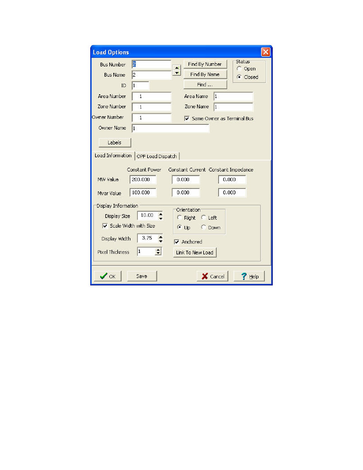
Left-click in the center of this bus. The Load Options Dialog box (pictured below) automatically opens. The
Constant Power MW and Mvar fields confirm that the load is 200 MW and 100 Mvar. In addition to constant
power loads, Simulator also allows the modeling of voltage dependent loads.
909
·
Select Up in the Orientation field under the Load Information tab to make the load point up. Verify that the
anchored box is checked to force the load to move with the selected bus.
·
Click OK to accept the default values for all remaining fields, close the Load Options dialog, and insert the
load. A circuit breaker symbol is automatically included with each load.
To move objects on the oneline:
·
Left-click on the desired object. Drag and drop the object to the new location by holding the left mouse
button down while moving the mouse. Note: you can also move all objects on the oneline simultaneously
by left-clicking on the diagram (not on a specific object) then dragging and dropping in the desired location.
·
To move bus 2, left click on bus 2 (not on the attached load). Drag the bus to a new location. Note that the
load moves with the bus because it is anchored. You can change the location of attached devices
connected to a bus, such as generators and loads, by the same procedure.
The oneline diagram should now resemble the image shown below.
910

Tutorials
911

Tutorial: Inserting a Transmission Line
Page 6 of 13
Transmission lines are used to connect buses together. To insert a transmission line:
· Select Insert > Transmission Line from the main menu, or click the AC Transmission Line
button on the
Insert Toolbar.
· Left-click at the point where you want the new line to originate. This point is usually located on one of the proposed
line’s terminal buses. For this example, originate the line at bus One.
· Transmission lines and transformers are drawn as a series of line segments. Without holding down the mouse
button, drag the mouse up. Notice that a line segment connected to the point of origin will follow your mouse
movements. To terminate a line segment, click the left mouse button. Each time you click the mouse to terminate
a line segment, a new vertex is defined for the line. To draw the next line segment, move the mouse to the desired
location of the next vertex. Note: the vertices may later be moved or deleted to reshape the line. To create curved
lines, hold the left mouse button down while dragging.
· To terminate the final line segment and conclude drawing the line, double click the left mouse button at the desired
termination point (bus Two for this example). The termination point is usually the transmission line’s other terminal
bus.
· The Transmission Line/Transformer Dialog automatically appears (shown below). The dialog should already contain
a 1 in the From Bus Number field and a 2 in the To Bus Number Field. If not, you probably did not have the cursor
directly on the bus when you were drawing the line. If this is the case, simply enter the correct bus numbers in the
corresponding fields.
912
Tutorials
· The Series Resistance, Series Reactance, and Shunt Charging fields are used to enter the per unit parameters
associated with the line. The Shunt Charging field contains the total per unit charging capacitance for the line.
Enter 0.02 in the Resistance field, 0.08 in the Reactance field and 0.1 in the Shunt Charging field.
· The Limit (MVA) fields contain the MVA ratings for the line; enter a value of 1000 in the Limit A (MVA) field. The
use of the other Limit (MVA) fields are described in ?????.
· Click OK to accept all remaining field default values, close the Transmission Line/Transformer Dialog, and insert the
new line.
By default, the transmission line is anchored to both terminal buses. If you try to move bus 2, the transmission line
should move with it.
913

Tutorial: Inserting a Line Flow Pie Chart on a Transmission Line Page 7 of 13
When the line is drawn it automatically it has a line flow pie chart included. You can include additional line flow pie
charts by clicking on the Line Flow Pie Chart
button and then clicking near a line. The Line/Transformer Flow
Pie Chart dialog box appears (shown below). Make sure that the From Bus and To Bus have the correct numbers,
that the MVA rating is correct, and that Anchored is checked. You may change the size of the pie chart by typing in a
value or using the arrows.
Color and behavior of pie charts are set in the Oneline Display Options display; right-click anywhere in the background
of the oneline, select Oneline Display Options from the pop-up menu, then select the Pie Charts tab (pictured below).
914

Tutorials
915

Tutorial: Inserting Circuit Breakers Page 8 of 13
Circuit breakers are used to control the status of the line. (If the line already has circuit breakers at each end, then
Simulator has been instructed to insert circuit breakers automatically. You can configure this option from the Default
Drawing Options Dialog).
To insert a Circuit Breaker:
·
Click somewhere on the line near bus One then select Insert > Circuit Breaker from the main menu or select the
Circuit Breaker
button and then click on the line near bus One. You should immediately see the Circuit
Breaker Options dialog (shown below) with the From Bus and To Bus fields correctly set to ‘1’ and ‘2’. If they are
‘0’, enter the correct value. Set the Size field to ‘1’ (you can either enter a 1, or use the spin arrows in change the
value).
·
Click OK to insert the circuit breaker.
In Simulator, the location of the circuit breaker does not matter, because changing the status of the circuit breaker
changes the status of the entire line. However, since most transmission lines have circuit breakers at each end, we
will also place a circuit breaker near bus 2. To accomplish this, repeat the above process near bus 2.
Save your case. Your oneline should now look similar to the image below.
916

Tutorials
Tutorial: Inserting a Transformer Page 9 of 13
To insert a transformer we first need to insert a bus at a different v oltage level. Insert a new bus in the bottom of the
oneline, named Three , and enter 69 KV for its nominal voltage in the Bus Options dialog box.
To insert a transformer between buses 2 and 3:
·
Either go to Insert > Transformer in the main menu, or select the Insert Transformer
button.
·
Click on bus 3, and then draw a line to bus 2 as you did for a transmission line. The Transmission
Line/Transformer Dialog automatically appears.
·
On the Parameters / Display tab, enter 0.02 for Series Resistance, 0.08 for Series Reactance, 0.1 for Shunt
Charging and 1000 for Limit A (MVA).
·
Select the Transformer Control tab. Note that the Off-nominal Turns Ratio displays 1.000. The true transformer
turns ratio does not need to be specified as it is automatically determined by the ratio of nominal voltages
between the From Bus and To Bus . The Off-nominal Turns Ratio is used to adjust the transformer tap setting on
per-unit values of bus voltages as referenced to their respective base values for per-unit calculation.
·
Click OK to accept the default values, close the dialog and insert the transformer.
·
Repeat this procedure to add a transformer between buses 1 and 3.
Add a 400 MW, 200 Mvar load to bus 3:
917
·
Right click on bus 3. Select Attached Devices tab. Click Add or Edit Bus Load.
·
Under Constant Power enter 400 in the MW Value field. Enter 200 in Mvar Value field. Click OK.
·
Note that Base MW and Base Mvar display the respective values. Click OK.
The load is now attached to the bus even though it is not displayed on the oneline. To display the load as an object on
the oneline, you can either use the Auto Insert feature or follow the procedure utilized earlier. To Auto Insert the
load:
·
Select Insert > Auto Insert > Loads… The Automatic Insertion of Loads dialog opens automatically.
·
Click OK to accept the default values and insert the load object on the oneline.
Note that Lines, Loads, Interfaces, Generators and Switched Shunts can all be inserted as objects on a oneline using
the Auto Insert tool if a record already exists for the device.
· Left-click and drag the load to the desired location on bus 3. Note: you can resize the bus object on the oneline
by left-clicking on the bus then dragging either end-point vertex to the desired bus size.
·
Right-click on the load and select Load Information Dialog. You can change the load orientation and verify all
load parameters in this dialog.
·
Click OK.
Next we are going to attach a 300 MW generator to the bus 3:
· Select Insert > Generator from the main menu, or click the Generator
button on the Insert Toolbar.
· Left-click on bus 3. The Generator Option Dialog opens.
· Select the MW and Voltage Control tab. Enter ‘300’ in the MW Output Field.
· Click OK on the Generator Option Dialog to accept the default values for all other fields. After the dialog box
closes, the new generator appears on the oneline attached to bus 3.
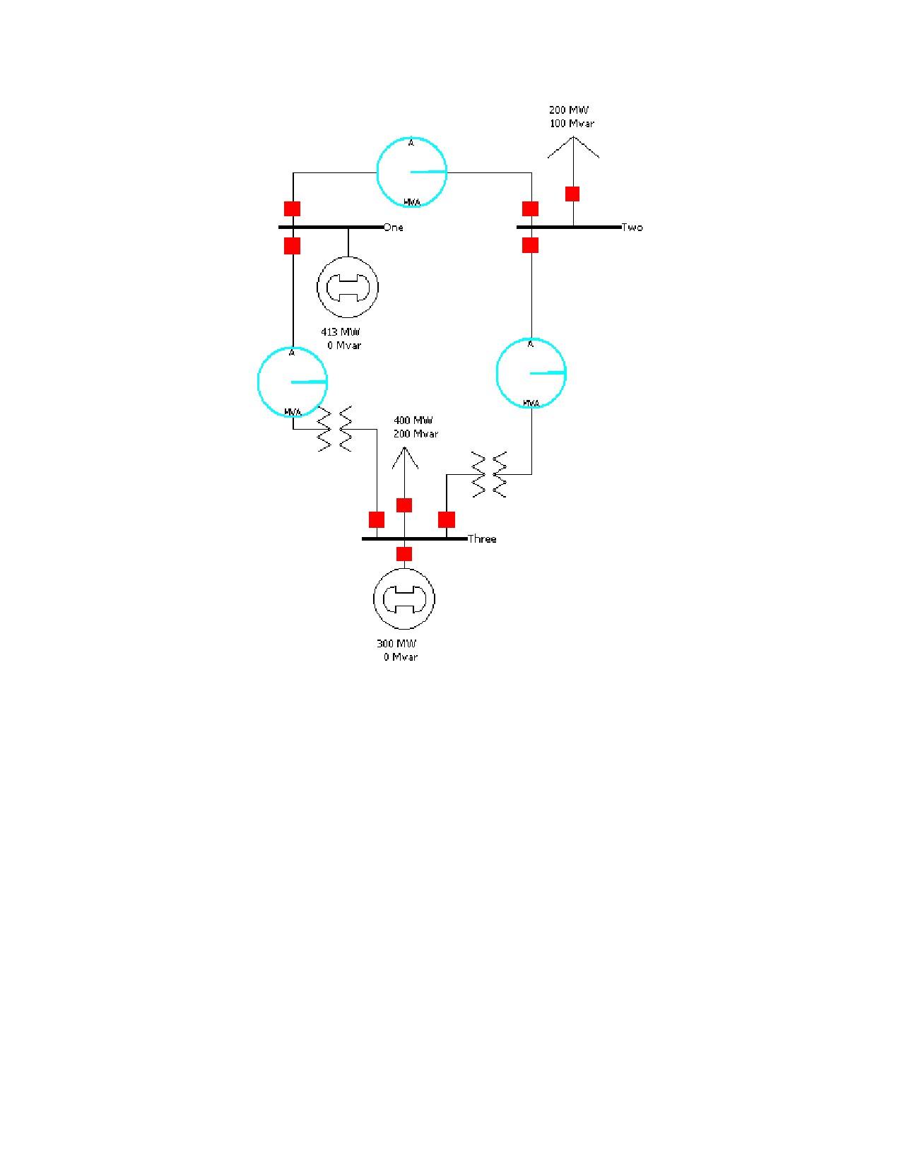
Your oneline should now resemble the image shown below.
918
Tutorials
919

Tutorial: Inserting a Switched Shunt Page 10 of 13
Switched shunts usually consist of either capacitors to supply reactive power (in MVAR) to the system, or reactors to
absorb reactive power. The switched shunts are represented by a number of blocks of admittance that can be
switched in a number of discrete steps. If at least one block is in service, the shunt is said to be online. The shunt’s
corresponding circuit breaker is used to determine and / or toggle the switched shunt’s status.
·
To insert a switched shunt at bus 3, either select Insert > Switched Shunt from the main menu, or select the
Switched Shunt
button.
·
Click near bus 3. The Switched Shunt Options dialog box appears (pictured below).
·
Verify that the bus number is 3; if it is not, change it.
·
Enter 10 for the Nominal Mvar.
·
Click OK to accept the default values of the remaining fields, close the dialog and insert the switched shunt.
Your oneline should now look like the image below.
920

Tutorials
921

Tutorial: Inserting Text, Bus and Line Fields Page 11 of 13
Informational fields can be entered directly on the oneline to allow for ease of monitoring when a simulation case is
run.
To insert a general text field:
·
Select Insert > Text from the main menu. Left-click on the oneline in the desired text location to bring up the
Text Object Dialog. (For this example, left-click in the top center of the oneline.)
·
Type the string "First Case" in the Enter the text field. Click OK.
·
To format the text, ensure the text is selected on the one-line then select Format > Font. This displays the Font
Tab of the Format Selection Dialog.
·
Set the font size to 26 and the font color to blue .
·
To change the text background color, select Format > Line /Fill, which summons the Line/Fill Options Tab . If the
format menu is already open, click on the Line/Fill Options Tab of the Format Selection Dialog. Check the Use
Background Fill box to give the text a white background, and then click OK.
·
Inserted text can be moved using the same method as any other object on the oneline
Fields can also display object-related quantities. By default, Simulator has inserted the bus names, generator and
load MW and MVAR, and switched shunt MVAR. For this example, we will add a Bus Voltage Magnitude field to each
bus and fields showing the power flow on the transmission line and the transformers. Note that object fields can be
formatted just like text fields by using the Format menu.
To add additional fields to the display of a particular bus:
· Right-click on the bus to bring up the bus’ local menu.
· Select Add New Fields Around Bus from the local menu. This opens the Insert Bus Fields Dialog (pictured below).
You may add up to 8 fields per bus. Select the position where you would like to add the new field (position 5 for this
example) then click OK.
922